EP0783274B1 - Coagulating forceps - Google Patents
Coagulating forceps Download PDFInfo
- Publication number
- EP0783274B1 EP0783274B1 EP94927194A EP94927194A EP0783274B1 EP 0783274 B1 EP0783274 B1 EP 0783274B1 EP 94927194 A EP94927194 A EP 94927194A EP 94927194 A EP94927194 A EP 94927194A EP 0783274 B1 EP0783274 B1 EP 0783274B1
- Authority
- EP
- European Patent Office
- Prior art keywords
- cutting
- electrode
- electrodes
- opposable
- tissue
- Prior art date
- Legal status (The legal status is an assumption and is not a legal conclusion. Google has not performed a legal analysis and makes no representation as to the accuracy of the status listed.)
- Expired - Lifetime
Links
Images


Definitions
- the present invention relates to an apparatus for an electrosurgical coagulation of regions of tissue or blood vessels over relatively large areas with temperature control.
- Surgical procedures and particularly electrosurgical procedures often require the complete cutoff of large regions of tissue, or the complete cutoff of the blood supply through a main artery before such surgery can be performed.
- a typical example is the requirement that the uterine artery be closed off before the uterus can be removed during a hysterectomy.
- the cutting off of the blood supply through the artery is accomplished by suture ligation, staples or clips or electrosurgical desiccation.
- suture ligation is a difficult and long procedure which increases the time required for anesthesia resulting in an opportunity for complicating factors to arise. Aside from an increase in the length of time, there is an obvious increase in the expense of the procedure.
- Uniform coagulation over large areas of tissue using standard electrosurgical techniques is extremely difficult to achieve. This difficulty is due in part to the fact that it is not known how to determine the proper rate at which to apply energy or how to determine when the desired amount of coagulation has been achieved. If the energy is applied too rapidly, the superficial layers of tissue may desiccate too quickly and insulate the deeper tissues from further application of electrosurgical energy. If insufficient energy has been applied, the desired depth of penetration of the electrosurgical energy may never be achieved.
- the only feedback currently available to an operator of some prior art electrosurgical devices is the visible inspection of the surface of the tissue which is being coagulated or monitoring of the level of RF current. Surface inspection is no indication of any effect achieved in deeper layers of tissue.
- US-A-5122137 and US-A-5190541 show an electrosurgical forceps with closable jaws both of which have rf electrodes in them.
- the rf electrodes are in intimate contact with temperature sensors which provide a feedback signal to the relevant electrode(s).
- US-A-5190541 additionally has cutting means associated with one of the jaws.
- one object of the present invention is to provide a novel apparatus for performing safe and rapid blood supply cutoff through an artery, a vessel, or other tissue in an efficient and sure manner withour the need for visual inspection.
- the present invention may also provide a single device which allows for both stoppage of blood supply and the cutting of the artery itself subsequent to stoppage of the blood supply.
- the operation of the device may be accomplished by a scissors-like movement of the forceps.
- the further object of the present invention provides a structure whereby split jaws of the coagulating forceps have an intermediate cutting blade combined with said forceps in order to sever the ligated vessel in the center of a coagulated area.
- the electrosurgical generation energy may be applied through a switching circuit, and there may be bipolar delivery of energy to the coagulating forceps.
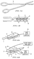
- Figure 1A and Figure 1B show that the forceps 10 having handles 11 and 12 forming a scissor-like arrangement by which the jaws 20 and 30 are brought into contact with the compressed vessel or tissue 17 as shown in Figure 1B.
- a plurality of electrodes 21 are shown on the upper jaw and a plurality of sensors 31 on the lower jaw. Although four electrodes 21 and four temperature sensors 31 are illustrated, any number and any arrangement or size of electrodes may be used depending upon the type of vessel or artery, vessel or other tissue which is to be cut off. That is, for different types of operations and for different types of arteries, vessels, or other tissues, different devices or forceps may be configured to conform with certain areas of the human body or certain access areas which are used in normal surgical procedures may be utilized.
- the forceps may be extended to form a needle-nose configuration or the size of the forceps may be reduced and accordingly the shape of the electrodes may be changed to take into account the size of the forceps.
- the configuration of the scissors-like arrangement is for purposes of illustration and the jaws may take the form of a clamping structure having either a straight head or an angled head as is normally used in any of a variety of clamping devices used for surgical procedures.
- the scissors-like structure may be replaced with any other mechanism that will cause the forceps jaws to be brought together when activated.
- various types of mechanisms typically used in devices for laparoscopic surgery would be available.
- a two-step procedure is involved in order to cut the vessel. That is, first the forceps 10 are clamped across the vessel as shown in Figure 1B and the tissue is heated for a predetermined period at a predetermined temperature in order to ensure the coagulation of the vessel. Then, the forceps is removed and a separate cutting device such as a knife or an electrosurgical cutting tool is used. This requirement for two devices in the two-step operation can be eliminated by the single device of Figure 2B.
- the Figures 2A and 2B illustrate a bifurcated top jaw with the electrodes 21 on the top jaw being divided between each of the two parts 38 and 39 of the top jaw.
- the bottom jaw 41 is a flat surface having a groove 42.
- the bottom surface contains the sensors 46 identical to the sensors 31 in Figure 1B.
- a cutting blade 49 schematically shown as attached to an electrosurgical unit power generator 50 of the type generally used for electrosurgical cutting procedure.
- the multi-segmented electrodes are powered and the tissue is heated by the power source controller 150 until the compressed vessel is coagulated and then the cutting blade 49, which slides between the upper jaws 38 and 39, cuts through the tissue into the lower groove 42.
- the cutting blade 49 which slides between the upper jaws 38 and 39, cuts through the tissue into the lower groove 42.
- Electrosurgical cutting requires less mechanical force and more completely assures the cutting of the tissue.
- a two-step operation is carried out using the same apparatus with the first step of the heating and coagulation of the tissue taking place separate from the actual cutting of the tissue.
- the cutting of the tissue is completely independent of the operation of the multi-segmented electrodes which have already accomplished the coagulation.
- the power is no longer supplied to the multi-segmented electrodes.
- the cutting blade either directly by mechanical force or through the action of an electrosurgical cutting accomplishes the actual cutting through of the tissue whose blood supply has been cut off by the prior coagulation. Essentially, this amounts to stopping blood flow on two sides of an area and then the subsequent cutting in the middle of the area with the stopping of blood flow and the cutting is accomplished by a single device.
- the Figure 2C illustrates a side blade cutting structure with a single pair of upper and lower jaws 38 and 41.
- the lower groove 42 still retains the cutting blade 49 after passing through the tissue in a manner similar to Figure 2B.
- the cutting action of the blade 49 can also be accomplished by an electro-surgical action in a manner similar to previously described operation of the cutting blade of Figure 2B.
- the exception to the operation of the instrument of Figure 2B is that the device of Figure 2C has a cutoff of blood supply or a coagulation on only one side of the area to be cut. Side cutting would be accomplished by the operation of the device of Figure 2C is useful in particularized areas of surgery which either do not require cutoff of blood supply on both sides of the tissue to be cut or require or prefer continued blood supply flow adjacent to one side of the cut area.
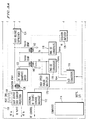
- the Figure 3 is a schematic representation of the power source controller 150 of Figures 2A and 2B and the switch matrix for the multi-segmented forceps discussed in conjunction with either Figure 1 or Figure 2.
- the electrical leads connect to the electrode-thermistor pairs of the forceps by way of connectors 138.
- the thermistor leads of the thermistors 31 (46) are connected to the matrix switchbank 134 and the electrode leads of electrodes 21 are connected to the switchbank 136.
- Each thermistor 31 (46) is sampled by means of a temperature measurement circuit 128 and the isolation amplifier 126 before being converted to digital form in the converter 116 and fed to the computer 114.
- the temperature measurement circuitry compares the measured temperature with a thermistor reference voltage 132.
- the electrode switch 136 is controlled in response to the output of the computer 114 by means of the opto-isolators 132.
- Input power from the RF input passes through the overvoltage and overcurrent protector 110 and is filtered by the bandpass filter 122 before being subjected to overvoltage suppression by the suppression unit 124.
- the voltage is isolated by means of transformers 138, 140 and 142 with the transformer voltages V i and V v from the transformers 142 and 144 being converted by the RMS-DC converters 118 into an RMS voltage to be fed to the converters 116. Prior to conversion, the signals V i and V v are also fed to the high-speed analog multiplier 120.
- RF control from computer 114 is provided through interface 112.
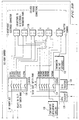
- the Figure 4 provides a schematic representation of the connection of power source controller 150 of Figure 3 to a multi-segmented electrode forceps having an illustrated four electrodes.
- the illustrated embodiment of Figure 4 shows a monopolar construction having a connection to a patient ground pad 120.
- the electrodes 121-124 may correspond to the electrodes 21 in Figure 1b and may be located on the upper jaw 20 in line or they may be located as shown in Figure 2 with two of the electrodes being on one of the upper split jaws 38 and the other two being on the upper split jaw 39.
- four electrodes are shown in the Figure 4, there is no limit based upon the principles of operation. Neither is there a limit on the arrangement of a particular number of electrodes on a particular portion of the jaw.
- the nature of the surgery to be performed and particularly the nature of the device for performing such surgery will provide the impetus for the size of the electrodes and the number of electrodes and the positioning of the electrodes on the forceps.
- Any large tissue area or vessel which needs to be coagulated can be covered by a number of electrodes by segmenting the large area into a number of smaller area electrodes of the type 121-124. With this type of structure of smaller area electrodes, individual control of the energy to each electrode through the switching circuit of Figure 4 is available in order to achieve controlled coagulation over a large area of tissue.
- the temperature sensors 31 or 46 are employed to sense the tissue temperature. Allowing the tissue temperature to reach a desired value and maintaining that temperature at that level for an appropriate period of time provides the physician with feedback concerning the coagulation process which would be impossible to achieve with a visible inspection of the surface tissue of the vessel being coagulated.
- This temperature feedback ideally provides for the control of the depth of the treatment and uses what is known as a "slow cook" of the tissue over a period of anywhere from several seconds to several minutes to achieve the desired therapeutic affect of cutting off the blood flow.
- thermotolerance of cells indicate that maintaining cells at 43°C for one hour produce a cell death. The time required is halved for each degree centigrade increase above 43°C. Cell death occurs because cellular enzymes necessary to support metabolism are destroyed.
- the multi-electrodes/temperature feedback concept for coagulating large areas or linear regions can be improved with respect to the delivery of energy to particular points by way of the switching arrangement of Figure 5 which provides for the ability to use either a monopolar operation or a bipolar operation.
- Figure 5 utilizes the same four electrodes 121-124 and a similar voltage source 210 with the same patient ground pad 120 as used in Figure 4.
- the essence of the Figure 5 monopolar/bipolar switching arrangement is that the physician or operator has the ability to provide either monopolar or bipolar operation.
- switch 220 is closed and the switches 216-219 remain open, the device functions essentially the same as the Figure 4 embodiment. That is, it provides monopolar operation.
- the electrodes 121-124 will provide a bipolar operation.
- switch 214 is closed as well as switch 218, then the current will pass from electrode 121 to electrode 123.
- switch 213 is closed as well as switch 219, there will be a bipolar operation with current flowing between electrode 122 and 124.
- Bipolar operation is not limited to these 121-123 and 122-124 pair couplings because if switch 214 and switch 217 are closed there will be bipolar operation between the electrodes 121 and 122 with current passing from 121 to 122.
- the embodiment of Figure 5 not only provides a choice between monopolar and bipolar operation but also provides a flexibility within the bipolar operation so that any two or any combination of pairs of electrodes 121-124 may be utilized together. Obviously, if switch 214 were thrown in conjunction with switch 216, nothing would occur because there would be a short.
- a coagulating forceps provides uniform coagulation over large areas of tissue by providing the proper application of energy to provide the desired depth of penetration without reliance on a visible inspection of the surface of the tissue or vessel being coagulated.
- the ability to segment the large area electrosurgical electrode into a number of smaller area electrodes and individually controlling the energy to each electrode through the multiplexing circuit of either Figure 4 or 5 provides a degree of flexibility beyond the state of the art as well as a degree of assurance heretofore unknown.
- use of many small electrodes is generally preferable to single large electrode.
- the advantage of many small electrodes is better controlled such as the ability to cause tissue to reach a therapeutic temperature with a small amount of power.
- the temperature sensors provide the feedback mechanism which allows the tissue temperature to reach a desired value and be maintained at that level for an appropriate period of time. This provides necessary information concerning the coagulation process which would otherwise be unavailable to the physician.
- the monitoring of the tissue impedance and the actual delivered power provide the ability to control the coagulation precisely.
- any number of sets of electrodes can be utilized depending upon the area and the location of the area to be coagulated and the head of the forceps can be angled or otherwise maneuvered using many of the same physiologic considerations provided for the selection of any surgical tool subject to electrical connection to the power generation source and the number of wires and space required for such connection.
Description
Claims (8)
- An implement (10) for selectively coagulating blood vessels (17) or tissues containing blood vessels, comprising:two opposable members (20,30) and a means for permitting movement of said two opposable members toward and away from each other;electroconductive electrode means (21) positioned on one of said two opposable members (20,30) for effecting electrical contact with said vessels to be coagulated;temperature sensing means (31,46) positioned on one of said two opposable members;radio frequency power means connected to said electrode means for selectively providing current to said electrode means from control means (150) as a function of the temperature sensed by the sensing means to thereby provide for coagulation of said vessels positioned between said two opposable members, characterized in that the electrode means (21) are on only one of the two opposable members (20) and the temperature sensing means (31,46) are only on the other (30) of the two opposable members.
- The implement according to claim 1, wherein said electroconductive electrode means (21) includes a plurality of separate electrodes (21) positioned on the one (20) of the two opposable members.
- The implement according to claim 2, further including a switching means (136) for providing individual control of power to each of said separate electrode means (21).
- The implement according to claim 2, wherein the one (20) of the two opposable members has a first portion (38) containing at least one electrode member (21) and a second portion spaced from said first portion and containing at least another electrode member (21), said implement further including a cutting means (49) positioned between said first and second portions (38,39) of said one opposable member.
- The implement according to claim 4, wherein the other (30) of said opposing members includes a groove (42) for receiving said cutting member (49) after cutting said vessels.
- The implement according to claim 4, wherein said cutting member (49) further includes an electrosurgical power source (50) to provide electrosurgical cutting.
- The implement according to claim 3, wherein said switching means includes a means for selecting at least one of monopolar and bipolar power to said electrode means.
- The implement according to claim 7, wherein said switching means includes a means for providing bipolar energy to said electrodes.
Applications Claiming Priority (1)
| Application Number | Priority Date | Filing Date | Title |
|---|---|---|---|
| PCT/US1994/009408 WO1996005776A1 (en) | 1993-08-16 | 1994-08-24 | Coagulating forceps |
Publications (3)
| Publication Number | Publication Date |
|---|---|
| EP0783274A1 EP0783274A1 (en) | 1997-07-16 |
| EP0783274A4 EP0783274A4 (en) | 1998-04-29 |
| EP0783274B1 true EP0783274B1 (en) | 2001-12-19 |
Family
ID=22242880
Family Applications (1)
| Application Number | Title | Priority Date | Filing Date |
|---|---|---|---|
| EP94927194A Expired - Lifetime EP0783274B1 (en) | 1994-08-24 | 1994-08-24 | Coagulating forceps |
Country Status (3)
| Country | Link |
|---|---|
| EP (1) | EP0783274B1 (en) |
| JP (1) | JPH10504485A (en) |
| DE (1) | DE69429543T2 (en) |
Cited By (1)
| Publication number | Priority date | Publication date | Assignee | Title |
|---|---|---|---|---|
| US9585714B2 (en) | 2006-07-13 | 2017-03-07 | Bovie Medical Corporation | Surgical sealing and cutting apparatus |
Families Citing this family (18)
| Publication number | Priority date | Publication date | Assignee | Title |
|---|---|---|---|---|
| US7458969B2 (en) | 2002-05-06 | 2008-12-02 | Olympus Corporation | Therapeutic device for tissue from living body |
| US7942874B2 (en) * | 2005-05-12 | 2011-05-17 | Aragon Surgical, Inc. | Apparatus for tissue cauterization |
| US20080243121A1 (en) * | 2007-04-02 | 2008-10-02 | Tomoyuki Takashino | Curative treatment system, curative treatment device, and treatment method for living tissue using energy |
| US20080243213A1 (en) * | 2007-04-02 | 2008-10-02 | Tomoyuki Takashino | Curative treatment system, curative treatment device, and treatment method for living tissue using energy |
| US20080249523A1 (en) * | 2007-04-03 | 2008-10-09 | Tyco Healthcare Group Lp | Controller for flexible tissue ablation procedures |
| WO2009130752A1 (en) | 2008-04-21 | 2009-10-29 | オリンパスメディカルシステムズ株式会社 | Therapy system, therapy instrument and method of treating living tissues with the use of energy |
| US8277446B2 (en) | 2009-04-24 | 2012-10-02 | Tyco Healthcare Group Lp | Electrosurgical tissue sealer and cutter |
| US20100280508A1 (en) * | 2009-05-01 | 2010-11-04 | Joseph Charles Eder | Method and Apparatus for RF Anastomosis |
| DE102010020664A1 (en) | 2010-05-05 | 2011-11-10 | Aesculap Ag | Surgical system for connecting body tissue parts |
| CN105246425B (en) | 2013-03-15 | 2018-03-09 | 捷锐士阿希迈公司(以奥林巴斯美国外科技术名义) | Bias surgical clamp |
| US20140276797A1 (en) | 2013-03-15 | 2014-09-18 | GYRUS ACMI, INC., d/b/a Olympus Surgical Technologies America | Combination electrosurgical device |
| EP2967741B1 (en) | 2013-03-15 | 2018-02-21 | Gyrus Acmi Inc. | Combination electrosurgical device |
| EP2974684B1 (en) | 2013-03-15 | 2017-08-30 | Gyrus ACMI, Inc. | Combination electrosurgical device |
| CN105163683B (en) * | 2013-03-15 | 2018-06-15 | 捷锐士阿希迈公司(以奥林巴斯美国外科技术名义) | Electrosurgical unit |
| CN103690237A (en) * | 2013-08-22 | 2014-04-02 | 安隽医疗科技(南京)有限公司 | Electrosurgery scalpel based on temperature and power control |
| US9913679B2 (en) | 2013-10-16 | 2018-03-13 | Covidien Lp | Electrosurgical systems and methods for monitoring power dosage |
| US9707028B2 (en) | 2014-08-20 | 2017-07-18 | Gyrus Acmi, Inc. | Multi-mode combination electrosurgical device |
| DE102019108140A1 (en) * | 2019-03-28 | 2020-10-01 | Karl Storz Se & Co. Kg | Bipolar electrosurgical tool |
Family Cites Families (1)
| Publication number | Priority date | Publication date | Assignee | Title |
|---|---|---|---|---|
| US5156151A (en) * | 1991-02-15 | 1992-10-20 | Cardiac Pathways Corporation | Endocardial mapping and ablation system and catheter probe |
-
1994
- 1994-08-24 DE DE69429543T patent/DE69429543T2/en not_active Expired - Lifetime
- 1994-08-24 JP JP8508018A patent/JPH10504485A/en active Pending
- 1994-08-24 EP EP94927194A patent/EP0783274B1/en not_active Expired - Lifetime
Cited By (1)
| Publication number | Priority date | Publication date | Assignee | Title |
|---|---|---|---|---|
| US9585714B2 (en) | 2006-07-13 | 2017-03-07 | Bovie Medical Corporation | Surgical sealing and cutting apparatus |
Also Published As
| Publication number | Publication date |
|---|---|
| EP0783274A1 (en) | 1997-07-16 |
| JPH10504485A (en) | 1998-05-06 |
| DE69429543T2 (en) | 2002-08-22 |
| EP0783274A4 (en) | 1998-04-29 |
| DE69429543D1 (en) | 2002-01-31 |
Similar Documents
| Publication | Publication Date | Title |
|---|---|---|
| US5443463A (en) | Coagulating forceps | |
| EP0783274B1 (en) | Coagulating forceps | |
| CA2608152C (en) | Apparatus for tissue cauterization | |
| US5827271A (en) | Energy delivery system for vessel sealing | |
| JP3585491B2 (en) | Impedance feedback electrosurgical system | |
| EP2155090B1 (en) | Surgical tool | |
| US5707369A (en) | Temperature feedback monitor for hemostatic surgical instrument | |
| AU2008201500B2 (en) | Controller for flexible tissue ablation procedures | |
| JP2005021703A (en) | Electrosurgical hemostatic device | |
| WO2003057058A1 (en) | Combined dissecting, cauterizing, and stapling device | |
| JP2000005188A (en) | Operation scissors having device for hemostasis by thermo-coagulation | |
| Brill | E lectricity is produced when valence electrons are freed from atoms of conductive materials. When these electrons are set in motion in the same direction an electric current (I) is produced that is measured in amperes. Opposite charges on the ends of the conductor cause the elec-trons to flow in one direction toward the positive terminal. The differ-ence in potential between the positive and negative poles provides the electromotive force (voltage) to drive the current through the conductor (Figure 1). | |
| Pasic et al. | Energy Systems in Laparoscopy |
Legal Events
| Date | Code | Title | Description |
|---|---|---|---|
| PUAI | Public reference made under article 153(3) epc to a published international application that has entered the european phase |
Free format text: ORIGINAL CODE: 0009012 |
|
| 17P | Request for examination filed |
Effective date: 19970313 |
|
| AK | Designated contracting states |
Kind code of ref document: A1 Designated state(s): DE FR GB IT |
|
| A4 | Supplementary search report drawn up and despatched |
Effective date: 19980311 |
|
| AK | Designated contracting states |
Kind code of ref document: A4 Designated state(s): DE FR GB IT |
|
| 17Q | First examination report despatched |
Effective date: 19991022 |
|
| GRAG | Despatch of communication of intention to grant |
Free format text: ORIGINAL CODE: EPIDOS AGRA |
|
| GRAG | Despatch of communication of intention to grant |
Free format text: ORIGINAL CODE: EPIDOS AGRA |
|
| GRAG | Despatch of communication of intention to grant |
Free format text: ORIGINAL CODE: EPIDOS AGRA |
|
| GRAH | Despatch of communication of intention to grant a patent |
Free format text: ORIGINAL CODE: EPIDOS IGRA |
|
| GRAH | Despatch of communication of intention to grant a patent |
Free format text: ORIGINAL CODE: EPIDOS IGRA |
|
| GRAA | (expected) grant |
Free format text: ORIGINAL CODE: 0009210 |
|
| AK | Designated contracting states |
Kind code of ref document: B1 Designated state(s): DE FR GB IT |
|
| RIC1 | Information provided on ipc code assigned before grant |
Free format text: 7A 61B 18/12 A |
|
| REG | Reference to a national code |
Ref country code: GB Ref legal event code: IF02 |
|
| REF | Corresponds to: |
Ref document number: 69429543 Country of ref document: DE Date of ref document: 20020131 |
|
| RAP2 | Party data changed (patent owner data changed or rights of a patent transferred) |
Owner name: SHERWOOD SERVICES AG |
|
| ET | Fr: translation filed | ||
| PLBE | No opposition filed within time limit |
Free format text: ORIGINAL CODE: 0009261 |
|
| STAA | Information on the status of an ep patent application or granted ep patent |
Free format text: STATUS: NO OPPOSITION FILED WITHIN TIME LIMIT |
|
| 26N | No opposition filed | ||
| REG | Reference to a national code |
Ref country code: FR Ref legal event code: CD Ref country code: FR Ref legal event code: CA |
|
| PGFP | Annual fee paid to national office [announced via postgrant information from national office to epo] |
Ref country code: GB Payment date: 20110825 Year of fee payment: 18 Ref country code: DE Payment date: 20110830 Year of fee payment: 18 Ref country code: FR Payment date: 20110830 Year of fee payment: 18 |
|
| PGFP | Annual fee paid to national office [announced via postgrant information from national office to epo] |
Ref country code: IT Payment date: 20110824 Year of fee payment: 18 |
|
| GBPC | Gb: european patent ceased through non-payment of renewal fee |
Effective date: 20120824 |
|
| REG | Reference to a national code |
Ref country code: FR Ref legal event code: ST Effective date: 20130430 |
|
| PG25 | Lapsed in a contracting state [announced via postgrant information from national office to epo] |
Ref country code: IT Free format text: LAPSE BECAUSE OF NON-PAYMENT OF DUE FEES Effective date: 20120824 |
|
| PG25 | Lapsed in a contracting state [announced via postgrant information from national office to epo] |
Ref country code: GB Free format text: LAPSE BECAUSE OF NON-PAYMENT OF DUE FEES Effective date: 20120824 Ref country code: DE Free format text: LAPSE BECAUSE OF NON-PAYMENT OF DUE FEES Effective date: 20130301 |
|
| PG25 | Lapsed in a contracting state [announced via postgrant information from national office to epo] |
Ref country code: FR Free format text: LAPSE BECAUSE OF NON-PAYMENT OF DUE FEES Effective date: 20120831 |
|
| REG | Reference to a national code |
Ref country code: DE Ref legal event code: R119 Ref document number: 69429543 Country of ref document: DE Effective date: 20130301 |