EP0782759B1 - Betätigungsvorrichtung für leistungsschalter - Google Patents
Betätigungsvorrichtung für leistungsschalter Download PDFInfo
- Publication number
- EP0782759B1 EP0782759B1 EP95933006A EP95933006A EP0782759B1 EP 0782759 B1 EP0782759 B1 EP 0782759B1 EP 95933006 A EP95933006 A EP 95933006A EP 95933006 A EP95933006 A EP 95933006A EP 0782759 B1 EP0782759 B1 EP 0782759B1
- Authority
- EP
- European Patent Office
- Prior art keywords
- operating device
- operating
- coil
- opening
- closing
- Prior art date
- Legal status (The legal status is an assumption and is not a legal conclusion. Google has not performed a legal analysis and makes no representation as to the accuracy of the status listed.)
- Expired - Lifetime
Links
Images


Classifications
-
- H—ELECTRICITY
- H01—ELECTRIC ELEMENTS
- H01H—ELECTRIC SWITCHES; RELAYS; SELECTORS; EMERGENCY PROTECTIVE DEVICES
- H01H3/00—Mechanisms for operating contacts
- H01H3/22—Power arrangements internal to the switch for operating the driving mechanism
- H01H3/28—Power arrangements internal to the switch for operating the driving mechanism using electromagnet
-
- H—ELECTRICITY
- H01—ELECTRIC ELEMENTS
- H01H—ELECTRIC SWITCHES; RELAYS; SELECTORS; EMERGENCY PROTECTIVE DEVICES
- H01H33/00—High-tension or heavy-current switches with arc-extinguishing or arc-preventing means
- H01H33/02—Details
- H01H33/28—Power arrangements internal to the switch for operating the driving mechanism
- H01H33/38—Power arrangements internal to the switch for operating the driving mechanism using electromagnet
-
- H—ELECTRICITY
- H01—ELECTRIC ELEMENTS
- H01H—ELECTRIC SWITCHES; RELAYS; SELECTORS; EMERGENCY PROTECTIVE DEVICES
- H01H33/00—High-tension or heavy-current switches with arc-extinguishing or arc-preventing means
- H01H33/02—Details
- H01H33/42—Driving mechanisms
Definitions
- the present invention relates to an electromagnetic operating device intended for medium-voltage or high-voltage circuit breakers and comprising an opening magnet and a closing magnet for operating the movable contact system of the circuit breaker.
- Electromagnetic operating devices are used above all in low-voltage circuit breakers.
- the driving force of the electromagnet it is common for the driving force of the electromagnet to be combined with the force of a return spring, such that the movable contact system may be displaced in opposite directions (make and break).
- Electromagnetic operating devices have also been used in older high-voltage circuit breakers of the type in which the contact system is enclosed in a grounded oil-filled tank.
- a known operating device of this kind two separate operating magnets for opening and closing, respectively, are used.
- the magnets are connected to the contact system via a mechanism, composed of a plurality of arms, links and rods, which by its relatively large weight, friction in all the rotary bearings, etc., is slow in operation and energy-demanding.
- the present invention aims to provide an electromagnetic operating device of the kind described in the preamble to claim 1, which is simpler, more reliable and less space-demanding than comparable prior art designs.
- the operating device shall be so designed that the energy losses caused by friction, etc., in the transmission between the magnets and the contact system are minimized, and that higher contact acceleration and contact speed may be achieved. This is achieved according to the invention with an operating device with the characteristic features mentioned in the characterizing part of claim 1.
- the two magnetic cores are integrated into one single magnet body, and the two armatures are adapted, by activation of the respective magnet coil, to be displaced translatorily along the longitudinal axis of the magnet body for opening and closing, respectively, of the circuit breaker.
- the two armatures are adapted, by activation of the respective magnet coil, to be displaced translatorily along the longitudinal axis of the magnet body for opening and closing, respectively, of the circuit breaker.
- holding coils are arranged adjacent to the operating coils to retain the respective armature in its end position, after a breaker operation, with the aid of relatively low magnetizing current.
- the operating mechanism is further simplified, since the need of mechanical latches, latching magnets and permanent magnets is eliminated.
- a magnetic operating device is most suitable for single-pole operation of SF 6 gas insulated circuit breakers.
- the operating device may be advantageously integrated into, under or adjacent to the respective breaker pole to form a hermetically sealed unit, filled with insulating gas, where all mechanical operations take place inside the unit.
- the operating device schematically shown in Figure 1 comprises a magnetic device consisting of, on the one hand, an opening magnet 11 comprising an opening coil 12, a magnet core 13 and an opening armature 14, and, on the other hand, a closing magnet 15 comprising a closing coil 16, a magnet core 17 and a closing armature 18.
- the two magnet cores 13, 17 with a magnet yoke connected thereto are integrated into a single magnet body 20, which together with the coils 12, 16 and the armatures 14, 18 form an operating magnet with a axi-symmetrical configuration.
- the magnet body 20 is formed with two hollow-cylindrical spaces 21, 22 separated by a transverse yoke 23 arranged in the mid-portion of the magnet body.
- the opening coil 12 is arranged in the upper space 21, whereas the closing coil 16 is arranged in the lower space 22.
- the opening armature 14, which extends into the space 21 at the upper end of the magnet body, is connected to the movable contact system of the circuit breaker via an insulating operating rod 19.
- the closing armature 18, which extends into the space 22 at the lower end of the magnet body 20, is provided with (or makes contact with) a push rod 24 (non-magnetic) which extends axially through the magnet body 20.
- the operating coils 12, 16 are connected to a common energy source 30 via separate thyristors 31 and 32, respectively, which are supplied with control current from a control circuit device 33.
- the energy source 30 may, for example, be a capacitor bank, an accumulator battery, or a rechargeable dry battery.
- Opening of the circuit breaker is initiated by firing the opening thyristor 31 by supplying control current from the control circuit device 33. This causes current to pass through the opening coil 12, the opening magnet 11 thus being magnetized and its armature 14 being drawn in the direction of the arrow A towards the interior of the core 13.
- the movable contact system of the circuit breaker which contact system is connected via the operating rod 19 direct to the armature 14, is thus moved to the open position and is retained there, for example by an open-position latch arranged adjacent to the armature 14.
- the closing thyristor 32 is fired, the closing magnet 15 thus being magnetized by the supply of current from the energy source 30.
- the closing armature 18 is thereby drawn in the direction of the arrow B towards the interior of the core 17 and, via the push rod 24 and the opening armature 14, brings about a displacement of the operating rod 19 in the direction of the arrow C.
- the movable contact system of the circuit breaker is thus displaced towards the closed position and is retained there, for example by a mechanical closed-position latch arranged adjacent to the armature 18.
- Figure 2 shows a further development of the magnet device shown in Figure 1, where, on the one hand, a first holding coil 25 is arranged adjacent to the opening coil 12 for retaining the movable contact system of the circuit breaker in the open position after an opening operation, and, on the other hand, a second holding coil 26 is arranged adjacent to the closing coil 16 for retaining the movable contact system of the circuit breaker in the closed position after a closing operation.
- the holding coils 25, 26 are designed for relatively low magnetizing current.
- the air gap X is almost reduced to zero, and the holding forces which are required may therefore be easily achieved by relatively small currents which may thus be delivered by the auxiliary power equipment in the distribution station in which the circuit breaker is placed.
- Figure 3 shows a time diagram for the coil currents in the magnetic device according to Figure 2 during closing and opening of a circuit breaker.
- the following designations for currents and time intervals are used in the diagram:
- the holding coils 25, 26 cooperate with the operating coils 12, 16 in such a way that the holding coils relieve the operating coils and complete the task of magnetizing the respective magnetic circuit and retaining the opening and the closing armature, respectively, in the end position of the respective armature movement.
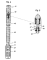
- Figures 4 and 5 show an integrated single-pole magnet-operated high-voltage circuit breaker consisting of a breaker pole of a type known per se, combined with an electromagnetic operating device according to the present invention.
- the shown breaker pole is an SF 6 circuit breaker of self-blasting type, described in the ABB pamphlet SESWG/B 2330E SF 6 Circuit-Breaker Type LTB", published 1993.
- the contact system of the breaker pole is arranged in an elongated casing 40 of insulating material provided with an upper and a lower connecting flange 41 and 42, respectively.
- the contact system whose central part is shown in Figure 5, comprises one fixed and one movable main contact 43 and 44, respectively, and one fixed and one movable arcing contact 45 and 46, respectively.
- a nozzle 47 of insulating material is arranged between the movable contacts 44 and 46 and is fixedly connected thereto.
- the movable contact system 44, 46 is connected, via a tubular contact rod 48, to the insulating operating rod 19, which extends through a hollow support insulator 49 and is connected at its lower end to the opening armature 14 of the operating device.
- the breaker pole and the operating device are coaxially arranged and have an elongated, substantially axi-symmetrical configuration.
- the breaker pole and the operating device together form one single, hermetically sealed unit which is filled with SF6 gas. All mechanical operations occur inside the closed unit.
- the operating device is provided with gas-tight bushings 27.
- the operating device may be built into the lower part of the support insulator by mutual adaptation of the transverse dimensions of the support insulator and the operating device. In this way, the operating device need not be provided with a separate casing, and the dimensions of the integrated breaker pole may be further reduced.
- An integrated breaker pole of the embodiment described entails great advantages, since it may be made completely ready for operation with the prescribed gas filling at the factory. This reduces the assembly work at the customer's site, which is largely limited to connecting two wires between the breaker pole and the energy supply equipment. (The return connection from the magnet coils 12, 16 can be grounded to the enclosures of the equipment.)
- connection rod for interconnecting the armatures can be used instead of the push rod 24 .
- gate turn-off thyristors instead of the ordinary thyristors 31, 32 shown in Figure 1.
Landscapes
- Physics & Mathematics (AREA)
- Electromagnetism (AREA)
- Driving Mechanisms And Operating Circuits Of Arc-Extinguishing High-Tension Switches (AREA)
- Cookers (AREA)
- Electrophonic Musical Instruments (AREA)
Claims (11)
- Elektromagnetische Betätigungsvorrichtung für Leistungsschalter mit einem Öffnungsmagneten (11) und einem Schliessmagneten (15), die jeweils eine Betätigungsspule (12, 16), einen Magnetkern (13, 17) und einen Anker (14, 18) umfassen zum Betätigen der beweglichen Stromzuführung des Schalters, dadurch gekennzeichnet, daß die beiden Magnetkerne (13, 17) konzentrisch in einen einzigen Magnetteil (2()) integriert sind, daß die Spule (12) und der Anker (14) des Öffnungsmagneten (12) am einen Ende des Magnetteiles angeordnet sind, wogegen die Spule (16) und der Anker (18) des Schließmagncten am anderen Ende des Magnetteiles (2()) angeordnet sind und daß die beiden Anker (14, 18) durch Erregen der entsprechenden Spulen (12, 16) entlang der Längsachse des Magnetteiles (20) seitlich versetzbar sind um den Leistungsschalter zu öffnen und zu schließen, wobei der Öffnungsanker (14) an die bewegliche Stromzuführung des Lcistungsschalters über eine erste Betätigungsstange (19) angeschlossen ist, wogegen der Schliessanker (18) vorgesehen ist, eine nichtmagnetische zweite, in Achsialrichtung des Magnetteiles verlaufende Betätigungsstange (24) zu verschieben um die bewegliche Stromzuführung über den Öffnungsanker zu betätigen.
- Betätigungsvorrichtung gemäß Patentanspruch 1, dadurch gekennzeichnet, daß die zweite Betätigungsstange (24) eine Schiebestange ist.
- Betätigungsvorrichtung gemäß Patentanspruch 1, dadurch gekennzeichnet, daß die zweite Betätigungsstange (24) eine Verbindungsstange für die Vcrbindung der Anker (14, 18) ist.
- Betätigungsvorrichtung gemäß irgendeinem der obigen Patentansprüche, dadurch gekennzeichnet, daß der Magnetteil (20) mit den zugehörigen Spulen (12, 16) und Ankern (14, 18) achsial symmetrisch ist.
- Betätigungsvorrichtung gemäß irgendeinem der obigen Patentansprüche, dadurch gekennzeichnet, daß der Magnetteil (20) zwei mit Hilfe eines Querjoches (23) getrennte Räume (21, 22) aufweist, wobei die Öffnungsspulc (12) im einen Raum (21) und die Schließspule (16) im anderen Raum (22) angeordnet ist.
- Betätigungsvorrichtung gemäß irgendeinem der obigen Patentansprüche, dadurch gekennzeichnet, daß die zweite Betätigungsstange (24) durch ein achsiales Zentrierloch im Magnetteil (20) verläuft.
- Betätigungsvorrichtung gemäß irgendeinem der obigen Patentansprüche, dadurch gekennzeichnet, daß eine erste Haltespule (25) neben der Öffnungsspule (12) angeordnet ist, um nach dem Öffnungsvorgang die bewegliche Stromzuführung des Leistungsschalter in offener Lage zu halten.
- Betätigungsvorrichtung gemäß irgendeinem der obigen Patentansprüche, dadurch gekennzeichnet, daß eine zweite Haltespule (26) neben der Schließspule (16) angeordnet ist um nach dem Schließvorgang die bewegliche Stromzuführung des Leistungsschalter in geschlossener Lage zu halten.
- Betätigungsvorrichtung gemäß irgendeinem der obigen Patentansprüche, dadurch gekennzeichnet, daß die Betätigungsspulen (12, 16) an eine gemeinsame Stromquelle (30 über getrennte Halbleiterschalter (31, 32) angeschlossen sind.
- Betätigungsvorrichtung gemäß Patentanspruch 8, dadurch gekennzeichnet, daß die Stromquelle aus einem Kondensatorsblock, einer Akkumulatorbatterie oder einer für automatische Aufladung versehenen Trockenbatterie besteht.
- Verwendung einer Betätigungsvorrichtung gemäß irgendeinem der obigen Patentansprüche in einem mit Druckgas isolierten Leistungsschalter für Mittcl- oder Hochspannung, wobei der Lcistungsschalter und die Betätigungsvorrichtung in einer hermetisch geschlossenen, mit Druckgas gefüllten Einheit integriert sind.
Applications Claiming Priority (3)
| Application Number | Priority Date | Filing Date | Title |
|---|---|---|---|
| SE9403138 | 1994-09-20 | ||
| SE9403138A SE9403138L (sv) | 1994-09-20 | 1994-09-20 | Manöverdon för brytare |
| PCT/SE1995/001066 WO1996009636A1 (en) | 1994-09-20 | 1995-09-19 | Operating device for circuit breakers |
Publications (2)
| Publication Number | Publication Date |
|---|---|
| EP0782759A1 EP0782759A1 (de) | 1997-07-09 |
| EP0782759B1 true EP0782759B1 (de) | 1999-05-26 |
Family
ID=20395292
Family Applications (1)
| Application Number | Title | Priority Date | Filing Date |
|---|---|---|---|
| EP95933006A Expired - Lifetime EP0782759B1 (de) | 1994-09-20 | 1995-09-19 | Betätigungsvorrichtung für leistungsschalter |
Country Status (6)
| Country | Link |
|---|---|
| EP (1) | EP0782759B1 (de) |
| JP (1) | JPH10505940A (de) |
| AT (1) | ATE180596T1 (de) |
| DE (1) | DE69509910D1 (de) |
| SE (1) | SE9403138L (de) |
| WO (1) | WO1996009636A1 (de) |
Cited By (2)
| Publication number | Priority date | Publication date | Assignee | Title |
|---|---|---|---|---|
| CN105609342A (zh) * | 2016-03-11 | 2016-05-25 | 天津市百利电气有限公司 | 一种低压断路器机械联锁装置 |
| CN106057513A (zh) * | 2016-07-21 | 2016-10-26 | 国网山西省电力公司电力科学研究院 | 可快速解锁的双稳态永磁操作机构主驱动电路 |
Families Citing this family (6)
| Publication number | Priority date | Publication date | Assignee | Title |
|---|---|---|---|---|
| DE19649979C1 (de) * | 1996-11-22 | 1998-01-15 | Siemens Ag | Elektrodynamischer Antrieb, insbesondere für Hochspannungsschaltgeräte |
| SE9604610D0 (sv) | 1996-12-16 | 1996-12-16 | Noviscens Ab | Medical composition |
| SE9702247D0 (sv) * | 1997-06-12 | 1997-06-12 | Asea Brown Boveri | Styranordning samt förfarande för att styra ett elektromagnetiskt manöverdon för brytare |
| CN1234135C (zh) | 2001-01-18 | 2005-12-28 | 株式会社日立制作所 | 电磁铁和使用该电磁铁的开关装置的操作机构 |
| JP5617759B2 (ja) * | 2011-05-12 | 2014-11-05 | 三菱電機株式会社 | 電磁操作式真空遮断器 |
| CN113284747B (zh) * | 2021-05-20 | 2023-03-24 | 浙江万松电气有限公司 | 用于专用型双电源自动转换开关电器的中性线重叠机构 |
Family Cites Families (4)
| Publication number | Priority date | Publication date | Assignee | Title |
|---|---|---|---|---|
| US1645628A (en) * | 1926-07-03 | 1927-10-18 | Warren S Smith | Magnetically-operated signal |
| US2838630A (en) * | 1956-07-16 | 1958-06-10 | Mc Graw Edison Co | Switch construction |
| US3900822A (en) * | 1974-03-12 | 1975-08-19 | Ledex Inc | Proportional solenoid |
| DE3934287A1 (de) * | 1989-10-13 | 1991-04-18 | Eckehart Schulze | Magnetventil |
-
1994
- 1994-09-20 SE SE9403138A patent/SE9403138L/ not_active Application Discontinuation
-
1995
- 1995-09-19 AT AT95933006T patent/ATE180596T1/de active
- 1995-09-19 EP EP95933006A patent/EP0782759B1/de not_active Expired - Lifetime
- 1995-09-19 DE DE69509910T patent/DE69509910D1/de not_active Expired - Lifetime
- 1995-09-19 WO PCT/SE1995/001066 patent/WO1996009636A1/en active IP Right Grant
- 1995-09-19 JP JP8510812A patent/JPH10505940A/ja active Pending
Cited By (3)
| Publication number | Priority date | Publication date | Assignee | Title |
|---|---|---|---|---|
| CN105609342A (zh) * | 2016-03-11 | 2016-05-25 | 天津市百利电气有限公司 | 一种低压断路器机械联锁装置 |
| CN105609342B (zh) * | 2016-03-11 | 2019-01-11 | 天津市百利电气有限公司 | 一种低压断路器机械联锁装置 |
| CN106057513A (zh) * | 2016-07-21 | 2016-10-26 | 国网山西省电力公司电力科学研究院 | 可快速解锁的双稳态永磁操作机构主驱动电路 |
Also Published As
| Publication number | Publication date |
|---|---|
| SE9403138D0 (sv) | 1994-09-20 |
| JPH10505940A (ja) | 1998-06-09 |
| WO1996009636A1 (en) | 1996-03-28 |
| ATE180596T1 (de) | 1999-06-15 |
| DE69509910D1 (de) | 1999-07-01 |
| SE9403138L (sv) | 1996-03-21 |
| EP0782759A1 (de) | 1997-07-09 |
Similar Documents
| Publication | Publication Date | Title |
|---|---|---|
| EP2312606B1 (de) | Bistabiler magnetischer Aktuator für einen Mittelspannungsschutzschalter | |
| RU2324995C1 (ru) | Электромагнитный привод и прерыватель цепи, содержащий этот привод | |
| EP0354803A1 (de) | Bistabiler magnetischer Betätiger und Schalter | |
| US9659727B2 (en) | Switch | |
| KR101668341B1 (ko) | 개폐 장치 | |
| KR100641025B1 (ko) | 전자기력을 이용한 조작기 및 이를 이용한 차단기 | |
| EP3748662A1 (de) | Kinetischer aktuator für vakuumunterbrecher | |
| WO2001050562A1 (en) | Isolator switch | |
| US7718913B2 (en) | Actuation by cylindrical CAM of a circuit-breaker for an alternator | |
| US9818562B2 (en) | Switch | |
| US11152178B2 (en) | Disconnect switches with combined actuators and related circuit breakers and methods | |
| US10957505B2 (en) | Disconnect switch assemblies with a shared actuator that concurrently applies motive forces in opposing directions and related circuit breakers and methods | |
| EP0782759B1 (de) | Betätigungsvorrichtung für leistungsschalter | |
| CN102280304A (zh) | 动触头组件及其应用动触头组件的电磁隔离驱动智能开关 | |
| US5750949A (en) | Metal-encapsulated, gas-insulated high-voltage circuit-breaker | |
| KR19990047296A (ko) | 마그네틱 액튜에이터를 이용한 지중선로용 다회로자동 차단기 | |
| JPS61256542A (ja) | 短絡回路電流に対する保護スイツチング装置 | |
| CN209844393U (zh) | 环保气体绝缘全封闭断路器柜 | |
| RU2224318C1 (ru) | Вакуумный выключатель | |
| KR20080063912A (ko) | 변전설비 차단기용 액츄에이터 | |
| JP2003331700A (ja) | 電力用開閉装置 | |
| CN201332047Y (zh) | 一种sf6高压断路器电磁力驱动机构 | |
| SU1069023A1 (ru) | Быстродействующий высоковольтный коммутационный аппарат | |
| GB1149585A (en) | Fluid-blast circuit interrupter with flow producing piston and cylinder assembly and electromagnetic driving means therefor | |
| CN101447364B (zh) | Sf6高压断路器电磁力驱动机构 |
Legal Events
| Date | Code | Title | Description |
|---|---|---|---|
| PUAI | Public reference made under article 153(3) epc to a published international application that has entered the european phase |
Free format text: ORIGINAL CODE: 0009012 |
|
| 17P | Request for examination filed |
Effective date: 19970218 |
|
| AK | Designated contracting states |
Kind code of ref document: A1 Designated state(s): AT BE DE FR GB IT NL SE |
|
| GRAG | Despatch of communication of intention to grant |
Free format text: ORIGINAL CODE: EPIDOS AGRA |
|
| 17Q | First examination report despatched |
Effective date: 19980928 |
|
| GRAG | Despatch of communication of intention to grant |
Free format text: ORIGINAL CODE: EPIDOS AGRA |
|
| GRAH | Despatch of communication of intention to grant a patent |
Free format text: ORIGINAL CODE: EPIDOS IGRA |
|
| GRAH | Despatch of communication of intention to grant a patent |
Free format text: ORIGINAL CODE: EPIDOS IGRA |
|
| GRAA | (expected) grant |
Free format text: ORIGINAL CODE: 0009210 |
|
| AK | Designated contracting states |
Kind code of ref document: B1 Designated state(s): AT BE DE FR GB IT NL SE |
|
| PG25 | Lapsed in a contracting state [announced via postgrant information from national office to epo] |
Ref country code: SE Free format text: THE PATENT HAS BEEN ANNULLED BY A DECISION OF A NATIONAL AUTHORITY Effective date: 19990526 Ref country code: NL Free format text: LAPSE BECAUSE OF FAILURE TO SUBMIT A TRANSLATION OF THE DESCRIPTION OR TO PAY THE FEE WITHIN THE PRESCRIBED TIME-LIMIT Effective date: 19990526 Ref country code: IT Free format text: LAPSE BECAUSE OF FAILURE TO SUBMIT A TRANSLATION OF THE DESCRIPTION OR TO PAY THE FEE WITHIN THE PRE;WARNING: LAPSES OF ITALIAN PATENTS WITH EFFECTIVE DATE BEFORE 2007 MAY HAVE OCCURRED AT ANY TIME BEFORE 2007. THE CORRECT EFFECTIVE DATE MAY BE DIFFERENT FROM THE ONE RECORDED.SCRIBED TIME-LIMIT Effective date: 19990526 Ref country code: FR Free format text: LAPSE BECAUSE OF FAILURE TO SUBMIT A TRANSLATION OF THE DESCRIPTION OR TO PAY THE FEE WITHIN THE PRESCRIBED TIME-LIMIT Effective date: 19990526 Ref country code: BE Free format text: LAPSE BECAUSE OF FAILURE TO SUBMIT A TRANSLATION OF THE DESCRIPTION OR TO PAY THE FEE WITHIN THE PRESCRIBED TIME-LIMIT Effective date: 19990526 Ref country code: AT Free format text: LAPSE BECAUSE OF FAILURE TO SUBMIT A TRANSLATION OF THE DESCRIPTION OR TO PAY THE FEE WITHIN THE PRESCRIBED TIME-LIMIT Effective date: 19990526 |
|
| REF | Corresponds to: |
Ref document number: 180596 Country of ref document: AT Date of ref document: 19990615 Kind code of ref document: T |
|
| REF | Corresponds to: |
Ref document number: 69509910 Country of ref document: DE Date of ref document: 19990701 |
|
| PG25 | Lapsed in a contracting state [announced via postgrant information from national office to epo] |
Ref country code: DE Free format text: LAPSE BECAUSE OF FAILURE TO SUBMIT A TRANSLATION OF THE DESCRIPTION OR TO PAY THE FEE WITHIN THE PRESCRIBED TIME-LIMIT Effective date: 19990827 |
|
| PG25 | Lapsed in a contracting state [announced via postgrant information from national office to epo] |
Ref country code: GB Free format text: LAPSE BECAUSE OF NON-PAYMENT OF DUE FEES Effective date: 19990919 |
|
| EN | Fr: translation not filed | ||
| PLBE | No opposition filed within time limit |
Free format text: ORIGINAL CODE: 0009261 |
|
| STAA | Information on the status of an ep patent application or granted ep patent |
Free format text: STATUS: NO OPPOSITION FILED WITHIN TIME LIMIT |
|
| GBPC | Gb: european patent ceased through non-payment of renewal fee |
Effective date: 19990919 |
|
| EUG | Se: european patent has lapsed |
Ref document number: 95933006.9 |
|
| 26N | No opposition filed |