EP0782511B1 - Variable speed warning device - Google Patents
Variable speed warning device Download PDFInfo
- Publication number
- EP0782511B1 EP0782511B1 EP95930265A EP95930265A EP0782511B1 EP 0782511 B1 EP0782511 B1 EP 0782511B1 EP 95930265 A EP95930265 A EP 95930265A EP 95930265 A EP95930265 A EP 95930265A EP 0782511 B1 EP0782511 B1 EP 0782511B1
- Authority
- EP
- European Patent Office
- Prior art keywords
- vehicle
- speed
- emergency
- voltage
- minimum
- Prior art date
- Legal status (The legal status is an assumption and is not a legal conclusion. Google has not performed a legal analysis and makes no representation as to the accuracy of the status listed.)
- Expired - Lifetime
Links
Images





Classifications
-
- B—PERFORMING OPERATIONS; TRANSPORTING
- B60—VEHICLES IN GENERAL
- B60Q—ARRANGEMENT OF SIGNALLING OR LIGHTING DEVICES, THE MOUNTING OR SUPPORTING THEREOF OR CIRCUITS THEREFOR, FOR VEHICLES IN GENERAL
- B60Q1/00—Arrangement of optical signalling or lighting devices, the mounting or supporting thereof or circuits therefor
- B60Q1/26—Arrangement of optical signalling or lighting devices, the mounting or supporting thereof or circuits therefor the devices being primarily intended to indicate the vehicle, or parts thereof, or to give signals, to other traffic
- B60Q1/2611—Indicating devices mounted on the roof of the vehicle
Definitions
- the invention relates generally to emergency signalling devices, and more particularly to an signalling method and apparatus for an emergency vehicle having a signalling frequency corresponding to the speed of the vehicle.
- Emergency vehicles such as police cars, ambulances and fire trucks are required to perform under a wide range of driving conditions and at a wide range of speeds. For example, during the time that a police car is in pursuit of a suspect car, the police car may be driven at a high rate of speed for a given time, at a reduced speed while crossing critical intersections, and stopped once the vehicle is halted.
- the primary responsibility of the emergency signalling system is to warn the public of the presence of the vehicle, since the emergency vehicle is often driven in a non-standard manner during such extraordinary times.
- conventional lights and sirens provide recognizable patterns and various colors or tones.
- the flashing or strobing lights of the vehicle are broadcasting information to potential observers such that once detected, the observer is warned of the abnormal driving conditions that may soon be encountered so that appropriate precautionary measures may be taken.
- light bars composed of anywhere from two to twelve light elements, wherein each element is ordinarily capable of flashing at a rate of between 60 and 240 flashes per minute (one to four hertz)
- SAE J-845, SAE J-595, SAE J-1318 for emergency warning lights.
- the lights may be filtered so that non-white colors allow the observer to differentiate between the white and red lights of ordinary vehicles and also to differentiate between the types of emergency vehicles.
- the combination of flashing or strobing lights, at a particular pattern and of a distinguishable color signifies to the public the presence of an active emergency vehicle.
- a warning issued by an emergency signalling device attempts to maximize the effectiveness of the warning by including enough information to overcome observational difficulties that are potentially present in the general public.
- emergency sirens often sweep through a range of frequencies at varying rates.
- the maximum and minimum frequencies are arranged so as to be within the most efficient detection portion of the human audio spectrum.
- the purpose of sweeping through a range of frequencies is to ensure that potential human observers will hear the siren over background noises and because many potential observers suffer from hearing loss at certain frequencies.
- the rate of sweeping between the frequencies is also chosen to impart information, usually indicative of urgency, to the public.
- a frequency pattern known as a "Wail” sweeps from approximately a 500 hertz tone to a 1500 hertz tone in ten to thirty sweeps per minute.
- a frequency pattern known as a "Yelp” sweeps between the same audible tones but at a much faster rate of approximately 150 to 250 sweeps per minute.
- the "Yelp" pattern is able to rapidly impart the signalling information, even to persons having limited ability to hear certain frequencies, so that a faster reaction than with the "Wail" tone is possible.
- light bars provide a variety of colors in a single light package. These varying colors aid the stimulation of unoccupied visual channels in human observers and overcome visual deficiencies such as color blindness present in some potential observers. Additionally, having a greater number of flashing light elements provides a greater number of flashes to the eye, which potentially results in faster reaction times.
- FR-A-2 230 187 discloses a lighting device for use with a motor vehicle, said lighting device having a light source and means for operating the light source as a flashing light source with a flash rate being strictly proportional to the speed of the vehicle.
- the tachometer drive shaft of the vehicle actuates a switch for switching the light source on and off with a switch rate proportional to the rate of revolutions of the tachometer drive shaft so that the flash rate of the light source is always proportional to the speed of the vehicle.
- FR-A-2 230 187 describes an example where the following flash rates are associated with certain speeds: 1 hertz with 40 km/h, 2 hertz with 80 km/h, 3 hertz with 120 km/h etc. Therefore, at low vehicle speeds a human observer may not even notice the flashing action of the light source, and at high vehicle speeds the flash rate may be so high that the flashing operation of the light source is no more perceived by a human observer.
- the invention therefore provides an emergency signalling device for broadcasting emergency signals from a vehicle.
- Mounting means connect the signalling device to the vehicle, and a detector converts the speed of the vehicle to a first electrical signal having information therein corresponding to the speed of the vehicle.
- Circuitry converts the first electrical signal to a second electrical signal having a repetition rate corresponding to the speed of the vehicle, and circuitry is also provided for maintaining the repetition rate between maximum and minimum rates.
- Means connect the second electrical signal to the signalling device for broadcasting emergency signals having a variable range of repetition rates corresponding to the speed of the vehicle between maximum and minimum signalling rates.
- the emergency signalling device is provided in an emergency lighting device mounted to the surface of a motor vehicle.
- the signalling device includes a base and related apparatus for mounting to the surface of the motor vehicle, a flashing light mounted to the base, and a light transmissive housing supported by the base for enclosing and protecting the light.
- a detector detects the speed of the vehicle, and circuitry responsive thereto controls a flash rate of the flashing light so that the rate varies with the speed of the vehicle between minimum and maximum flash rates.
- the method of operating emergency signalling devices mounted to a motor vehicle comprises the step of generating an emergency signal that is characterized by a repetition of at least one audio tone or the flashing of lights.
- the rate of repetition of the emergency signal is maintained at a minimum value for speeds of the motor vehicle below a predetermined lower limit and at a maximum value for speeds of the motor vehicle above a predetermined upper limit, and the repetition rate of the emergency signal is adjusted to create a proportional relationship between the repetition rate and the speed of the vehicle for speeds between the lower and upper limits.
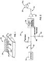
- an emergency signalling device generally designated 20 including a base 22 and incorporated mounting apparatus for mounting to a surface of a motor vehicle, ordinarily the motor vehicle's roof, and a plurality of light sources 24, 24a mounted to the base 22.
- the base 22 supports a light housing 26 which is dimensioned to enclose and protect the light sources 24, 24a, the light housing 26 being transmissive to at least one frequency of light generated by the light sources 24, 24a.
- the exemplified signalling device is illustrated as a plurality of light sources 24, 24a within a light bar, it can readily be appreciated that virtually any base, housing and light source design will suffice for the purposes of the present invention.
- the base 22 may be arranged to mount one or more speakers 24c to the vehicle.
- a signalling device 20 (FIG. 4) is controllably driven to impart speed-dependent information to observers during an emergency situation.
- the signalling device 20 includes at least one light source such as the single light source 24a, which is capable of being intermittently illuminated by a drive means 28, for example, a suitably connected transistor, relay, silicon controlled rectifier, mechanical switch, or the like.
- a motor 30 is utilized to rotate a constant directional light source 24b such that it appears to be intermittently flashing.
- a speaker 24c (FIG. 9) is controllably driven with one or more audible frequencies.
- a suitable driving circuit is employed to trigger the driving circuitry 28 to controllably flash or rotate the light source, or to drive a speaker.
- FIGs. 2-4 and 9-10 show examples of possible electrical driving circuits capable of controlling the operation of the signalling device 20 according to the invention.
- detector 32 is assumed to provide a voltage output having a magnitude that substantially corresponds to the speed of the vehicle, at least within the speed ranges described herein.
- the speed-dependent voltage might be obtained by an appropriate electrical connection to a standard voltage-driven speedometer.
- the voltage obtained from the detector 32 may first be conditioned, for example, amplified, attenuated, or filtered to remove noise or other voltage spikes, before being utilized.
- the detector 32 might instead be a radar or laser speed gun that is arranged to obtain the speed of the vehicle relative to the stationary ground, a magnet connected to the wheel that closes and opens a switch to trigger a counter in accordance with the revolution of a wheel, an air speed detector, and so on.
- the voltage obtained from the detector 32 will be assumed to vary between 0 and 12 volts in direct linear proportion to the speed of the vehicle between 0 and 120 miles per hour. Also for the sake of simplicity, the forward voltage drops of the diodes present in the circuits hereinafter described are disregarded. Finally, the input impedances of the various driving circuits are assumed to be high enough so that the influence of the driving circuits' impedance on the input voltage is negligible.
- FIG. 2 shows one such suitable driving circuit, generally designated 34, wherein the voltage from the detector 32 is utilized in conjunction with a voltage-to-frequency converter 36 to intermittently flash the light source 24a.
- the speed of the vehicle reflected in the output voltage from the detector 32, determines the frequency, i.e, flash rate, of the light source 24a.
- a driver 28 is employed, for example a relay, transistor, and so on as previously described.
- the signalling device 20 may be arranged to switch between differently colored lights.
- the signalling device 20 will not be effective if the light flashes (or if tones are sounded) too slowly or becomes stopped as the vehicle is slowed or stopped. Similarly, it will also be appreciated that the signalling device 20 would be rendered ineffective it were allowed to transmit information at a rate that was no longer detectable by humans, or even if detectable, was too fast to be effective. For example, a four hertz rate might be deemed to be the maximum rate that is acceptable for still broadcasting an effective warning to a human eye.
- diode 40 when the voltage from the detector 32 drops below a predetermined minimum amount, for example one volt corresponding to ten miles per hour, diode 40 begins to conduct ensuring that at least one volt (V minimum) is always present at the input of voltage-to-frequency converter 36.
- V minimum a volt
- a diode 42 blocks current from flowing in the reverse direction.
- a zener diode 46 connected to the detector 32 output breaks down and begins to conduct ensuring that no more than six volts is ever present at the input of voltage-to-frequency converter 36.
- a pair of resistors 48, 50 protect the blocking diode 42 and zener diode 46, respectively, from the voltage drops that result when the zener diode 46 begins to conduct.
- the values of resistors 48 and 50 are preferably chosen so as to neither draw excessive current nor significantly influence the circuit impedance over the range of all possible input voltages.
- a predetermined maximum for example sixty miles per hour
- a certain predetermined maximum frequency is output by the voltage-to-frequency converter 36. Accordingly, even at high speeds the light flashes at a frequency that is arranged to be not too fast to be perceived by an ordinary observer.
- the voltage output by the detector 32 remains proportional to the speed, for example four volts for forty miles per hour, three volts for thirty miles per hour, and so on.
- diode 40 nor zener diode 46 conducts current at these voltages, and thus the output frequency of the voltage-to-frequency converter 36 is proportional to the vehicle speed.
- An appropriately arranged voltage-to-frequency converter (voltage controlled oscillator) 36 provides the desired frequencies for the desired input voltages. Moreover, typical voltage-to-frequency converters also provide for selection of an appropriate duty cycle. Thus, for example, the minimum frequency might be selected as 0.4 Hertz (resulting in 24 flashes per minute) and the maximum at four hertz (resulting in 240 flashes per minute, according to the appropriate SAE standard) with a fifty percent duty cycle.
- a light source that radiates light primarily in one direction (or two opposite directions) may be rotated at an appropriate frequency, thus appearing to be flashing when perceived by a relatively stationary observer.
- the pulses may be utilized to drive a stepper motor, via an appropriate driver 28, or alternatively a circuit such as the circuit in FIG. 3 may be utilized. Note that identically referenced numerals in FIG. 3 correspond to identically referenced components of FIG. 2 and function similarly.
- the voltage is used to drive a direct current (DC) motor 30, the motor 30 having a variable speed of rotation dependent on the input voltage. Accordingly, the motor 30, mechanically connected to the light source 24b, rotates the light source 24b in proportion to the speed of the vehicle. As described previously, the voltage is clamped by the diode 40 and the zener diode 46 between maximum and minimum values to ensure that the speed of rotation resulting in the signalling by the light is neither too slow nor too fast to be perceived.
- a switch 56 may be placed such as in FIG. 3 to selectively control both the application of current to the motor 30 and the illumination of the light source 24b.
- an appropriate motor drive 54 such as a transistor-based current amplifier is used to supply the necessary current.
- the voltage at the input of the motor drive 54 may be amplified or attenuated as necessary to adjust for the needs of the motor 30, or the motor 30 may be geared to adjust for the voltage.
- the motor might rotate at 1000 revolutions per minute at twelve volts, 500 revolutions per minute at six volts.
- the motor can be geared down at a two-to-one ratio (i.e., 250 revolutions-per-minute at six volts) and the maximum voltage (six volts) attenuated to 5.76 volts.
- the input voltage can be halved to halve the frequency of rotation.
- a microprocessor 60 is employed to process the speed of the vehicle to output or otherwise control a signal pulse having a frequency ultimately dependent on the speed of the vehicle.
- the signal pulse is then used to operate the signalling device 20 in accordance therewith.
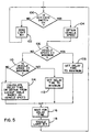
- the operation of the microprocessor 60 will be described in conjunction with the flowchart of FIG. 5.
- the steps described herein may be implemented as a single routine in a more complex program, thus allowing the light sources 24, 24a to be flashed in any number of additional patterns.
- the microprocessor 60 checks the status of an input line 61 to determine if an emergency signalling operation is requested at emergency switch 62. If the emergency switch 62 is not on, the microprocessor clears the appropriate output line 64 to zero at step 102 by appropriately masking an output port thereof (such as by AND-ing the appropriate bit of an eight-bit output port with zero), and loops back to continually await activation.
- the microprocessor obtains a voltage reading from the detector 32 as sampled by an analog-to-digital voltage converter (A-D converter) 66 (FIG. 4).
- A-D converter analog-to-digital voltage converter
- a suitable latch might be employed, or alternatively, the microprocessor 60 could trigger the voltage sample by outputting an appropriate timing pulse, and subsequently delay long enough to ensure that the conversion was complete before the A-D converter 66 output data was read into the microprocessor 60.
- the microprocessor 60 compares the voltage data with a predetermined minimum value, either hard-coded into the executing program or stored independent of the program code in a non-volatile memory 68 operatively connected thereto. If the value is at or below the minimum, the microprocessor 60 sets a delay time variable equal to a maximum value (step 108).
- a delay variable is set that takes 1.25 seconds to decrement to zero within a loop. For example, if the execution time of a delay loop that decrements a register to zero takes 100 microseconds, then decrementing a register initially loaded with a value of 12,500 takes 1.25 seconds to reach zero and thereby exit the loop.
- the speed is compared to a maximum value at step 110. For example, if the voltage is at 7.7 volts, corresponding to 77 miles per hour, a 4.0 hertz maximum flashing frequency is desired. Accordingly, a total delay time of 0.25 seconds is required (0.125 "On” and 0.125 “Off” assuming a fifty percent duty cycle). Thus, the delay variable would be set (at step 112) that takes 0.125 seconds to decrement to zero within a loop. As in the above example, if the execution time of a delay loop that decrements a register to zero takes 100 microseconds, then decrementing a register initially loaded with 1,250 takes 0.125 seconds to reach zero and thereby exit the loop.
- the delay variable may either be obtained from a look-up table or calculated as shown in step 114.
- the frequency varies in direct linear proportion to the vehicle speed between the maximum (sixty miles per hour) and minimum values (ten miles per hour) then the function as represented graphically in FIG. 6 is obtained.
- T on 6.944 / (speed - 4.444)
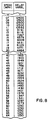
- the various required delay variables between the maximum and minimum speeds can be calculated in advance, and stored in a look-up table. For example, a corresponding value could be stored for every mile per hour difference, as shown in FIG. 8.
- the processor obtains the delay variable from the table by first rounding the speed to a value that corresponded to the resolution of the table, converting the value to an address of the appropriate memory location, and reading the value stored at that address.
- a different linear function may be used to provide the formula or values in the look-up table.
- any linear or nonlinear function can be utilized for corresponding the frequency of the flashing light with the speed of the vehicle.
- any of the circuits described herein If instead it is desired to increase the frequency in a non-linear manner (exponentially, logarithmically, or by some other function), then an operational amplifier or the like arranged to output the desired voltage as a function of the input voltage would achieve the appropriate result in an analog circuit. If the microprocessor-based circuit of FIG. 4 is used, then altering the values stored in the look-up table (or the formula employed to calculate the values) provides the appropriate frequency as a function of vehicle speed.
- the microprocessor 60 loops (or otherwise waits) for the appropriate delay time as shown in step 116 before toggling the output bit in step 118.
- the variable speed signalling device 20 may alternatively comprise a sound source such as an audible tone generator connected to drive a speaker, horn, siren or the like.
- the sound source generates at least one audible tone that may be sounded and turned off intermittently. If two distinguishable audio tones are used, the tones can be alternately sounded, or swept between (for example like a musical portamento or glissando). For example, this may be accomplished by ramping a voltage into a voltage to frequency converter, and driving a speaker with the varying frequency. In this situation, the ramp rate is determined by the vehicle speed.
- FIG. 9 illustrates two frequency sources (oscillators) 70, 72 arranged to drive a speaker in alternating tones wherein the rate of alternating therebetween depends on the speed of the vehicle.
- FIG. 9 assumes that the voltage output by the vehicle speed detector is clamped and otherwise made appropriately available as previously described with reference to FIGs. 1-3.
- the speed-dependent voltage is converted (by frequency-to-voltage converter 36) to a frequency for alternating between the sources.
- This frequency of alternation drives a relay 74 or the like via driver 28, which switches the relay contacts between a first oscillator 70 set at frequency A and a second oscillator 72 set at frequency B.
- the relay 74 is driven, the outputs of the oscillators 70, 72 are alternately applied to an audio driver 76 or the like which drives the speaker 24c.
- the repetition rate of alternating, sweeping or turning the sound on-and-off varies in either direct or inverse proportion to the speed of the moving vehicle between minimum and maximum limits.
- the audio frequency of the tone for example 440 hertz
- tones for example 500 hertz to 1500 hertz
- the repetition rate of switching or sweeping between the tones or turning a single tone on-and-off intermittently is what is varied.
- FIG. 10 illustrates one circuit for selectively influencing the ultimate broadcast signalling frequency, such as for the purpose of slightly raising the frequency from its usual rate when conditions are icy.
- a conventional operational amplifier-based adder circuit 80 is provided.
- the illustrated circuit presupposes that an appropriate negative voltage is available, but of course conventional biasing techniques may alternately be employed.
- the voltage from the detector 32 is clamped between maximum and minimum values by diodes 40 and 46 as previously described, and fed into the adding circuit 80 through a resistor 82 of appropriate value.
- a switch 84 is actuated to feed an augmented voltage into the adding circuit 80 through resistor 86.
- the switch 84 may be either manually or automatically actuated in response to a sensed external condition.
- the currents resulting from the voltages through resistors 82 and 86 are fed into an operational amplifier 88 arranged with a feedback resistor 90 to act as a conventional adder.
- the amount of gain or attenuation of each input depends on the ratio of the value of its input resistor, 82 or 84, relative to the value of the feedback resistor 90.
- a one-to-one ratio of resistor 82 to feedback resistor 90 renders neither gain nor attenuation, so the magnitude of the detector voltage is unchanged by the adder circuit 80.
- a one-to-twelve ratio of resistor 86 to feedback resistor 90 adds one volt to the output of operational amplifier 88 if directly connected to twelve volts, i.e., the speed-dependent detector output voltage will be increased by one volt.
- an inverting voltage follower 92 is provided to reinvert to positive voltage as needed.
- this adder circuit 80 may be utilized in combination with any type of signalling means, such as the light sources 24a and 24b described in FIGs. 1-3 or the alternating frequency circuit of FIG. 9, the circuit illustrated in FIG. 10 uses the output frequency to drive a speaker 24c.
- the voltage from the adder circuit 80 is converted to a frequency by voltage to frequency converter 36.
- the output frequency is an audio frequency and the driver 28 directly drives the speaker 24c whenever switch 44 is closed.
- the addition of voltage according to driving conditions is accommodated by including programming steps to add a value to the detected input voltage read in before the delay loop calculation or look-up is performed, or by subtracting a value from the delay-loop counter variable once obtained.
- the flash rate versus vehicle speed curve can essentially be tailored to any desirable shape in accordance with the conditions.
- various lights, patterns and the like can further enhance the system.
- a police vehicle might have a blue light flashing at a fixed frequency and a white light flashing at a speed proportional to the speed of the vehicle. Since this provides a viewer with a reference rate, the speed of the vehicle is easier to determine at each moment.
- Duty cycle is also generally adjustable, for example to indicate direction (long on, short off if in front of viewer, short on, long off if behind viewer) and so on.
- the present invention has been described primarily with respect to signalling devices that are directly observable by humans, there is no intent to limit the invention to visible lights and audible tones. Indeed, the present invention contemplates any manner of broadcasting speed-dependent information from an emergency vehicle.
- the signalling device of the vehicle may be arranged to broadcast speed-dependent information on RF carrier frequencies for reception by a dedicated receiving device or the like.
- commonly assigned U.S. Patent Application Serial No. 08/286,624, filed August 5, 1994 is hereby incorporated by reference.
- a method and apparatus for increasing the effectiveness of emergency signalling devices on vehicles by varying the frequency of the device in dependence on the speed of the vehicle.
- the method and apparatus enables an observer to determine the speed of a vehicle by observing signals produced by the signalling device, which preferably vary between a maximum and minimum frequency rate.
Landscapes
- Engineering & Computer Science (AREA)
- Mechanical Engineering (AREA)
- Lighting Device Outwards From Vehicle And Optical Signal (AREA)
- Non-Portable Lighting Devices Or Systems Thereof (AREA)
Description
Claims (14)
- An emergency lighting device (20) for mounting to a surface of a motor vehicle, the device comprising: a base (22) for mounting to the surface of the motor vehicle; a flashing light (24) mounted to the base; a light transmissive housing (26) supported by the base for enclosing and protecting the flashing light; a detector (32) for detecting the speed of the vehicle; and circuitry (42, 40, 46, 36; 42, 40, 46, 54, 30, 56; 66, 60, 68) responsive to the detector (32) for controlling a flash rate of the flashing light (24) so that the rate varies with the speed of the vehicle in accordance with a predetermined relationship between minimum and maximum visibly discernible flash rates.
- An emergency lighting device as set forth in claim 1 wherein the light transmissive housing (26) is a light bar housing and the base (22) includes a mounting apparatus for securing the emergency lighting device (20) to a roof of the motor vehicle.
- An emergency lighting device as set forth in claim 1 wherein the varying flash rate of the flashing light (24) is linearly proportional to the speed of the vehicle between predetermined minimum and maximum speeds, and the detector (32) includes means for detecting the minimum and maximum speeds of the vehicle.
- An emergency lighting device as set forth in claim 3 wherein the minimum vehicle speed is approximately zero.
- An emergency lighting device as set forth in claim 1 wherein the varying flash rate of the flashing light (24) is related to the speed of the vehicle in a non-linear relationship between predetermined minimum and maximum speeds.
- The emergency lighting device as set forth in claim 1 further comprising circuitry (36) for selectively modifying the flash rate of the flashing light.
- The emergency lighting device as set forth in claim 1 wherein the circuitry includes a microprocessor (60).
- A method of operating emergency signalling devices mounted to a motor vehicle, the method comprising the steps of:generating an emergency signal that is sensed by an observer as having a cyclical characteristic;maintaining a repetition rate of the cyclical characteristic of the emergency signal at a minimum value for speeds of the motor vehicle below a predetermined lower limit;maintaining the repetition rate of the cyclical characteristic of the emergency signal at a maximum value for speeds of the motor vehicle above a predetermined upper limit, where the cyclical characteristic is discernible to the observer at the maximum value; andadjusting the repetition rate of the emergency signal to a value proportional to the repetition rate and the speed of the vehicle for speeds between the lower and upper limits.
- A method as set forth in claim 8 wherein the proportional relationship is a linear relationship.
- A method as set forth in claim 8 wherein the proportional relationship is a non-linear relationship.
- The method as set forth in claim 8 further comprising the step of varying the repetition rate of the emergency signal in response to external driving conditions.
- An emergency signalling device for a vehicle, comprising: a signalling device (20) for broadcasting emergency signals; mounting means for connecting the signalling device to the vehicle; a detector (32) for converting the speed of the vehicle to a DC voltage having an amplitude corresponding to the speed of the vehicle; circuitry (36) for converting the DC voltage to a second electrical signal having a repetition rate corresponding to the speed of the vehicle; circuitry (40, 46) for maintaining the repetition rate between maximum and minimum rates, where the maximum and minimum rates are visibly discernible to a human observer; and means (28) connecting the second electrical signal to the signalling device for broadcasting emergency signals having a variable range of repetition rates corresponding to the speed of the vehicle between maximum and minimum signalling rates.
- The device of claim 12 wherein the electrical signal from the detector (32) comprises a DC voltage having an amplitude corresponding to the vehicle speed, and wherein the circuitry for converting the first electrical signal to the second electrical signal includes a voltage-to-frequency converter (36).
- The device of claim 12 wherein the signalling device (20) comprises a speaker (24c) connected to a source (70, 72) of at least two distinct audio frequencies.
Applications Claiming Priority (3)
| Application Number | Priority Date | Filing Date | Title |
|---|---|---|---|
| US08/310,637 US6211779B1 (en) | 1994-09-22 | 1994-09-22 | Variable speed warning device |
| PCT/US1995/010748 WO1996009188A1 (en) | 1994-09-22 | 1995-08-24 | Variable speed warning device |
| US310637 | 1999-05-12 |
Publications (2)
| Publication Number | Publication Date |
|---|---|
| EP0782511A1 EP0782511A1 (en) | 1997-07-09 |
| EP0782511B1 true EP0782511B1 (en) | 2000-01-05 |
Family
ID=23203441
Family Applications (1)
| Application Number | Title | Priority Date | Filing Date |
|---|---|---|---|
| EP95930265A Expired - Lifetime EP0782511B1 (en) | 1994-09-22 | 1995-08-24 | Variable speed warning device |
Country Status (6)
| Country | Link |
|---|---|
| US (1) | US6211779B1 (en) |
| EP (1) | EP0782511B1 (en) |
| AU (1) | AU3371695A (en) |
| CA (1) | CA2197300C (en) |
| DE (1) | DE69514374T2 (en) |
| WO (1) | WO1996009188A1 (en) |
Families Citing this family (18)
| Publication number | Priority date | Publication date | Assignee | Title |
|---|---|---|---|---|
| US6824312B2 (en) * | 2001-06-04 | 2004-11-30 | Adc Telecommunications, Inc. | Telecommunications chassis and module |
| US7916152B2 (en) * | 2002-11-01 | 2011-03-29 | Tenebraex Corporaton | Technique for enabling color blind persons to distinguish between various colors |
| US20110229023A1 (en) * | 2002-11-01 | 2011-09-22 | Tenebraex Corporation | Technique for enabling color blind persons to distinguish between various colors |
| US7145571B2 (en) * | 2002-11-01 | 2006-12-05 | Tenebraex Corporation | Technique for enabling color blind persons to distinguish between various colors |
| US20050056201A1 (en) * | 2003-02-14 | 2005-03-17 | Jones Peter W. J. | System and method for conveying enhanced visually perceptible cues to an observer |
| US20040257212A1 (en) * | 2003-06-18 | 2004-12-23 | Wen-Chang Wang | Warning device able to set speeds of an automobile |
| WO2005013806A2 (en) * | 2003-08-06 | 2005-02-17 | Tenebraex Corporation | Techniques for diagnosing and aiding color vision |
| DE102004022718A1 (en) * | 2004-05-07 | 2005-11-24 | Hella Kgaa Hueck & Co. | Method for controlling a flashing light for motor vehicles |
| US7337750B2 (en) * | 2004-11-05 | 2008-03-04 | Robert L. Drake | Animal deterrent device |
| TWI239916B (en) * | 2005-01-18 | 2005-09-21 | Lite On Automotive Corp | Security apparatus for motor vehicles |
| WO2007018532A1 (en) * | 2005-08-03 | 2007-02-15 | Boston Scientific Scimed, Inc. | Systems, devices and methods relating to a shape resilient sling-like support for treating urinary incontinence |
| US20080261183A1 (en) * | 2007-04-23 | 2008-10-23 | Steven Donaldson | Device for treating stuttering and method of using the same |
| RU2346832C1 (en) * | 2008-02-08 | 2009-02-20 | Андрей Александрович Севастьянов | Light alarm on outside door handle of automobile |
| EP2714468A4 (en) * | 2011-05-24 | 2015-05-20 | Code 3 Inc | Programmable control for siren and lights |
| US20160009222A1 (en) * | 2014-07-09 | 2016-01-14 | Eugene Taylor | Emergency alert audio interception |
| WO2017091240A1 (en) * | 2015-11-25 | 2017-06-01 | Houss Max | Signal u-turn |
| JP6828505B2 (en) * | 2017-02-23 | 2021-02-10 | アイシン精機株式会社 | Notification device for mobile objects |
| JP2021131234A (en) * | 2020-02-18 | 2021-09-09 | 富士フイルムビジネスイノベーション株式会社 | Light emitting device and program |
Family Cites Families (32)
| Publication number | Priority date | Publication date | Assignee | Title |
|---|---|---|---|---|
| US1543704A (en) | 1921-05-16 | 1925-06-30 | Harry C Evelyn | Signal for motor vehicles |
| US1589071A (en) | 1922-01-13 | 1926-06-15 | Electric signaling system | |
| US2681957A (en) | 1950-01-13 | 1954-06-22 | Gen Motors Corp | Air velocity responsive snap action switch |
| US2794082A (en) | 1953-03-02 | 1957-05-28 | Louis H Germaine | Automotive signalling system |
| US2903684A (en) | 1957-03-06 | 1959-09-08 | Paul J Stine | Speed alarm indicator for automotive vehicles |
| US3431556A (en) | 1966-03-15 | 1969-03-04 | Marvin D Johnson | Deceleration warning signal system |
| AT311814B (en) | 1968-03-18 | 1973-12-10 | Daimler Benz Ag | Brake light signaling device for motor vehicles |
| US3631390A (en) * | 1969-11-21 | 1971-12-28 | Thomas S B Murphy | Vehicle movement condition safety light system |
| US3691525A (en) | 1971-05-27 | 1972-09-12 | Rudolph M Mcclellan Sr | Vehicle speed indicator system |
| US3829828A (en) | 1971-05-28 | 1974-08-13 | Ko An Inc | Speed responsive timing circuit for vehicle light operation |
| US3774152A (en) | 1971-11-01 | 1973-11-20 | J Tandy | Speed controlled taillight system for a vehicle |
| US3748642A (en) | 1972-05-02 | 1973-07-24 | Ford Motor Co | External high speed warning system for an automotive vehicle |
| US3860905A (en) | 1972-07-05 | 1975-01-14 | Mario Guerini | Speed indicator and speed signalling device for vehicles in general |
| US3771122A (en) | 1972-08-11 | 1973-11-06 | Gen Motors Corp | Motor vehicle automatic hazard warning system |
| FR2230187A5 (en) | 1973-05-16 | 1974-12-13 | Barriere Jeannine | Variable speed flasher apparatus for car - has pinion assembly adapting flash rate so is proportional to speed of car |
| US3919689A (en) * | 1974-06-03 | 1975-11-11 | Towmotor Corp | Vehicle speed indicator system |
| DE2447241A1 (en) | 1974-10-03 | 1976-04-08 | Zeidler Martin Dr Med | Speed sensitive brake lights - has internal gearing to measure speedometer gearing and drive circuit breaker cam |
| US4019171A (en) | 1974-12-16 | 1977-04-19 | Sears, Roebuck And Co. | Safety lighting system |
| US3930225A (en) | 1975-01-14 | 1975-12-30 | Roxie Mollico | Vehicle safety indicating apparatus |
| US3952689A (en) | 1975-03-12 | 1976-04-27 | The Raymond Lee Organization, Inc. | Vehicle registration and velocity display device |
| US4189706A (en) | 1978-03-06 | 1980-02-19 | Knox Leonard S | Vehicle control for multiple speeds |
| US4281311A (en) | 1979-06-07 | 1981-07-28 | Federal Signal Corporation | Method and apparatus for increasing effective light intensity of a rotating light |
| US4320384A (en) * | 1979-12-13 | 1982-03-16 | Carlson Robert W | Vehicle acceleration/deceleration warning system |
| US4357594A (en) * | 1980-06-02 | 1982-11-02 | Traffic Safety Devices Company | Vehicular hazard warning system |
| US4491824A (en) | 1982-01-11 | 1985-01-01 | Chiou Nan Mu | Safety indicator for vehicles |
| US4635039A (en) | 1983-05-16 | 1987-01-06 | Federal Signal Corporation | Low drag warning system for emergency vehicles |
| US5140304A (en) | 1986-04-22 | 1992-08-18 | Miller Jack V | Siren sound sychronized light bar system |
| US4831357A (en) | 1986-04-22 | 1989-05-16 | Miller Jack V | Siren sound sychronized light bar system |
| GB2222919A (en) | 1988-09-20 | 1990-03-21 | Safety Equipment Public Inc | Apparatus and methods for controlling a signal device |
| US4894641A (en) * | 1989-01-24 | 1990-01-16 | Cotron Corporation | Real-time speed display apparatus |
| US5012221A (en) | 1989-03-24 | 1991-04-30 | Siren Sounds, Inc. | Emergency vehicle audible warning system and method |
| US5296840A (en) * | 1990-05-25 | 1994-03-22 | Federal Signal Corporation | Programmable emergency signalling system for a vehicle |
-
1994
- 1994-09-22 US US08/310,637 patent/US6211779B1/en not_active Expired - Fee Related
-
1995
- 1995-08-24 DE DE69514374T patent/DE69514374T2/en not_active Expired - Fee Related
- 1995-08-24 AU AU33716/95A patent/AU3371695A/en not_active Abandoned
- 1995-08-24 WO PCT/US1995/010748 patent/WO1996009188A1/en not_active Ceased
- 1995-08-24 CA CA002197300A patent/CA2197300C/en not_active Expired - Fee Related
- 1995-08-24 EP EP95930265A patent/EP0782511B1/en not_active Expired - Lifetime
Also Published As
| Publication number | Publication date |
|---|---|
| AU3371695A (en) | 1996-04-09 |
| DE69514374T2 (en) | 2000-06-08 |
| WO1996009188A1 (en) | 1996-03-28 |
| EP0782511A1 (en) | 1997-07-09 |
| US6211779B1 (en) | 2001-04-03 |
| CA2197300C (en) | 2000-04-11 |
| DE69514374D1 (en) | 2000-02-10 |
| CA2197300A1 (en) | 1996-03-28 |
Similar Documents
| Publication | Publication Date | Title |
|---|---|---|
| US6211779B1 (en) | Variable speed warning device | |
| US5325096A (en) | Smart blind spot sensor | |
| US4626850A (en) | Vehicle detection and collision avoidance apparatus | |
| EP0239545B1 (en) | System for monitoring and indicating acoustically the operating conditions of a motor vehicle | |
| US5017904A (en) | Braking indicator system | |
| US4631542A (en) | Police radar warning receiver with mute function | |
| US3691525A (en) | Vehicle speed indicator system | |
| KR870001533A (en) | Automatic Collision Avoidance and / or Airbag Placement Radar | |
| CA2129234A1 (en) | Motor vehicle display system and ranging device | |
| JPH0732948A (en) | Pseudo-running sound generator for electric vehicles | |
| US5788336A (en) | Anti-lock brake warning system | |
| EP0807548A3 (en) | Electronic flasher system | |
| US6271746B1 (en) | Method and devices for controlling the use of an automotive horn | |
| EP0655980A1 (en) | Multi-sound vehicle horn system | |
| GB2319124A (en) | Indicating state of motion of a vehicle; vehicle ranging device | |
| JPH11321459A (en) | Alarm sound device for vehicle | |
| JPS6094845A (en) | Warning device for vehicle | |
| KR960017330A (en) | Alarm sound control device of vehicle and its method | |
| KR960010157B1 (en) | Automotive volume control device | |
| KR0115988Y1 (en) | Overspeed alarm apparatus | |
| JPH02271278A (en) | Collision preventing apparatus of automobile | |
| KR100206208B1 (en) | Warning device | |
| JPH03176800A (en) | Alarming device for short distance between vehicles | |
| JP3227110B2 (en) | In-vehicle microwave detector | |
| KR960038698A (en) | Vehicle warning device in front of obstacle detection |
Legal Events
| Date | Code | Title | Description |
|---|---|---|---|
| PUAI | Public reference made under article 153(3) epc to a published international application that has entered the european phase |
Free format text: ORIGINAL CODE: 0009012 |
|
| 17P | Request for examination filed |
Effective date: 19970321 |
|
| AK | Designated contracting states |
Kind code of ref document: A1 Designated state(s): DE FR GB |
|
| 17Q | First examination report despatched |
Effective date: 19971219 |
|
| GRAG | Despatch of communication of intention to grant |
Free format text: ORIGINAL CODE: EPIDOS AGRA |
|
| GRAG | Despatch of communication of intention to grant |
Free format text: ORIGINAL CODE: EPIDOS AGRA |
|
| GRAH | Despatch of communication of intention to grant a patent |
Free format text: ORIGINAL CODE: EPIDOS IGRA |
|
| GRAH | Despatch of communication of intention to grant a patent |
Free format text: ORIGINAL CODE: EPIDOS IGRA |
|
| GRAA | (expected) grant |
Free format text: ORIGINAL CODE: 0009210 |
|
| AK | Designated contracting states |
Kind code of ref document: B1 Designated state(s): DE FR GB |
|
| REF | Corresponds to: |
Ref document number: 69514374 Country of ref document: DE Date of ref document: 20000210 |
|
| RBV | Designated contracting states (corrected) |
Designated state(s): DE FR GB |
|
| ET | Fr: translation filed | ||
| PGFP | Annual fee paid to national office [announced via postgrant information from national office to epo] |
Ref country code: GB Payment date: 20000830 Year of fee payment: 6 |
|
| PGFP | Annual fee paid to national office [announced via postgrant information from national office to epo] |
Ref country code: DE Payment date: 20000904 Year of fee payment: 6 |
|
| PGFP | Annual fee paid to national office [announced via postgrant information from national office to epo] |
Ref country code: FR Payment date: 20000912 Year of fee payment: 6 |
|
| PLBE | No opposition filed within time limit |
Free format text: ORIGINAL CODE: 0009261 |
|
| STAA | Information on the status of an ep patent application or granted ep patent |
Free format text: STATUS: NO OPPOSITION FILED WITHIN TIME LIMIT |
|
| 26N | No opposition filed | ||
| PG25 | Lapsed in a contracting state [announced via postgrant information from national office to epo] |
Ref country code: GB Free format text: LAPSE BECAUSE OF NON-PAYMENT OF DUE FEES Effective date: 20010824 |
|
| GBPC | Gb: european patent ceased through non-payment of renewal fee |
Effective date: 20010824 |
|
| PG25 | Lapsed in a contracting state [announced via postgrant information from national office to epo] |
Ref country code: DE Free format text: LAPSE BECAUSE OF NON-PAYMENT OF DUE FEES Effective date: 20020501 |
|
| PG25 | Lapsed in a contracting state [announced via postgrant information from national office to epo] |
Ref country code: FR Free format text: LAPSE BECAUSE OF NON-PAYMENT OF DUE FEES Effective date: 20030430 |
|
| REG | Reference to a national code |
Ref country code: FR Ref legal event code: ST |
|
| PG25 | Lapsed in a contracting state [announced via postgrant information from national office to epo] |
Ref country code: FR Free format text: LAPSE BECAUSE OF NON-PAYMENT OF DUE FEES Effective date: 20010831 |