EP0782125A2 - Method and apparatus for transferring heat from transducer array of ultrasonic probe - Google Patents
Method and apparatus for transferring heat from transducer array of ultrasonic probe Download PDFInfo
- Publication number
- EP0782125A2 EP0782125A2 EP96309274A EP96309274A EP0782125A2 EP 0782125 A2 EP0782125 A2 EP 0782125A2 EP 96309274 A EP96309274 A EP 96309274A EP 96309274 A EP96309274 A EP 96309274A EP 0782125 A2 EP0782125 A2 EP 0782125A2
- Authority
- EP
- European Patent Office
- Prior art keywords
- heat
- cable
- probe
- transducer
- heat conductive
- Prior art date
- Legal status (The legal status is an assumption and is not a legal conclusion. Google has not performed a legal analysis and makes no representation as to the accuracy of the status listed.)
- Granted
Links
Images


Classifications
-
- A—HUMAN NECESSITIES
- A61—MEDICAL OR VETERINARY SCIENCE; HYGIENE
- A61B—DIAGNOSIS; SURGERY; IDENTIFICATION
- A61B8/00—Diagnosis using ultrasonic, sonic or infrasonic waves
- A61B8/54—Control of the diagnostic device
- A61B8/546—Control of the diagnostic device involving monitoring or regulation of device temperature
-
- A—HUMAN NECESSITIES
- A61—MEDICAL OR VETERINARY SCIENCE; HYGIENE
- A61B—DIAGNOSIS; SURGERY; IDENTIFICATION
- A61B8/00—Diagnosis using ultrasonic, sonic or infrasonic waves
- A61B8/44—Constructional features of the ultrasonic, sonic or infrasonic diagnostic device
- A61B8/4483—Constructional features of the ultrasonic, sonic or infrasonic diagnostic device characterised by features of the ultrasound transducer
-
- G—PHYSICS
- G10—MUSICAL INSTRUMENTS; ACOUSTICS
- G10K—SOUND-PRODUCING DEVICES; METHODS OR DEVICES FOR PROTECTING AGAINST, OR FOR DAMPING, NOISE OR OTHER ACOUSTIC WAVES IN GENERAL; ACOUSTICS NOT OTHERWISE PROVIDED FOR
- G10K11/00—Methods or devices for transmitting, conducting or directing sound in general; Methods or devices for protecting against, or for damping, noise or other acoustic waves in general
- G10K11/004—Mounting transducers, e.g. provided with mechanical moving or orienting device
Definitions
- This invention generally relates to probes used in ultrasonic imaging of the human anatomy.
- the invention relates to techniques for limiting the build-up of transducer-generated heat on the exterior of an ultrasound probe.
- a conventional ultrasonic probe comprises a transducer pallet which must be supported within the probe housing.
- a conventional transducer pallet 2 comprises a linear array 4 of narrow transducer elements.
- Each transducer element is made of piezoelectric material.
- the piezoelectric material is typically lead zirconate titanate (PZT), polyvinylidene difluoride, or PZT ceramic/polymer composite.
- each transducer element has a metallic coating on opposing front and back faces to serve as electrodes.
- the metallic coating on the front face serves as the ground electrode.
- the ground electrodes of the transducer elements are all connected to a common ground.
- the metallic coating on the back face serves as the signal electrode.
- the signal electrodes of the transducer elements are connected to respective electrical conductors formed on a flexible printed circuit board (PCB) 6.
- PCB flexible printed circuit board
- the signal and ground electrodes of the piezoelectric transducer elements are connected to an electrical source having an impedance Z,.
- the material of the piezoelectric element compresses at a frequency corresponding to that of the applied voltage, thereby emitting an ultrasonic wave into the media to which the piezoelectric element is coupled.
- the material of the piezoelectric element compresses at a frequency corresponding to that of the applied voltage, thereby emitting an ultrasonic wave into the media to which the piezoelectric element is coupled.
- an ultrasonic wave impinges on the material of the piezoelectric element, the latter produces a corresponding voltage across its terminals and the associated electrical load component of the electrical source.
- the transducer pallet 2 also comprises a mass of suitable acoustical damping material having high acoustic losses positioned at the back surface of the transducer element array 4.
- Backing layer 12 is acoustically coupled to the rear surface of the transducer elements, via the acoustically transparent PCB 6, to absorb ultrasonic waves that emerge from the back side of each element so that those waves will not be partially reflected and interfere with the ultrasonic waves propagating in the forward direction.
- each transducer element of array 4 is covered with at least one acoustic impedance matching layer 8.
- the impedance matching layer 8 transforms the high acoustic impedance of the transducer elements to the low acoustic impedance of the human body and water, thereby improving the coupling with the medium in which the emitted ultrasonic waves will propagate.
- the transducer element array, backing layer and acoustic impedance matching layer are all bonded together in a stack-up arrangement, as seen in FIG. 1.
- the transducer stack-up must be held securely within the probe housing. Typically, this is accomplished by securing the transducer stack-up within a four-sided array case (not shown), i.e., a "box" having four side walls but no top or bottom walls.
- the array case is made of electrically conductive material and provides a common ground for connection with the ground electrodes of the transducer elements.
- the transducer stack-up is inserted into a recess in the array case until the bottom surface of the acoustic impedance matching layer 8 is flush with the bottom edge of the array case.
- the transducer stack-up is conventionally bonded inside the array case using epoxy. Then a second acoustic impedance matching layer is conventionally bonded to those flush bottom surfaces.
- each transducer element produces a burst of ultrasonic energy when energized by a pulsed waveform produced by a transmitter (not shown).
- the pulses are transmitted to the transducer elements via the flexible PCB 6.
- This ultrasonic energy is transmitted by the probe into the tissue of the object under study.
- the ultrasonic energy reflected back to transducer element array 4 from the object under study is converted to an electrical signal by each receiving transducer element and applied separately to a receiver (not shown).
- the release of acoustic energy during transmission creates a thermal build-up in the probe due to acoustic losses being converted into heat.
- the amount of heat that can be allowed to build up on the exterior of an ultrasound probe must be within prescribed limits. Typically the limit is that the temperature on the patient contact surface of the probe cannot exceed 41°C or 16°C above ambient temperature, whichever is smaller. Most of the heat tends to build up immediately around the transducer elements, which are necessarily situated in the probe very close to the body of the patient being examined.
- transducer pallet 2 During assembly of an ultrasonic probe incorporating the structure of FIG. 1, transducer pallet 2 must be secured within the probe housing.
- the interior volume of the probe housing surrounding the transducer pallet is filled with thermally conductive potting material, e.g., heat-conductive ceramic granules embedded in epoxy.
- the potting material stabilizes the construction and assists in dissipating heat, generated during pulsation of the transducer element array, away from the probe surface/transducer face toward the interior/rear of the probe.
- Ultrasonic transducer technology is rapidly evolving towards probes with higher element counts. This in turn requires more cabling and lighter-weight materials, and challenges the manufacturability of the interconnect between the individual elements and the ultrasonic imaging system. Added to this strain on the packaging technology is the availability of high levels of circuit integration in semiconductors. Because of the electrical impedance mismatch between the small elements in the transducer and the sensing electronics in the system, a number of investigators have developed means to provide active electronics within the transducer handle. As electronic technology advances, it is expected that more active circuitry will be placed as near to the source of the detected signal as possible.
- the above-described use of heat pipes will no longer be sufficient to handle the heat load within the transducer.
- the heat load dissipated by the simple devices available today is approximately 1 W. If preamplifiers are introduced into the system which dissipate 10 mW in a quiescent mode, the heat load will be increased by 2 W for a 200-element probe. Because the current designs are sometimes limited by the temperature of the patient contact area, there is little margin to accommodate this type of thermal output increase. Thus, there is a need to provide thermal transfer mechanisms capable of dissipating greater amounts of heat.
- the present invention is a device for improving thermal transfer inside an ultrasound probe and reducing heat build-up near the transducer face.
- the invention is based on the concept of using the coaxial cable as a tool in managing the thermal problem created by the incorporation of active electronics in the handle of an ultrasonic probe.
- the cable components are used as heat pipes which conduct heat out of the probe handle. These heat pipes are coupled to an internal heat pipe, made of a sheet or plate of heat conductive material, which is embedded in the backing layer material of a transducer pallet.
- heat generated by the transducer array can be transferred, via the internal heat pipe and the cable heat pipes, away from the probe surface which contacts the patient.
- the cable assembly in an ultrasonic probe is composed of multiple coaxial cables bundled together and covered with an overall braided shield.
- Each individual coaxial cable comprises a plurality of individual conductors surrounded by a twisted shield.
- these heat conductive structures can serve as thermal transfer devices when thermally coupled to an internal heat pipe of the probe handle.
- a heat conductive structure can be embedded in the overall shield braid of the cable.
- Suitable heat conductive structures include thread or wire made of material having a high coefficient of thermal conductivity, as well as narrow tubing filled with heat conductive fluid.
- inlet and return flow paths for cooling fluid are incorporated in the cable.
- the inlet and return flow paths inside the cable are respectively connected to the inlet and outlet of a flow path which is in heat conductive relationship with an internal heat pipe in the probe handle.
- the cooling fluid is pumped from the cable return flow path to the cable inlet flow path.
- recirculation can be induced by cooling a portion of the cable flow path formed by connecting the cable return flow path directly to the cable input flow path, thereby generating a thermal gradient which draws heat out of the probe handle.
- the invention solves the problem of how to transfer heat out of the probe handle in a manner so that the temperature of the probe part which contacts the patient does not exceed a predetermined upper limit.
- the invention provides a mechanism for dissipating heat generated inside the probe handle in a manner that leaves the patient unaware of the heating effect.
- FIG. 1 is a schematic exploded view of parts of a conventional transducer pallet for use in an ultrasonic probe.
- FIG. 2 is a schematic diagram showing the structure of an ultrasonic probe in accordance with a first preferred embodiment of the invention wherein the transducer pallet is thermally coupled to the cable via a soldered internal heat pipe.
- FIG. 3 is a schematic diagram showing on a magnified scale the handle of the ultrasonic probe shown in FIG. 2.
- FIGS. 4A through 4F are schematic diagrams showing six variations of the internal heat pipe configuration in accordance with the preferred embodiments of the invention.
- FIG. 5 is a schematic diagram showing the probe handle of an ultrasonic probe in accordance with a second preferred embodiment of the invention wherein the transducer pallet is thermally coupled to the cable via a passive fluid coupling.
- FIGS. 6A and 6B are schematic diagrams showing the probe handle and system connector, respectively, of an ultrasonic probe in accordance with a third preferred embodiment of the invention wherein the transducer pallet is thermally coupled to the cable via an active fluid coupling.
- FIG. 7 is a schematic sectional view showing the cable of an ultrasonic probe in accordance with a fourth preferred embodiment of the invention wherein heat pipes are embedded in a cable shield.
- FIG. 8A is a schematic diagram showing the armored cable of an ultrasonic probe in accordance with a fifth preferred embodiment of the invention wherein heat pipes are molded into the cable armor.
- FIG. 8B is a sectional view of the armor incorporated in the probe shown in FIG. 8A.
- FIG. 9 is a schematic diagram showing the probe handle of an ultrasonic probe in accordance with a sixth preferred embodiment of the invention wherein the transducer pallet is thermally coupled to the cable via a semiconductor chiller.
- an ultrasound probe in accordance with the preferred embodiment of the invention comprises a probe handle 14 connected to one end of a cable 16 and a system connector 18 connected to the other end of the cable. Means 20 and 22 for relieving stress are provided at the cable/housing and system connector/cable connections, respectively.
- the probe handle 14 comprises a plastic shell 24 which houses a conventional transducer pallet 2.
- the system connector comprises a plastic housing 26 in which a PCB 28 is mounted.
- the signal electrodes of the transducer array are electrically connected to PCB 28 via flexible PCB 6, signal wiring 30 and a multiplicity of coaxial cables in cable 16.
- the probe handle 14 in accordance with a first preferred embodiment of the invention comprises a transducer pallet 2 mounted in plastic shell 24.
- the pallet is arranged so that the front face of the transducer array is acoustically coupled to a cylindrical focusing lens 32 which contacts the patient.
- the transducer pallet 2 and focusing lens 32 are mounted inside plastic shell 24 by adhesively bonding the perimeter of lens 32 in an opening of corresponding shape formed in one end of shell 24.
- the other end of shell 24 is attached to the cable jacket 34.
- at least one internal heat pipe 36 made of a material having a relatively high coefficient of thermal conductivity, is thermally coupled to a central portion of the transducer pallet.
- external heat pipes 38a and 38b (which may also serve the function of providing electromagnetic shielding) are placed in heat conductive relationship with the lateral periphery of the pallet.
- the signal electrodes of the transducer array are electrically connected to the central conductors (not shown in FIG. 3) of respective coaxial cables via conductive traces formed on flexible PCB 6 and via signal wiring 30.
- the cable overall (braided) shield 40 is brought into the probe handle 14 through the cable strain relief and directly soldered to the heat pipe structure 36 that is connected to pallet 2.
- the solder bead is indicated by numeral 42 in FIG. 3. This provides the most direct and effective method of piping heat from the source into the extended heat sink formed by the cable.
- the external heat pipes 38a and 38b are soldered to the cable overall shield 40.
- the cable comprises a bundle of coaxial cables surrounded by the overall shield.
- the internal heat pipe can be thermally coupled to the shield braid of each coaxial cable in the bundle.
- the internal heat pipe 36 may comprise a flexible sheet or stiff plate of heat conductive material having one of the configurations depicted in FIGS. 4A, 4B and 4C.
- the configurations depicted in FIGS. 4B and 4C comprise respective flat heat pipes 36' and 36", each having a comb-like structure which is thermally coupled to the transducer pallet by embedding the comb fingers in the backing material.
- the transducer pallet 2 is thermally coupled to the cable shield braid 40 via a passive fluid coupling comprising a cable fluid path 44 incorporated in the cable bundle, a fluid channel 46 mounted on and thermally coupled to the internal heat pipe 36, and a coupling joint 48 for connecting cable fluid path 44 to fluid channel 46.
- the fluid channel 46 may take the form of a U-shaped pipe as seen in FIG. 4D, while the cable fluid path is a pipe incorporated in the cable bundle and thermally coupled to the cable shield braid.
- the coupling joint 48 takes the form of a straight pipe in fluid communication with the ends of the legs of the U-shaped fluid channel and with an end of the cable fluid path 44, as seen in FIG. 4D.
- Each pipe 44, 46 and 48 may be a plastic or metal tube filled with a fluid having a relatively high thermal conductivity. Liquid metals, for example, could be used in this application provided that sufficient precautions were taken to maintain patient safety.
- the pipes are passive, i.e., heat is transferred into the pipes passively and transferred throughout the cable without fluid motion.
- the transducer pallet 2 is thermally coupled to the cable shield braid 40 via an active fluid coupling comprising an input cable fluid path 50 and a return cable fluid path 52 both incorporated in the cable bundle, a fluid channel 54 mounted on and thermally coupled to the internal heat pipe 36, and coupling joints 56 and 58 for respectively connecting the input and return cable fluid paths to fluid channel 54.
- the fluid channel 54 may take the form of a U-shaped pipe as seen in FIG. 4E, while the input and return cable fluid paths are respective pipes incorporated in the cable bundle and thermally coupled to the cable shield braid.
- One end of the input cable fluid path 50 is in fluid communication with an input leg of fluid channel 54; the end of the return cable fluid path 52 is in fluid communication with an output leg of fluid channel 54.
- the input and out-put legs of fluid channel 54 may be mounted on the same side (as shown in FIG. 4E) or on opposite sides of the internal heat pipe 36 (as shown in FIG. 6A). In the latter case, part of the U-shaped fluid channel is embedded in the backing material.
- Each pipe 50, 52 and 54 may be a plastic or metal tube filled with fluid having a high thermal conductivity.
- the third preferred embodiment utilizes active movement, i.e., recirculating flow, of the cooling fluid in cooling pipes to cool the probe handle.
- This might be accomplished with a small micromotor 60 (see FIG. 6B) powered by the system.
- the micromotor 60 drives a pump 62 which pumps cooling fluid from a cooling fluid input line 64 to a cooling fluid output line 66 arranged inside the system connector 18.
- the cooling fluid input line 64 is in flow communication with the return cable fluid path 52 and the cooling fluid output line 66 is in flow communication with the input cable fluid path 50.
- pump 62, cooling fluid output line 66, input cable fluid path 50, fluid channel 54, return cable fluid path 52 and cooling fluid input line 64 form a closed circuit for recirculating flow of cooling fluid.
- recirculating flow may be driven by active cooling of a portion of the fluid circuit, thereby generating a thermal gradient which draws heat out of the probe handle. In either case, energy is expended in order to create cooling in the transducer handle.
- a variation on the active fluid coupling embodiment is to eliminate the internal heat pipe and simply embed the curved part of the U-shaped fluid channel 46 (see FIG. 4F) in the backing material.
- a plurality of heat pipes 68 are implanted in the overall braid or shield 40 of the cable assembly.
- the overall shield 40 is in the shape of a braided annulus bounded by the cable jacket 34 on an outer periphery and by an internal sheath 70 on an inner periphery.
- the internal sheath 70 surrounds a bundle of coaxial cables 72.
- Each coaxial cable in turn comprises a jacket 74, braided shielding 76, dielectric 78 and a center conductor 80 arranged in well-known manner.
- the cable shield heat pipes 68 may be circumferentially distributed at equal angular intervals around the overall shield 40.
- the heat pipes may be made of any suitable material having a high coefficient of thermal conductivity, including gold threads woven into the overall braid (selected heat pipes with high coefficients of thermal conductivity) or a tube filled with fluid.
- the bundle of coaxial cables is surrounded by a spiral armor 82.
- the armor cross section can be molded to provide one or more channels, which are filled with heat conductive material for transporting heat along the cable and away from the probe handle.
- the armor can be molded to provide input and return channels 84a, 84b for recirculating fluid used to cool the transducer pallet.
- a semiconductor chiller 86 is mounted in heat conductive relationship with the transducer pallet 2. Then an arrangement similar to that shown in FIGS. 6A and 6B is used to pipe the heat generated by the semiconductor chiller 86 to the outside environment. In this case, however, the internal heat pipe 36 is placed in heat conductive relationship with the semiconductor chiller 86, instead of being thermally coupled to the transducer pallet directly.
Landscapes
- Health & Medical Sciences (AREA)
- Life Sciences & Earth Sciences (AREA)
- Engineering & Computer Science (AREA)
- Physics & Mathematics (AREA)
- Biomedical Technology (AREA)
- Molecular Biology (AREA)
- Biophysics (AREA)
- Nuclear Medicine, Radiotherapy & Molecular Imaging (AREA)
- Pathology (AREA)
- Radiology & Medical Imaging (AREA)
- Veterinary Medicine (AREA)
- Heart & Thoracic Surgery (AREA)
- Medical Informatics (AREA)
- Public Health (AREA)
- Surgery (AREA)
- Animal Behavior & Ethology (AREA)
- General Health & Medical Sciences (AREA)
- Multimedia (AREA)
- Acoustics & Sound (AREA)
- Gynecology & Obstetrics (AREA)
- Ultra Sonic Daignosis Equipment (AREA)
- Investigating Or Analyzing Materials By The Use Of Ultrasonic Waves (AREA)
Abstract
Description
- This invention generally relates to probes used in ultrasonic imaging of the human anatomy. In particular, the invention relates to techniques for limiting the build-up of transducer-generated heat on the exterior of an ultrasound probe.
- A conventional ultrasonic probe comprises a transducer pallet which must be supported within the probe housing. As shown in FIG. 1, a
conventional transducer pallet 2 comprises alinear array 4 of narrow transducer elements. Each transducer element is made of piezoelectric material. The piezoelectric material is typically lead zirconate titanate (PZT), polyvinylidene difluoride, or PZT ceramic/polymer composite. - Typically, each transducer element has a metallic coating on opposing front and back faces to serve as electrodes. The metallic coating on the front face serves as the ground electrode. The ground electrodes of the transducer elements are all connected to a common ground. The metallic coating on the back face serves as the signal electrode. The signal electrodes of the transducer elements are connected to respective electrical conductors formed on a flexible printed circuit board (PCB) 6.
- During operation, the signal and ground electrodes of the piezoelectric transducer elements are connected to an electrical source having an impedance Z,. When a voltage waveform is developed across the electrodes, the material of the piezoelectric element compresses at a frequency corresponding to that of the applied voltage, thereby emitting an ultrasonic wave into the media to which the piezoelectric element is coupled. Conversely, when an ultrasonic wave impinges on the material of the piezoelectric element, the latter produces a corresponding voltage across its terminals and the associated electrical load component of the electrical source.
- The
transducer pallet 2 also comprises a mass of suitable acoustical damping material having high acoustic losses positioned at the back surface of thetransducer element array 4.Backing layer 12 is acoustically coupled to the rear surface of the transducer elements, via the acousticallytransparent PCB 6, to absorb ultrasonic waves that emerge from the back side of each element so that those waves will not be partially reflected and interfere with the ultrasonic waves propagating in the forward direction. - Typically, the front surface of each transducer element of
array 4 is covered with at least one acoustic impedance matching layer 8. The impedance matching layer 8 transforms the high acoustic impedance of the transducer elements to the low acoustic impedance of the human body and water, thereby improving the coupling with the medium in which the emitted ultrasonic waves will propagate. - The transducer element array, backing layer and acoustic impedance matching layer are all bonded together in a stack-up arrangement, as seen in FIG. 1. During assembly of the ultrasonic probe, the transducer stack-up must be held securely within the probe housing. Typically, this is accomplished by securing the transducer stack-up within a four-sided array case (not shown), i.e., a "box" having four side walls but no top or bottom walls. The array case is made of electrically conductive material and provides a common ground for connection with the ground electrodes of the transducer elements. The transducer stack-up is inserted into a recess in the array case until the bottom surface of the acoustic impedance matching layer 8 is flush with the bottom edge of the array case. The transducer stack-up is conventionally bonded inside the array case using epoxy. Then a second acoustic impedance matching layer is conventionally bonded to those flush bottom surfaces.
- In conventional applications, each transducer element produces a burst of ultrasonic energy when energized by a pulsed waveform produced by a transmitter (not shown). The pulses are transmitted to the transducer elements via the
flexible PCB 6. This ultrasonic energy is transmitted by the probe into the tissue of the object under study. The ultrasonic energy reflected back totransducer element array 4 from the object under study is converted to an electrical signal by each receiving transducer element and applied separately to a receiver (not shown). - The release of acoustic energy during transmission creates a thermal build-up in the probe due to acoustic losses being converted into heat. The amount of heat that can be allowed to build up on the exterior of an ultrasound probe must be within prescribed limits. Typically the limit is that the temperature on the patient contact surface of the probe cannot exceed 41°C or 16°C above ambient temperature, whichever is smaller. Most of the heat tends to build up immediately around the transducer elements, which are necessarily situated in the probe very close to the body of the patient being examined.
- During assembly of an ultrasonic probe incorporating the structure of FIG. 1,
transducer pallet 2 must be secured within the probe housing. The interior volume of the probe housing surrounding the transducer pallet is filled with thermally conductive potting material, e.g., heat-conductive ceramic granules embedded in epoxy. The potting material stabilizes the construction and assists in dissipating heat, generated during pulsation of the transducer element array, away from the probe surface/transducer face toward the interior/rear of the probe. - Conventional thermal management in ultrasound probes is accomplished with relatively simple devices such as heat pipes, which are buried in the transducer structure so that they transfer heat from the source into the body -of the probe structure as quickly as possible. In this way heat is piped from the critical front surface of the probe into the handle where the increased mass helps dissipate the heat evenly.
- Ultrasonic transducer technology is rapidly evolving towards probes with higher element counts. This in turn requires more cabling and lighter-weight materials, and challenges the manufacturability of the interconnect between the individual elements and the ultrasonic imaging system. Added to this strain on the packaging technology is the availability of high levels of circuit integration in semiconductors. Because of the electrical impedance mismatch between the small elements in the transducer and the sensing electronics in the system, a number of investigators have developed means to provide active electronics within the transducer handle. As electronic technology advances, it is expected that more active circuitry will be placed as near to the source of the detected signal as possible.
- The application of semiconductor technology to the diagnostic ultrasonic transducer has created a new dimension in the design and fabrication of these devices. Whereas these products have traditionally been composed of passive electronic circuits and sensors of piezoelectric ceramic, the transducer is now host to active preamplifiers, transmitters, lasers, and ultimately, A/D converters and perhaps digital signal processing. The addition of this technology into the traditionally "hand-held" ultrasonic probe creates severe strains on the ability of the mechanical designer to dispose of the heat generated by the active devices, thereby exacerbating the difficulty of thermal management within the transducer. In order to make the highest quality images, the power output of the probe is managed close to the regulatory limit, creating a need to manage the thermal output of the probe.
- Thus, with the advent of active devices, the above-described use of heat pipes will no longer be sufficient to handle the heat load within the transducer. For example, the heat load dissipated by the simple devices available today is approximately 1 W. If preamplifiers are introduced into the system which dissipate 10 mW in a quiescent mode, the heat load will be increased by 2 W for a 200-element probe. Because the current designs are sometimes limited by the temperature of the patient contact area, there is little margin to accommodate this type of thermal output increase. Thus, there is a need to provide thermal transfer mechanisms capable of dissipating greater amounts of heat.
- The present invention is a device for improving thermal transfer inside an ultrasound probe and reducing heat build-up near the transducer face. The invention is based on the concept of using the coaxial cable as a tool in managing the thermal problem created by the incorporation of active electronics in the handle of an ultrasonic probe. In accordance with preferred embodiments of the invention, the cable components are used as heat pipes which conduct heat out of the probe handle. These heat pipes are coupled to an internal heat pipe, made of a sheet or plate of heat conductive material, which is embedded in the backing layer material of a transducer pallet. Thus, heat generated by the transducer array can be transferred, via the internal heat pipe and the cable heat pipes, away from the probe surface which contacts the patient.
- The cable assembly in an ultrasonic probe is composed of multiple coaxial cables bundled together and covered with an overall braided shield. Each individual coaxial cable comprises a plurality of individual conductors surrounded by a twisted shield. In accordance with the thermal management design of the invention, these heat conductive structures can serve as thermal transfer devices when thermally coupled to an internal heat pipe of the probe handle. Alternatively, a heat conductive structure can be embedded in the overall shield braid of the cable. Suitable heat conductive structures include thread or wire made of material having a high coefficient of thermal conductivity, as well as narrow tubing filled with heat conductive fluid.
- In accordance with a further aspect of the present invention, inlet and return flow paths for cooling fluid are incorporated in the cable. The inlet and return flow paths inside the cable are respectively connected to the inlet and outlet of a flow path which is in heat conductive relationship with an internal heat pipe in the probe handle. In the case of forced recirculation, the cooling fluid is pumped from the cable return flow path to the cable inlet flow path. Alternatively, recirculation can be induced by cooling a portion of the cable flow path formed by connecting the cable return flow path directly to the cable input flow path, thereby generating a thermal gradient which draws heat out of the probe handle.
- Thus, the invention solves the problem of how to transfer heat out of the probe handle in a manner so that the temperature of the probe part which contacts the patient does not exceed a predetermined upper limit. In particular, the invention provides a mechanism for dissipating heat generated inside the probe handle in a manner that leaves the patient unaware of the heating effect.
- Embodiments of the invention will now be described, by way of example, with reference to the accompanying drawings, in which:-
- FIG. 1 is a schematic exploded view of parts of a conventional transducer pallet for use in an ultrasonic probe.
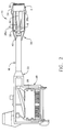
- FIG. 2 is a schematic diagram showing the structure of an ultrasonic probe in accordance with a first preferred embodiment of the invention wherein the transducer pallet is thermally coupled to the cable via a soldered internal heat pipe.
- FIG. 3 is a schematic diagram showing on a magnified scale the handle of the ultrasonic probe shown in FIG. 2.
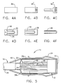
- FIGS. 4A through 4F are schematic diagrams showing six variations of the internal heat pipe configuration in accordance with the preferred embodiments of the invention.
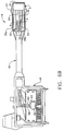
- FIG. 5 is a schematic diagram showing the probe handle of an ultrasonic probe in accordance with a second preferred embodiment of the invention wherein the transducer pallet is thermally coupled to the cable via a passive fluid coupling.
- FIGS. 6A and 6B are schematic diagrams showing the probe handle and system connector, respectively, of an ultrasonic probe in accordance with a third preferred embodiment of the invention wherein the transducer pallet is thermally coupled to the cable via an active fluid coupling.
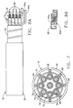
- FIG. 7 is a schematic sectional view showing the cable of an ultrasonic probe in accordance with a fourth preferred embodiment of the invention wherein heat pipes are embedded in a cable shield.
- FIG. 8A is a schematic diagram showing the armored cable of an ultrasonic probe in accordance with a fifth preferred embodiment of the invention wherein heat pipes are molded into the cable armor.
- FIG. 8B is a sectional view of the armor incorporated in the probe shown in FIG. 8A.
- FIG. 9 is a schematic diagram showing the probe handle of an ultrasonic probe in accordance with a sixth preferred embodiment of the invention wherein the transducer pallet is thermally coupled to the cable via a semiconductor chiller.
- Referring to FIG. 2, an ultrasound probe in accordance with the preferred embodiment of the invention comprises a
probe handle 14 connected to one end of acable 16 and asystem connector 18 connected to the other end of the cable. Means 20 and 22 for relieving stress are provided at the cable/housing and system connector/cable connections, respectively. The probe handle 14 comprises aplastic shell 24 which houses aconventional transducer pallet 2. The system connector comprises aplastic housing 26 in which aPCB 28 is mounted. The signal electrodes of the transducer array are electrically connected toPCB 28 viaflexible PCB 6,signal wiring 30 and a multiplicity of coaxial cables incable 16. - As shown on a magnified scale in FIG. 3, the probe handle 14 in accordance with a first preferred embodiment of the invention comprises a
transducer pallet 2 mounted inplastic shell 24. The pallet is arranged so that the front face of the transducer array is acoustically coupled to acylindrical focusing lens 32 which contacts the patient. Thetransducer pallet 2 and focusinglens 32 are mounted insideplastic shell 24 by adhesively bonding the perimeter oflens 32 in an opening of corresponding shape formed in one end ofshell 24. The other end ofshell 24 is attached to thecable jacket 34. In accordance with the first preferred embodiment, at least oneinternal heat pipe 36, made of a material having a relatively high coefficient of thermal conductivity, is thermally coupled to a central portion of the transducer pallet. In addition,external heat pipes - The signal electrodes of the transducer array are electrically connected to the central conductors (not shown in FIG. 3) of respective coaxial cables via conductive traces formed on
flexible PCB 6 and viasignal wiring 30. In this embodiment, the cable overall (braided)shield 40 is brought into the probe handle 14 through the cable strain relief and directly soldered to theheat pipe structure 36 that is connected topallet 2. The solder bead is indicated by numeral 42 in FIG. 3. This provides the most direct and effective method of piping heat from the source into the extended heat sink formed by the cable. Likewise theexternal heat pipes overall shield 40. The cable comprises a bundle of coaxial cables surrounded by the overall shield. In addition to (or as an alternative to) thermally coupling the internal heat pipe to the overall shield, the internal heat pipe can be thermally coupled to the shield braid of each coaxial cable in the bundle. - The
internal heat pipe 36 may comprise a flexible sheet or stiff plate of heat conductive material having one of the configurations depicted in FIGS. 4A, 4B and 4C. The configurations depicted in FIGS. 4B and 4C comprise respectiveflat heat pipes 36' and 36", each having a comb-like structure which is thermally coupled to the transducer pallet by embedding the comb fingers in the backing material. - In accordance with a second preferred embodiment shown in FIG. 5, the
transducer pallet 2 is thermally coupled to thecable shield braid 40 via a passive fluid coupling comprising acable fluid path 44 incorporated in the cable bundle, afluid channel 46 mounted on and thermally coupled to theinternal heat pipe 36, and a coupling joint 48 for connectingcable fluid path 44 tofluid channel 46. Thefluid channel 46 may take the form of a U-shaped pipe as seen in FIG. 4D, while the cable fluid path is a pipe incorporated in the cable bundle and thermally coupled to the cable shield braid. In the latter case, the coupling joint 48 takes the form of a straight pipe in fluid communication with the ends of the legs of the U-shaped fluid channel and with an end of thecable fluid path 44, as seen in FIG. 4D. Eachpipe - In accordance with a third preferred embodiment shown in FIGS. 6A and 6B, the
transducer pallet 2 is thermally coupled to thecable shield braid 40 via an active fluid coupling comprising an inputcable fluid path 50 and a returncable fluid path 52 both incorporated in the cable bundle, afluid channel 54 mounted on and thermally coupled to theinternal heat pipe 36, andcoupling joints fluid channel 54. Like thefluid channel 46 incorporated in the embodiment of FIG. 5, thefluid channel 54 may take the form of a U-shaped pipe as seen in FIG. 4E, while the input and return cable fluid paths are respective pipes incorporated in the cable bundle and thermally coupled to the cable shield braid. One end of the inputcable fluid path 50 is in fluid communication with an input leg offluid channel 54; the end of the returncable fluid path 52 is in fluid communication with an output leg offluid channel 54. The input and out-put legs offluid channel 54 may be mounted on the same side (as shown in FIG. 4E) or on opposite sides of the internal heat pipe 36 (as shown in FIG. 6A). In the latter case, part of the U-shaped fluid channel is embedded in the backing material. Eachpipe - The third preferred embodiment utilizes active movement, i.e., recirculating flow, of the cooling fluid in cooling pipes to cool the probe handle. This might be accomplished with a small micromotor 60 (see FIG. 6B) powered by the system. The micromotor 60 drives a pump 62 which pumps cooling fluid from a cooling
fluid input line 64 to a coolingfluid output line 66 arranged inside thesystem connector 18. The coolingfluid input line 64 is in flow communication with the returncable fluid path 52 and the coolingfluid output line 66 is in flow communication with the inputcable fluid path 50. Thus, pump 62, coolingfluid output line 66, inputcable fluid path 50,fluid channel 54, returncable fluid path 52 and coolingfluid input line 64 form a closed circuit for recirculating flow of cooling fluid. As an alternative to the use of a motor to drive recirculation of the cooling fluid, recirculating flow may be driven by active cooling of a portion of the fluid circuit, thereby generating a thermal gradient which draws heat out of the probe handle. In either case, energy is expended in order to create cooling in the transducer handle. - A variation on the active fluid coupling embodiment is to eliminate the internal heat pipe and simply embed the curved part of the U-shaped fluid channel 46 (see FIG. 4F) in the backing material.
- In accordance with a fourth preferred embodiment shown in FIG. 7, a plurality of
heat pipes 68 are implanted in the overall braid or shield 40 of the cable assembly. Theoverall shield 40 is in the shape of a braided annulus bounded by thecable jacket 34 on an outer periphery and by aninternal sheath 70 on an inner periphery. Theinternal sheath 70 surrounds a bundle ofcoaxial cables 72. Each coaxial cable in turn comprises ajacket 74, braided shielding 76,dielectric 78 and acenter conductor 80 arranged in well-known manner. The cableshield heat pipes 68 may be circumferentially distributed at equal angular intervals around theoverall shield 40. The heat pipes may be made of any suitable material having a high coefficient of thermal conductivity, including gold threads woven into the overall braid (selected heat pipes with high coefficients of thermal conductivity) or a tube filled with fluid. - In the case of armored cable of the type shown in FIG. 8A, the bundle of coaxial cables is surrounded by a
spiral armor 82. The armor cross section can be molded to provide one or more channels, which are filled with heat conductive material for transporting heat along the cable and away from the probe handle. Alternatively, as best seen in FIG. 8B, the armor can be molded to provide input and returnchannels - Finally, in accordance with a sixth preferred embodiment shown in FIG. 9, a
semiconductor chiller 86 is mounted in heat conductive relationship with thetransducer pallet 2. Then an arrangement similar to that shown in FIGS. 6A and 6B is used to pipe the heat generated by thesemiconductor chiller 86 to the outside environment. In this case, however, theinternal heat pipe 36 is placed in heat conductive relationship with thesemiconductor chiller 86, instead of being thermally coupled to the transducer pallet directly.
Claims (10)
- An ultrasonic probe comprising a probe handle (14) and a cable (16) connected thereto, said cable comprising a heat conductive structure (44, 68, 76 or 84) extending along a length of said cable, and said probe handle comprising a transducer pallet (2) and a heat pipe (36), characterized in that said heat pipe is in contact with a portion of said transducer pallet and thermally coupled to said heat conductive structure in said cable.
- The ultrasonic probe as defined in claim 1, characterized in that said heat conductive structure comprises threads (68) of heat conductive material.
- The ultrasonic probe as defined in claim 1, characterized in that said heat conductive structure comprises a tube (44).
- The ultrasonic probe as defined in claim 1, characterized in that said cable comprises a braided overall shield (76), and said heat conductive structure is implanted in said braided overall shield.
- The ultrasonic probe as defined in claim 1, characterized in that said heat conductive structure comprises a braided overall shield (76) of said cable.
- The ultrasonic probe as defined in claim 1, characterized in that said probe handle further comprises a first tube (46) attached to said heat pipe.
- The ultrasonic probe as defined in claim 6, characterized in that said heat conductive structure comprises a second tube (44) in flow communication with said first tube.
- The ultrasonic probe as defined in claim 6, characterized in that said first tube has an inlet and an outlet, and said heat conductive structure comprises a second tube (50) in flow communication with said inlet of said first tube and a third tube (52) in flow communication with said outlet of said first tube.
- The ultrasonic probe as defined in claim 8, further characterized by a pump (60) and a motor (62), wherein said second tube is in flow communication with said third tube via said pump.
- The ultrasonic probe as defined in claim 8, further characterized by a semiconductor chiller (86) arranged to extract heat from said transducer pallet and transfer extracted heat to said heat pipe.
Applications Claiming Priority (2)
| Application Number | Priority Date | Filing Date | Title |
|---|---|---|---|
| US580564 | 1984-02-15 | ||
| US08/580,564 US5721463A (en) | 1995-12-29 | 1995-12-29 | Method and apparatus for transferring heat from transducer array of ultrasonic probe |
Publications (3)
| Publication Number | Publication Date |
|---|---|
| EP0782125A2 true EP0782125A2 (en) | 1997-07-02 |
| EP0782125A3 EP0782125A3 (en) | 1999-02-03 |
| EP0782125B1 EP0782125B1 (en) | 2003-07-02 |
Family
ID=24321608
Family Applications (1)
| Application Number | Title | Priority Date | Filing Date |
|---|---|---|---|
| EP96309274A Expired - Lifetime EP0782125B1 (en) | 1995-12-29 | 1996-12-19 | Method and apparatus for transferring heat from transducer array of ultrasonic probe |
Country Status (4)
| Country | Link |
|---|---|
| US (1) | US5721463A (en) |
| EP (1) | EP0782125B1 (en) |
| JP (1) | JPH09294744A (en) |
| DE (1) | DE69628901T2 (en) |
Cited By (18)
| Publication number | Priority date | Publication date | Assignee | Title |
|---|---|---|---|---|
| WO2000008630A1 (en) * | 1998-08-04 | 2000-02-17 | Dr. Hielscher Gmgh | Heat dissipating device, especially for high performance ultrasonic transducers |
| EP1032250A3 (en) * | 1999-02-25 | 2001-04-04 | International Business Machines Corporation | Cable and heat sink |
| DE10254894B3 (en) * | 2002-11-20 | 2004-05-27 | Dr. Hielscher Gmbh | Cooling device for ultrasonic transducers has cooling fluid passed through flow channels at defined pressure for reducing or preventing cavitation |
| WO2005030055A1 (en) | 2003-09-30 | 2005-04-07 | Matsushita Electric Industrial Co., Ltd. | Ultrasonic probe |
| DE10350021B3 (en) * | 2003-10-27 | 2005-05-25 | Sick Engineering Gmbh | Ultrasonic probe, e.g. for measuring flowing media, has coolant feed channel enclosing transducer and fed out to inside of sound surface; cooling fluid flows round transducer, is diverted into outflow channel immediately after sound surface |
| EP1534140A1 (en) * | 2002-07-17 | 2005-06-01 | Vermon | Ultrasound array transducer for catheter use |
| EP1652476A2 (en) * | 2004-10-27 | 2006-05-03 | Kabushiki Kaisha Toshiba | Ultrasonic probe and ultrasonic diagnostic apparatus |
| WO2006114736A3 (en) * | 2005-04-25 | 2007-02-15 | Koninkl Philips Electronics Nv | Ultrasound transducer assembly having improved thermal management |
| US7417187B2 (en) | 2006-01-13 | 2008-08-26 | Sumitomo Electric Industries, Ltd. | Composite cable and composite cable processed product |
| EP2095844A1 (en) * | 2002-01-15 | 2009-09-02 | Ultrazonix DNT AB | Device for mini-invasive ultrasound treatment of an object by a heat-isolated transducer |
| WO2010011034A1 (en) | 2008-07-22 | 2010-01-28 | Humanscan Co., Ltd. | Ultrasonic probe having heat sink |
| WO2013140298A3 (en) * | 2012-03-20 | 2014-01-23 | Koninklijke Philips N.V. | Ultrasonic matrix array probe with thermally dissipating cable |
| WO2013140283A3 (en) * | 2012-03-20 | 2014-03-13 | Koninklijke Philips N.V. | Ultrasonic matrix array probe with thermally dissipating cable and backing block heat exchange |
| WO2014080312A1 (en) * | 2012-11-20 | 2014-05-30 | Koninklijke Philips N.V. | Frameless ultrasound probes with heat dissipation |
| CN109414253A (en) * | 2016-06-30 | 2019-03-01 | 富士胶片株式会社 | Ultrasonic endoscope |
| JPWO2018003232A1 (en) * | 2016-06-30 | 2019-04-11 | 富士フイルム株式会社 | Ultrasound endoscope and manufacturing method thereof |
| EP3479772A4 (en) * | 2016-06-30 | 2019-05-22 | FUJIFILM Corporation | Ultrasonic endoscope |
| US11864951B2 (en) | 2018-11-16 | 2024-01-09 | Supersonic Imagine | Probe having a cooling chamber and method for manufacturing such a probe |
Families Citing this family (57)
| Publication number | Priority date | Publication date | Assignee | Title |
|---|---|---|---|---|
| US6039059A (en) * | 1996-09-30 | 2000-03-21 | Verteq, Inc. | Wafer cleaning system |
| US6142947A (en) * | 1998-12-04 | 2000-11-07 | General Electric Company | Ultrasound probe and related methods of assembly/disassembly |
| US6300706B1 (en) * | 1999-07-14 | 2001-10-09 | The United States Of America As Represented By The Secretary Of The Army | Compound semiconductor monolithic frequency sources and actuators |
| US6610011B2 (en) | 2000-12-27 | 2003-08-26 | Siemens Medical Solutions Usa, Inc. | Method and system for control of probe heating using lens reflection pulse-echo feedback |
| DE10164758B4 (en) * | 2001-05-25 | 2006-12-07 | Siemens Ag | A method for operating a hand-held applicator of an ultrasonic diagnostic device and ultrasonic diagnostic device with an operated according to this method applicator |
| JP4782320B2 (en) * | 2001-07-31 | 2011-09-28 | 日立アロカメディカル株式会社 | Ultrasonic diagnostic equipment |
| US7314447B2 (en) * | 2002-06-27 | 2008-01-01 | Siemens Medical Solutions Usa, Inc. | System and method for actively cooling transducer assembly electronics |
| US7052463B2 (en) * | 2002-09-25 | 2006-05-30 | Koninklijke Philips Electronics, N.V. | Method and apparatus for cooling a contacting surface of an ultrasound probe |
| US6709392B1 (en) | 2002-10-10 | 2004-03-23 | Koninklijke Philips Electronics N.V. | Imaging ultrasound transducer temperature control system and method using feedback |
| US6669638B1 (en) | 2002-10-10 | 2003-12-30 | Koninklijke Philips Electronics N.V. | Imaging ultrasound transducer temperature control system and method |
| US6663578B1 (en) | 2002-10-11 | 2003-12-16 | Koninklijke Philips Electronics N.V. | Operator supervised temperature control system and method for an ultrasound transducer |
| US7409564B2 (en) * | 2004-03-22 | 2008-08-05 | Kump Ken S | Digital radiography detector with thermal and power management |
| US20050215892A1 (en) * | 2004-03-22 | 2005-09-29 | Siemens Medical Solutions Usa, Inc. | System and method for transducer array cooling through forced convection |
| US7367945B2 (en) * | 2004-03-29 | 2008-05-06 | General Electric Company | Ultrasound system |
| JP4602013B2 (en) * | 2004-07-13 | 2010-12-22 | 株式会社東芝 | Ultrasonic probe |
| US7105986B2 (en) * | 2004-08-27 | 2006-09-12 | General Electric Company | Ultrasound transducer with enhanced thermal conductivity |
| JP4594710B2 (en) * | 2004-12-02 | 2010-12-08 | 株式会社東芝 | Ultrasonic probe and ultrasonic diagnostic apparatus |
| JP4685408B2 (en) * | 2004-10-27 | 2011-05-18 | 株式会社東芝 | Ultrasonic probe |
| US20060173344A1 (en) * | 2005-01-19 | 2006-08-03 | Siemens Medical Solutions Usa, Inc. | Method for using a refrigeration system to remove waste heat from an ultrasound transducer |
| JP4624165B2 (en) * | 2005-04-13 | 2011-02-02 | ジーイー・メディカル・システムズ・グローバル・テクノロジー・カンパニー・エルエルシー | Ultrasonic probe and ultrasonic diagnostic apparatus |
| WO2007000680A2 (en) * | 2005-06-29 | 2007-01-04 | Koninklijke Philips Electronics, N.V. | Optimized temperature measurement in an ultrasound transducer |
| US9955947B2 (en) * | 2005-07-15 | 2018-05-01 | General Electric Company | Device and method for shielding an ultrasound probe |
| US20070167821A1 (en) | 2005-11-30 | 2007-07-19 | Warren Lee | Rotatable transducer array for volumetric ultrasound |
| US20070167826A1 (en) * | 2005-11-30 | 2007-07-19 | Warren Lee | Apparatuses for thermal management of actuated probes, such as catheter distal ends |
| JP4843395B2 (en) * | 2006-07-10 | 2011-12-21 | 日本電波工業株式会社 | Ultrasonic probe |
| US20080125658A1 (en) * | 2006-09-01 | 2008-05-29 | General Electric Company | Low-profile acoustic transducer assembly |
| US8475375B2 (en) * | 2006-12-15 | 2013-07-02 | General Electric Company | System and method for actively cooling an ultrasound probe |
| DE502008000385D1 (en) * | 2007-03-06 | 2010-04-08 | Ebm Papst St Georgen Gmbh & Co | Electronically commutated external rotor motor with a printed circuit board |
| US20080228249A1 (en) * | 2007-03-12 | 2008-09-18 | Barnitz James C | Medical device with thermal management of the device-tissue interface |
| JP5154144B2 (en) | 2007-05-31 | 2013-02-27 | 富士フイルム株式会社 | Ultrasound endoscope and ultrasound endoscope apparatus |
| JP5154146B2 (en) * | 2007-06-05 | 2013-02-27 | 富士フイルム株式会社 | Ultrasound endoscope and ultrasound endoscope apparatus |
| JP5171191B2 (en) * | 2007-09-28 | 2013-03-27 | 富士フイルム株式会社 | Ultrasonic probe |
| US7918799B2 (en) * | 2008-02-18 | 2011-04-05 | General Electric Company | Method and interface for cooling electronics that generate heat |
| US20100191113A1 (en) * | 2009-01-28 | 2010-07-29 | General Electric Company | Systems and methods for ultrasound imaging with reduced thermal dose |
| JP2010259695A (en) * | 2009-05-11 | 2010-11-18 | Toshiba Corp | Ultrasonic probe |
| JP5619380B2 (en) * | 2009-06-24 | 2014-11-05 | 株式会社東芝 | Ultrasonic probe |
| DE102009049683B4 (en) * | 2009-10-19 | 2016-06-09 | Richard Wolf Gmbh | Endoscopic instrument |
| JP2011181731A (en) * | 2010-03-02 | 2011-09-15 | Molex Inc | Electronic apparatus with socket for card type component |
| US9186123B1 (en) | 2010-08-24 | 2015-11-17 | Fujifilm Sonosite, Inc. | Ultrasound scanners with anisotropic heat distributors for ultrasound probe |
| JP2014516686A (en) * | 2011-05-17 | 2014-07-17 | コーニンクレッカ フィリップス エヌ ヴェ | Matrix ultrasound probe using passive heat dissipation |
| JP2011229976A (en) * | 2011-08-08 | 2011-11-17 | Toshiba Corp | Ultrasonic probe and ultrasonic imaging apparatus |
| US9072487B2 (en) | 2012-05-11 | 2015-07-07 | General Electric Company | Ultrasound probe thermal drain |
| KR20140144466A (en) * | 2013-06-11 | 2014-12-19 | 삼성전자주식회사 | Portable Ultrasonic Probe |
| EP2992829B1 (en) | 2014-09-02 | 2018-06-20 | Esaote S.p.A. | Ultrasound probe with optimized thermal management |
| WO2016035362A1 (en) * | 2014-09-02 | 2016-03-10 | オリンパス株式会社 | Ultrasonic endoscope |
| US20170238902A1 (en) * | 2016-02-19 | 2017-08-24 | General Electric Company | System for reducing a footprint of an ultrasound transducer probe |
| WO2018016128A1 (en) * | 2016-07-19 | 2018-01-25 | オリンパス株式会社 | Ultrasonic probe |
| US10779801B2 (en) | 2016-09-21 | 2020-09-22 | Clarius Mobile Health Corp. | Ultrasound apparatus with improved heat dissipation and methods for providing same |
| CN111491577B (en) * | 2017-11-10 | 2023-12-01 | 巴德股份有限公司 | Radiator for conduit and system and method thereof |
| JP7339388B2 (en) * | 2017-11-10 | 2023-09-05 | シー・アール・バード・インコーポレーテッド | Catheter heat sink and system and method |
| US11717271B2 (en) | 2018-03-30 | 2023-08-08 | Koninklijke Philips N.V. | Thermally-conductive material layer and internal structure for ultrasound imaging |
| EP3808277B1 (en) * | 2018-06-12 | 2023-09-27 | Edan Instruments, Inc | Ultrasound transducer, ultrasonic probe, and ultrasonic detection apparatus |
| US20200178941A1 (en) * | 2018-12-07 | 2020-06-11 | General Electric Company | Ultrasound probe and method of making the same |
| US11497468B2 (en) | 2018-12-21 | 2022-11-15 | Fujifilm Sonosite, Inc. | Ultrasound probe |
| CN114555247B (en) | 2019-10-10 | 2023-09-01 | 新宁研究院 | System and method for cooling ultrasound transducers and ultrasound transducer arrays |
| EP3811872B1 (en) | 2019-10-23 | 2023-07-26 | Esaote S.p.A. | Ultrasound probe with improved thermal management |
| KR102406068B1 (en) * | 2020-01-31 | 2022-06-08 | 주식회사 세라젬 | Multi functional probe capable of electromagnetic wave shielding |
Family Cites Families (12)
| Publication number | Priority date | Publication date | Assignee | Title |
|---|---|---|---|---|
| US2789557A (en) * | 1952-01-07 | 1957-04-23 | Raytheon Mfg Co | Ultrasonic therapeutic devices |
| CH442797A (en) * | 1965-06-22 | 1967-08-31 | List Hans Dipl Ing Dr Dr H C P | Piezoelectric pressure transducer and process for its manufacture |
| US3518766A (en) * | 1969-01-30 | 1970-07-07 | Emanuel Burt | Piezoelectric cleaning device with removable workpiece |
| JPH0653120B2 (en) * | 1985-05-10 | 1994-07-20 | オリンパス光学工業株式会社 | Ultrasonic diagnostic equipment |
| US5225734A (en) * | 1990-03-01 | 1993-07-06 | Canon Kabushiki Kaisha | Vibration wave driven motor |
| US5213103A (en) * | 1992-01-31 | 1993-05-25 | Acoustic Imaging Technologies Corp. | Apparatus for and method of cooling ultrasonic medical transducers by conductive heat transfer |
| DE4325028B4 (en) * | 1993-07-26 | 2005-05-19 | Siemens Ag | Ultrasonic transducer device comprising a one or two dimensional array of transducer elements |
| US5584183A (en) * | 1994-02-18 | 1996-12-17 | Solid State Cooling Systems | Thermoelectric heat exchanger |
| US5560362A (en) * | 1994-06-13 | 1996-10-01 | Acuson Corporation | Active thermal control of ultrasound transducers |
| US5598051A (en) * | 1994-11-21 | 1997-01-28 | General Electric Company | Bilayer ultrasonic transducer having reduced total electrical impedance |
| US5545942A (en) * | 1994-11-21 | 1996-08-13 | General Electric Company | Method and apparatus for dissipating heat from a transducer element array of an ultrasound probe |
| US5541468A (en) * | 1994-11-21 | 1996-07-30 | General Electric Company | Monolithic transducer array case and method for its manufacture |
-
1995
- 1995-12-29 US US08/580,564 patent/US5721463A/en not_active Expired - Fee Related
-
1996
- 1996-12-19 DE DE69628901T patent/DE69628901T2/en not_active Expired - Fee Related
- 1996-12-19 EP EP96309274A patent/EP0782125B1/en not_active Expired - Lifetime
-
1997
- 1997-01-06 JP JP9000203A patent/JPH09294744A/en not_active Withdrawn
Non-Patent Citations (1)
| Title |
|---|
| None |
Cited By (44)
| Publication number | Priority date | Publication date | Assignee | Title |
|---|---|---|---|---|
| US6481493B1 (en) | 1998-08-04 | 2002-11-19 | Dr. Heilscher Gmbh | Arrangement for heat discharge, particularly for ultrasonic transducers with high performance |
| WO2000008630A1 (en) * | 1998-08-04 | 2000-02-17 | Dr. Hielscher Gmgh | Heat dissipating device, especially for high performance ultrasonic transducers |
| EP1032250A3 (en) * | 1999-02-25 | 2001-04-04 | International Business Machines Corporation | Cable and heat sink |
| US6452093B1 (en) | 1999-02-25 | 2002-09-17 | International Business Machines Corporation | Cable and heat sink |
| EP2095844A1 (en) * | 2002-01-15 | 2009-09-02 | Ultrazonix DNT AB | Device for mini-invasive ultrasound treatment of an object by a heat-isolated transducer |
| EP1534140A1 (en) * | 2002-07-17 | 2005-06-01 | Vermon | Ultrasound array transducer for catheter use |
| EP1534140A4 (en) * | 2002-07-17 | 2009-04-29 | Vermon | Ultrasound array transducer for catheter use |
| US8004158B2 (en) | 2002-11-20 | 2011-08-23 | Dr. Hielscher Gmbh | Method and device for cooling ultrasonic transducers |
| DE10254894B3 (en) * | 2002-11-20 | 2004-05-27 | Dr. Hielscher Gmbh | Cooling device for ultrasonic transducers has cooling fluid passed through flow channels at defined pressure for reducing or preventing cavitation |
| EP1671588A1 (en) * | 2003-09-30 | 2006-06-21 | Matsushita Electric Industrial Co., Ltd. | Ultrasonic probe |
| EP1671588A4 (en) * | 2003-09-30 | 2013-08-07 | Panasonic Corp | Ultrasonic probe |
| WO2005030055A1 (en) | 2003-09-30 | 2005-04-07 | Matsushita Electric Industrial Co., Ltd. | Ultrasonic probe |
| DE10350021B3 (en) * | 2003-10-27 | 2005-05-25 | Sick Engineering Gmbh | Ultrasonic probe, e.g. for measuring flowing media, has coolant feed channel enclosing transducer and fed out to inside of sound surface; cooling fluid flows round transducer, is diverted into outflow channel immediately after sound surface |
| EP1652476A3 (en) * | 2004-10-27 | 2006-06-07 | Kabushiki Kaisha Toshiba | Ultrasonic probe and ultrasonic diagnostic apparatus |
| EP1792571A1 (en) * | 2004-10-27 | 2007-06-06 | Kabushiki Kaisha Toshiba | Ultrasonic probe and ultrasonic diagnostic apparatus |
| EP1806097A1 (en) * | 2004-10-27 | 2007-07-11 | Kabushiki Kaisha Toshiba | Ultrasonic probe and ultrasonic apparatus |
| EP1652476A2 (en) * | 2004-10-27 | 2006-05-03 | Kabushiki Kaisha Toshiba | Ultrasonic probe and ultrasonic diagnostic apparatus |
| US8333702B2 (en) | 2004-10-27 | 2012-12-18 | Kabushiki Kaisha Toshiba | Ultrasonic probe and ultrasonic diagnostic apparatus |
| WO2006114736A3 (en) * | 2005-04-25 | 2007-02-15 | Koninkl Philips Electronics Nv | Ultrasound transducer assembly having improved thermal management |
| US7417187B2 (en) | 2006-01-13 | 2008-08-26 | Sumitomo Electric Industries, Ltd. | Composite cable and composite cable processed product |
| AT503999B1 (en) * | 2006-01-13 | 2008-10-15 | Sumitomo Electric Industries | MIXED CABLE AND PRODUCT WITH ONE SUCH CABLE |
| EP2309930A4 (en) * | 2008-07-22 | 2011-10-05 | Humanscan Co Ltd | Ultrasonic probe having heat sink |
| EP2309930A1 (en) * | 2008-07-22 | 2011-04-20 | Humanscan Co., Ltd. | Ultrasonic probe having heat sink |
| WO2010011034A1 (en) | 2008-07-22 | 2010-01-28 | Humanscan Co., Ltd. | Ultrasonic probe having heat sink |
| CN102098965A (en) * | 2008-07-22 | 2011-06-15 | 人体扫描有限公司 | Ultrasonic probe having heat sink |
| CN104205207B (en) * | 2012-03-20 | 2020-11-03 | 皇家飞利浦有限公司 | Ultrasonic matrix array probe with heat dissipating cable |
| WO2013140298A3 (en) * | 2012-03-20 | 2014-01-23 | Koninklijke Philips N.V. | Ultrasonic matrix array probe with thermally dissipating cable |
| WO2013140283A3 (en) * | 2012-03-20 | 2014-03-13 | Koninklijke Philips N.V. | Ultrasonic matrix array probe with thermally dissipating cable and backing block heat exchange |
| CN104205207A (en) * | 2012-03-20 | 2014-12-10 | 皇家飞利浦有限公司 | Ultrasonic matrix array probe with thermally dissipating cable |
| RU2620867C2 (en) * | 2012-03-20 | 2017-05-30 | Конинклейке Филипс Н.В. | Ultrasound matrix probe with heat-dissipating cable and heat transfer through base unit |
| CN104205206B (en) * | 2012-03-20 | 2017-10-20 | 皇家飞利浦有限公司 | Ultrasonic matrix array probe with radiating cable and pad heat exchanger |
| US9867592B2 (en) | 2012-03-20 | 2018-01-16 | Koninklijke Philips N.V. | Ultrasonic matrix array probe with thermally dissipating cable |
| US9872669B2 (en) | 2012-03-20 | 2018-01-23 | Koninklijke Philips N.V. | Ultrasonic matrix array probe with thermally dissipating cable and backing block heat exchange |
| US10178986B2 (en) | 2012-03-20 | 2019-01-15 | Koninklijke Philips N.V. | Ultrasonic matrix array probe with thermally dissipating cable and backing block heat exchange |
| WO2014080312A1 (en) * | 2012-11-20 | 2014-05-30 | Koninklijke Philips N.V. | Frameless ultrasound probes with heat dissipation |
| JPWO2018003232A1 (en) * | 2016-06-30 | 2019-04-11 | 富士フイルム株式会社 | Ultrasound endoscope and manufacturing method thereof |
| EP3479771A4 (en) * | 2016-06-30 | 2019-05-22 | FUJIFILM Corporation | Ultrasonic endoscope |
| EP3479772A4 (en) * | 2016-06-30 | 2019-05-22 | FUJIFILM Corporation | Ultrasonic endoscope |
| EP3479769A4 (en) * | 2016-06-30 | 2019-08-21 | FUJIFILM Corporation | Ultrasonic endoscope and method for manufacturing same |
| CN109414253A (en) * | 2016-06-30 | 2019-03-01 | 富士胶片株式会社 | Ultrasonic endoscope |
| US11076828B2 (en) | 2016-06-30 | 2021-08-03 | Fujifilm Corporation | Ultrasonic endoscope |
| US11076838B2 (en) | 2016-06-30 | 2021-08-03 | Fujifilm Corporation | Ultrasonic endoscope |
| US11317897B2 (en) | 2016-06-30 | 2022-05-03 | Fujifilm Corporation | Ultrasonic endoscope and method for manufacturing same |
| US11864951B2 (en) | 2018-11-16 | 2024-01-09 | Supersonic Imagine | Probe having a cooling chamber and method for manufacturing such a probe |
Also Published As
| Publication number | Publication date |
|---|---|
| EP0782125B1 (en) | 2003-07-02 |
| DE69628901T2 (en) | 2004-04-22 |
| DE69628901D1 (en) | 2003-08-07 |
| JPH09294744A (en) | 1997-11-18 |
| EP0782125A3 (en) | 1999-02-03 |
| US5721463A (en) | 1998-02-24 |
Similar Documents
| Publication | Publication Date | Title |
|---|---|---|
| EP0782125B1 (en) | Method and apparatus for transferring heat from transducer array of ultrasonic probe | |
| US5545942A (en) | Method and apparatus for dissipating heat from a transducer element array of an ultrasound probe | |
| US7314447B2 (en) | System and method for actively cooling transducer assembly electronics | |
| US5577507A (en) | Compound lens for ultrasound transducer probe | |
| US8551003B2 (en) | Ultrasonic probe and ultrasonic diagnosis device | |
| US6936008B2 (en) | Ultrasound system with cableless coupling assembly | |
| US3964014A (en) | Sonic transducer array | |
| EP2610860B1 (en) | Ultrasound probe and manufacturing method thereof | |
| JP5031450B2 (en) | Composite piezoelectric material, ultrasonic probe, ultrasonic endoscope, and ultrasonic diagnostic apparatus | |
| US5598051A (en) | Bilayer ultrasonic transducer having reduced total electrical impedance | |
| US20040002655A1 (en) | System and method for improved transducer thermal design using thermo-electric cooling | |
| JP2014516686A (en) | Matrix ultrasound probe using passive heat dissipation | |
| US20060116584A1 (en) | Miniaturized ultrasonic transducer | |
| CN101444430A (en) | Backing material, ultrasonic probe, ultrasonic endoscope, ultrasonic diagnostic device, and ultrasonic endoscope device | |
| US4977329A (en) | Arrangement for shielding electronic components and providing power thereto | |
| US6142947A (en) | Ultrasound probe and related methods of assembly/disassembly | |
| AU2017373887A1 (en) | High intensity focused ultrasound (HIFU) device and system | |
| JP6571870B2 (en) | Ultrasound endoscope | |
| US20200093463A1 (en) | Acoustic damping for ultrasound imaging devices | |
| CN114555247A (en) | System and method for cooling ultrasound transducers and ultrasound transducer arrays | |
| JPH1094540A (en) | Ultrasonic probe | |
| CN104768472A (en) | Ultrasonic probe | |
| WO2018003311A1 (en) | Ultrasonic endoscope | |
| JP4376533B2 (en) | Ultrasonic probe | |
| WO2018003310A1 (en) | Ultrasonic endoscope |
Legal Events
| Date | Code | Title | Description |
|---|---|---|---|
| PUAI | Public reference made under article 153(3) epc to a published international application that has entered the european phase |
Free format text: ORIGINAL CODE: 0009012 |
|
| AK | Designated contracting states |
Kind code of ref document: A2 Designated state(s): DE FR IT |
|
| PUAL | Search report despatched |
Free format text: ORIGINAL CODE: 0009013 |
|
| AK | Designated contracting states |
Kind code of ref document: A3 Designated state(s): DE FR IT |
|
| 17P | Request for examination filed |
Effective date: 19990803 |
|
| 17Q | First examination report despatched |
Effective date: 20010601 |
|
| GRAG | Despatch of communication of intention to grant |
Free format text: ORIGINAL CODE: EPIDOS AGRA |
|
| GRAG | Despatch of communication of intention to grant |
Free format text: ORIGINAL CODE: EPIDOS AGRA |
|
| GRAH | Despatch of communication of intention to grant a patent |
Free format text: ORIGINAL CODE: EPIDOS IGRA |
|
| GRAG | Despatch of communication of intention to grant |
Free format text: ORIGINAL CODE: EPIDOS AGRA |
|
| GRAH | Despatch of communication of intention to grant a patent |
Free format text: ORIGINAL CODE: EPIDOS IGRA |
|
| GRAH | Despatch of communication of intention to grant a patent |
Free format text: ORIGINAL CODE: EPIDOS IGRA |
|
| GRAH | Despatch of communication of intention to grant a patent |
Free format text: ORIGINAL CODE: EPIDOS IGRA |
|
| GRAA | (expected) grant |
Free format text: ORIGINAL CODE: 0009210 |
|
| AK | Designated contracting states |
Designated state(s): DE FR IT |
|
| REF | Corresponds to: |
Ref document number: 69628901 Country of ref document: DE Date of ref document: 20030807 Kind code of ref document: P |
|
| ET | Fr: translation filed | ||
| PLBE | No opposition filed within time limit |
Free format text: ORIGINAL CODE: 0009261 |
|
| STAA | Information on the status of an ep patent application or granted ep patent |
Free format text: STATUS: NO OPPOSITION FILED WITHIN TIME LIMIT |
|
| 26N | No opposition filed |
Effective date: 20040405 |
|
| PGFP | Annual fee paid to national office [announced via postgrant information from national office to epo] |
Ref country code: FR Payment date: 20041217 Year of fee payment: 9 |
|
| PGFP | Annual fee paid to national office [announced via postgrant information from national office to epo] |
Ref country code: DE Payment date: 20050131 Year of fee payment: 9 |
|
| PG25 | Lapsed in a contracting state [announced via postgrant information from national office to epo] |
Ref country code: IT Free format text: LAPSE BECAUSE OF NON-PAYMENT OF DUE FEES Effective date: 20051219 |
|
| PG25 | Lapsed in a contracting state [announced via postgrant information from national office to epo] |
Ref country code: DE Free format text: LAPSE BECAUSE OF NON-PAYMENT OF DUE FEES Effective date: 20060701 |
|
| PG25 | Lapsed in a contracting state [announced via postgrant information from national office to epo] |
Ref country code: FR Free format text: LAPSE BECAUSE OF NON-PAYMENT OF DUE FEES Effective date: 20060831 |
|
| REG | Reference to a national code |
Ref country code: FR Ref legal event code: ST Effective date: 20060831 |