EP0782010B1 - Antenne linéaire électroacoustique d'émission et antenne d'émission/réception comprenant une telle antenne - Google Patents
Antenne linéaire électroacoustique d'émission et antenne d'émission/réception comprenant une telle antenne Download PDFInfo
- Publication number
- EP0782010B1 EP0782010B1 EP95402892A EP95402892A EP0782010B1 EP 0782010 B1 EP0782010 B1 EP 0782010B1 EP 95402892 A EP95402892 A EP 95402892A EP 95402892 A EP95402892 A EP 95402892A EP 0782010 B1 EP0782010 B1 EP 0782010B1
- Authority
- EP
- European Patent Office
- Prior art keywords
- electroacoustic
- antenna
- emit
- motors
- transducers
- Prior art date
- Legal status (The legal status is an assumption and is not a legal conclusion. Google has not performed a legal analysis and makes no representation as to the accuracy of the status listed.)
- Expired - Lifetime
Links
Images

Classifications
-
- G—PHYSICS
- G01—MEASURING; TESTING
- G01V—GEOPHYSICS; GRAVITATIONAL MEASUREMENTS; DETECTING MASSES OR OBJECTS; TAGS
- G01V1/00—Seismology; Seismic or acoustic prospecting or detecting
- G01V1/003—Seismic data acquisition in general, e.g. survey design
- G01V1/006—Seismic data acquisition in general, e.g. survey design generating single signals by using more than one generator, e.g. beam steering or focusing arrays
-
- B—PERFORMING OPERATIONS; TRANSPORTING
- B06—GENERATING OR TRANSMITTING MECHANICAL VIBRATIONS IN GENERAL
- B06B—METHODS OR APPARATUS FOR GENERATING OR TRANSMITTING MECHANICAL VIBRATIONS OF INFRASONIC, SONIC, OR ULTRASONIC FREQUENCY, e.g. FOR PERFORMING MECHANICAL WORK IN GENERAL
- B06B1/00—Methods or apparatus for generating mechanical vibrations of infrasonic, sonic, or ultrasonic frequency
- B06B1/02—Methods or apparatus for generating mechanical vibrations of infrasonic, sonic, or ultrasonic frequency making use of electrical energy
- B06B1/06—Methods or apparatus for generating mechanical vibrations of infrasonic, sonic, or ultrasonic frequency making use of electrical energy operating with piezoelectric effect or with electrostriction
- B06B1/0607—Methods or apparatus for generating mechanical vibrations of infrasonic, sonic, or ultrasonic frequency making use of electrical energy operating with piezoelectric effect or with electrostriction using multiple elements
- B06B1/0611—Methods or apparatus for generating mechanical vibrations of infrasonic, sonic, or ultrasonic frequency making use of electrical energy operating with piezoelectric effect or with electrostriction using multiple elements in a pile
- B06B1/0618—Methods or apparatus for generating mechanical vibrations of infrasonic, sonic, or ultrasonic frequency making use of electrical energy operating with piezoelectric effect or with electrostriction using multiple elements in a pile of piezo- and non-piezoelectric elements, e.g. 'Tonpilz'
-
- G—PHYSICS
- G01—MEASURING; TESTING
- G01V—GEOPHYSICS; GRAVITATIONAL MEASUREMENTS; DETECTING MASSES OR OBJECTS; TAGS
- G01V1/00—Seismology; Seismic or acoustic prospecting or detecting
- G01V1/38—Seismology; Seismic or acoustic prospecting or detecting specially adapted for water-covered areas
-
- H—ELECTRICITY
- H04—ELECTRIC COMMUNICATION TECHNIQUE
- H04R—LOUDSPEAKERS, MICROPHONES, GRAMOPHONE PICK-UPS OR LIKE ACOUSTIC ELECTROMECHANICAL TRANSDUCERS; ELECTRIC HEARING AIDS; PUBLIC ADDRESS SYSTEMS
- H04R1/00—Details of transducers, loudspeakers or microphones
- H04R1/44—Special adaptations for subaqueous use, e.g. for hydrophone
Definitions
- the present invention relates to a linear antenna emission electroacoustics for an aquatic environment, as well as a transmit / receive antenna in which is incorporated such an antenna.
- the technical fields of the invention are, on the one hand, that of electroacoustic transducers for emission very low frequency waves at high power in a aquatic environment at various depths, and other part, that of electroacoustic transducers, for reception of acoustic waves in an aquatic environment associated in linear reception antennas.
- the pillar is generally surrounded by a sheath in cellular material in the manner of a baffle ensuring the decoupling of the rear faces of the two pavilions by relation to the surrounding fluid.
- Transducers are monopolar sources non-directives which for various reasons, in particular power and directivity, are generally associated with transmitting antennas.
- the invention proposes use a linear antenna architecture allowing to pass from a volume emission system to a very directive linear system in a plane horizontal.
- the reception acoustic module is connected at least mechanically to the electroacoustic linear antenna emission by a mechanical connection device.
- the electrical connection means include electrical conductors which are arranged in each electroacoustic linear antenna section and are connected to each other by through the connection devices of the section.
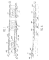
- a linear electroacoustic transmitting antenna comprises a flexible sheath section tubular 28 ( Figures 1, 2 and 3) whose ends are closed by end caps 74, 75 and which contains several electroacoustic transducers 31 as well than a fluid 32.
- the electroacoustic transducers 31 are kept at a fixed distance from each other by assembly cables 29 to which they are integral and are electrically connected to each other by cables electric 24, 79.
- Each end piece 74, 75 constitutes a device for connection of section 28 to another section (not shown) which may be an identical section or similar or a supply device 43 or else an acoustic reception module 47 (FIG. 6).
- section 28 may be an identical section or similar or a supply device 43 or else an acoustic reception module 47 (FIG. 6).
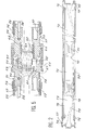
- Each electroacoustic transducer, source basic emission includes ( Figures 3 and 4) two electroacoustic motors 10 and 10A each comprising an equal number - in one embodiment preferential fourteen - piezoelectric ceramics 11. These motors are placed on either side of a central counterweight 12, and coaxially inside a housing 13, covering all of the motors 10 and 10A, up to pavilions 14 and 14A, located at the end of these. A volume 15 is thus delimited by pavilions 14 and 14A, and the housing 13.
- Piezoelectric ceramics can be replaced by bars of magnetostrictive materials.
- the electroacoustic motors 10 and 10A, and the intermediate counter 12, are held together by a prestressing rod 16.
- This rod is threaded to its ends to immobilize the two pavilions 14 and 14A, on the ends of the pillar thus formed at by means of the threads 17, 17A machined in the pavilions.
- An inner sleeve 20 isolates the prestressing rod motors 10 and 10A, and a sealing yoke 21, insulates the motors by compared to volume 15,
- the various fixing means are such that they allow freedom of movement, on the one hand ends of the electroacoustic motors on the side of the pavilion, and on the other hand, pavilions 14 and 14A, themselves, relative to the housing 13, so as to ensure full emission of acoustic waves in the environment ambient.
- Powering the 10 and 10A electroacoustic motors is supplied by 24 connected power cables to piezoelectric ceramics 11 by ramps supply 22, 22A and 23, 23A offset 90 ° by relative to the longitudinal axis of the motors. All of the connections is waterproof.
- volume 15 is partly occupied by baffles 25 and 25A maintained by retentions 26.
- baffles 25 and 25A are made of a cellular material with a density between 200 and 400 kg per m 3 in order to absorb, on the one hand, the rear radiation from the pavilions 14 and 14A and on the other hand the vibrations of the electroacoustic motors themselves which could radiate inside the volume 15.
- tubular passages 27 which will be used when filling the volume 15 , by a fluid described later.
- the flexible tubular sheath 28 ( Figures 3, 4 and 5) has by example, a thickness of about five millimeters and is made of polyurethane or a material resulting from a polyurethane blend for 80 to 95 parts and polyvinyl chloride (P.V.C.) for 20 to 5 parts.
- the sheath has a similar acoustic impedance that of the surrounding environment. It presents a good mechanical tensile strength and is flexible enough to be wrapped around the winch drum with a diameter of at least 1.30m without deformation of the internal volume of the sheath.
- the internal diameter is such that it can accommodate the electroacoustic transducer whose housing 13 has a slightly conical shape rounded ends 13A, 13B to allow it to slide at inside and center it.
- the method of placing in a sheath 28 of a electroacoustic emission transducer series 31 is the next.
- the transducers are fixed to cables 29 by known means such as olives crimped onto cables or molds profiles in the cabinet structure in which pass the cables blocked by a circular collar which crosses them.
- Two successive transducers are separated by a distance 30 which is equal to half the length emission wave.
- the sheath 28 is introduced into a tube called "vacuum tube" whose inner diameter is slightly higher than that of the sheath.
- vacuum tube After having sealing at both ends between the tube to vacuum and the sheath, we create the vacuum to press the sheath against the inner walls of the vacuum tube perfectly cylindrical and slightly expand it to facilitate the introduction of the transducer series whose assembly was previously carried out as described above.
- the introduction is carried out by means traction devices, winch type, pulling on cables 29 and driving the train of transducers to the inside of the sheath kept fixed in the tube to empty.
- a linear emissive antenna is thus produced which, to work, must be connected by a device for connection to a module supply of electrical frequency signals acoustic and have zero buoyancy.
- the emissive linear antenna must be able, if if necessary, be connected by a connection to a receiving antenna.
- a linear emissive antenna according to the invention can be consisting of several sections, each section comprising a plurality of transducers electroacoustics which are connected by connection devices.
- connection devices must be capable to perform mechanical functions, therefore to support the tensile force of the linear antenna by a boat, but also to make junctions electrical power supply and transmission of signals between different elements and between the different elements and the boat.
- the constituent materials must be compatible electrolytically with the operating environment, especially sea water and filling fluid.
- connection are two in number, on the one hand that 44, between the linear transmitting antenna according to the invention 45 and its power module 43 in electrical acoustic frequency signals, other share, that 46 between the linear transmitting antenna 45 and a receiving antenna 47.
- These devices connection can be of any known type and, especially like those described in French patents No. 2,529,397 and No. 2,584,874.
- Figure 5 is a longitudinal sectional view of such connection device which comprises a part female 50, fixed on the power supply module 43, or on the receiving antenna 47, and a male part 51, fixed on the linear antenna 45.
- the female parts and male are each equipped with the same notched end piece 52, whose outer diameter is compatible with the inner diameter of the sheath 28, limited by a stop 53, which determines the length of the introduction of the end piece in the sheath.
- the nozzle is also equipped with internal devices 54 for fixing cables 29 tractors intended on the one hand to take up the efforts of traction exerted on the sheath during towing and on the other hand to keep in position the train of transducers inside the sheath retaining a fixed interval between the transducers but in their allowing a slight rotation on themselves.
- the transducer train retained at each end by the devices 54 will be able balance the greater or lesser tension exerted successively on each of the four cables tractors 29, due to the curvature of the sheath 28, by a phenomenon of self-training in slight rotation internal transducers relative to each other in the sheath.
- the phenomenon is reversible and allows thus balancing the tension of the towing cables during the course of the linear antenna in its launching maneuver while retaining the interval between transducers, given to the transmission frequency.
- the male and female parts 51 and 50 are fixed on the sheath 28 by means of a crimped ring 56 compressing the sheath 28 on the notches 57.
- junction pins, variable number, plugs 59.60 males and females allow feeding electrical and antenna signal transmission according to the invention as well as the routing to the interior of said electrical energy antenna and signals to or from other transmitting modules or reception with which said antenna is connected.
- These junction pins are mounted on supports insulators 61 and 62 contained in bodies 63 and 64 of female and male parts.
- the support 61 is fixed while the support 62 is mobile in the longitudinal axis of the antenna.
- the support mobile 62 of the male part 51 includes a valve 65, intended to balance the pressures of the fluids of filling contained in the interconnected elements.
- This valve function is activated by means of the support mobile 62 whose translation can only take place when all the pins of junctions 59 and 60 are in engagement and that the interfacial joints 66, 67 are in contact, thanks to a return spring 68 calibrated in result.
- the female fixed support 61 has a passage 69 equipped with a valve allowing the circulation of the fluid in the male-female direction.
- a keying system ensures the connection mechanics between the male and female parts by known means, threads and notches provided with polarizers.
- connection devices between the antenna linear according to the invention, its power supply module electrical acoustic frequency signals to a end, a receiving antenna at the other end, are distinguished by the number of connection pins electrical and signals.
- the tips as well as the others systems are common to different devices connection.
- the power emitted by a transducer is linked, of a share, to the quantity of piezoelectric ceramics and, on the other hand, squared the coupling coefficient electromechanical between the roof and the engine electroacoustic which puts it in vibration.
- This electromechanical coupling coefficient itself depends the shape of the pillar, that of the pavilion, its elasticity, of the central mass and its assembly, knowing that a primordial factor is the elasticity of the flag.
- the parasitic frequency due to the deformation is a function Y / R , where R is the density of the material and Y its modulus of elasticity or Young, and of the shape of the pavilion knowing that to minimize the loss of energy due to this deformation, this parasitic frequency must be outside the working frequency range of the transducer.
- the choice of a density low does not change the resonant frequency and this especially since the central hub is reinforced by a rigid part which can be adapted to the desired shape of the pavilion and improves the rigidity of all.
- the central hub is reinforced by a rigid part which can be adapted to the desired shape of the pavilion and improves the rigidity of all.
- the mass m determines the weight and size constraints not to be exceeded, the factor on which we can act is therefore the elasticity e of the stack.
- the length L is also limited by space constraints not to be exceeded, the factor on which we can act to reduce the frequency of resonance by increasing elasticity so is the section S which must be reduced.
- the volume V is equal to the product of the length by the section transverse.
- the maximum length L is limited for reasons of space.
- the characteristics of the emissive transducer contained in the linear antenna according to the invention result optimization of physical constraints, acoustic and electric which have just been exposed. Given the choice of a very low frequency range, less than two kilohertz, the mass of the stack (ceramics 11, sheath 20, prestressing rod 16) and that of pavilions 14, 14A would reach 7.3 kg.
- the cellular material constituting the baffles 25 and 25A is a polyvinyl chloride foam which has the following characteristics: Density 300 kg per m 3 Crush resistance 7.4 MPa Tensile strength limit 8.7 MPa Shear coefficient 130 MPa Coefficient of expansion 30 * 10 -6 / ° C Thermal conductivity 0.053 W / m * ° C at 10 ° Cell size 0.2 millimeter
- the mass of the baffles 25 and 25A is 2.2 kg, or a total weight of the transducer in the air of 9.5 kg.
- the table below gives details of the materials used and the mass of the components. Designation Material Number Unit mass (in Kg) Total mass (in Kg) flag steel 2 2.4 4.8 scabbard teflon 1 0.01 0.01 ceramic P1.89 28 0.0232 0.65 prestressing rod 40CDV12 1 0.06 0.06 counterweight steel 1 1.8 1.8 speakers pvc foam 2 1.1 2.2 Total 9.52
- the inter-pavilion distance is therefore substantially equal to 300mm.
- the fluid is introduced through the valves 65 of the parts male connectors using a switchgear specific filling and degassing (no shown) exerting a force on the face of the support mobile 62 which causes it to move in translation along the longitudinal axis of the antenna, releasing the orifices of the valves 65 and making it possible to fill with a share the cavities of volume 15, not occupied by the baffles 25, 25A thanks to the tubular passages 27 of each of the transducers on the other hand to bridge the volumes 30 between the transducers and between the end transducers and connectors.
- a switchgear specific filling and degassing exerting a force on the face of the support mobile 62 which causes it to move in translation along the longitudinal axis of the antenna, releasing the orifices of the valves 65 and making it possible to fill with a share the cavities of volume 15, not occupied by the baffles 25, 25A thanks to the tubular passages 27 of each of the transducers on the other hand to bridge the volumes 30 between the trans
- Archimedes' thrust compensates for the mass of the antenna. Precise balancing of the antenna, for a density different filling fluid or a variation of the mass of the connectors, is operated by adjusting the density of the filling fluid, i.e. on the volume of the fluid within certain limits. It is also possible to replace the internal fluid, in said intervals, a density foam material lower than that of the fluid.
- the implementation of the linear antenna, according to the invention is operated from a boat 40 (figure 6), equipped with a winch 41, operating by means of motor means not shown, whose diameter winding of the empty drum is at least equal to 1.30m corresponding to the maximum curvature of the antenna without risk of deterioration.
- the linear transmitting antenna as well as the reception have zero buoyancy.
- the depth of use of these elements depends on the weight of the power carrier cable that is submerged for tow the whole, the weight of the electronic module agree as well as the speed of the towing boat.
- the linear antenna is more particularly intended to enter a system of anti-submarine fight lighter than systems known, requiring a simplified implementation, with acoustic performance and directivity improved.
Landscapes
- Life Sciences & Earth Sciences (AREA)
- Engineering & Computer Science (AREA)
- Physics & Mathematics (AREA)
- Remote Sensing (AREA)
- Environmental & Geological Engineering (AREA)
- Acoustics & Sound (AREA)
- Geology (AREA)
- General Life Sciences & Earth Sciences (AREA)
- General Physics & Mathematics (AREA)
- Geophysics (AREA)
- Mechanical Engineering (AREA)
- Oceanography (AREA)
- Transducers For Ultrasonic Waves (AREA)
Description
- les transducteurs électroacoustiques sont du type émissif et sont alimentés par des signaux électriques de fréquence acoustique,
- un dispositif d'alimentation, disposé d'un côté dudit tronçon, fournit lesdits signaux électriques de fréquence acoustique,
- au moins un dispositif de raccordement est disposé à une extrémité dudit tronçon pour permettre son raccordement mécanique et électrique à au moins ledit dispositif d'alimentation,
- chaque dispositif de raccordement est connecté par des conducteurs électriques aux transducteurs électroacoustiques disposés du côté opposé à celui dudit dispositif d'alimentation, et
- chaque tronçon de gaine souple est rempli d'un fluide dont la densité a été choisie pour obtenir la flottabilité nulle dudit tronçon.
- une antenne linéaire électroacoustique d'émission telle que définie ci-dessus,
- un module acoustique de réception, disposé dans le prolongement de l'antenne d'émission et comprenant des transducteurs électroacoustiques de type réceptif, pour détecter les signaux acoustiques en provenance de milieu aquatique et pour fournir des signaux électriques correspondants, et
- des moyens de connexion électrique pour transmettre lesdits signaux électriques fournis par les transducteurs électroacoustiques du module acoustique de réception à un système de traitement électronique.
- la figure 1 est un schéma de l'architecture d'une partie d'une antenne linéaire électroacoustique d'émission selon l'invention, vue en coupe longitudinale,
- la figure 2 est une vue en coupe longitudinale d'un exemple particulier de réalisation d'une antenne linéaire électroacoustique d'émission présentant des dispositifs de raccordement,
- la figure 3 est une vue en coupe longitudinale d'un transducteur électroacoustique d'émission pour une antenne linéaire selon l'invention,
- la figure 4 est une vue en coupe transversale selon la ligne IV-IV de la figure 3,
- la figure 5 est une vue en coupe longitudinale d'un dispositif de raccordement reliant l'antenne linéaire d'émission à un module d'alimentation ou à un module acoustique de réception, et
- la figure 6 est un schéma des éléments constitutifs d'un ensemble linéaire d'émission-réception.
| Densité | 300 kg par m3 |
| Résistance à l'écrasement | 7,4 MPa |
| Limite d'élasticité à la traction | 8,7 MPa |
| Coefficient de cisaillement | 130 MPa |
| Coefficient de dilatation | 30 * 10-6/°C |
| Conductivité thermique | 0,053 W/m*°C à 10° |
| Dimension des cellules | 0,2 millimètre |
| Désignation | Matière | Nombre | Masse unitaire (en Kg) | Masse totale (en Kg) |
| pavillon | acier | 2 | 2,4 | 4,8 |
| fourreau | téflon | 1 | 0,01 | 0,01 |
| céramique | P1.89 | 28 | 0,0232 | 0,65 |
| tige de précontrainte | 40CDV12 | 1 | 0,06 | 0,06 |
| contremasse | acier | 1 | 1,8 | 1,8 |
| baffles | mousse de P.V.C. | 2 | 1,1 | 2,2 |
| Total | 9,52 |
- il est très peu compressible;
- son inertie chimique est totale à l'égard des matériaux environnants tels que la gaine (polyuréthanne, polychlorure de vinyle), les isolants des fils de câblage, les boítiers et pièces mécaniques diverses, les transducteurs et matériau des baffles...;
- il présente une transparence acoustique telle que son impédance acoustique est égale à celle de l'eau;
- il n'est pas solidifiable aux températures basses (maxima -20°) et non transformable de façon irréversible aux températures élevées (jusqu'à 60°);
- sur le plan diélectrique, sa teneur en impuretés est limitée et sa rigidité diélectrique est inférieure à 5 kilovolts par millimètre;
- sa mise en oeuvre aux températures normales d'utilisation implique un coefficient de viscosité inférieur à 500 cst;
- pour des impératifs de sécurité, ininflammabilité en cas de fuite, son point éclair est élevé;
- il n'est pas toxique et présente une chaleur massique élevée (chaleur spécifique et conductibilité thermique élevées) afin de pouvoir conduire et évacuer les calories produites par le fonctionnement des moteurs piézo-électriques des transducteurs.
- cinq transducteurs dont la masse totale dans l'air est de 9,5kg et le volume de 8,41 litres,
- une gaine 72 réalisée dans un matériau comprenant des polychlorures de vinyle (P.V.C.), et du polyuréthanne (P.U.) dont la densité est de 1,24. La gaine présente donc une masse de 3,99kg pour 1 mètre de gaine et un volume intérieur de 31,41 litres pour 1 mètre de gaine,
- chaque transducteur est séparé du suivant par un intervalle 73,
- les deux dispositifs de raccordement 74 et 75 ont une masse de 9,5kg et un volume de 9,41 litres, ils sont sertis dans la gaine sur une longueur 76 de 15 cm, la partie hors gaine 77 mesure 10 cm, la distance entre les transducteurs d'extrémité et les demi-connecteurs 73 est de 300mm.
- les câbles tracteurs 78 sont au nombre de quatre, leur masse est de 57 grammes pour un mètre,
- les conducteurs électriques et coaxiaux 79, ont une masse de 500 grammes pour un mètre,
- le fluide de remplissage a une densité de 0,8,
- la valeur prise pour la densité de l'eau de mer est de
1,027.
BILAN des MASSES et des VOLUMES transducteurs 5 x 9,5 = 47,5 kg connecteurs 2 x 9,5 = 19,0 kg gaine 3,44m x 3,99 = 13,72 kg conducteurs électriques 3,44m x 0,500 = 1,72 kg câbles tracteurs 3,44m x 4 x 0,057 = 0,78 kg fluide de remplissage soit 6 intervalles de 300mm
1,80m x 31,41 l= 56,53 litres plus 5% du volume des transducteurs
5 x 8,4l x 5%= 2,10 litres TOTAL 58,63 litres DENSITE = 0,8 = 46,91 kg MASSE TOTALE 129,63 kg volume de la gaine 3,44 x 34,63 litres au mètre = 119,127 l volume des demi-connecteurs dépassant de la gaine 0,10 x 2 x 34,630 litres = 6,926 l VOLUME TOTAL 126,053 POUSSEE D'ARCHIMEDE X 1,027 = 129,45
- un module électronique d'accord 43, contenant notamment un dispositif d'alimentation en signaux de fréquence acoustique de l'antenne linéaire émissive, selon l'invention,
- un dispositif de raccordement ou connecteur 44 entre le module 43 et l'antenne émissive 45,
- l'antenne linéaire émissive proprement dite 45 dont la longueur peut être comprise entre 20 et 30 mètres,
- un dispositif de raccordement ou connecteur 46, entre l'antenne d'émission 45 et un module acoustique de réception à lever d'ambiguïté 47, non décrit,
- un connecteur 48, entre le module 47 et un autre module acoustique de plus grande longueur que le module 47, non décrit.
Claims (7)
- Antenne linéaire électroacoustique d'émission pour milieu aquatique qui comprend au moins un tronçon (28) de gaine souple fermée aux extrémités qui contient des transducteurs électroacoustiques (31) maintenus à une distance fixe l'un de l'autre par des câbles d'assemblage, caractérisée en ce que :lesdits transducteurs électroacoustiques (31) sont du type émissif et sont alimentés par des signaux électriques, de fréquence acoustique,un dispositif d'alimentation (43), disposé d'un côté dudit tronçon 28, fournit lesdits signaux électriques de fréquence acoustique,au moins un dispositif de raccordement est disposé à une extrémité dudit tronçon pour permettre son raccordement mécanique et électrique à au moins ledit dispositif d'alimentation,chaque dispositif de raccordement est connecté par des conducteurs électriques aux transducteurs électroacoustiques disposés du côté opposé à celui dudit dispositif d'alimentation, etau moins ledit tronçon de gaine souple est rempli d'un fluide (32) dont la densité a été choisie pour obtenir la flottabilité nulle dudit tronçon.
- Antenne linéaire électroacoustique d'émission selon la revendication 1, caractérisée en ce qu'elle comprend plusieurs tronçons de gaine souple contenant chacun une pluralité de transducteurs électroacoustiques, lesdits tronçons étant assemblés en série dans le prolongement l'un de l'autre par l'intermédiaire desdits dispositifs de raccordement.
- Antenne linéaire électroacoustique d'émission, selon les revendications 1 ou 2, caractérisée en ce que chaque transducteur électroacoustique comprend :deux moteurs électroacoustiques (10) (10A), constitués chacun d'un même nombre de céramiques piézo-électriques (11) jointives ou de barreaux de matériaux magnétostrictifs, placés de part et d'autre d'une contre-masse centrale (12),deux pavillons (14) (14A) situés chacun à une extrémité desdits moteurs,un dispositif d'assemblage précontraint desdits moteurs de part et d'autre de ladite contre-masse avec lesdits pavillons, au moyen d'une tige filetée (16) à ses extrémités immobilisant les deux pavillons et permettant de faire varier la précontrainte,un fourreau intérieur (20) pour isoler la tige filetée précontrainte (16) des moteurs (10) et (10A),une chape extérieure (21) pour isoler les moteurs (10) et (10A) par rapport au milieu ambiant,un dispositif étanche d'alimentation électrique desdits moteurs électroacoustiques au moyen de câbles d'alimentation électrique (24) raccordés aux céramiques piézo-électriques (11) par des rampes d'alimentation (22), (22A), (23), (23A), décalées de 90° par rapport à l'axe longitudinal des moteurs,deux baffles (25), (25A) constitués d'un matériau alvéolaire dans lequel seront ménagés des passages tubulaires (27), situés en arrière des pavillons (14), (14A) et maintenus en position autour des moteurs électroacoustiques (10), (10A) par des rétentions fixes (26), pour absorber le rayonnement acoustique arrière desdits pavillons ainsi que les vibrations desdits moteurs, etun boítier (13) enveloppant les baffles (25), (25A), laissant libre le déplacement longitudinal des pavillons (14), (14A), de forme conique arrondie à ses extrémités (13A), (13B) pour permettre le centrage du transducteur à l'intérieur d'une gaine tubulaire distincte dudit transducteur.
- Antenne linéaire électroacoustique d'émission selon les revendications 1 ou 2, caractérisée en ce que chaque dispositif de raccordement est constitué d'une partie femelle (50) et d'une partie mâle (51) de forme cylindrique comportant des moyens de raccordement mécanique et électrique qui comprennent respectivement :un embout cranté extérieurement (52) sur une distance limitée par une butée (53) qui détermine la longueur de recouvrement de l'embout par la gaine sertie au moyen d'une bague (56) sur les crans (57),ledit embout est équipé intérieurement de dispositifs (54) de fixation des câbles tracteurs (29) pour reprendre les efforts de traction exercés sur la gaine,des broches de jonction en nombre variable (59), (60) pour l'alimentation électrique et la transmission des signaux, montées sur des supports isolants (61), (62) contenus dans les corps (63), (64) des parties femelle et mâle,un dispositif de remplissage de la gaine par un fluide en surpression et d'équilibrage des pressions, dudit fluide entre les éléments interconnectés, au moyen d'une valve (65) incluse dans le support mobile (62) dont la translation ne peut s'effectuer que lorsque toutes les broches de jonction (59), (60) sont en prise et que les joints interfaciaux (66), (67) sont en contact grâce à un ressort de rappel (68), taré en conséquence, le support fixe (61) comportant lui-même un passage (69) avec valve autorisant la circulation du fluide dans le sens mâle-femelle, etun système de clavetage, pour assurer la liaison mécanique entre les parties mâle et femelle, par des moyens connus tels que filetages et crans munis de détrompeurs.
- Antenne d'émission-réception électroacoustique pour milieu aquatique, caractérisée en ce qu'elle comprend :une antenne linéaire électroacoustique d'émission (45) selon l'une quelconque des revendications précédentes,un module acoustique de réception (47), disposé dans le prolongement de la dite antenne d'émission et comprenant des transducteurs électroacoustiques de type réceptif, pour détecter les signaux acoustiques en provenance du milieu aquatique et pour fournir des signaux électriques correspondants, etdes moyens de connexion électrique pour transmettre lesdits signaux électriques fournis par les transducteurs électroacoustiques dudit module acoustique de réception à un système de traitement électronique.
- Antenne d'émission-réception électroacoustique selon la revendication 5, caractérisée en ce que ledit module acoustique de réception (47) est raccordé au moins mécaniquement à ladite antenne linéaire électroacoustique d'émission (45) par un dispositif de raccordement mécanique.
- Antenne d'émission-réception électroacoustique selon la revendication 6, caractérisée en ce que les moyens de connexion électrique comprennent des conducteurs électriques qui sont disposés dans chaque tronçon de ladite antenne linéaire électroacoustique d'émission et sont connectés entre eux par l'intermédiaire desdits dispositifs de raccordement de tronçon.
Priority Applications (3)
| Application Number | Priority Date | Filing Date | Title |
|---|---|---|---|
| FR9415109A FR2728425B1 (fr) | 1994-12-15 | 1994-12-15 | Antenne lineaire electroacoustique d'emission et antenne d'emission/reception comprenant une telle antenne |
| DE1995618851 DE69518851T2 (de) | 1995-12-21 | 1995-12-21 | Lineare akustische Sendeantenne und dazugehörige Sende-Empfangsantenne |
| EP95402892A EP0782010B1 (fr) | 1994-12-15 | 1995-12-21 | Antenne linéaire électroacoustique d'émission et antenne d'émission/réception comprenant une telle antenne |
Applications Claiming Priority (2)
| Application Number | Priority Date | Filing Date | Title |
|---|---|---|---|
| FR9415109A FR2728425B1 (fr) | 1994-12-15 | 1994-12-15 | Antenne lineaire electroacoustique d'emission et antenne d'emission/reception comprenant une telle antenne |
| EP95402892A EP0782010B1 (fr) | 1994-12-15 | 1995-12-21 | Antenne linéaire électroacoustique d'émission et antenne d'émission/réception comprenant une telle antenne |
Publications (2)
| Publication Number | Publication Date |
|---|---|
| EP0782010A1 EP0782010A1 (fr) | 1997-07-02 |
| EP0782010B1 true EP0782010B1 (fr) | 2000-09-13 |
Family
ID=26140604
Family Applications (1)
| Application Number | Title | Priority Date | Filing Date |
|---|---|---|---|
| EP95402892A Expired - Lifetime EP0782010B1 (fr) | 1994-12-15 | 1995-12-21 | Antenne linéaire électroacoustique d'émission et antenne d'émission/réception comprenant une telle antenne |
Country Status (2)
| Country | Link |
|---|---|
| EP (1) | EP0782010B1 (fr) |
| FR (1) | FR2728425B1 (fr) |
Families Citing this family (7)
| Publication number | Priority date | Publication date | Assignee | Title |
|---|---|---|---|---|
| FR2779533B1 (fr) * | 1998-06-09 | 2000-08-25 | Total Sa | Dispositif d'acquisition sismique a haute resolution |
| FR2800879B1 (fr) * | 1999-11-09 | 2007-03-02 | France Etat | Procedes et dispositifs associes de determination de la forme d'une antenne lineaire et de lever d'ambiguite conique |
| GB0010636D0 (en) * | 2000-05-04 | 2000-06-28 | Geco As | Acoustic emitters for use in marine seismic surveying |
| DE102004038034A1 (de) * | 2004-08-05 | 2006-02-23 | Atlas Elektronik Gmbh | Elektroakustische Sendeantenne |
| CN108788159A (zh) * | 2018-07-17 | 2018-11-13 | 太原理工大学 | 一种超声波辅助热压烧结炉 |
| CN109488191B (zh) * | 2018-12-25 | 2024-12-13 | 浙江联大科技有限公司 | 具有可选择反射结构的陶瓷天线的窗帘电机 |
| FR3115953B1 (fr) * | 2020-11-05 | 2022-10-28 | Thales Sa | Dispositif de réception d'ondes acoustiques |
Family Cites Families (12)
| Publication number | Priority date | Publication date | Assignee | Title |
|---|---|---|---|---|
| FR2302656A1 (fr) * | 1975-02-27 | 1976-09-24 | France Etat | Transducteur piezoelectrique pour basses frequences |
| US4160229A (en) * | 1976-07-08 | 1979-07-03 | Honeywell Inc. | Concentric tube hydrophone streamer |
| FR2525373A1 (fr) * | 1982-04-20 | 1983-10-21 | Saint Gaudens Atel Meca | Element de flute marine a organes separateurs |
| NO860780L (no) * | 1985-03-05 | 1986-09-08 | Exxon Production Research Co | N oppstilling av marine seismiske kilder. |
| FR2584874B1 (fr) * | 1985-07-10 | 1988-04-22 | Saint Gaudens Ateliers Mecaniq | Dispositif de connexion electrique du type comprenant une gaine apte a contenir un fluide de remplissage notamment pour flutes sismiques |
| US4876675A (en) * | 1987-09-12 | 1989-10-24 | Ngk Spark Plug Co., Ltd. | Towed piezoelectric cable |
| FR2660513B1 (fr) * | 1990-04-03 | 1993-04-23 | Thomson Csf | Jonction pour antenne acoustique lineaire sous-marine remorquee. |
| FR2663182B1 (fr) * | 1990-06-12 | 1992-09-18 | Grosso Gilles | Transducteur electro-acoustique immerge. |
| FR2670350B1 (fr) * | 1990-12-11 | 1995-06-16 | Thomson Csf | Troncon pour antenne acoustique lineaire et antenne formee d'une ensemble de tels troncons. |
| GB9103531D0 (en) * | 1991-02-20 | 1991-05-22 | Gec Ferranti Defence Syst | Testing linear arrays |
| DE4208178C2 (de) * | 1992-03-14 | 1994-07-21 | Prakla Seismos Gmbh | Marineseismischer Streamer |
| FR2697709B1 (fr) * | 1992-11-05 | 1994-12-30 | France Etat Armement | Dispositif d'étanchéité de moteurs électro-acoustiques. |
-
1994
- 1994-12-15 FR FR9415109A patent/FR2728425B1/fr not_active Expired - Fee Related
-
1995
- 1995-12-21 EP EP95402892A patent/EP0782010B1/fr not_active Expired - Lifetime
Also Published As
| Publication number | Publication date |
|---|---|
| FR2728425B1 (fr) | 1997-01-31 |
| EP0782010A1 (fr) | 1997-07-02 |
| FR2728425A1 (fr) | 1996-06-21 |
Similar Documents
| Publication | Publication Date | Title |
|---|---|---|
| EP2151700B1 (fr) | Flûte sismique formée de sections comprenant une gaine principale revêtue d'une gaine externe formée d'un matériau thermoplastique chargé par un matériau biocide | |
| EP2625741B1 (fr) | Antenne de grande dimension à ondes de surface et à large bande | |
| EP3455536A1 (fr) | Dispositif chauffant pour le transport d'un mélange multiphasique d'hydrocarbures et procédé associé | |
| FR3000564A1 (fr) | Procede et systeme d'extremite avant a barre rigide | |
| CA1297579C (fr) | Transducteur piezo-electrique comportant plusieurs elements sensibles coaxiaux | |
| OA11402A (fr) | Conduite sous-marine de transfert de produits péroliers. | |
| FR3000563A1 (fr) | Procede et systeme de recherche a barre rigide | |
| FR2975071A1 (fr) | Procede et systeme de bouee composite | |
| EP0782010A1 (fr) | Antenne linéaire électroacoustique d'émission et antenne d'émission/réception comprenant une telle antenne | |
| FR2958619A1 (fr) | Flute marine ayant une amelioration de la rigidite activee par pression | |
| FR2558664A1 (fr) | Repeteurs, notamment numeriques, pour circuit de transmission optique notamment sous-marin | |
| WO2003060368A1 (fr) | Conduite rigide enroulable chauffée pour le transport des fluides, notamment d'hydrocarbures. | |
| EP2401468B1 (fr) | Installation de liaison fond-surface de type tour hybride multi-riser comprenant des modules de flottabilite coulissants | |
| EP0684084B1 (fr) | Procédé et transducteur pour émettre des ondes acoustiques à larges bandes et basses fréquences en profondeur d'immersion illimitée | |
| FR2695906A1 (fr) | Association vaisseau spatial-lanceur et pièce de transition pour cette association. | |
| FR2921996A1 (fr) | Dispositif de jonction isolee entre deux troncons de tuyau double enveloppe | |
| EP0208596B1 (fr) | Amortisseur de vibrations pour corps remorqué | |
| EP0375498B1 (fr) | Antenne hydrophonique linéaire modulaire directionnelle | |
| FR2797552A1 (fr) | Transducteur electro-acoustique | |
| WO2010037937A1 (fr) | Antennes laterales d'emission acoustique pour prospection sismique sous marine | |
| FR3003358A1 (fr) | Dispositif de distribution de fluide | |
| FR2548387A1 (fr) | Ensemble flottant allonge destine a supporter plusieurs sources sismiques et dispositif de sources sismiques | |
| CA2109465C (fr) | Dispositif d'etancheite de moteurs electro-acoustiques | |
| EP0794841B1 (fr) | Antenne de sonar presentant des pics de sensibilite au moins a deux frequences | |
| EP0728534B1 (fr) | Procédé et transducteurs immergés dans un fluide pour l'émission d'ondes acoustiques à basse fréquence avec des pavillons allégés |
Legal Events
| Date | Code | Title | Description |
|---|---|---|---|
| PUAI | Public reference made under article 153(3) epc to a published international application that has entered the european phase |
Free format text: ORIGINAL CODE: 0009012 |
|
| 17P | Request for examination filed |
Effective date: 19960301 |
|
| AK | Designated contracting states |
Kind code of ref document: A1 Designated state(s): DE GB |
|
| GRAG | Despatch of communication of intention to grant |
Free format text: ORIGINAL CODE: EPIDOS AGRA |
|
| GRAG | Despatch of communication of intention to grant |
Free format text: ORIGINAL CODE: EPIDOS AGRA |
|
| GRAH | Despatch of communication of intention to grant a patent |
Free format text: ORIGINAL CODE: EPIDOS IGRA |
|
| 17Q | First examination report despatched |
Effective date: 20000127 |
|
| GRAH | Despatch of communication of intention to grant a patent |
Free format text: ORIGINAL CODE: EPIDOS IGRA |
|
| GRAA | (expected) grant |
Free format text: ORIGINAL CODE: 0009210 |
|
| AK | Designated contracting states |
Kind code of ref document: B1 Designated state(s): DE GB |
|
| GBT | Gb: translation of ep patent filed (gb section 77(6)(a)/1977) |
Effective date: 20000914 |
|
| REF | Corresponds to: |
Ref document number: 69518851 Country of ref document: DE Date of ref document: 20001019 |
|
| PLBE | No opposition filed within time limit |
Free format text: ORIGINAL CODE: 0009261 |
|
| STAA | Information on the status of an ep patent application or granted ep patent |
Free format text: STATUS: NO OPPOSITION FILED WITHIN TIME LIMIT |
|
| 26N | No opposition filed | ||
| REG | Reference to a national code |
Ref country code: GB Ref legal event code: IF02 |
|
| PGFP | Annual fee paid to national office [announced via postgrant information from national office to epo] |
Ref country code: GB Payment date: 20021210 Year of fee payment: 8 |
|
| PGFP | Annual fee paid to national office [announced via postgrant information from national office to epo] |
Ref country code: DE Payment date: 20030225 Year of fee payment: 8 |
|
| PG25 | Lapsed in a contracting state [announced via postgrant information from national office to epo] |
Ref country code: GB Free format text: LAPSE BECAUSE OF NON-PAYMENT OF DUE FEES Effective date: 20031221 |
|
| PG25 | Lapsed in a contracting state [announced via postgrant information from national office to epo] |
Ref country code: DE Free format text: LAPSE BECAUSE OF NON-PAYMENT OF DUE FEES Effective date: 20040701 |
|
| GBPC | Gb: european patent ceased through non-payment of renewal fee |
Effective date: 20031221 |