EP0781532A2 - Implantable device with inner electrode - Google Patents
Implantable device with inner electrode Download PDFInfo
- Publication number
- EP0781532A2 EP0781532A2 EP96119232A EP96119232A EP0781532A2 EP 0781532 A2 EP0781532 A2 EP 0781532A2 EP 96119232 A EP96119232 A EP 96119232A EP 96119232 A EP96119232 A EP 96119232A EP 0781532 A2 EP0781532 A2 EP 0781532A2
- Authority
- EP
- European Patent Office
- Prior art keywords
- cavity
- electrode
- coil
- shaft
- electrodes
- Prior art date
- Legal status (The legal status is an assumption and is not a legal conclusion. Google has not performed a legal analysis and makes no representation as to the accuracy of the status listed.)
- Granted
Links
Images


Classifications
-
- A—HUMAN NECESSITIES
- A61—MEDICAL OR VETERINARY SCIENCE; HYGIENE
- A61N—ELECTROTHERAPY; MAGNETOTHERAPY; RADIATION THERAPY; ULTRASOUND THERAPY
- A61N1/00—Electrotherapy; Circuits therefor
- A61N1/18—Applying electric currents by contact electrodes
- A61N1/32—Applying electric currents by contact electrodes alternating or intermittent currents
- A61N1/326—Applying electric currents by contact electrodes alternating or intermittent currents for promoting growth of cells, e.g. bone cells
-
- A—HUMAN NECESSITIES
- A61—MEDICAL OR VETERINARY SCIENCE; HYGIENE
- A61B—DIAGNOSIS; SURGERY; IDENTIFICATION
- A61B17/00—Surgical instruments, devices or methods, e.g. tourniquets
- A61B17/56—Surgical instruments or methods for treatment of bones or joints; Devices specially adapted therefor
- A61B17/58—Surgical instruments or methods for treatment of bones or joints; Devices specially adapted therefor for osteosynthesis, e.g. bone plates, screws, setting implements or the like
- A61B17/68—Internal fixation devices, including fasteners and spinal fixators, even if a part thereof projects from the skin
- A61B17/72—Intramedullary pins, nails or other devices
-
- A—HUMAN NECESSITIES
- A61—MEDICAL OR VETERINARY SCIENCE; HYGIENE
- A61C—DENTISTRY; APPARATUS OR METHODS FOR ORAL OR DENTAL HYGIENE
- A61C8/00—Means to be fixed to the jaw-bone for consolidating natural teeth or for fixing dental prostheses thereon; Dental implants; Implanting tools
-
- A—HUMAN NECESSITIES
- A61—MEDICAL OR VETERINARY SCIENCE; HYGIENE
- A61C—DENTISTRY; APPARATUS OR METHODS FOR ORAL OR DENTAL HYGIENE
- A61C8/00—Means to be fixed to the jaw-bone for consolidating natural teeth or for fixing dental prostheses thereon; Dental implants; Implanting tools
- A61C8/0003—Not used, see subgroups
- A61C8/0004—Consolidating natural teeth
- A61C8/0006—Periodontal tissue or bone regeneration
- A61C8/0007—Stimulation of growth around implant by electrical means
-
- A—HUMAN NECESSITIES
- A61—MEDICAL OR VETERINARY SCIENCE; HYGIENE
- A61F—FILTERS IMPLANTABLE INTO BLOOD VESSELS; PROSTHESES; DEVICES PROVIDING PATENCY TO, OR PREVENTING COLLAPSING OF, TUBULAR STRUCTURES OF THE BODY, e.g. STENTS; ORTHOPAEDIC, NURSING OR CONTRACEPTIVE DEVICES; FOMENTATION; TREATMENT OR PROTECTION OF EYES OR EARS; BANDAGES, DRESSINGS OR ABSORBENT PADS; FIRST-AID KITS
- A61F2/00—Filters implantable into blood vessels; Prostheses, i.e. artificial substitutes or replacements for parts of the body; Appliances for connecting them with the body; Devices providing patency to, or preventing collapsing of, tubular structures of the body, e.g. stents
- A61F2/02—Prostheses implantable into the body
- A61F2/30—Joints
- A61F2/32—Joints for the hip
- A61F2/34—Acetabular cups
-
- A—HUMAN NECESSITIES
- A61—MEDICAL OR VETERINARY SCIENCE; HYGIENE
- A61F—FILTERS IMPLANTABLE INTO BLOOD VESSELS; PROSTHESES; DEVICES PROVIDING PATENCY TO, OR PREVENTING COLLAPSING OF, TUBULAR STRUCTURES OF THE BODY, e.g. STENTS; ORTHOPAEDIC, NURSING OR CONTRACEPTIVE DEVICES; FOMENTATION; TREATMENT OR PROTECTION OF EYES OR EARS; BANDAGES, DRESSINGS OR ABSORBENT PADS; FIRST-AID KITS
- A61F2/00—Filters implantable into blood vessels; Prostheses, i.e. artificial substitutes or replacements for parts of the body; Appliances for connecting them with the body; Devices providing patency to, or preventing collapsing of, tubular structures of the body, e.g. stents
- A61F2/02—Prostheses implantable into the body
- A61F2/30—Joints
- A61F2/32—Joints for the hip
- A61F2/36—Femoral heads ; Femoral endoprostheses
- A61F2/3662—Femoral shafts
-
- A—HUMAN NECESSITIES
- A61—MEDICAL OR VETERINARY SCIENCE; HYGIENE
- A61F—FILTERS IMPLANTABLE INTO BLOOD VESSELS; PROSTHESES; DEVICES PROVIDING PATENCY TO, OR PREVENTING COLLAPSING OF, TUBULAR STRUCTURES OF THE BODY, e.g. STENTS; ORTHOPAEDIC, NURSING OR CONTRACEPTIVE DEVICES; FOMENTATION; TREATMENT OR PROTECTION OF EYES OR EARS; BANDAGES, DRESSINGS OR ABSORBENT PADS; FIRST-AID KITS
- A61F2/00—Filters implantable into blood vessels; Prostheses, i.e. artificial substitutes or replacements for parts of the body; Appliances for connecting them with the body; Devices providing patency to, or preventing collapsing of, tubular structures of the body, e.g. stents
- A61F2/02—Prostheses implantable into the body
- A61F2/30—Joints
- A61F2/38—Joints for elbows or knees
- A61F2/3804—Joints for elbows or knees for elbows
-
- A—HUMAN NECESSITIES
- A61—MEDICAL OR VETERINARY SCIENCE; HYGIENE
- A61F—FILTERS IMPLANTABLE INTO BLOOD VESSELS; PROSTHESES; DEVICES PROVIDING PATENCY TO, OR PREVENTING COLLAPSING OF, TUBULAR STRUCTURES OF THE BODY, e.g. STENTS; ORTHOPAEDIC, NURSING OR CONTRACEPTIVE DEVICES; FOMENTATION; TREATMENT OR PROTECTION OF EYES OR EARS; BANDAGES, DRESSINGS OR ABSORBENT PADS; FIRST-AID KITS
- A61F2/00—Filters implantable into blood vessels; Prostheses, i.e. artificial substitutes or replacements for parts of the body; Appliances for connecting them with the body; Devices providing patency to, or preventing collapsing of, tubular structures of the body, e.g. stents
- A61F2/02—Prostheses implantable into the body
- A61F2/30—Joints
- A61F2/44—Joints for the spine, e.g. vertebrae, spinal discs
- A61F2/4455—Joints for the spine, e.g. vertebrae, spinal discs for the fusion of spinal bodies, e.g. intervertebral fusion of adjacent spinal bodies, e.g. fusion cages
- A61F2/446—Joints for the spine, e.g. vertebrae, spinal discs for the fusion of spinal bodies, e.g. intervertebral fusion of adjacent spinal bodies, e.g. fusion cages having a circular or elliptical cross-section substantially parallel to the axis of the spine, e.g. cylinders or frustocones
-
- A—HUMAN NECESSITIES
- A61—MEDICAL OR VETERINARY SCIENCE; HYGIENE
- A61N—ELECTROTHERAPY; MAGNETOTHERAPY; RADIATION THERAPY; ULTRASOUND THERAPY
- A61N1/00—Electrotherapy; Circuits therefor
- A61N1/02—Details
- A61N1/04—Electrodes
- A61N1/05—Electrodes for implantation or insertion into the body, e.g. heart electrode
-
- A—HUMAN NECESSITIES
- A61—MEDICAL OR VETERINARY SCIENCE; HYGIENE
- A61B—DIAGNOSIS; SURGERY; IDENTIFICATION
- A61B17/00—Surgical instruments, devices or methods, e.g. tourniquets
- A61B17/56—Surgical instruments or methods for treatment of bones or joints; Devices specially adapted therefor
- A61B17/58—Surgical instruments or methods for treatment of bones or joints; Devices specially adapted therefor for osteosynthesis, e.g. bone plates, screws, setting implements or the like
- A61B17/68—Internal fixation devices, including fasteners and spinal fixators, even if a part thereof projects from the skin
- A61B17/72—Intramedullary pins, nails or other devices
- A61B17/7216—Intramedullary pins, nails or other devices for bone lengthening or compression
-
- A—HUMAN NECESSITIES
- A61—MEDICAL OR VETERINARY SCIENCE; HYGIENE
- A61F—FILTERS IMPLANTABLE INTO BLOOD VESSELS; PROSTHESES; DEVICES PROVIDING PATENCY TO, OR PREVENTING COLLAPSING OF, TUBULAR STRUCTURES OF THE BODY, e.g. STENTS; ORTHOPAEDIC, NURSING OR CONTRACEPTIVE DEVICES; FOMENTATION; TREATMENT OR PROTECTION OF EYES OR EARS; BANDAGES, DRESSINGS OR ABSORBENT PADS; FIRST-AID KITS
- A61F2/00—Filters implantable into blood vessels; Prostheses, i.e. artificial substitutes or replacements for parts of the body; Appliances for connecting them with the body; Devices providing patency to, or preventing collapsing of, tubular structures of the body, e.g. stents
- A61F2/02—Prostheses implantable into the body
- A61F2/30—Joints
- A61F2/30721—Accessories
- A61F2/30724—Spacers for centering an implant in a bone cavity, e.g. in a cement-receiving cavity
-
- A—HUMAN NECESSITIES
- A61—MEDICAL OR VETERINARY SCIENCE; HYGIENE
- A61F—FILTERS IMPLANTABLE INTO BLOOD VESSELS; PROSTHESES; DEVICES PROVIDING PATENCY TO, OR PREVENTING COLLAPSING OF, TUBULAR STRUCTURES OF THE BODY, e.g. STENTS; ORTHOPAEDIC, NURSING OR CONTRACEPTIVE DEVICES; FOMENTATION; TREATMENT OR PROTECTION OF EYES OR EARS; BANDAGES, DRESSINGS OR ABSORBENT PADS; FIRST-AID KITS
- A61F2/00—Filters implantable into blood vessels; Prostheses, i.e. artificial substitutes or replacements for parts of the body; Appliances for connecting them with the body; Devices providing patency to, or preventing collapsing of, tubular structures of the body, e.g. stents
- A61F2/02—Prostheses implantable into the body
- A61F2/30—Joints
- A61F2/30721—Accessories
- A61F2/30744—End caps, e.g. for closing an endoprosthetic cavity
-
- A—HUMAN NECESSITIES
- A61—MEDICAL OR VETERINARY SCIENCE; HYGIENE
- A61F—FILTERS IMPLANTABLE INTO BLOOD VESSELS; PROSTHESES; DEVICES PROVIDING PATENCY TO, OR PREVENTING COLLAPSING OF, TUBULAR STRUCTURES OF THE BODY, e.g. STENTS; ORTHOPAEDIC, NURSING OR CONTRACEPTIVE DEVICES; FOMENTATION; TREATMENT OR PROTECTION OF EYES OR EARS; BANDAGES, DRESSINGS OR ABSORBENT PADS; FIRST-AID KITS
- A61F2/00—Filters implantable into blood vessels; Prostheses, i.e. artificial substitutes or replacements for parts of the body; Appliances for connecting them with the body; Devices providing patency to, or preventing collapsing of, tubular structures of the body, e.g. stents
- A61F2/02—Prostheses implantable into the body
- A61F2/30—Joints
- A61F2/30767—Special external or bone-contacting surface, e.g. coating for improving bone ingrowth
-
- A—HUMAN NECESSITIES
- A61—MEDICAL OR VETERINARY SCIENCE; HYGIENE
- A61F—FILTERS IMPLANTABLE INTO BLOOD VESSELS; PROSTHESES; DEVICES PROVIDING PATENCY TO, OR PREVENTING COLLAPSING OF, TUBULAR STRUCTURES OF THE BODY, e.g. STENTS; ORTHOPAEDIC, NURSING OR CONTRACEPTIVE DEVICES; FOMENTATION; TREATMENT OR PROTECTION OF EYES OR EARS; BANDAGES, DRESSINGS OR ABSORBENT PADS; FIRST-AID KITS
- A61F2/00—Filters implantable into blood vessels; Prostheses, i.e. artificial substitutes or replacements for parts of the body; Appliances for connecting them with the body; Devices providing patency to, or preventing collapsing of, tubular structures of the body, e.g. stents
- A61F2/02—Prostheses implantable into the body
- A61F2/30—Joints
- A61F2/32—Joints for the hip
- A61F2/36—Femoral heads ; Femoral endoprostheses
- A61F2/3662—Femoral shafts
- A61F2/367—Proximal or metaphyseal parts of shafts
-
- A—HUMAN NECESSITIES
- A61—MEDICAL OR VETERINARY SCIENCE; HYGIENE
- A61F—FILTERS IMPLANTABLE INTO BLOOD VESSELS; PROSTHESES; DEVICES PROVIDING PATENCY TO, OR PREVENTING COLLAPSING OF, TUBULAR STRUCTURES OF THE BODY, e.g. STENTS; ORTHOPAEDIC, NURSING OR CONTRACEPTIVE DEVICES; FOMENTATION; TREATMENT OR PROTECTION OF EYES OR EARS; BANDAGES, DRESSINGS OR ABSORBENT PADS; FIRST-AID KITS
- A61F2/00—Filters implantable into blood vessels; Prostheses, i.e. artificial substitutes or replacements for parts of the body; Appliances for connecting them with the body; Devices providing patency to, or preventing collapsing of, tubular structures of the body, e.g. stents
- A61F2/02—Prostheses implantable into the body
- A61F2/30—Joints
- A61F2/44—Joints for the spine, e.g. vertebrae, spinal discs
- A61F2/442—Intervertebral or spinal discs, e.g. resilient
-
- A—HUMAN NECESSITIES
- A61—MEDICAL OR VETERINARY SCIENCE; HYGIENE
- A61F—FILTERS IMPLANTABLE INTO BLOOD VESSELS; PROSTHESES; DEVICES PROVIDING PATENCY TO, OR PREVENTING COLLAPSING OF, TUBULAR STRUCTURES OF THE BODY, e.g. STENTS; ORTHOPAEDIC, NURSING OR CONTRACEPTIVE DEVICES; FOMENTATION; TREATMENT OR PROTECTION OF EYES OR EARS; BANDAGES, DRESSINGS OR ABSORBENT PADS; FIRST-AID KITS
- A61F2/00—Filters implantable into blood vessels; Prostheses, i.e. artificial substitutes or replacements for parts of the body; Appliances for connecting them with the body; Devices providing patency to, or preventing collapsing of, tubular structures of the body, e.g. stents
- A61F2/02—Prostheses implantable into the body
- A61F2/30—Joints
- A61F2/46—Special tools or methods for implanting or extracting artificial joints, accessories, bone grafts or substitutes, or particular adaptations therefor
- A61F2/4603—Special tools or methods for implanting or extracting artificial joints, accessories, bone grafts or substitutes, or particular adaptations therefor for insertion or extraction of endoprosthetic joints or of accessories thereof
- A61F2/4607—Special tools or methods for implanting or extracting artificial joints, accessories, bone grafts or substitutes, or particular adaptations therefor for insertion or extraction of endoprosthetic joints or of accessories thereof of hip femoral endoprostheses
-
- A—HUMAN NECESSITIES
- A61—MEDICAL OR VETERINARY SCIENCE; HYGIENE
- A61F—FILTERS IMPLANTABLE INTO BLOOD VESSELS; PROSTHESES; DEVICES PROVIDING PATENCY TO, OR PREVENTING COLLAPSING OF, TUBULAR STRUCTURES OF THE BODY, e.g. STENTS; ORTHOPAEDIC, NURSING OR CONTRACEPTIVE DEVICES; FOMENTATION; TREATMENT OR PROTECTION OF EYES OR EARS; BANDAGES, DRESSINGS OR ABSORBENT PADS; FIRST-AID KITS
- A61F2/00—Filters implantable into blood vessels; Prostheses, i.e. artificial substitutes or replacements for parts of the body; Appliances for connecting them with the body; Devices providing patency to, or preventing collapsing of, tubular structures of the body, e.g. stents
- A61F2/02—Prostheses implantable into the body
- A61F2/28—Bones
- A61F2002/2821—Bone stimulation by electromagnetic fields or electric current for enhancing ossification
-
- A—HUMAN NECESSITIES
- A61—MEDICAL OR VETERINARY SCIENCE; HYGIENE
- A61F—FILTERS IMPLANTABLE INTO BLOOD VESSELS; PROSTHESES; DEVICES PROVIDING PATENCY TO, OR PREVENTING COLLAPSING OF, TUBULAR STRUCTURES OF THE BODY, e.g. STENTS; ORTHOPAEDIC, NURSING OR CONTRACEPTIVE DEVICES; FOMENTATION; TREATMENT OR PROTECTION OF EYES OR EARS; BANDAGES, DRESSINGS OR ABSORBENT PADS; FIRST-AID KITS
- A61F2/00—Filters implantable into blood vessels; Prostheses, i.e. artificial substitutes or replacements for parts of the body; Appliances for connecting them with the body; Devices providing patency to, or preventing collapsing of, tubular structures of the body, e.g. stents
- A61F2/02—Prostheses implantable into the body
- A61F2/28—Bones
- A61F2002/2835—Bone graft implants for filling a bony defect or an endoprosthesis cavity, e.g. by synthetic material or biological material
-
- A—HUMAN NECESSITIES
- A61—MEDICAL OR VETERINARY SCIENCE; HYGIENE
- A61F—FILTERS IMPLANTABLE INTO BLOOD VESSELS; PROSTHESES; DEVICES PROVIDING PATENCY TO, OR PREVENTING COLLAPSING OF, TUBULAR STRUCTURES OF THE BODY, e.g. STENTS; ORTHOPAEDIC, NURSING OR CONTRACEPTIVE DEVICES; FOMENTATION; TREATMENT OR PROTECTION OF EYES OR EARS; BANDAGES, DRESSINGS OR ABSORBENT PADS; FIRST-AID KITS
- A61F2/00—Filters implantable into blood vessels; Prostheses, i.e. artificial substitutes or replacements for parts of the body; Appliances for connecting them with the body; Devices providing patency to, or preventing collapsing of, tubular structures of the body, e.g. stents
- A61F2/02—Prostheses implantable into the body
- A61F2/30—Joints
- A61F2002/30001—Additional features of subject-matter classified in A61F2/28, A61F2/30 and subgroups thereof
- A61F2002/30003—Material related properties of the prosthesis or of a coating on the prosthesis
- A61F2002/3006—Properties of materials and coating materials
- A61F2002/30062—(bio)absorbable, biodegradable, bioerodable, (bio)resorbable, resorptive
-
- A—HUMAN NECESSITIES
- A61—MEDICAL OR VETERINARY SCIENCE; HYGIENE
- A61F—FILTERS IMPLANTABLE INTO BLOOD VESSELS; PROSTHESES; DEVICES PROVIDING PATENCY TO, OR PREVENTING COLLAPSING OF, TUBULAR STRUCTURES OF THE BODY, e.g. STENTS; ORTHOPAEDIC, NURSING OR CONTRACEPTIVE DEVICES; FOMENTATION; TREATMENT OR PROTECTION OF EYES OR EARS; BANDAGES, DRESSINGS OR ABSORBENT PADS; FIRST-AID KITS
- A61F2/00—Filters implantable into blood vessels; Prostheses, i.e. artificial substitutes or replacements for parts of the body; Appliances for connecting them with the body; Devices providing patency to, or preventing collapsing of, tubular structures of the body, e.g. stents
- A61F2/02—Prostheses implantable into the body
- A61F2/30—Joints
- A61F2002/30001—Additional features of subject-matter classified in A61F2/28, A61F2/30 and subgroups thereof
- A61F2002/30108—Shapes
- A61F2002/3011—Cross-sections or two-dimensional shapes
- A61F2002/30138—Convex polygonal shapes
- A61F2002/30143—Convex polygonal shapes hexagonal
-
- A—HUMAN NECESSITIES
- A61—MEDICAL OR VETERINARY SCIENCE; HYGIENE
- A61F—FILTERS IMPLANTABLE INTO BLOOD VESSELS; PROSTHESES; DEVICES PROVIDING PATENCY TO, OR PREVENTING COLLAPSING OF, TUBULAR STRUCTURES OF THE BODY, e.g. STENTS; ORTHOPAEDIC, NURSING OR CONTRACEPTIVE DEVICES; FOMENTATION; TREATMENT OR PROTECTION OF EYES OR EARS; BANDAGES, DRESSINGS OR ABSORBENT PADS; FIRST-AID KITS
- A61F2/00—Filters implantable into blood vessels; Prostheses, i.e. artificial substitutes or replacements for parts of the body; Appliances for connecting them with the body; Devices providing patency to, or preventing collapsing of, tubular structures of the body, e.g. stents
- A61F2/02—Prostheses implantable into the body
- A61F2/30—Joints
- A61F2002/30001—Additional features of subject-matter classified in A61F2/28, A61F2/30 and subgroups thereof
- A61F2002/30108—Shapes
- A61F2002/30199—Three-dimensional shapes
- A61F2002/30224—Three-dimensional shapes cylindrical
- A61F2002/30235—Three-dimensional shapes cylindrical tubular, e.g. sleeves
-
- A—HUMAN NECESSITIES
- A61—MEDICAL OR VETERINARY SCIENCE; HYGIENE
- A61F—FILTERS IMPLANTABLE INTO BLOOD VESSELS; PROSTHESES; DEVICES PROVIDING PATENCY TO, OR PREVENTING COLLAPSING OF, TUBULAR STRUCTURES OF THE BODY, e.g. STENTS; ORTHOPAEDIC, NURSING OR CONTRACEPTIVE DEVICES; FOMENTATION; TREATMENT OR PROTECTION OF EYES OR EARS; BANDAGES, DRESSINGS OR ABSORBENT PADS; FIRST-AID KITS
- A61F2/00—Filters implantable into blood vessels; Prostheses, i.e. artificial substitutes or replacements for parts of the body; Appliances for connecting them with the body; Devices providing patency to, or preventing collapsing of, tubular structures of the body, e.g. stents
- A61F2/02—Prostheses implantable into the body
- A61F2/30—Joints
- A61F2002/30001—Additional features of subject-matter classified in A61F2/28, A61F2/30 and subgroups thereof
- A61F2002/30316—The prosthesis having different structural features at different locations within the same prosthesis; Connections between prosthetic parts; Special structural features of bone or joint prostheses not otherwise provided for
- A61F2002/30329—Connections or couplings between prosthetic parts, e.g. between modular parts; Connecting elements
- A61F2002/30405—Connections or couplings between prosthetic parts, e.g. between modular parts; Connecting elements made by screwing complementary threads machined on the parts themselves
-
- A—HUMAN NECESSITIES
- A61—MEDICAL OR VETERINARY SCIENCE; HYGIENE
- A61F—FILTERS IMPLANTABLE INTO BLOOD VESSELS; PROSTHESES; DEVICES PROVIDING PATENCY TO, OR PREVENTING COLLAPSING OF, TUBULAR STRUCTURES OF THE BODY, e.g. STENTS; ORTHOPAEDIC, NURSING OR CONTRACEPTIVE DEVICES; FOMENTATION; TREATMENT OR PROTECTION OF EYES OR EARS; BANDAGES, DRESSINGS OR ABSORBENT PADS; FIRST-AID KITS
- A61F2/00—Filters implantable into blood vessels; Prostheses, i.e. artificial substitutes or replacements for parts of the body; Appliances for connecting them with the body; Devices providing patency to, or preventing collapsing of, tubular structures of the body, e.g. stents
- A61F2/02—Prostheses implantable into the body
- A61F2/30—Joints
- A61F2002/30001—Additional features of subject-matter classified in A61F2/28, A61F2/30 and subgroups thereof
- A61F2002/30316—The prosthesis having different structural features at different locations within the same prosthesis; Connections between prosthetic parts; Special structural features of bone or joint prostheses not otherwise provided for
- A61F2002/30329—Connections or couplings between prosthetic parts, e.g. between modular parts; Connecting elements
- A61F2002/30428—Connections or couplings between prosthetic parts, e.g. between modular parts; Connecting elements made by inserting a protrusion into a slot
- A61F2002/30429—Connections or couplings between prosthetic parts, e.g. between modular parts; Connecting elements made by inserting a protrusion into a slot made by inserting a hook into a cooperating slot
-
- A—HUMAN NECESSITIES
- A61—MEDICAL OR VETERINARY SCIENCE; HYGIENE
- A61F—FILTERS IMPLANTABLE INTO BLOOD VESSELS; PROSTHESES; DEVICES PROVIDING PATENCY TO, OR PREVENTING COLLAPSING OF, TUBULAR STRUCTURES OF THE BODY, e.g. STENTS; ORTHOPAEDIC, NURSING OR CONTRACEPTIVE DEVICES; FOMENTATION; TREATMENT OR PROTECTION OF EYES OR EARS; BANDAGES, DRESSINGS OR ABSORBENT PADS; FIRST-AID KITS
- A61F2/00—Filters implantable into blood vessels; Prostheses, i.e. artificial substitutes or replacements for parts of the body; Appliances for connecting them with the body; Devices providing patency to, or preventing collapsing of, tubular structures of the body, e.g. stents
- A61F2/02—Prostheses implantable into the body
- A61F2/30—Joints
- A61F2002/30001—Additional features of subject-matter classified in A61F2/28, A61F2/30 and subgroups thereof
- A61F2002/30316—The prosthesis having different structural features at different locations within the same prosthesis; Connections between prosthetic parts; Special structural features of bone or joint prostheses not otherwise provided for
- A61F2002/30535—Special structural features of bone or joint prostheses not otherwise provided for
- A61F2002/30561—Special structural features of bone or joint prostheses not otherwise provided for breakable or frangible
-
- A—HUMAN NECESSITIES
- A61—MEDICAL OR VETERINARY SCIENCE; HYGIENE
- A61F—FILTERS IMPLANTABLE INTO BLOOD VESSELS; PROSTHESES; DEVICES PROVIDING PATENCY TO, OR PREVENTING COLLAPSING OF, TUBULAR STRUCTURES OF THE BODY, e.g. STENTS; ORTHOPAEDIC, NURSING OR CONTRACEPTIVE DEVICES; FOMENTATION; TREATMENT OR PROTECTION OF EYES OR EARS; BANDAGES, DRESSINGS OR ABSORBENT PADS; FIRST-AID KITS
- A61F2/00—Filters implantable into blood vessels; Prostheses, i.e. artificial substitutes or replacements for parts of the body; Appliances for connecting them with the body; Devices providing patency to, or preventing collapsing of, tubular structures of the body, e.g. stents
- A61F2/02—Prostheses implantable into the body
- A61F2/30—Joints
- A61F2002/30001—Additional features of subject-matter classified in A61F2/28, A61F2/30 and subgroups thereof
- A61F2002/30316—The prosthesis having different structural features at different locations within the same prosthesis; Connections between prosthetic parts; Special structural features of bone or joint prostheses not otherwise provided for
- A61F2002/30535—Special structural features of bone or joint prostheses not otherwise provided for
- A61F2002/30565—Special structural features of bone or joint prostheses not otherwise provided for having spring elements
- A61F2002/30571—Leaf springs
-
- A—HUMAN NECESSITIES
- A61—MEDICAL OR VETERINARY SCIENCE; HYGIENE
- A61F—FILTERS IMPLANTABLE INTO BLOOD VESSELS; PROSTHESES; DEVICES PROVIDING PATENCY TO, OR PREVENTING COLLAPSING OF, TUBULAR STRUCTURES OF THE BODY, e.g. STENTS; ORTHOPAEDIC, NURSING OR CONTRACEPTIVE DEVICES; FOMENTATION; TREATMENT OR PROTECTION OF EYES OR EARS; BANDAGES, DRESSINGS OR ABSORBENT PADS; FIRST-AID KITS
- A61F2/00—Filters implantable into blood vessels; Prostheses, i.e. artificial substitutes or replacements for parts of the body; Appliances for connecting them with the body; Devices providing patency to, or preventing collapsing of, tubular structures of the body, e.g. stents
- A61F2/02—Prostheses implantable into the body
- A61F2/30—Joints
- A61F2002/30001—Additional features of subject-matter classified in A61F2/28, A61F2/30 and subgroups thereof
- A61F2002/30316—The prosthesis having different structural features at different locations within the same prosthesis; Connections between prosthetic parts; Special structural features of bone or joint prostheses not otherwise provided for
- A61F2002/30535—Special structural features of bone or joint prostheses not otherwise provided for
- A61F2002/30593—Special structural features of bone or joint prostheses not otherwise provided for hollow
-
- A—HUMAN NECESSITIES
- A61—MEDICAL OR VETERINARY SCIENCE; HYGIENE
- A61F—FILTERS IMPLANTABLE INTO BLOOD VESSELS; PROSTHESES; DEVICES PROVIDING PATENCY TO, OR PREVENTING COLLAPSING OF, TUBULAR STRUCTURES OF THE BODY, e.g. STENTS; ORTHOPAEDIC, NURSING OR CONTRACEPTIVE DEVICES; FOMENTATION; TREATMENT OR PROTECTION OF EYES OR EARS; BANDAGES, DRESSINGS OR ABSORBENT PADS; FIRST-AID KITS
- A61F2/00—Filters implantable into blood vessels; Prostheses, i.e. artificial substitutes or replacements for parts of the body; Appliances for connecting them with the body; Devices providing patency to, or preventing collapsing of, tubular structures of the body, e.g. stents
- A61F2/02—Prostheses implantable into the body
- A61F2/30—Joints
- A61F2/30767—Special external or bone-contacting surface, e.g. coating for improving bone ingrowth
- A61F2/30771—Special external or bone-contacting surface, e.g. coating for improving bone ingrowth applied in original prostheses, e.g. holes or grooves
- A61F2002/30772—Apertures or holes, e.g. of circular cross section
- A61F2002/30774—Apertures or holes, e.g. of circular cross section internally-threaded
-
- A—HUMAN NECESSITIES
- A61—MEDICAL OR VETERINARY SCIENCE; HYGIENE
- A61F—FILTERS IMPLANTABLE INTO BLOOD VESSELS; PROSTHESES; DEVICES PROVIDING PATENCY TO, OR PREVENTING COLLAPSING OF, TUBULAR STRUCTURES OF THE BODY, e.g. STENTS; ORTHOPAEDIC, NURSING OR CONTRACEPTIVE DEVICES; FOMENTATION; TREATMENT OR PROTECTION OF EYES OR EARS; BANDAGES, DRESSINGS OR ABSORBENT PADS; FIRST-AID KITS
- A61F2/00—Filters implantable into blood vessels; Prostheses, i.e. artificial substitutes or replacements for parts of the body; Appliances for connecting them with the body; Devices providing patency to, or preventing collapsing of, tubular structures of the body, e.g. stents
- A61F2/02—Prostheses implantable into the body
- A61F2/30—Joints
- A61F2/30767—Special external or bone-contacting surface, e.g. coating for improving bone ingrowth
- A61F2/30771—Special external or bone-contacting surface, e.g. coating for improving bone ingrowth applied in original prostheses, e.g. holes or grooves
- A61F2002/3085—Special external or bone-contacting surface, e.g. coating for improving bone ingrowth applied in original prostheses, e.g. holes or grooves with a threaded, e.g. self-tapping, bone-engaging surface, e.g. external surface
-
- A—HUMAN NECESSITIES
- A61—MEDICAL OR VETERINARY SCIENCE; HYGIENE
- A61F—FILTERS IMPLANTABLE INTO BLOOD VESSELS; PROSTHESES; DEVICES PROVIDING PATENCY TO, OR PREVENTING COLLAPSING OF, TUBULAR STRUCTURES OF THE BODY, e.g. STENTS; ORTHOPAEDIC, NURSING OR CONTRACEPTIVE DEVICES; FOMENTATION; TREATMENT OR PROTECTION OF EYES OR EARS; BANDAGES, DRESSINGS OR ABSORBENT PADS; FIRST-AID KITS
- A61F2/00—Filters implantable into blood vessels; Prostheses, i.e. artificial substitutes or replacements for parts of the body; Appliances for connecting them with the body; Devices providing patency to, or preventing collapsing of, tubular structures of the body, e.g. stents
- A61F2/02—Prostheses implantable into the body
- A61F2/30—Joints
- A61F2/32—Joints for the hip
- A61F2/34—Acetabular cups
- A61F2002/3401—Acetabular cups with radial apertures, e.g. radial bores for receiving fixation screws
- A61F2002/3406—Oblong apertures
-
- A—HUMAN NECESSITIES
- A61—MEDICAL OR VETERINARY SCIENCE; HYGIENE
- A61F—FILTERS IMPLANTABLE INTO BLOOD VESSELS; PROSTHESES; DEVICES PROVIDING PATENCY TO, OR PREVENTING COLLAPSING OF, TUBULAR STRUCTURES OF THE BODY, e.g. STENTS; ORTHOPAEDIC, NURSING OR CONTRACEPTIVE DEVICES; FOMENTATION; TREATMENT OR PROTECTION OF EYES OR EARS; BANDAGES, DRESSINGS OR ABSORBENT PADS; FIRST-AID KITS
- A61F2/00—Filters implantable into blood vessels; Prostheses, i.e. artificial substitutes or replacements for parts of the body; Appliances for connecting them with the body; Devices providing patency to, or preventing collapsing of, tubular structures of the body, e.g. stents
- A61F2/02—Prostheses implantable into the body
- A61F2/30—Joints
- A61F2/32—Joints for the hip
- A61F2/34—Acetabular cups
- A61F2002/3453—Acetabular cups having a non-hemispherical convex outer surface, e.g. quadric-shaped
- A61F2002/3462—Acetabular cups having a non-hemispherical convex outer surface, e.g. quadric-shaped having a frustoconical external shape, e.g. entirely frustoconical
-
- A—HUMAN NECESSITIES
- A61—MEDICAL OR VETERINARY SCIENCE; HYGIENE
- A61F—FILTERS IMPLANTABLE INTO BLOOD VESSELS; PROSTHESES; DEVICES PROVIDING PATENCY TO, OR PREVENTING COLLAPSING OF, TUBULAR STRUCTURES OF THE BODY, e.g. STENTS; ORTHOPAEDIC, NURSING OR CONTRACEPTIVE DEVICES; FOMENTATION; TREATMENT OR PROTECTION OF EYES OR EARS; BANDAGES, DRESSINGS OR ABSORBENT PADS; FIRST-AID KITS
- A61F2/00—Filters implantable into blood vessels; Prostheses, i.e. artificial substitutes or replacements for parts of the body; Appliances for connecting them with the body; Devices providing patency to, or preventing collapsing of, tubular structures of the body, e.g. stents
- A61F2/02—Prostheses implantable into the body
- A61F2/30—Joints
- A61F2/32—Joints for the hip
- A61F2/36—Femoral heads ; Femoral endoprostheses
- A61F2/3609—Femoral heads or necks; Connections of endoprosthetic heads or necks to endoprosthetic femoral shafts
- A61F2002/3625—Necks
-
- A—HUMAN NECESSITIES
- A61—MEDICAL OR VETERINARY SCIENCE; HYGIENE
- A61F—FILTERS IMPLANTABLE INTO BLOOD VESSELS; PROSTHESES; DEVICES PROVIDING PATENCY TO, OR PREVENTING COLLAPSING OF, TUBULAR STRUCTURES OF THE BODY, e.g. STENTS; ORTHOPAEDIC, NURSING OR CONTRACEPTIVE DEVICES; FOMENTATION; TREATMENT OR PROTECTION OF EYES OR EARS; BANDAGES, DRESSINGS OR ABSORBENT PADS; FIRST-AID KITS
- A61F2/00—Filters implantable into blood vessels; Prostheses, i.e. artificial substitutes or replacements for parts of the body; Appliances for connecting them with the body; Devices providing patency to, or preventing collapsing of, tubular structures of the body, e.g. stents
- A61F2/02—Prostheses implantable into the body
- A61F2/30—Joints
- A61F2/32—Joints for the hip
- A61F2/36—Femoral heads ; Femoral endoprostheses
- A61F2/3662—Femoral shafts
- A61F2002/3678—Geometrical features
- A61F2002/368—Geometrical features with lateral apertures, bores, holes or openings, e.g. for reducing the mass, for receiving fixation screws or for communicating with the inside of a hollow shaft
-
- A—HUMAN NECESSITIES
- A61—MEDICAL OR VETERINARY SCIENCE; HYGIENE
- A61F—FILTERS IMPLANTABLE INTO BLOOD VESSELS; PROSTHESES; DEVICES PROVIDING PATENCY TO, OR PREVENTING COLLAPSING OF, TUBULAR STRUCTURES OF THE BODY, e.g. STENTS; ORTHOPAEDIC, NURSING OR CONTRACEPTIVE DEVICES; FOMENTATION; TREATMENT OR PROTECTION OF EYES OR EARS; BANDAGES, DRESSINGS OR ABSORBENT PADS; FIRST-AID KITS
- A61F2/00—Filters implantable into blood vessels; Prostheses, i.e. artificial substitutes or replacements for parts of the body; Appliances for connecting them with the body; Devices providing patency to, or preventing collapsing of, tubular structures of the body, e.g. stents
- A61F2/02—Prostheses implantable into the body
- A61F2/30—Joints
- A61F2/46—Special tools or methods for implanting or extracting artificial joints, accessories, bone grafts or substitutes, or particular adaptations therefor
- A61F2/4603—Special tools or methods for implanting or extracting artificial joints, accessories, bone grafts or substitutes, or particular adaptations therefor for insertion or extraction of endoprosthetic joints or of accessories thereof
- A61F2002/4619—Special tools or methods for implanting or extracting artificial joints, accessories, bone grafts or substitutes, or particular adaptations therefor for insertion or extraction of endoprosthetic joints or of accessories thereof for extraction
-
- A—HUMAN NECESSITIES
- A61—MEDICAL OR VETERINARY SCIENCE; HYGIENE
- A61F—FILTERS IMPLANTABLE INTO BLOOD VESSELS; PROSTHESES; DEVICES PROVIDING PATENCY TO, OR PREVENTING COLLAPSING OF, TUBULAR STRUCTURES OF THE BODY, e.g. STENTS; ORTHOPAEDIC, NURSING OR CONTRACEPTIVE DEVICES; FOMENTATION; TREATMENT OR PROTECTION OF EYES OR EARS; BANDAGES, DRESSINGS OR ABSORBENT PADS; FIRST-AID KITS
- A61F2/00—Filters implantable into blood vessels; Prostheses, i.e. artificial substitutes or replacements for parts of the body; Appliances for connecting them with the body; Devices providing patency to, or preventing collapsing of, tubular structures of the body, e.g. stents
- A61F2/02—Prostheses implantable into the body
- A61F2/30—Joints
- A61F2/46—Special tools or methods for implanting or extracting artificial joints, accessories, bone grafts or substitutes, or particular adaptations therefor
- A61F2/4637—Special tools or methods for implanting or extracting artificial joints, accessories, bone grafts or substitutes, or particular adaptations therefor for connecting or disconnecting two parts of a prosthesis
- A61F2002/4641—Special tools or methods for implanting or extracting artificial joints, accessories, bone grafts or substitutes, or particular adaptations therefor for connecting or disconnecting two parts of a prosthesis for disconnecting
-
- A—HUMAN NECESSITIES
- A61—MEDICAL OR VETERINARY SCIENCE; HYGIENE
- A61F—FILTERS IMPLANTABLE INTO BLOOD VESSELS; PROSTHESES; DEVICES PROVIDING PATENCY TO, OR PREVENTING COLLAPSING OF, TUBULAR STRUCTURES OF THE BODY, e.g. STENTS; ORTHOPAEDIC, NURSING OR CONTRACEPTIVE DEVICES; FOMENTATION; TREATMENT OR PROTECTION OF EYES OR EARS; BANDAGES, DRESSINGS OR ABSORBENT PADS; FIRST-AID KITS
- A61F2210/00—Particular material properties of prostheses classified in groups A61F2/00 - A61F2/26 or A61F2/82 or A61F9/00 or A61F11/00 or subgroups thereof
- A61F2210/0004—Particular material properties of prostheses classified in groups A61F2/00 - A61F2/26 or A61F2/82 or A61F9/00 or A61F11/00 or subgroups thereof bioabsorbable
-
- A—HUMAN NECESSITIES
- A61—MEDICAL OR VETERINARY SCIENCE; HYGIENE
- A61F—FILTERS IMPLANTABLE INTO BLOOD VESSELS; PROSTHESES; DEVICES PROVIDING PATENCY TO, OR PREVENTING COLLAPSING OF, TUBULAR STRUCTURES OF THE BODY, e.g. STENTS; ORTHOPAEDIC, NURSING OR CONTRACEPTIVE DEVICES; FOMENTATION; TREATMENT OR PROTECTION OF EYES OR EARS; BANDAGES, DRESSINGS OR ABSORBENT PADS; FIRST-AID KITS
- A61F2220/00—Fixations or connections for prostheses classified in groups A61F2/00 - A61F2/26 or A61F2/82 or A61F9/00 or A61F11/00 or subgroups thereof
- A61F2220/0025—Connections or couplings between prosthetic parts, e.g. between modular parts; Connecting elements
-
- A—HUMAN NECESSITIES
- A61—MEDICAL OR VETERINARY SCIENCE; HYGIENE
- A61F—FILTERS IMPLANTABLE INTO BLOOD VESSELS; PROSTHESES; DEVICES PROVIDING PATENCY TO, OR PREVENTING COLLAPSING OF, TUBULAR STRUCTURES OF THE BODY, e.g. STENTS; ORTHOPAEDIC, NURSING OR CONTRACEPTIVE DEVICES; FOMENTATION; TREATMENT OR PROTECTION OF EYES OR EARS; BANDAGES, DRESSINGS OR ABSORBENT PADS; FIRST-AID KITS
- A61F2230/00—Geometry of prostheses classified in groups A61F2/00 - A61F2/26 or A61F2/82 or A61F9/00 or A61F11/00 or subgroups thereof
- A61F2230/0002—Two-dimensional shapes, e.g. cross-sections
- A61F2230/0017—Angular shapes
-
- A—HUMAN NECESSITIES
- A61—MEDICAL OR VETERINARY SCIENCE; HYGIENE
- A61F—FILTERS IMPLANTABLE INTO BLOOD VESSELS; PROSTHESES; DEVICES PROVIDING PATENCY TO, OR PREVENTING COLLAPSING OF, TUBULAR STRUCTURES OF THE BODY, e.g. STENTS; ORTHOPAEDIC, NURSING OR CONTRACEPTIVE DEVICES; FOMENTATION; TREATMENT OR PROTECTION OF EYES OR EARS; BANDAGES, DRESSINGS OR ABSORBENT PADS; FIRST-AID KITS
- A61F2230/00—Geometry of prostheses classified in groups A61F2/00 - A61F2/26 or A61F2/82 or A61F9/00 or A61F11/00 or subgroups thereof
- A61F2230/0063—Three-dimensional shapes
- A61F2230/0069—Three-dimensional shapes cylindrical
-
- A—HUMAN NECESSITIES
- A61—MEDICAL OR VETERINARY SCIENCE; HYGIENE
- A61F—FILTERS IMPLANTABLE INTO BLOOD VESSELS; PROSTHESES; DEVICES PROVIDING PATENCY TO, OR PREVENTING COLLAPSING OF, TUBULAR STRUCTURES OF THE BODY, e.g. STENTS; ORTHOPAEDIC, NURSING OR CONTRACEPTIVE DEVICES; FOMENTATION; TREATMENT OR PROTECTION OF EYES OR EARS; BANDAGES, DRESSINGS OR ABSORBENT PADS; FIRST-AID KITS
- A61F2310/00—Prostheses classified in A61F2/28 or A61F2/30 - A61F2/44 being constructed from or coated with a particular material
- A61F2310/00005—The prosthesis being constructed from a particular material
- A61F2310/00011—Metals or alloys
- A61F2310/00023—Titanium or titanium-based alloys, e.g. Ti-Ni alloys
-
- A—HUMAN NECESSITIES
- A61—MEDICAL OR VETERINARY SCIENCE; HYGIENE
- A61F—FILTERS IMPLANTABLE INTO BLOOD VESSELS; PROSTHESES; DEVICES PROVIDING PATENCY TO, OR PREVENTING COLLAPSING OF, TUBULAR STRUCTURES OF THE BODY, e.g. STENTS; ORTHOPAEDIC, NURSING OR CONTRACEPTIVE DEVICES; FOMENTATION; TREATMENT OR PROTECTION OF EYES OR EARS; BANDAGES, DRESSINGS OR ABSORBENT PADS; FIRST-AID KITS
- A61F2310/00—Prostheses classified in A61F2/28 or A61F2/30 - A61F2/44 being constructed from or coated with a particular material
- A61F2310/00005—The prosthesis being constructed from a particular material
- A61F2310/00011—Metals or alloys
- A61F2310/00029—Cobalt-based alloys, e.g. Co-Cr alloys or Vitallium
-
- A—HUMAN NECESSITIES
- A61—MEDICAL OR VETERINARY SCIENCE; HYGIENE
- A61F—FILTERS IMPLANTABLE INTO BLOOD VESSELS; PROSTHESES; DEVICES PROVIDING PATENCY TO, OR PREVENTING COLLAPSING OF, TUBULAR STRUCTURES OF THE BODY, e.g. STENTS; ORTHOPAEDIC, NURSING OR CONTRACEPTIVE DEVICES; FOMENTATION; TREATMENT OR PROTECTION OF EYES OR EARS; BANDAGES, DRESSINGS OR ABSORBENT PADS; FIRST-AID KITS
- A61F2310/00—Prostheses classified in A61F2/28 or A61F2/30 - A61F2/44 being constructed from or coated with a particular material
- A61F2310/00389—The prosthesis being coated or covered with a particular material
- A61F2310/00592—Coating or prosthesis-covering structure made of ceramics or of ceramic-like compounds
- A61F2310/00796—Coating or prosthesis-covering structure made of a phosphorus-containing compound, e.g. hydroxy(l)apatite
Definitions
- the present invention relates to an implantable device with a body corresponding to its function, consisting of biocompatible material, which forms an internal cavity, has at least one opening and is provided with electrodes to which a low-frequency AC voltage can be supplied.
- Devices of the type of interest here implantable in the human body such as joint prostheses, dentures, cartilage substrates, e.g. B. to build up ear tissue, u. a. m. have a load-bearing or shaping body made of a biocompatible material, such as metal, plastic or ceramic, which corresponds to their medical function.
- Joint prostheses made of titanium are known from the magazine OSTEOLOGIE, Volume 5, Issue 2, 1996, p. 87 and are attached to the bone by expansion sleeves.
- Implantable devices are also known, the body of which forms a cavity and has open openings which lead from the cavity to the outside.
- the cavity serves to accommodate cancellous bone or other bioactive material which is intended to promote the ingrowth of the tissue surrounding the implanted device into the openings.
- a typical example of such a device is the hip joint prosthesis developed by Prof. Täger.
- the hip joint head part of this prosthesis has a hollow shaft with side openings.
- the joint socket part is double-walled and forms an annular cavity.
- the outer wall forms a kind of external thread and has a series of oblique, slit-shaped openings.
- tissue particularly bone tissue
- Devices which make use of this knowledge contain an implantable pickup or secondary coil which is connected or coupled to tissue electrodes and in which a low-frequency alternating voltage can be induced by an external primary coil.
- Frequencies below 20 Hz, preferably below 15 or 10 Hz, have proven their worth; the curve shape should be sinusoidal or pulse wave-shaped. This principle also applies to the present invention.
- An electric femoral head prosthesis known from DE-C-23 15 517 has a shaft with a cavity in which a pick-up coil is accommodated.
- the pick-up coil is coupled to electrodes which are attached to the outside of the shaft.
- An electric dental prosthesis in the form of an artificial tooth made of ceramic, which contains a pick-up coil and carries electrodes on its outer surface, is known from DE-C-26 11 744.
- a device for maintaining the vitality of bone tissue with a pick-up coil and two electrodes connected to it, which are integrated in a frustoconical mesh-like support, is known from DE-A-30 03 758.
- an artificial tooth which has a shaft made of metal compatible with tissue.
- the shaft has a rectangular, diametrical opening, on the inner wall of which an electrode is arranged.
- a low-frequency AC voltage can be applied between the shaft and the electrode in order to promote the ingrowth of the shaft in the jawbone.
- the current that promotes tissue growth essentially flows from the outer edges of the opening arranged electrode to the edges of the shaft delimiting the opening, but not within the opening, so that the tissue is not caused to grow into the opening.
- the object of the present invention is to design an implantable device of the type mentioned at the outset in such a way that the ingrowth of the outer tissue into the cavity or the cavities of the device is promoted, that is to say a device which has a load-bearing or shaping body designed in accordance with its medical function made of biocompatible material which forms at least one internal cavity into which, if desired, cancellous bone or other biologically active material can be introduced, openings or openings leading from the cavity to the outside through which the tissue which surrounds the implanted device enters the cavity should grow into.
- the device is provided in a known manner with a pickup coil or other power supply device which is coupled to at least two electrodes, and that at least one of the electrodes is arranged within the cavity so that it is from the inner boundary of the Cavity is surrounded by a distance.
- the region of the cavity between at least one opening, which points in the implanted state of the device to the surrounding tissue to be caused to ingrowth, and the electrode arranged within the cavity is completely or partially free of parts of the device, so that it is biologically active material and / or can take in growing tissue.
- a low-frequency alternating voltage is applied to the electrodes, a low-frequency alternating electric field is directed from the inside to the outside and a low-frequency alternating current flows inside the cavity, which promote the ingrowth of the outer tissue through the openings or holes in the cavity and thereby the implant in the surrounding area Anchor tissue firmly.
- openings or holes we mean macroscopic holes, not microscopic pores, as are typical for fine-pored sintered materials.
- the openings In the case of rigid implants, the openings generally have cross-sectional areas in the range from a few to several 10 mm 2 and more. In the case of coarse-pored, sintered or mesh-like structures, the openings generally have sizes in the range from a few tenths of a mm 2 to a few mm 2 .
- the load-bearing or shaping body can have a wide variety of shapes, e.g. B. a hip joint head prosthesis, an acetabular cup prosthesis or other joint prosthesis, an anchor for a dental prosthesis, a lumbar spine plug or a shaping net-like structure for the construction of an auricle, nose and. s. w.
- the perforated body is electrically conductive and is connected as a counter electrode to the inner electrode which is insulated from it in its interior, it can be advantageous to place a low-frequency AC voltage between the electrodes, which is superimposed on a DC component of such polarity that the outer electrode overlies the cathode forms.
- the size of the DC component can e.g. B. 20%, possibly up to 50% of the usually up to about 700 mV / eff amplitude of the AC voltage.
- the DC voltage component can be generated by switching a diode in the line between one of the electrodes and the associated connection of the pick-up coil, which has a resistor in parallel.
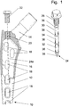
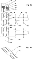
- FIG. 1 shows, on the left, partially in section, a femoral head prosthesis 10.
- This prosthesis has a body in the form of a hollow shaft 12 which at the upper end merges into an integral neck 14 which serves to hold a joint head (not shown).
- the shaft 12 forms a cavity 16, from which lateral openings 18 lead to the outside.
- a threaded hole 20 which serves to fill the shaft and to insert an extraction tool. In the known case, it is closed with an impact screw 22.
- the cavity 16 is usually filled with cancellous bone into which the bone tissue surrounding the implanted shaft is to grow.
- the prosthesis 10 is known.
- the screw 22 is replaced by an electrifying device which turns the prosthesis into an electrical prosthesis in the sense explained at the beginning.
- the device 24 shown on the right in FIG. 1, for example, whose construction essentially corresponds to that of the device described below. 2 may have a head 26 with an external or internal hexagon, a flange and a thread that fits into the threaded hole 20.
- a rod-like shaft 28 adjoins the head and contains a pick-up coil (46 in FIG. 2) which is electrically coupled to two tubular electrodes 30, 32 which are spaced in the longitudinal direction of the shaft and surround the shaft.
- An electrically insulating section 34 is located between the electrodes 30, 32.
- the shaft 28 is also surrounded by a plurality of insulating ring-shaped spacers 36 and runs out into a tip 38 designed as a mandrel or drill.
- the electrifying device 24 is used instead of the screw 22, as indicated by a dash-dotted line 24a, so that the shaft 28 extends into the cavity 16 in the region of the openings 18.
- FIG. 2 shows in longitudinal section a somewhat modified electrification device 24a for a prosthesis according to the device 24 of FIG. 1.
- the head 26a which is made of titanium, has an internal thread 40 at the lower end, into which an upper end 42, formed as an external thread, of the shaft 28a is screwed, which has a body 44 made of biocompatible plastic, such as PTFE.
- the body 44 encloses a pick-up coil 46, the winding of which surrounds a magnetic core 48, and carries on the outside two tubular electrodes 30a, 32a spaced apart in the longitudinal direction of the shaft 28a, between which there is an insulating web 50 serving as a spacer.
- the rounded tip 38a of the body 44 is thickened and forms a further spacer.
- the section of the shaft 28a adjoining the external thread forms a predetermined breaking point in the form of a constriction 33 or the like, which makes it possible to be able to remove the head 26a and to screw in an extraction tool without the possibly ingrown shaft 28a of the electrifying device being removed from the prosthesis must become.
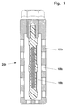
- Fig. 3 shows a schematic diagram of a device according to the invention.
- the device acc. 3 has a tubular body 12b, which forms a cavity 16b and has lateral openings 18b.
- One end of the body 12b has an end wall with openings, and an electrifying device 24b of the type explained with reference to FIG. 2 is screwed into the other end.
- an electrifying device 24b of the type explained with reference to FIG. 2 is screwed into the other end.
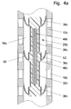
- Fig. 4a shows an embodiment of the present device, which z. B. for permanently implanted tubular osteosynthesis elements or endoprostheses, such as joint prosthesis shafts and intramedullary nails.
- Such an implant has a tubular body 12c which encloses a cavity 16c and has lateral openings 18c.
- An electrifying device 24c which essentially corresponds to that of FIG. 2, is inserted into the cavity 16c.
- Corresponding parts are identified by the same reference numerals, to which a "c" is added. However, it has no screw head and is held at a distance from the inner wall of the body 12c by annular spacers 36c, which have laterally projecting spring clips 52.
- the function of the device acc. 4a corresponds to that of FIG. 1.
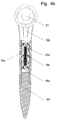
- FIG. 4b shows an arm joint prosthesis with a tubular shaft 12c in which an electrifying device 24c is inserted, as was described with reference to FIG. 4a.
- a joint head 51 At one end of the shaft 12c there is a joint head 51, the other end has been closed by inserting the electrifying device 24c by means of a pressed-in (or screwed-in) plug 53.
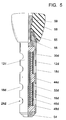
- FIG. 5 shows a device 24d according to the invention in the form of a dental implant. It has a tubular jacket or body 12d made of tissue-compatible metal, such as titanium, which forms a cavity 16d, has lateral openings 18d and is closed at the bottom by a pressed-in stopper 54. The other end of the body 16d forms a stable conical prosthesis carrier 55 with an internal thread 56. An artificial tooth 58 is fastened on the prosthesis carrier 55 with a screw 59 screwed into the internal thread.
- a device 24d of the type shown in FIG. 2 with a plastic shaft 44d which contains a pick-up coil 46d with a magnetic core 48d and carries electrodes 30d, 32d.
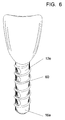
- FIG. 6 shows another embodiment of a dental implant. It corresponds to that of FIG. 5 with the exception that the Body 12e forms a thread 60 on the outside, with which body 16e can be screwed into the jawbone.
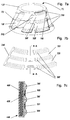
- FIG. 7a shows a known acetabular endoprosthesis 70, which according to the invention is provided with an electrifying device 24f shown in more detail in FIGS. 7b and 7c.
- the endoprosthesis 70 is double-walled and forms an annular, essentially frustoconical cavity 16f.
- the outer wall has oblique openings 18f and projections 72 which form a thread for screwing into the hip bone.
- the electrifying device 24f has the shape of a flexible band which is circular sector-shaped in accordance with the shape of the cavity 16f and which can be introduced into the cavity 16f through one of the openings 18f. It contains a strip-shaped magnetic core 48f which is surrounded by the winding of a pickup coil 46f.
- the magnetic core and coil are embedded in a body 44f made of a flexible, biocompatible material such as PTFE.
- the body carries on its one side, in the inserted state facing the openings, two strip-shaped electrodes 30f, 32f, which are coupled to the ends of the pick-up coil 46f, and forms three strip-shaped spacers 36f on the outer edges and between the electrodes 30f, 32f.
- the pick-up coil 46g in the electrifying device for the acetabular cup prosthesis can also be arranged at one end of a band-shaped, flexible body 44g which then only serves as a carrier for the electrodes 30g, 32g and the spacers 36g .
- the pick-up coil 46g encased in biocompatible material fits into an oblique opening 18g.
- the sheath of the pick-up coil 46g is provided at its ends with projecting tabs 74 so that the sheathed pick-up spool 46g can be pressed into the opening in question without falling through into the cavity 16g.
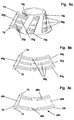
- the strip-shaped body 12h carries only a single electrode 30h and two strip-shaped spacers 36h arranged on both sides thereof.
- the second electrode is formed by the metallic socket prosthesis, which is contacted via at least one contact piece 76 coupled to the second end of the pick-up coil 46h.
- the contact piece 76 is located at one end of the casing of the pick-up coil 46h.
- FIGS. 8d and 8e show a further embodiment of an electrifying device for a prosthetic socket of the type shown in FIG. 8a.
- the device 24k has a thin, band-shaped carrier 44k which, to simplify the drawing, is straight and not, as in FIGS. 8b and 8c is shown curved.
- the carrier 44k has two punched, slot-shaped holes 80 at one end, which form a web 82.
- a pick-up coil 46k is inserted through the holes 80.
- the carrier 44k also has two rows of pairs of holes 84 in its longitudinal direction, through which strip-shaped electrodes 30k, 32k are threaded.
- the carrier 44k has a plurality of integral tabs 86 with an arrow-shaped end 90 on one longitudinal edge.
- the tabs 86 are bent backwards at the dash-dotted lines 92a, 92b, 92c and their ends 90 are inserted through elongated holes 88.
- An end piece (end flap) 93 of the carrier 44k is folded forward on the line 92d shown in broken lines before the end of the adjacent flap 86 is inserted through the associated elongated hole 88.
- the distance between the fold lines 92a and 92b corresponds essentially to the width of the band-shaped carrier 44k.
- the distance between the fold lines 92b and 92c is somewhat larger than the width of the carrier 44k, so that the relevant piece 86a (FIG. 8e) of the tab 86 bulges and acts as a spacer.
- the device here has a body 12i in the form of a flat bag made of reticulated, tissue-compatible, possibly resorbable material, which naturally has openings (meshes) and can be brought into a shape adapted to the desired use.
- the net-shaped body 12i encloses a space 16i in which there is a flat, flexible electrifying device 24i, which contains a flat, flexible pick-up coil 46i with a biocompatible covering and analogously to that according to FIG. 8b and 8c can be formed.
- the covering expediently has electrodes 30i, 32i and spacers 36i on both sides and its shape is adapted to that of the implant mesh bag. If the net-shaped body of such a device consists entirely or partially of an electrically conductive material, see DE-A-30 03 758 mentioned at the outset, the electrodes 30i, 32i on the casing of the pick-up coil 46i can all be connected to one connection of the pick-up coil 46i be, while the bag-shaped body 12i is connected as a counter electrode to the other terminal of the pick-up coil 46i.
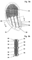
- the dental implant has a hollow, implantable shaft 102 made of an electrically conductive, biocompatible material, e.g. A metal such as titanium or a cobalt-chromium alloy.
- the shaft forms a cavity 104 which has a number of windows or openings 106 in the lower part.
- the outside of the shaft is coated with a coating 108 of hydroxyapatite.
- the lower end can be rounded or provided with a perforated, dome-shaped cap 110.
- the shaft 102 has an annular shoulder above the openings 106, which serves as a seat for an annular disk 112.
- the annular disk 112 forms a holder for an electrode 114, which has a thinner lower rod-shaped part 114a and a thicker upper part 114b resting on the annular disk with an internal thread 114c.
- the gap between the thicker part 114b and the opposite inner wall of the shaft is with a solid insulating material 116, e.g. B. synthetic resin or cement.
- a thread 118 or are otherwise profiled In order to ensure a firm connection, the outside of the thicker electrode part 114b and the opposite part of the inner wall of the shaft are provided with a thread 118 or are otherwise profiled.
- the upper end 102a of the shaft 102 is conical and forms a seat for an attached, separate pick-up coil unit 120.
- This has a plastic body 122 which surrounds a multi-layer pick-up coil 124, in which a hollow cylindrical soft iron magnetic core 126 is arranged.
- a terminal 124a of the pickup coil 124 is connected to a truncated cone-shaped contact piece 128 which is embedded in the lower end of the plastic body 122. It has an annular bead 130 at the lower end, which in the assembled state engages in an annular groove 131 of the shaft 102 and thereby makes contact with the upper end 102a of the shaft 102.
- the other terminal 120b of the pick-up coil 124 is connected to a funnel-shaped metal sleeve 134 which is embedded in the upper end of the plastic body 122.
- the plastic body On the outside, the plastic body has an external thread 138 for screwing on an artificial tooth.
- the artificial tooth is fixed on the unit 120 by means of a screw, not shown, analogous to the screw 59 in FIG. 5.
- the screw extends through the channel 135 and is screwed into the internal thread 114c, so that in addition to the mechanical connection of the artificial tooth, the unit 120 and the shaft 102, it also creates an electrical connection between the connection 124 and the electrode 114.
- the cavity 104 is used, as in the previous examples, to accommodate cancellous bone and the like. the like
- the body of the present device if it consists entirely or partially of an electrically conductive material, can serve as a second or counterelectrode, which then forms a type of coaxial structure with the internal electrode or electrodes forms and generates a current flowing essentially from the inside out.
- FIG. 11 shows a pickup coil unit 120a similar to the unit 120 according to FIG. 10.
- a threaded sleeve 140 with a connecting bridge 142 is fastened on the external thread of the plastic body 122a.
- the implant 100 shown in FIG. 10 can also be used with a spatially separate, independently implantable pickup coil, e.g. B. for stiffening two lumbar vertebrae 150, as shown in Fig. 12.
- the electrodes of unit 100 are powered by a remote sensor coil 124x or other implantable power source, e.g. B. an AC generator 124y, which is coupled to the shaft 120 or the electrode 114 (FIG. 10) via flexible, insulated lines 152 and a connection cap 154 shown in more detail in FIG. 13.
- connection cap 154 contains a funnel-shaped contact piece 128a corresponding to the contact piece 128 in FIG. 10, and a second funnel-shaped contact piece 134b. The contact pieces are separated by an insulating body 122a.
- the connection cap is connected to the unit 120 by a screw, not shown, as was explained with respect to the unit 120 with reference to FIG. 10.
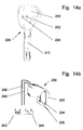
- FIG. 14a shows a dental implant 200 which contains an implantable first part in the form of a shaft 210 and a second part in the form of an artificial tooth 220 which is still accessible from the outside when the shaft is implanted.
- the structure of the shaft 210 can correspond to that according to FIG. 10, that is to say it has a hollow body with an electrically conductive surface and openings and at least one internal electrode.
- the implant 200 does not contain a pick-up coil or other voltage source, rather the externally accessible second part, i.e. here the screwed-on artificial tooth 220, has a connection device, not shown in FIG. 14a, of the type explained in connection with FIG. 13, the current supply lines of which are shown in FIG funnel-shaped contact pieces 222, 224 end at a cosmetically acceptable location, e.g. B. the back of the artificial tooth 220 are embedded in its surface.
- the electrodes (shaft body, inner electrode) of the implant are supplied with power with the aid of a clamp 230 shown in FIG. 14b, which contains a bracket 232 made of non-conductive material, such as plastic.
- a bracket 232 made of non-conductive material, such as plastic.
- two conical contact pieces 234, 236 are attached, which fit into the contact pieces 222, 224 and can be coupled via flexible lines 238, 240 to a source for a low-frequency AC voltage, for. B. a secondary or pickup coil 242 or a function generator 244 or other AC voltage source.
- the voltage source is external, completely separate from the implant and is only temporarily connected to the implant.
- connections for the external power source can also be arranged at other locations, e.g. B. on the shaft.
- the electrodes can also be coupled to an internal pick-up coil.
- a separate, implantable or external AC voltage source can be used instead of the pickup coil 46i - analogously to FIGS. 12, 14a, 14b.
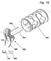
- Fig. 15 shows a device similar to Figs. 12 and 13. It contains a perforated cylindrical body made of titanium and a sealing cap 302 made of PTFE. The cap holds two axially extending pin-like electrodes 304, 306 with pointed ends that are connected to flexible, insulated leads 308, 310 for connecting the electrodes to an implanted pickup coil 342 or other AC source 344.
- the open end of the body is closed with the sealing cap 302, whereby the electrodes penetrate into the cancellous bone in the body.
- 16a shows the tibia part of the knee joint prosthesis known from the journal OSTEOLOGIE (l. C.). It has a semicircular body 402, on the underside of which four cylindrical rings 404 are attached. The body is secured in the tibia head by expansion sleeves or dowels 410 (FIGS. 16b and 16c) which are inserted through the rings 404.
- the dowel 410 shown in FIGS. 16b and 16c contains a perforated, cylindrical sleeve 412, which has axial slots at the ends.
- the ends can be slightly flared, as shown in Fig. 16c.
- the dowel also includes front and rear, slightly tapered end pieces 416 and 418, respectively, which can be pushed into the ends of the sleeve 412 by means of a screw 420 and then spread the slotted ends.
- a device 422 for stimulating tissue growth is arranged in the sleeve 412.
- the device 422 contains a pick-up coil 426 which is wound on a tubular magnetic core. The ends of coil 426 are coupled to annular electrodes 430, 432. A space remains between the electrodes 430, 432 and the inner wall of the sleeve 412, into which — stimulated by the electric field or the electric current between the electrodes — tissue can grow.
- the dowel 410 can also serve as a prosthesis socket.
- B. can be designed as a holder for a femoral head.
- electrodes in the form of halves or quarters etc. of a cylinder divided in the longitudinal direction can also be used.
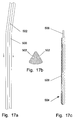
- FIG. 17a shows a part of an intramedullary nail 500 which, as the cross section in FIG. 17b shows, has longitudinal grooves 502 which are somewhat narrowed at their mouth.
- a device 504 is impressed or inserted into the longitudinal grooves 502.
- the device 504 includes a wire-shaped electrode 506 which is surrounded at a distance by a perforated tube or a tube 508 made of coarse-pored sintered material.
- the tube can be made of PTFE and the perforations can be made using a laser.
- the intramedullary nail 500 and the electrode 506 are connected to a pick-up coil (not shown) so that an electric field is created between the electrode and the intramedullary nail 500, which promotes tissue growth.
- tissue can grow through the slot-shaped opening of the groove into the space formed by the perforations or pores between the inner wall of the groove of the intramedullary nail and the internal electrode.
- two or more devices 504 can be provided in a corresponding number of grooves and the low-frequency alternating voltage can be applied between the electrodes 506 of these devices 504.
- the device 504 can also be used with other implants, e.g. B. in a femoral head prosthesis, the shaft is provided with one or more grooves or an acetabular cup prosthesis, as shown in FIGS. 18a and 18b.
- the acetabular cup prosthesis shown there contains a dome-shaped body 600 made of titanium or another tissue-compatible metal. On the outside, the body 600 has a number of annular grooves 602 with slot-shaped openings corresponding to the grooves 502 in FIG. 17b, on the inside it is lined with a shell 604 made of PTFE.
- Several eyes 606 are provided on the edge, which form holes for fastening the prosthesis to the hip bone.
- the edge contains a groove 608 for a pick-up coil, not shown.
- the groove 608 communicates through a hole with a meridional groove 610 that intersects the grooves 602.
- Devices 504 of the type shown in FIG. 17c are introduced into the grooves 602, the electrodes 506 of which are connected to the pickup coil via connecting lines which run in the groove 610.
- the holes of the insulating tube of device 504 form cavities from the surface of the electrode to the opening of the Lead groove.
- the electrodes in the grooves 602 can alternately be connected to opposite-pole connections of the pick-up coil, or else all to the one connection, the body 600 then being connected as a counter-electrode.
- the body can also have one or more spiral grooves analogous to a single or multiple thread for corresponding devices 506.
- FIG. 19 shows an electrical dowel similar to that according to FIG. 16b. Corresponding parts are therefore designated by the same reference numerals, to which an " a " is added, and the explanation is restricted to the differences.
- the device 410a of the dowel according to FIG. 19 contains only a single tubular electrode 430a which is coupled to a first connection of a pickup coil 411.
- the pick-up coil 411 sits on a tubular magnetic core 413, both of which are enclosed by the tubular body of the device 410a, which is made of PTFE and sits in an annular groove on the rear end face of the end piece 410a.
- the second connection of the pickup coil is electrically connected via a contacting device 415 to the metal end piece 416a, which together with the tubular, perforated metal part 412a and the metal piece 418a serves as a counter electrode.
- the dowel according to FIG. 19 corresponds to that according to FIG. 16b
Landscapes
- Health & Medical Sciences (AREA)
- Orthopedic Medicine & Surgery (AREA)
- Life Sciences & Earth Sciences (AREA)
- Engineering & Computer Science (AREA)
- Biomedical Technology (AREA)
- Veterinary Medicine (AREA)
- Animal Behavior & Ethology (AREA)
- General Health & Medical Sciences (AREA)
- Public Health (AREA)
- Oral & Maxillofacial Surgery (AREA)
- Heart & Thoracic Surgery (AREA)
- Cardiology (AREA)
- Vascular Medicine (AREA)
- Transplantation (AREA)
- Neurology (AREA)
- Nuclear Medicine, Radiotherapy & Molecular Imaging (AREA)
- Surgery (AREA)
- Radiology & Medical Imaging (AREA)
- Dentistry (AREA)
- Epidemiology (AREA)
- Developmental Biology & Embryology (AREA)
- Cell Biology (AREA)
- Molecular Biology (AREA)
- Medical Informatics (AREA)
- Physical Education & Sports Medicine (AREA)
- Prostheses (AREA)
- Electrotherapy Devices (AREA)
- Materials For Medical Uses (AREA)
Abstract
Description
Die vorliegende Erfindung betrifft eine implantierbare Vorrichtung mit einem ihrer Funktion entsprechenden, aus biokompatiblem Material bestehenden Körper, welcher einen inneren Hohlraum bildet, mindestens eine Durchbrechung aufweist und mit Elektroden versehen ist, denen eine niederfrequente Wechselspannung zuführbar ist.The present invention relates to an implantable device with a body corresponding to its function, consisting of biocompatible material, which forms an internal cavity, has at least one opening and is provided with electrodes to which a low-frequency AC voltage can be supplied.
In den menschlichen Körper implantierbare Vorrichtungen der hier interessierenden Art, wie Gelenkprothesen, Zahnprothesen, Knorpelsubstrate, z. B. zum Aufbau von Ohrgewebe, u. a. m. haben einen ihrer medizinischen Funktion entsprechenden, lasttragenden oder formgebenden Körper aus einem biokompatiblen Material, wie Metall, Kunststoff oder Keramik.Devices of the type of interest here implantable in the human body, such as joint prostheses, dentures, cartilage substrates, e.g. B. to build up ear tissue, u. a. m. have a load-bearing or shaping body made of a biocompatible material, such as metal, plastic or ceramic, which corresponds to their medical function.
Aus der Zeitschrift OSTEOLOGIE, Band 5, Heft 2, 1996, S. 87 sind Gelenkprothesen aus Titan bekannt, die durch Spreizhülsen am Knochen befestigt werden.Joint prostheses made of titanium are known from the magazine OSTEOLOGIE, Volume 5, Issue 2, 1996, p. 87 and are attached to the bone by expansion sleeves.
Aus den "Orthopedic Product News" May/June 1995, S. 8 sind Implantate zur Stabilisierung von Rückenwirbeln bekannt.From the "Orthopedic Product News" May / June 1995, p. 8, implants for stabilizing vertebrae are known.
Es sind ferner implantierbare Vorrichtung bekannt, deren Körper einen Hohlraum bildet und offene Durchbrechungen aufweist, die vom Hohlraum nach außen führen. Der Hohlraum dient zur Aufnahme von Spongiosa oder anderem bioaktiven Material, das das Einwachsen des die implantierte Vorrichtung umgebenden Gewebes in die Durchbrechungen fördern soll. Ein typisches Beispiel einer solchen Vorrichtung ist die von Prof. Täger entwickelte Hüftgelenkprothese. Der Hüftgelenkkopfteil dieser Prothese hat einen hohlen, mit seitlichen Durchbrechungen versehenen Schaft. Der Gelenkpfannenteil ist doppelwandig und bildet einen ringförmigen Hohlraum. Die Außenwand bildet eine Art von Außengewinde und hat eine Reihe schräger, schlitzförmiger Durchbrechungen.Implantable devices are also known, the body of which forms a cavity and has open openings which lead from the cavity to the outside. The cavity serves to accommodate cancellous bone or other bioactive material which is intended to promote the ingrowth of the tissue surrounding the implanted device into the openings. A typical example of such a device is the hip joint prosthesis developed by Prof. Täger. The hip joint head part of this prosthesis has a hollow shaft with side openings. The joint socket part is double-walled and forms an annular cavity. The outer wall forms a kind of external thread and has a series of oblique, slit-shaped openings.
Es ist auch bekannt, daß das Wachstum von Gewebe, insbesondere Knochengewebe, des menschlichen Körpers durch einen niederfrequenten Wechselstrom gefördert werden kann. Vorrichtungen ("Elektro-Implantate"), die von dieser Erkenntnis Gebrauch machen, enthalten eine implantierbare Aufnehmer- oder Sekundärspule, die mit Gewebeelektroden verbunden oder gekoppelt ist und in der durch eine externe Primärspule eine niederfrequente Wechselspannung induzierbar ist. Frequenzen unter 20 Hz, vorzugsweise unter 15 oder 10 Hz haben sich bewährt, die Kurvenform soll sinus- oder pulswellenförmig sein. Dieses Prinzip findet auch bei der vorliegenden Erfindung Anwendung.It is also known that the growth of tissue, particularly bone tissue, of the human body can be promoted by a low frequency alternating current. Devices ("electrical implants") which make use of this knowledge contain an implantable pickup or secondary coil which is connected or coupled to tissue electrodes and in which a low-frequency alternating voltage can be induced by an external primary coil. Frequencies below 20 Hz, preferably below 15 or 10 Hz, have proven their worth; the curve shape should be sinusoidal or pulse wave-shaped. This principle also applies to the present invention.
Eine aus der DE-C-23 15 517 bekannte Elektro-Hüftkopfprothese hat einen Schaft mit einem Hohlraum, in dem eine Aufnehmerspule untergebracht ist. Die Aufnehmerspule ist mit Elektroden gekoppelt, die außen auf dem Schaft angebracht sind.An electric femoral head prosthesis known from DE-C-23 15 517 has a shaft with a cavity in which a pick-up coil is accommodated. The pick-up coil is coupled to electrodes which are attached to the outside of the shaft.
Eine Elektro-Zahnprothese in Form eines Kunstzahnes aus Keramik, der eine Aufnehmerspule enthält und auf seiner Außenfläche Elektroden trägt, ist aus der DE-C-26 11 744 bekannt.An electric dental prosthesis in the form of an artificial tooth made of ceramic, which contains a pick-up coil and carries electrodes on its outer surface, is known from DE-C-26 11 744.
Eine Vorrichtung zur Vitalerhaltung von Knochengewebe mit einer Aufnehmerspule und zwei mit dieser verbundenen Elektoden, die in einen kegelstumpfmantelförmigen netzartigen Träger integriert sind, ist aus der DE-A-30 03 758 bekannt.A device for maintaining the vitality of bone tissue with a pick-up coil and two electrodes connected to it, which are integrated in a frustoconical mesh-like support, is known from DE-A-30 03 758.
Ein Marknagel, der eine Aufnehmerspule enthält und auf der Außenseite zwei Gewebeelektroden trägt, ist aus der US-A-38 20 534 bekannt.An intramedullary nail which contains a pick-up coil and carries two tissue electrodes on the outside is known from US-A-38 20 534.
Aus der DE-A-34 14 992 ist ein künstlicher Zahn bekannt, der einen Schaft aus gewebeverträglichem Metall hat. Der Schaft hat eine rechteckige, diametrale Durchbrechung, an deren Innenwand eine Elektrode angeordnet ist. Zwischen den Schaft und die Elektrode kann eine niederfrequente Wechselspannung angelegt werden, um das Einwachsen des Schaftes in den Kiefernknochen zu fördern. Der das Gewebewachstum fördernde Strom fließt im wesentlichen von den Außenrändern der in der Durchbrechung angeordneten Elektrode zu den die Durchbrechung begrenzenden Rändern des Schaftes, nicht jedoch innerhalb der Durchbrechung, so daß das Gewebe nicht veranlaßt wird in die Durchbrechung hinein zu wachsen.From DE-A-34 14 992 an artificial tooth is known which has a shaft made of metal compatible with tissue. The shaft has a rectangular, diametrical opening, on the inner wall of which an electrode is arranged. A low-frequency AC voltage can be applied between the shaft and the electrode in order to promote the ingrowth of the shaft in the jawbone. The current that promotes tissue growth essentially flows from the outer edges of the opening arranged electrode to the edges of the shaft delimiting the opening, but not within the opening, so that the tissue is not caused to grow into the opening.
Der vorliegenden Erfindung liegt die Aufgabe zugrunde eine implantierbare Vorrichtung der eingangs genannten Art so auszugestalten, daß das Einwachsen des äußeren Gewebes in den Hohlraum oder die Hohlräume der Vorrichtung gefördert wird, also eine Vorrichtung, die einen ihrer medizinischen Funktion entsprechend gestalteten, lasttragenden oder formgebenden Körper aus biokompatiblen Material hat, der mindestens einen inneren Hohlraum bildet, in den, wenn gewünscht, Spongiosa oder anderes biologisch wirksames Material eingebracht werden kann, wobei vom Hohlraum Durchbrechungen oder Öffnungen nach Außen führen, durch die das Gewebe, das die implantierte Vorrichtung umgibt, in den Hohlraum hinein wachsen soll.The object of the present invention is to design an implantable device of the type mentioned at the outset in such a way that the ingrowth of the outer tissue into the cavity or the cavities of the device is promoted, that is to say a device which has a load-bearing or shaping body designed in accordance with its medical function made of biocompatible material which forms at least one internal cavity into which, if desired, cancellous bone or other biologically active material can be introduced, openings or openings leading from the cavity to the outside through which the tissue which surrounds the implanted device enters the cavity should grow into.
Diese Aufgabe wird erfindungsgemäß dadurch gelöst, daß die Vorrichtung in bekannter Weise mit einer Aufnehmerspule oder anderen Stromzuführungsvorrichtung versehen ist, die mit mindestens zwei Elektroden gekoppelt ist, und daß mindestens eine der Elektroden innerhalb des Hohlraumes so angeordnet ist, daß sie von der inneren Begrenzung des Hohlraumes mit Abstand umgeben wird.This object is achieved in that the device is provided in a known manner with a pickup coil or other power supply device which is coupled to at least two electrodes, and that at least one of the electrodes is arranged within the cavity so that it is from the inner boundary of the Cavity is surrounded by a distance.
Der Bereich des Hohlraumes zwischen mindestens einer Durchbrechung, die im implantierten Zustand der Vorrichtung zum umgebenden, zum Einwachsen zu veranlassenden Gewebe hin weist, und der innerhalb des Hohlraums angeordneten Elektrode ist ganz oder teilweise frei von Teilen der Vorrichtung, so daß er biologisch aktives Material und/oder einwachsendes Gewebe aufnehmen kann. Wenn den Elektroden eine niederfrequente Wechselspannung zugeführt wird, entsteht ein von innen nach außen gerichtetes niederfrequentes elektrisches Wechselfeld und fließt ein niederfrequenter Wechselstrom im Inneren des Hohlraumes, die das Einwachsen des äußeren Gewebes durch die Durchbrechungen oder Löcher in den Hohlraum fördern und dadurch das Implantat im umgebenden Gewebe fest verankern.The region of the cavity between at least one opening, which points in the implanted state of the device to the surrounding tissue to be caused to ingrowth, and the electrode arranged within the cavity is completely or partially free of parts of the device, so that it is biologically active material and / or can take in growing tissue. When a low-frequency alternating voltage is applied to the electrodes, a low-frequency alternating electric field is directed from the inside to the outside and a low-frequency alternating current flows inside the cavity, which promote the ingrowth of the outer tissue through the openings or holes in the cavity and thereby the implant in the surrounding area Anchor tissue firmly.
Wenn hier von Durchbrechungen oder Löchern gesprochen wird, sind makroskopische Löcher gemeint, nicht mikroskopische Poren, wie sie für feinporige Sintermaterialien typisch sind. Bei starren Implantaten werden die Durchbrechungen im allgemeinen Querschnittsflächen im Bereich von einigen bis mehreren 10mm2 und mehr haben. Bei grobporigen, gesinterten oder netzartigen Strukturen haben die Durchbrechungen im allgemeinen Größen im Bereich von einigen Zehntel mm2 bis zu einigen mm2.When we talk about openings or holes, we mean macroscopic holes, not microscopic pores, as are typical for fine-pored sintered materials. In the case of rigid implants, the openings generally have cross-sectional areas in the range from a few to several 10 mm 2 and more. In the case of coarse-pored, sintered or mesh-like structures, the openings generally have sizes in the range from a few tenths of a mm 2 to a few mm 2 .
Der lasttragende oder formgebende Körper kann die verschiedenste Gestalt haben, z. B. die einer Hüftgelenkkopfprothese, einer Hüftgelenkpfannenprothese oder anderer Gelenkprothesen, einer Verankerung für eine Zahnprothese, eines Lendenwirbelsäulen-Plugs oder einer formgebenden netzartigen Struktur für den Aufbau einer Ohrmuschel, Nase u. s. w.The load-bearing or shaping body can have a wide variety of shapes, e.g. B. a hip joint head prosthesis, an acetabular cup prosthesis or other joint prosthesis, an anchor for a dental prosthesis, a lumbar spine plug or a shaping net-like structure for the construction of an auricle, nose and. s. w.
Wenn der durchbrochene Körper elektrisch leitfähig und als Gegenelektrode zu der in seinem Innenraum isoliert von ihm angeordneten Innenelektrode geschaltet ist, kann es vorteilhaft sein, zwischen die Elektroden eine niederfrequente Wechselspannung zu legen, der eine Gleichstromkomponente solcher Polarität überlagert ist, daß die äußere Elektrode die Kathode bildet. Die Größe der Gleichspannungskomponente kann z. B. 20%, ggf. bis zu 50% der gewöhnlich bis zu etwa 700 mV/eff betragenden Amplitude der Wechselspannung ausmachen. Bei Verwendung einer implantierten Aufnehmerspule als Spannungsquelle kann die Gleichspannungskomponente dadurch erzeugt werden, daß man in die Leitung zwischen einer der Elektroden und dem zugehörigen Anschluß der Aufnehmerspule eine Diode schaltet, der ein Widerstand parallel liegt.If the perforated body is electrically conductive and is connected as a counter electrode to the inner electrode which is insulated from it in its interior, it can be advantageous to place a low-frequency AC voltage between the electrodes, which is superimposed on a DC component of such polarity that the outer electrode overlies the cathode forms. The size of the DC component can e.g. B. 20%, possibly up to 50% of the usually up to about 700 mV / eff amplitude of the AC voltage. When using an implanted pick-up coil as a voltage source, the DC voltage component can be generated by switching a diode in the line between one of the electrodes and the associated connection of the pick-up coil, which has a resistor in parallel.
In folgenden wird die Erfindung anhand von Ausführungsbeispielen unter Bezugnahme auf die Zeichnungen näher erläutert. Die Abbildungen sind zum Teil stark vergrößert.The invention is explained in more detail below on the basis of exemplary embodiments with reference to the drawings. Some of the images are greatly enlarged.
Es zeigen:
- Fig. 1
- eine Schnittansicht einer bekannten Hüftgelenkopfprothese und eine für diese bestimmte Elektrifizier- oder Zusatzvorrichtung gemäß der Erfindung;
- Fig. 2
- eine etwas abgewandelte Ausführungsform der Elektrifiziervorrichtung gemäß Fig. 1, die eine bevorzugten inneren Aufbau solcher Vorrichtungen erkennen läßt,
- Fig. 3
- eine Prinzipdarstellung einer weiteren Ausführungsform der Erfindung,
- Fig. 4a
- eine Ausführungsform der Erfindung, die sich insbesondere für ein dauernd implantiertes Osteosyntheseelement eignet,
- Fig. 4b
- eine Armgelenkprothese entsprechend Fig. 4a,
- Fig. 5 und 6
- zwei Ausführungsbeispiele in Form von Dentalimplantaten,
- Fig. 7a
- eine teilweise geschnittene, perspektivische Ansicht einer Hüftgelenkpfannenprothese gemäß der Erfindung,
- Fig. 7b
- eine Draufsicht einer Elektrifiziervorrichtung der Prothese gemäß Fig. 7a,
- Fig. 7c
- einen etwas vergrößerten Querschnitt in einer Ebene A - A der Fig. 7b,
- Fig. 8a
- eine vereinfachte Darstellung einer anderen Ausführungsform einer Hüftgelenkpfannenprothese,
- Fig. 8b
- eine Darstellung der Elektrifiziervorrichtung der Prothese gemäß Fig. 8a,
- Fig. 8c
- eine Abwandlung der Vorrichtung gemäß Fig. 8b,
- Fig 8d
- eine weitere Abwandlung der Vorrichtung gemäß Fig. 8b,
- Fig. 9a
- eine zur Förderung des Aufbaus von Knorpel- und Bindegewebe dienende Ausführungsform,
- Fig. 9b
- eine etwas vergrößerte Schnittansicht der Vorrichtung gemäß Fig 9a in einer Ebene B - B der Fig 9a,
- Fig. 10
- eine Schnittansicht eines weiteren Dentalimplantats,
- Fig. 11
- eine abgewandelte Aufnehmerspuleneinheit,
- Fig. 12
- eine zwischen zwei Lendenwirbeln implantierte Vorrichtung,
- Fig. 13
- eine Anschlußkappe für die Vorrichtung gemäß Fig. 12,
- Fig. 14a
- eine anderes Beispiel eines Dentalimplantats,
- Fig. 14b
- eine Zusatzvorrichtung zum Ankoppeln einer externen Spannungsquelle an das Dentalimplantat gem. Fig. 14a,
- Fig. 15
- eine weitere Vorrichtung der in Fig. 12 und 13 dargestellten Art,
- Fig.
16a und 16b - Teile einer Kniegelenkprothese,
- Fig. 16c
- einen Axialschnitt eines in Fig. 16b auseinandergezogen dargestellten Spreiz-Dübels,
- Fig. 17a und 17b
- eine Seitenansicht bzw. Schnittansicht eines Teiles eines Marknagels,
- Fig. 17c
- eine teilweise geschnittene Ansicht einer erfindungsgemäßen Vorrichtung für den Marknagel gemäß Fig 17a und 17b.
- Fig.
18a und 18b - eine geschnittene bzw. isometrische Darstellung einer Hüftgelenkschalenprothese, und
- Fig 19
- eine auseinandergezogene Darstellung eines Elektro-Dübels gemäß der Erfindung.
- Fig. 1
- a sectional view of a known hip joint prosthesis and a specific for this electrifying or additional device according to the invention;
- Fig. 2
- 1 shows a slightly modified embodiment of the electrifying device according to FIG. 1, which shows a preferred internal structure of such devices,
- Fig. 3
- a schematic diagram of another embodiment of the invention,
- Fig. 4a
- one embodiment of the invention which is particularly suitable for a permanently implanted osteosynthesis element,
- Fig. 4b
- an arm joint prosthesis according to FIG. 4a,
- 5 and 6
- two exemplary embodiments in the form of dental implants,
- Fig. 7a
- 3 shows a partially cut, perspective view of an acetabular cup prosthesis according to the invention,
- Fig. 7b
- 7a shows a top view of an electrification device of the prosthesis according to FIG.
- Fig. 7c
- a somewhat enlarged cross section in a plane A - A of Fig. 7b,
- Fig. 8a
- a simplified representation of another embodiment of an acetabular cup,
- Fig. 8b
- 2 shows a representation of the electrification device of the prosthesis according to FIG. 8a,
- Fig. 8c
- a modification of the device according to FIG. 8b,
- Fig 8d
- a further modification of the device according to FIG. 8b,
- Fig. 9a
- an embodiment serving to promote the building up of cartilage and connective tissue,
- Fig. 9b
- 9a shows a somewhat enlarged sectional view of the device according to FIG. 9a in a plane BB of FIG. 9a,
- Fig. 10
- 2 shows a sectional view of a further dental implant,
- Fig. 11
- a modified pick-up coil unit,
- Fig. 12
- a device implanted between two lumbar vertebrae,
- Fig. 13
- a connection cap for the device according to FIG. 12,
- 14a
- another example of a dental implant,
- 14b
- an additional device for coupling an external voltage source to the dental implant acc. 14a,
- Fig. 15
- another device of the type shown in FIGS. 12 and 13,
- 16a and 16b
- Parts of a prosthetic knee joint,
- 16c
- 16b shows an axial section of an expansion dowel shown pulled apart in FIG. 16b,
- 17a and 17b
- a side view or sectional view of a part of an intramedullary nail,
- Fig. 17c
- a partially sectioned view of a device according to the invention for the intramedullary nail according to FIGS. 17a and 17b.
- 18a and 18b
- a sectional or isometric view of a hip joint prosthesis, and
- Fig. 19
- an exploded view of an electrical dowel according to the invention.
Fig. 1 zeigt links, teilweise geschnitten, eine Hüftgelenkkopfprothese 10. Diese Prothese hat einen Körper in Form eines hohlen Schaftes 12, der am oberem Ende in einen integralen Hals 14 übergeht, der zur Halterung eines Gelenkkopfes (nicht dargestellt) dient. Der Schaft 12 bildet einen Hohlraum 16, von dem aus seitliche Durchbrechungen 18 nach außen führen. Am halsseitigen Ende des Hohlraumes 16 befindet sich ein Gewindeloch 20, das zum Auffüllen des Schaftes und zum Einsetzen eines Extraktionswerkzeugs dient, es wird im bekannten Fall mit einer Einschlag-Schraube 22 verschlossen. Der Hohlraum 16 wird gewöhnlich mit Spongiosa gefüllt, in die das den implantierten Schaft umgebende Knochengewebe hineinwachsen soll. Soweit beschrieben, ist die Prothese 10 bekannt.1 shows, on the left, partially in section, a
Gemäß der Erfindung wird die Schraube 22 durch eine Elektrifiziervorrichtung ersetzt, die die Prothese zu einer Elektroprothese im eingangs erläuterten Sinne macht. Die in Fig. 1 rechts beispielsweise dargestellte Vorrichtung 24, deren Konstruktion im wesentlichen der der im folgenden beschriebenen Vorrichtung gem. Fig. 2 entsprechen kann, hat einen Kopf 26 mit einem Außen- oder Innen-Sechskant, einem Flansch und einem in das Gewindeloch 20 passenden Gewinde. An den Kopf schließt sich ein stabartiger Schaft 28 an, der eine Aufnehmerspule (46 in Fig.2) enthält, die mit zwei in Längsrichtung des Schaftes beabstandeten, den Schaft umgebenden rohrförmigen Elektroden 30, 32 elektrisch gekoppelt ist. Zwischen den Elektroden 30, 32 befindet sich ein elektrisch isolierender Abschnitt 34. Der Schaft 28 ist ferner mit mehreren isolierenden ringförmigen Abstandshaltern 36 umgeben und läuft in eine als Dorn oder Bohrer ausgebildete Spitze 38 aus. Die Elektrifiziervorrichtung 24 wird anstelle der Schraube 22 eingesetzt, wie durch eine strichpunktierte Linie 24a angedeutet ist, sodaß sich der Schaft 28 im Bereich der Durchbrechungen 18 in den Hohlraum 16 erstreckt. Wenn die so ausgestaltete Prothese implantiert und der Hohlraum mit Spongiosa gefüllt ist und dann in der Aufnehmerspule mittels einer äußeren, mit einem niederfrequenten Wechselstrom gespeisten Spule eine niederfrequente Wechselspannung induziert wird, entsteht im Inneren des Hohlraumes 16 ein niederfrequentes elektrisches Wechselfeld und fließt in dem sich im Inneren des Hohlraumes 16 befindlichen Material ein niederfrequenter Wechselstrom, wodurch das Einwachsen des den Prothesenschaft 12 umgebenden Knochengewebes in die Durchbrechungen 18 gefördert und damit der Halt der Prothese gefestigt werden.According to the invention, the
Fig. 2 zeigt im Längsschnitt eine in Bezug auf die Vorrichtung 24 der Fig. 1 etwas abgewandelte Elektrifiziervorrichtung 24a für eine Prothese gem. Fig. 1. Der aus Titan bestehende Kopf 26a hat am unteren Ende ein Innengewinde 40, in das ein als Außengewinde ausgebildetes oberes Ende 42 des Schaftes 28a eingeschraubt ist, der einen aus biokompatiblen Kunststoff, wie PTFE, bestehenden Körper 44 hat. Der Körper 44 umschließt eine Aufnehmerspule 46, deren Wicklung einen Magnetkern 48 umgibt, und trägt außen zwei in Längsrichtung des Schaftes 28a beabstandete rohrförmige Elektroden 30a, 32a, zwischen denen sich ein als Abstandshalter dienender isolierender Steg 50 befindet. Die hier abgerundete Spitze 38a des Körpers 44 ist verdickt und bildet einen weiteren Abstandshalter. Der sich an das Außengewinde anschließende Abschnitt des Schaftes 28a bildet eine Sollbruchstelle in Form einer Einschnürung 33 oder dgl., die es ermöglicht, den Kopf 26a entfernen zu können und ein Extraktionswerkzeug einzuschrauben, ohne daß der gegebenenfalls eingewachsene Schaft 28a der Elektrifiziervorrichtung aus der Prothese entfernt werden muß.FIG. 2 shows in longitudinal section a somewhat modified
Fig. 3 zeigt eine Prinzipdarstellung einer erfindungsgemäßen Vorrichtung. Die Vorrichtung gem. Fig. 3 hat einen rohrförmig dargestellten Körper 12b, der einen Hohlraum 16b bildet und seitliche Durchbrechungen 18b aufweist. Das eine Ende des Körpers 12b weist eine Stirnwand mit Durchbrechungen auf, in das andere Ende ist eine Elektrifiziervorrichtung 24b der anhand von Fig. 2 erläuterten Art eingeschraubt. Hinsichtlich der Funktion der Vorrichtung gem. Fig. 3 gelten die unter Bezug auf Fig. 1 gemachten Ausführungen.Fig. 3 shows a schematic diagram of a device according to the invention. The device acc. 3 has a
Fig. 4a zeigt eine Ausführungsform der vorliegenden Vorrichtung, die sich z. B. für dauerhaft implantierte rohrförmige Osteosynthese-Elemente oder Endoprothesen, wie Gelenkprothesenschäfte und Marknägel, eignet. Ein solches Implantat hat einen rohrförmigen Körper 12c, der einen Hohlraum 16c umschließt und seitliche Durchbrechungen 18c hat. In den Hohlraum 16c ist eine Elektrifizier-Vorrichtung 24c eingeschoben, die im Wesentlichen der der Fig. 2 entspricht, entsprechende Teile sind mit den gleichen Bezugszahlen bezeichnet, denen ein "c" angefügt ist. Sie hat jedoch keinen Schraubenkopf und wird durch ringförmige Abstandshalter 36c, die seitlich vorspringende Federbügel 52 aufweisen, im Abstand von der Innenwand des Körpers 12c gehalten. Die Funktion der Vorrichtung gem. Fig. 4a entspicht der der Fig. 1.Fig. 4a shows an embodiment of the present device, which z. B. for permanently implanted tubular osteosynthesis elements or endoprostheses, such as joint prosthesis shafts and intramedullary nails. Such an implant has a
Fig. 4b zeigt eine Armgelenkprothese mit rohrförmigem Schaft 12c in den eine Elektrifiziervorrichtung 24c eingesetzt ist, wie sie anhand von Fig. 4a beschrieben wurde. Am einen Ende des Schaftes 12c befindet sich ein Gelenkkopf 51, das andere Ende ist nach dem Einsetzen der Elektrifiziervorrichtung 24c durch einen eingepreßten (oder eingeschraubten) Stopfen 53 verschlossen worden.FIG. 4b shows an arm joint prosthesis with a
Fig. 5 zeigt eine erfindungsgemäße Vorrichtung 24d in Form eines Zahnimplantats. Sie hat einen rohrförmigen Mantel oder Körper 12d aus gewebeverträglichem Metall, wie Titan, der einen Hohlraum 16d bildet, seitliche Durchbrechungen 18d aufweist und unten durch einen eingepreßten Stopfen 54 geschlossen ist. Das andere Ende des Körpers 16d bildet einen stabilen konischen Prothesenträger 55 mit einem Innengewinde 56. Auf dem Prothesenträger 55 ist ein Kunstzahn 58 mit einer in das Innengewinde eingeschraubten Schraube 59 befestigt. Im Hohlraum 16d befindet sich eine Vorrichtung 24d der in Fig. 2 dargestellten Art mit einem Kunststoffschaft 44d, der eine Aufnehmerspule 46d mit Magnetkern 48d enthält und Elektroden 30d, 32d trägt.5 shows a
Fig. 6 zeigt eine andere Ausführungsform eines Dentalimplantats. Es entspricht dem der Fig. 5 mit der Ausnahme, daß der Körper 12e außen ein Gewinde 60 bildet, mit dem der Körper 16e in den Kieferknochen eingeschraubt werden kann.6 shows another embodiment of a dental implant. It corresponds to that of FIG. 5 with the exception that the
Die Fig. 7a zeigt eine bekannte Hüftgelenkpfannen-Endoprothese 70, die erfindungsgemäß mit einer in den Fig. 7b und 7c genauer dargestellten Elektrifiziervorrichtung 24f versehen ist. Die Endoprothese 70 ist doppelwandig und bildet einen ringförmigen, im wesentlichen kegelstumpfmantelförmigen Hohlraum 16f. Die Außenwand hat schräge Durchbrechungen 18f und Vorsprünge 72, die ein Gewinde zum Einschrauben in den Hüftknochen bilden.FIG. 7a shows a known
Die Elektrifiziervorrichtung 24f hat, wie Fig. 7b und 7c zeigen, die Form eines flexiblen Bandes, das der Form des Hohlraumes 16f entsprechend kreisringsektorförmig ist und der durch eine der Durchbrechungen 18f in den Hohlraum 16f eingeführt werden kann. Sie enthält einen streifenförmigen Magnetkern 48f, der von der Wicklung einer Aufnehmerspule 46f umgeben ist. Magnetkern und Spule sind in einen Körper 44f aus einem flexiblen, biokompatiblen Material, wie PTFE, eingebettet. Der Körper trägt auf seiner einen, im eingesetzten Zustand den Durchbrechungen zugewandten Seite zwei streifenförmige Elektroden 30f, 32f, die mit den Enden der Aufnehmerspule 46f gekoppelt sind, und bildet an den Außenrändern und zwischen den Elektroden 30f, 32f drei leistenförmige Abstandshalter 36f.As shown in FIGS. 7b and 7c, the
Wie die Fig. 8a und 8b zeigen, kann die Aufnehmerspule 46g bei der Elektrifiziervorrichtung für die Hüftgelenkpfannen-Prothese auch am einen Ende eines bandförmigen, flexiblen Körpers 44g angeordnet sein, der dann nur als Träger für die Elektroden 30g, 32g und die Abstandshalter 36g dient. Die mit biokompatiblem Material umhüllte Aufnehmerspule 46g paßt in eine schräge Durchbrechung 18g. Die Umhüllung der Aufnehmerspule 46g ist an ihren Enden mit vorspringenden Laschen 74 versehen, so daß die umhüllte Aufnehmerspule 46g ohne in den Hohlraum 16g durchzufallen wie ein Stöpsel in die betreffende Durchbrechung eingedrückt werden kann.As FIGS. 8a and 8b show, the pick-up
Bei der in Fig. 8c dargestellten Abwandlung der Elektrifiziervorrichtung der Fig. 8b trägt der streifenförmige Körper 12h nur eine einzige Elektrode 30h und zwei beidseits von dieser angeordnete leistenförmige Abstandshalter 36h. Die zweite Elektrode wird durch die metallische Pfannenprothese gebildet, die über mindestens ein mit dem zweiten Ende der Aufnehmerspule 46h gekoppeltes Kontaktstück 76 kontaktiert ist. Das Kontaktstück 76 befindet sich am einen Ende der Umhüllung der Aufnehmerspule 46h.In the modification of the electrifying device of FIG. 8b shown in FIG. 8c, the strip-shaped
Die Figuren 8d und 8e zeigen eine weitere Ausführungsform einer Elektrifiziervorrichtung für eine Prothesenpfanne der in Fig. 8a dargestellten Art. Die Vorrichtung 24k hat einen dünnen, bandförmigen Träger 44k, der zur Vereinfachung der Zeichnung gerade und nicht, wie in den Fig. 8b und 8c gekrümmt dargestellt ist. Der Träger 44k hat am einen Ende zwei ausgestanzte, schlitzförmige Löcher 80, die einen Steg 82 bilden. Durch die Löcher 80 ist eine Aufnehmerspule 46k gesteckt. Der Träger 44k hat ferner in seiner Längsrichtung zwei Reihen von Lochpaaren 84, durch die streifenförmige Elektroden 30k, 32k gefädelt sind. Am einen Längsrand hat der Träger 44k mehrere integrale Laschen 86 mit pfeilförmigem Ende 90. Die Laschen 86 werden.an den strichpunktiert gezeichneten Linien 92a, 92b, 92c nach hinten geknickt und mit ihren Enden 90 durch Langlöcher 88 gesteckt. Ein Endstück (Abschlußlasche) 93 des Trägers 44k wird an den strichpunktiert gezeichneten Linie 92d nach vorne umgelegt, bevor das Ende der benachbarten Lasche 86 durch das zugehörige Langloch 88 gesteckt wird. Der Abstand zwischen den Knicklinien 92a und 92b entspricht im wesentlichen der Breite des bandförmigen Trägers 44k. Der Abstand zwischen den Knicklinien 92b und 92c ist jedoch etwas größer als die Breite des Trägers 44k, sodaß das betreffende Stück 86a (Fig. 8e) der Lasche 86 sich wölbt und als Abstandshalter wirkt.FIGS. 8d and 8e show a further embodiment of an electrifying device for a prosthetic socket of the type shown in FIG. 8a. The
Fig. 9a und 9b zeigen ein Ausführungsbeispiel der vorliegenden Vorrichtung, das zur Förderung des Aufbaus von Binde-, und Knorpelgewebes eines menschlichen Ohres dient. Die Vorrichtung hat hier einen Körper 12i in Form eines flachen Beutels aus netzförmigem gewebeverträglichen, ggf. resorbierbaren Material, das von Natur aus Durchbrechungen (Maschen) aufweist und in eine dem gewünschten Verwendungszweck angepaßte Form gebracht werden kann. Der netzförmige Körper 12i umschließt einen Raum 16i, in dem sich eine flache, flexible Elektrifiziervorrichtung 24i befindet, die eine flache, flexible Aufnehmerspule 46i mit einer biokompatiblen Umhüllung enthält und analog zu der gem. Fig. 8b und 8c ausgebildet sein kann. Die Umhüllung weist jedoch zweckmäßigerweise auf beiden Seiten Elektroden 30i, 32i und Abstandshalter 36i auf und ist in ihrer Form der des Implantatnetzbeutels angepaßt. Wenn der netzförmige Körper einer solchen Vorrichtung ganz oder teilweise aus einem elektrisch leitenden Material besteht, siehe die eingangs genannte DE-A-30 03 758, können die Elektroden 30i, 32i auf der Umhüllung der Aufnehmerspule 46i alle mit dem einen Anschluß der Aufnehmerspule 46i verbunden sein, während der beutelförmige Körper 12i als Gegenelektrode mit dem anderen Anschluß der Aufnehmerspule 46i verbunden ist.9a and 9b show an embodiment of the present device, which serves to promote the build-up of connective and cartilage tissue of a human ear. The device here has a
Fig. 10 zeigt eine weitere Ausführungsform eines als Träger für einen nicht dargestellten Kunstzahn geeigneten Dentalimplantats 100. Das Dentalimplantat hat einen hohlen, implantierbaren Schaft 102 aus einen elektrisch leitenden biokompatiblen Material, z. B. einem Metall wie Titan odereiner Kobalt-Chrom-Legierung. Der Schaft bildet einen Hohlraum 104, der im unteren Teil eine Anzahl von Fenstern oder Durchbrechungen 106 aufweist. Außen ist der Schaft mit einer Beschichtung 108 aus Hydroxylapatit überzogen. Das untere Ende kann abgerundet oder mit einer durchbrochenen, kalottenförmigen Kappe 110 versehen sein. Innen hat der Schaft 102 oberhalb der Durchbrechungen 106 eine ringförmige Schulter, die als Sitz für eine Ringscheibe 112 dient. Die Ringscheibe 112 bildet eine Halterung für eine Elektrode 114, die einen dünneren unteren stabförmigen Teil 114a und einen auf der Ringscheibe aufliegenden dickeren oberen Teil 114b mit einem Innengewinde 114c hat. Der Zwischenraum zwischen dem dickeren Teil 114b und der gegenüberliegenden Innenwand des Schaftes ist mit einem festen Isoliermaterial 116, z. B. Kunstharz oder Zement, ausgefüllt. Um eine feste Verbindung zu gewährleisten, sind die Außenseite des dickeren Elektrodenteils 114b und die gegenüberliegende Teil der Innenwand des Schaftes mit einem Gewinde 118 versehen oder anderweitig profiliert.10 shows a further embodiment of a
Das obere Ende 102a des Schaftes 102 ist konisch und bildet einen Sitz für eine aufgesetzte, gesonderte Aufnehmerspuleneinheit 120. Diese hat einen Kunststoffkörper 122, der eine mehrlagige Aufnehmerspule 124 umschließt, in der ein hohlzylinderförmiger Weicheisen-Magnetkern 126 angeordnet ist. Ein Anschluß 124a der Aufnehmerspule 124 ist mit einem kegelstumpfmantelförmigen Kontaktstück 128 verbunden, das in das untere Ende des Kunststoffkörpers 122 eingelassen ist. Es hat am unteren Ende einen ringförmigen Wulst 130, der im montierten Zustand in eine Ringnut 131 des Schaftes 102 eingreift und dadurch Kontakt mit dem oberen Ende 102a des Schaftes 102 macht. Der andere Anschluß 120b der Aufnehmerspule 124 ist mit einer trichterförmigen Metallhülse 134 verbunden, die in das obere Ende des Kunststoffkörpers 122 eingelassen ist. Durch den Kunststoffkörper 122 und den Magnetkern 126 verläuft ein axialer Kanal 135, der ein Isolierrohr 136 enthält. Außen weist der Kunststoffkörper ein Außengewinde 138 zum Aufschrauben eines Kunstzahnes auf.The
Der nicht dargestellte Kunstzahn wird auf der Einheit 120 wird mittels einer nicht dargestellten Schraube, analog der Schraube 59 in Fig. 5, fixiert. Die Schraube reicht durch den Kanal 135 und wird in das Innengewinde 114c eingeschraubt, sodaß sie außer der mechanischen Verbindung von Kunstzahn, Einheit 120 und Schaft 102 auch eine elektrische Verbindung zwischen dem Anschluß 124 und der Elektrode 114 herstellt. Der Hohlraum 104 dient wie bei den vorangehenden Beispielen zur Aufnahme von Spongiosa u. dgl.The artificial tooth, not shown, is fixed on the
Generell kann der Körper der vorliegenden Vorrichtung, wenn er ganz oder teilweise aus einem elektrisch leitenden Material besteht, als zweite oder Gegenelektrode dienen, die dann mit der oder den inneren Elektroden eine Art von koaxialer Struktur bildet und einen im wesentlichen von innen nach außen fließenden Strom erzeugt.In general, the body of the present device, if it consists entirely or partially of an electrically conductive material, can serve as a second or counterelectrode, which then forms a type of coaxial structure with the internal electrode or electrodes forms and generates a current flowing essentially from the inside out.
Fig. 11 zeigt eine Aufnehmerspuleneinheit 120a ähnlich der Einheit 120 gemäß Fig 10. Hier ist auf dem Außengewinde des Kunststoffkörpers 122a eine Gewindehülse 140 mit einer Verbindungsbrücke 142 befestigt.FIG. 11 shows a
Das in Fig. 10 dargestellte Implantat 100 kann auch mit einer räumlich getrennten, unabhängig implantierbaren Aufnehmerspule verwendet werden, z. B. zur Versteifung von zwei Lendenwirbeln 150, wie es in Fig. 12 gezeigt ist. Die Stromversorgung der Elektroden der Einheit 100 erfolgt durch eine räumlich entfernte Aufnehmerspule 124x oder eine andere implantierbare Stromquelle, z. B. einen Wechselstromgenerator 124y, die über flexible, isolierte Leitungen 152 und eine in Fig. 13 genauer dargestellte Anschlußkappe 154 mit dem Schaft 120 bzw. der Elektrode 114 (Fig. 10) gekoppelt ist.The
Die Anschlußkappe 154 enthält ein trichterförmiges Kontaktstück 128a entsprechend dem Kontaktstück 128 in Fig. 10, und ein zweites trichterförmiges Kontaktstück 134b. Die Kontaktstücke sind durch einen Isolierkörper 122a getrennt. Die Anschlußkappe wird durch eine nicht dargestellte Schraube mit der Einheit 120 verbunden, wie es bezüglich der Einheit 120 anhand von Fig. 10 erläutert wurde.The
Fig. 14a zeigt ein Dentalimplantat 200, das einen implantierbaren ersten Teil in Form eines Schaftes 210 und einen bei implantiertem Schaft noch von außen zugänglichen zweiten Teil in Form eines Kunstzahnes 220 enthält. Der Schaft 210 kann im Aufbau dem gemäß Fig. 10 entsprechen, hat also einen hohlen Körper mit elektrisch leitfähiger Oberfläche und Durchbrechungen sowie mindestens eine Innenelektrode. Das Implantat 200 enthält jedoch keine Aufnehmerspule oder andere Spannungsquelle, vielmehr weist der von außen zugängliche zweite Teil, also hier der aufgeschraubte Kunstzahn 220 eine in Fig. 14a nicht dargestellte Anschlußvorrichtung der in Verbindung mit Fig. 13 erläuterten Art auf, deren Stromzuführungsleitungen in trichterförmigen Kontaktstücken 222, 224 enden, die an einer kosmetisch akzeptablen Stelle, z. B. der Rückseite des Kunstzahnes 220 in dessen Oberfläche eingelassen sind.14a shows a
Die Stromversorgung der Elektroden (Schaftkörper, Innenelektrode) des Implantats erfolgt mit Hilfe einer in Fig. 14b dargestellten Klammer 230, die einen Bügel 232 aus nicht leitendem Material, wie Kunststoff enthält. An der Innenseite des Bügels 232 sind zwei kegelförmige Kontaktstücke 234, 236 befestigt, die in die Kontaktstücke 222, 224 passen und über flexible Leitungen 238, 240 mit einer Quelle für eine niederfrequente Wechselspannung koppelbar sind, z. B. einer Sekundär- oder Aufnehmerspule 242 oder einem Funktionsgenerator 244 oder anderen Wechselspannungsquelle. Hier ist also die Spannungsquelle extern, vom Implantat völlig getrennt und wird nur temporär an das Impantat angeschlossen.The electrodes (shaft body, inner electrode) of the implant are supplied with power with the aid of a
Die Anschlüsse für die externe Stromquelle können auch an anderen Stellen angeordnet sein, z. B. am Schaft. Die Elektroden können auch mit einer internen Aufnehmerspule gekoppelt sein.The connections for the external power source can also be arranged at other locations, e.g. B. on the shaft. The electrodes can also be coupled to an internal pick-up coil.
Auch bei der Vorrichtung gemaß Fig. 9a kann anstelle der Aufnehmerspule 46i - analog zu Fig. 12, 14a, 14b - eine getrennte, implantierbare oder externe Wechselspannungsquelle verwendet werden.Also in the device according to FIG. 9a, a separate, implantable or external AC voltage source can be used instead of the
Fig. 15 zeigt eine ähnliche Vorrichtung wie Fig. 12 und 13. Sie enthält einen durchbrochenen zylindrischen Körper aus Titan, und eine Verschlußkappe 302 aus PTFE. Die Verschlußkappe haltert zwei axial verlaufende, stiftartige Elektroden 304, 306 mit spitzen Enden, die mit flexiblen, isolierten Leitungen 308, 310 zum Anschluß der Elektroden an eine implantierte Aufnehmerspule 342 oder eine andere Wechselspannungsquelle 344 verbunden sind. Wenn der Körper 300 zwischen zwei Rückenwirbeln implantiert und mit Spongiosa gefüllt ist, wird das offene Ende des Körpers mit der Verschlußkappe 302 verschlossen, wobei die Elekroden in die Spongiosa im Körper eindringen.Fig. 15 shows a device similar to Figs. 12 and 13. It contains a perforated cylindrical body made of titanium and a
Fig. 16a zeigt den Tibia-Teil der aus der Zeitschrift OSTEOLOGIE (l. c.) bekannten Kniegelenkprothese. Er hat einen halbkreisförmigen Körper 402, an dessen Unterseite vier zylinderische Ringe 404 angebracht sind. Der Körper wird durch Spreizhülsen oder Dübel 410 (Fig. 16b und 16c), die durch die Ringe 404 gesteckt werden, im Tibiakopf befestigt.16a shows the tibia part of the knee joint prosthesis known from the journal OSTEOLOGIE (l. C.). It has a
Der in Fig. 16b und 16c dargestellte Dübel 410 enthält eine durchbrochene, zylindrische Hülse 412, die an den Enden axiale Schlitze hat. Die Enden können schwach konisch erweitert sein, wie es in Fig. 16c dargestellt ist. Der Dübel enthält ferner ein vorderes und ein hinteres, leicht konisches Endstück 416 bzw. 418, die mittels einer Schraube 420 in die Enden der Hülse 412 gedrückt werden können und dann die geschlitzten Enden spreizen.The
In der Hülse 412 ist eine Vorrichtung 422 zum Stimulieren des Gewebewachstums angeordnet. Sie sitzt im montierten Zustand des Dübels 410 auf der Schraube 420 und wird durch zwei Ringscheiben 424 zentriert. Die Vorrichtung 422 enthält eine Aufnehmerspule 426, die auf einen rohrförmigen Magnetkern gewickelt ist. Die Enden der Spule 426 sind mit ringförmigen Elektroden 430, 432 gekoppelt. Zwischen den Elektroden 430, 432 und der Innenwand der Hülse 412 verbleibt ein Zwischenraum, in den, - stimuliert durch das elektrische Feld bzw. den elektrischen Strom zwischen den Elektroden, - Gewebe hineinwachsen kann. Der Dübel 410 kann auch als Prothesenschaft dienen, wobei dann das Endstück 418 z. B. als Halterung für einen Hüftgelenkkopf ausgebildet sein kann.A
Anstelle von zwei rohrförmigen Elektroden können auch Elektroden in Form der Hälften oder Viertel usw. eines in Längsrichtung geteilten Zylinders verwendet werden.Instead of two tubular electrodes, electrodes in the form of halves or quarters etc. of a cylinder divided in the longitudinal direction can also be used.
Fig 17a zeigt einen Teil eines Marknagels 500, der, wie der Querschnitt in Fig. 17b zeigt, Längsnuten 502 aufweist, die an ihrer Mündung etwas verengt sind. In den Längsnuten 502 wird eine Vorrichtung 504 eindruckt oder eingeschoben. Die Vorrichtung 504 enthält eine drahtförmige Elektrode 506, die mit Abstand von einem perforierten oder aus grobporigen Sintermaterial bestehenden Schlauch 508 umgeben ist. Der Schlauch kann aus PTFE bestehen und die Perforationen können mittels eines Lasers hergestellt werden. Der Marknagel 500 und die Elektrode 506 werden mit einer Aufnehmerspule (nicht dargestellt) verbunden, so daß zwischen der Elektrode und dem Marknagel 500 ein elektrisches Feld entsteht, das das Gewebewachstum fördert. Auch hier kann also Gewebe durch die schlitzförmige Öffnung der Nut in das aus den Perforationen oder Poren gebildeten Raum zwischen der Innenwand der Nut des Marknagels und der internen Elektrode hinein wachsen.17a shows a part of an
Alternativ können zwei oder mehr Vorrichtungen 504 in einer entsprechenden Anzahl von Nuten vorgesehen sein und die niederfrequente Wechselspannung zwischen die Elektroden 506 dieser Vorrichtungen 504 gelegt werden.Alternatively, two or
Die Vorrichtung 504 kann auch bei anderen Implantaten verwendet werden, z. B. bei einer Hüftgelenkkopfprothese, deren Schaft mit einer oder mehreren Nuten versehen ist oder einer Hüftgelenkpfannenprothese, wie die Fig. 18a und 18b zeigen. Die dort dargestellte Hüftgelenkpfannenprothese enthält einen kalottenförmigen Körper 600 aus Titan oder einem anderen gewebeverträglichen Metall. Außen weist der Körper 600 eine Anzahl von ringförmigen Nuten 602 mit schlitzförmigen Öffnungen entsprechend den Nuten 502 in Fig. 17b, auf, innen ist er mit einer Schale 604 aus PTFE ausgekleidet. Am Rand sind mehrere Augen 606 vorgesehen, die Löcher zur Befestigung der Prothese am Hüftknochen bilden. Der Rand enthält eine Nut 608 für eine nicht dargestellte Aufnehmerspule. Die Nut 608 steht über ein Loch mit einer meridionalen Nut 610 in Verbindung, die die Nuten 602 schneidet.The
In die Nuten 602 werden Vorrichtungen 504 der in Fig. 17c dargestellten Art eingeführt, deren Elektroden 506 über Verbindungsleitungen, die in der Nut 610 verlaufen, mit der Aufnehmerspule verbunden werden. Wie bei Fig. 17c bilden die Löcher des isolierenden Schlauches der Vorrichtung 504 Hohlräume, die von der Oberfläche der Elektrode zur Öffnung der Nut führen. Die Elektroden in den Nuten 602 können abwechselnd mit gegenpoligen Anschlüssen der Aufnehmerspule verbunden werden oder auch alle mit dem einen Anschluß, wobei dann der Körper 600 als Gegenelektrode geschaltet wird. Der Körper kann auch eine oder mehrere spiralförmige Nuten analog einem ein- oder mehrgängigen Gewinde für entsprechende Vorrichtungen 506 aufweisen.
Fig. 19 zeigt einen Elektro-Dübel ähnlich dem gemäß Fig. 16b. Entsprechende Teile sind daher mit gleichen Bezugszahlen, denen ein "a" angefügt ist, bezeichnet und die Erläuterung wird auf die Unterschiede beschränkt.FIG. 19 shows an electrical dowel similar to that according to FIG. 16b. Corresponding parts are therefore designated by the same reference numerals, to which an " a " is added, and the explanation is restricted to the differences.
Die Vorrichtung 410a des Dübels gemäß Fig. 19 enthält nur eine einzige rohrförmige Elektrode 430a, die mit einem ersten Anschluß einer Aufnehmerspule 411 gekoppelt ist. Die Aufnehmerspule 411 sitzt auf einem rohrförmigen Magnetkern 413, beide sind von dem aus PTFE bestehenden rohrförmigen Körper der Vorrichtung 410a umschlossen, der in einer Ringnut an der rückwärtigen Stirnseite des Endstücks 410a sitzt. Der zweite Anschluß der Aufnehmerspule ist über eine Kontaktiervorrichtung 415 elektrisch mit dem aus Metall bestehenden Endstück 416a verbunden, das zusammen mit dem rohrförmigen, gelochten Metallteil 412a und dem ebenfalls aus Metall bestehenden Endstück 418a als Gegenelektrode dient. Im übrigen entspricht der Dübel gemäß Fig. 19 dem gemäß Fig. 16bThe
Claims (10)
Applications Claiming Priority (2)
| Application Number | Priority Date | Filing Date | Title |
|---|---|---|---|
| DE19544750 | 1995-11-30 | ||
| DE19544750A DE19544750A1 (en) | 1995-11-30 | 1995-11-30 | Implantable device with internal electrode to promote tissue growth |
Publications (3)
| Publication Number | Publication Date |
|---|---|
| EP0781532A2 true EP0781532A2 (en) | 1997-07-02 |
| EP0781532A3 EP0781532A3 (en) | 1998-04-01 |
| EP0781532B1 EP0781532B1 (en) | 2002-03-20 |
Family
ID=7778876
Family Applications (1)
| Application Number | Title | Priority Date | Filing Date |
|---|---|---|---|
| EP96119232A Expired - Lifetime EP0781532B1 (en) | 1995-11-30 | 1996-11-29 | Implantable device with inner electrode |
Country Status (4)
| Country | Link |
|---|---|
| US (1) | US6034295A (en) |
| EP (1) | EP0781532B1 (en) |
| AT (1) | ATE214577T1 (en) |
| DE (2) | DE19544750A1 (en) |
Cited By (9)
| Publication number | Priority date | Publication date | Assignee | Title |
|---|---|---|---|---|
| WO2001000097A1 (en) * | 1999-06-23 | 2001-01-04 | Geot Gesellschaft Für Elektro-Osteo-Therapie Gmbh | Bone screw comprising a device for electrostimulation |
| EP1023872A3 (en) * | 1999-01-28 | 2002-08-07 | Depuy Orthopaedics, Inc. | Implanted bone stimulator and prothesis system |
| WO2003034955A1 (en) * | 2001-10-19 | 2003-05-01 | Biomet Merck Gmbh | Femoral prosthesis |
| EP1607066A1 (en) * | 2004-05-14 | 2005-12-21 | Neue Magnetodyn GmbH | Femoral head cap implant with device for electric stimulation of tissue |
| FR2874497A1 (en) * | 2004-08-25 | 2006-03-03 | Spinevision Sa | IMPLANT COMPRISING ONE OR MORE ELECTRODES AND ASSOCIATED INSTALLATION INSTRUMENT |
| EP1847227A1 (en) * | 2006-04-19 | 2007-10-24 | Neue Magnetodyn GmbH | Electric medullar nail system |
| WO2007124731A2 (en) * | 2006-05-01 | 2007-11-08 | Neue Magnetodyn Gmbh | Stimulation device for osteosynthesis and endoprosthetics |
| WO2010089044A1 (en) * | 2009-02-03 | 2010-08-12 | Neue Magnetodyn Gmbh | Electric hip joint prosthesis |
| EP2361589A1 (en) * | 2003-01-29 | 2011-08-31 | Cellectric Medical Ltd | Self powered osteogenesis and osseointegration promotion and maintenance device for endosseous implants |
Families Citing this family (108)
| Publication number | Priority date | Publication date | Assignee | Title |
|---|---|---|---|---|
| US7713297B2 (en) | 1998-04-11 | 2010-05-11 | Boston Scientific Scimed, Inc. | Drug-releasing stent with ceramic-containing layer |
| US6241770B1 (en) * | 1999-03-05 | 2001-06-05 | Gary K. Michelson | Interbody spinal fusion implant having an anatomically conformed trailing end |
| US6485517B1 (en) * | 1999-05-05 | 2002-11-26 | Gary K. Michelson | Nested interbody spinal fusion implants |
| US7462195B1 (en) * | 2000-04-19 | 2008-12-09 | Warsaw Orthopedic, Inc. | Artificial lumbar interbody spinal implant having an asymmetrical leading end |
| US6350283B1 (en) * | 2000-04-19 | 2002-02-26 | Gary K. Michelson | Bone hemi-lumbar interbody spinal implant having an asymmetrical leading end and method of installation thereof |
| DE10055519A1 (en) * | 2000-11-09 | 2002-06-06 | Wittenstein Gmbh & Co Kg | distraction |
| MXPA03007521A (en) * | 2001-03-02 | 2003-12-04 | Woodwelding Ag | Implants, device and method for joining tissue parts. |
| US6890355B2 (en) | 2001-04-02 | 2005-05-10 | Gary K. Michelson | Artificial contoured spinal fusion implants made of a material other than bone |
| US6989031B2 (en) * | 2001-04-02 | 2006-01-24 | Sdgi Holdings, Inc. | Hemi-interbody spinal implant manufactured from a major long bone ring or a bone composite |
| AU2002345328A1 (en) | 2001-06-27 | 2003-03-03 | Remon Medical Technologies Ltd. | Method and device for electrochemical formation of therapeutic species in vivo |
| US6610096B2 (en) * | 2001-08-22 | 2003-08-26 | Macdonald Stuart G. | Prosthetic implants having enhanced utility |
| US6954668B1 (en) * | 2001-10-11 | 2005-10-11 | Cuozzo John W | Apparatus and method for intra-oral stimulation of the trigeminal nerve |
| US6764510B2 (en) * | 2002-01-09 | 2004-07-20 | Myocor, Inc. | Devices and methods for heart valve treatment |
| US7615070B2 (en) * | 2002-10-11 | 2009-11-10 | Spineco, Inc. | Electro-stimulation and medical delivery device |
| US20040073221A1 (en) * | 2002-10-11 | 2004-04-15 | Spineco, Inc., A Corporation Of Ohio | Electro-stimulation and medical delivery device |
| US20050075680A1 (en) * | 2003-04-18 | 2005-04-07 | Lowry David Warren | Methods and systems for intracranial neurostimulation and/or sensing |
| US8070785B2 (en) | 2003-09-16 | 2011-12-06 | Spineco, Inc. | Bone anchor prosthesis and system |
| JP4874970B2 (en) * | 2004-06-07 | 2012-02-15 | ジンテス ゲゼルシャフト ミット ベシュレンクテル ハフツング | Orthopedic implant with sensor |
| US20060004431A1 (en) * | 2004-07-01 | 2006-01-05 | Fuller Thomas A | Prophylactic bactericidal implant |
| CA2580101A1 (en) * | 2004-09-14 | 2006-03-23 | Spineco, Inc. | Implant device |
| US20060089709A1 (en) * | 2004-10-21 | 2006-04-27 | Helmus Michael N | Medical implant with average surface charge density |
| US8388553B2 (en) | 2004-11-04 | 2013-03-05 | Smith & Nephew, Inc. | Cycle and load measurement device |
| WO2006067183A1 (en) * | 2004-12-22 | 2006-06-29 | Rochat, Georges | Salivary gland stimulator |
| WO2006084239A2 (en) * | 2005-02-04 | 2006-08-10 | Intellistem Orthopaedic Innovations, Inc. | Implanted prosthetic device |
| AU2006282828B2 (en) | 2005-08-23 | 2013-01-31 | Smith & Nephew, Inc | Telemetric orthopaedic implant |
| GB0517499D0 (en) * | 2005-08-26 | 2005-10-05 | West Hertfordshire Hospitals N | Surgical scaffold |
| US9844662B2 (en) | 2005-10-03 | 2017-12-19 | Washington University | System for stimulating bone growth, tissue healing and/or pain control, and method of use |
| US8784411B2 (en) * | 2005-10-03 | 2014-07-22 | Washington University | Electrode for stimulating bone growth, tissue healing and/or pain control, and method of use |
| US8840660B2 (en) | 2006-01-05 | 2014-09-23 | Boston Scientific Scimed, Inc. | Bioerodible endoprostheses and methods of making the same |
| US8089029B2 (en) | 2006-02-01 | 2012-01-03 | Boston Scientific Scimed, Inc. | Bioabsorbable metal medical device and method of manufacture |
| US20070203389A1 (en) * | 2006-02-28 | 2007-08-30 | Harold Bergman | Medical device |
| US20070224235A1 (en) | 2006-03-24 | 2007-09-27 | Barron Tenney | Medical devices having nanoporous coatings for controlled therapeutic agent delivery |
| US8187620B2 (en) | 2006-03-27 | 2012-05-29 | Boston Scientific Scimed, Inc. | Medical devices comprising a porous metal oxide or metal material and a polymer coating for delivering therapeutic agents |
| US8048150B2 (en) | 2006-04-12 | 2011-11-01 | Boston Scientific Scimed, Inc. | Endoprosthesis having a fiber meshwork disposed thereon |
| US8815275B2 (en) | 2006-06-28 | 2014-08-26 | Boston Scientific Scimed, Inc. | Coatings for medical devices comprising a therapeutic agent and a metallic material |
| US8771343B2 (en) | 2006-06-29 | 2014-07-08 | Boston Scientific Scimed, Inc. | Medical devices with selective titanium oxide coatings |
| US20080027506A1 (en) * | 2006-07-27 | 2008-01-31 | Cuozzo John W | Apparatus and method for pain control through nerve stimulation by an intra-oral source |
| US8052743B2 (en) | 2006-08-02 | 2011-11-08 | Boston Scientific Scimed, Inc. | Endoprosthesis with three-dimensional disintegration control |
| WO2008033711A2 (en) | 2006-09-14 | 2008-03-20 | Boston Scientific Limited | Medical devices with drug-eluting coating |
| CA2663250A1 (en) | 2006-09-15 | 2008-03-20 | Boston Scientific Limited | Bioerodible endoprostheses and methods of making the same |
| WO2008034066A1 (en) * | 2006-09-15 | 2008-03-20 | Boston Scientific Limited | Bioerodible endoprostheses and methods of making the same |
| CA2663220A1 (en) | 2006-09-15 | 2008-03-20 | Boston Scientific Limited | Medical devices and methods of making the same |
| WO2008034048A2 (en) | 2006-09-15 | 2008-03-20 | Boston Scientific Limited | Bioerodible endoprosthesis with biostable inorganic layers |
| US8002821B2 (en) | 2006-09-18 | 2011-08-23 | Boston Scientific Scimed, Inc. | Bioerodible metallic ENDOPROSTHESES |
| US7981150B2 (en) | 2006-11-09 | 2011-07-19 | Boston Scientific Scimed, Inc. | Endoprosthesis with coatings |
| EP2125065B1 (en) | 2006-12-28 | 2010-11-17 | Boston Scientific Limited | Bioerodible endoprostheses and methods of making same |
| CA2674038C (en) | 2006-12-28 | 2015-12-01 | Argentumcidalelectrics, Inc. | Ex vivo antimicrobial devices and methods |
| US7909882B2 (en) * | 2007-01-19 | 2011-03-22 | Albert Stinnette | Socket and prosthesis for joint replacement |
| US8317845B2 (en) * | 2007-01-19 | 2012-11-27 | Alexa Medical, Llc | Screw and method of use |
| EP2114247B1 (en) * | 2007-02-23 | 2013-10-30 | Smith & Nephew, Inc. | Processing sensed accelerometer data for determination of bone healing |
| US8070797B2 (en) | 2007-03-01 | 2011-12-06 | Boston Scientific Scimed, Inc. | Medical device with a porous surface for delivery of a therapeutic agent |
| US8431149B2 (en) | 2007-03-01 | 2013-04-30 | Boston Scientific Scimed, Inc. | Coated medical devices for abluminal drug delivery |
| US8067054B2 (en) | 2007-04-05 | 2011-11-29 | Boston Scientific Scimed, Inc. | Stents with ceramic drug reservoir layer and methods of making and using the same |
| US8374697B2 (en) * | 2007-04-11 | 2013-02-12 | J. Lee Berger | Electrical dental screw implant |
| US8380319B2 (en) * | 2007-04-11 | 2013-02-19 | J. Lee Berger | Electrical screw |
| US7976915B2 (en) | 2007-05-23 | 2011-07-12 | Boston Scientific Scimed, Inc. | Endoprosthesis with select ceramic morphology |
| US8475167B2 (en) * | 2007-07-03 | 2013-07-02 | Frederic B. Dunn | Magnetically implantable prosthetic device and method to shorten healing time, enhance bone fusion, and retard bacterial growth |
| US7942926B2 (en) | 2007-07-11 | 2011-05-17 | Boston Scientific Scimed, Inc. | Endoprosthesis coating |
| US8002823B2 (en) | 2007-07-11 | 2011-08-23 | Boston Scientific Scimed, Inc. | Endoprosthesis coating |
| US9284409B2 (en) | 2007-07-19 | 2016-03-15 | Boston Scientific Scimed, Inc. | Endoprosthesis having a non-fouling surface |
| US8815273B2 (en) | 2007-07-27 | 2014-08-26 | Boston Scientific Scimed, Inc. | Drug eluting medical devices having porous layers |
| US7931683B2 (en) | 2007-07-27 | 2011-04-26 | Boston Scientific Scimed, Inc. | Articles having ceramic coated surfaces |
| WO2009018340A2 (en) | 2007-07-31 | 2009-02-05 | Boston Scientific Scimed, Inc. | Medical device coating by laser cladding |
| WO2009020520A1 (en) | 2007-08-03 | 2009-02-12 | Boston Scientific Scimed, Inc. | Coating for medical device having increased surface area |
| AU2008296209B2 (en) * | 2007-09-06 | 2014-05-29 | Smith & Nephew, Inc. | System and method for communicating with a telemetric implant |
| US8052745B2 (en) | 2007-09-13 | 2011-11-08 | Boston Scientific Scimed, Inc. | Endoprosthesis |
| US8216632B2 (en) | 2007-11-02 | 2012-07-10 | Boston Scientific Scimed, Inc. | Endoprosthesis coating |
| US7938855B2 (en) | 2007-11-02 | 2011-05-10 | Boston Scientific Scimed, Inc. | Deformable underlayer for stent |
| US8029554B2 (en) | 2007-11-02 | 2011-10-04 | Boston Scientific Scimed, Inc. | Stent with embedded material |
| DE102007063027A1 (en) * | 2007-12-28 | 2009-07-09 | Neue Magnetodyn Gmbh | Contact device for osteosynthesis |
| AU2009209045B2 (en) * | 2008-02-01 | 2014-09-18 | Smith & Nephew, Inc. | System and method for communicating with an implant |
| EP2271380B1 (en) | 2008-04-22 | 2013-03-20 | Boston Scientific Scimed, Inc. | Medical devices having a coating of inorganic material |
| US8932346B2 (en) | 2008-04-24 | 2015-01-13 | Boston Scientific Scimed, Inc. | Medical devices having inorganic particle layers |
| US7998192B2 (en) | 2008-05-09 | 2011-08-16 | Boston Scientific Scimed, Inc. | Endoprostheses |
| US8236046B2 (en) | 2008-06-10 | 2012-08-07 | Boston Scientific Scimed, Inc. | Bioerodible endoprosthesis |
| EP2303350A2 (en) | 2008-06-18 | 2011-04-06 | Boston Scientific Scimed, Inc. | Endoprosthesis coating |
| US7985252B2 (en) | 2008-07-30 | 2011-07-26 | Boston Scientific Scimed, Inc. | Bioerodible endoprosthesis |
| US8382824B2 (en) | 2008-10-03 | 2013-02-26 | Boston Scientific Scimed, Inc. | Medical implant having NANO-crystal grains with barrier layers of metal nitrides or fluorides |
| JP5702290B2 (en) | 2008-10-15 | 2015-04-15 | ジンマー ゲーエムベーハー | Intramedullary nail |
| US8231980B2 (en) | 2008-12-03 | 2012-07-31 | Boston Scientific Scimed, Inc. | Medical implants including iridium oxide |
| US20100152864A1 (en) * | 2008-12-15 | 2010-06-17 | University Of Utah | Osseointegrated implant with electrical stimulation |
| US8126736B2 (en) * | 2009-01-23 | 2012-02-28 | Warsaw Orthopedic, Inc. | Methods and systems for diagnosing, treating, or tracking spinal disorders |
| US8685093B2 (en) * | 2009-01-23 | 2014-04-01 | Warsaw Orthopedic, Inc. | Methods and systems for diagnosing, treating, or tracking spinal disorders |
| EP2403546A2 (en) | 2009-03-02 | 2012-01-11 | Boston Scientific Scimed, Inc. | Self-buffering medical implants |
| US8071156B2 (en) | 2009-03-04 | 2011-12-06 | Boston Scientific Scimed, Inc. | Endoprostheses |
| US8287937B2 (en) | 2009-04-24 | 2012-10-16 | Boston Scientific Scimed, Inc. | Endoprosthese |
| EP2493549B1 (en) * | 2009-10-29 | 2019-04-03 | Magdent Ltd. | Implant device for stimulating osteogenesis and osseointegration |
| ES2523763T3 (en) * | 2010-01-08 | 2014-12-01 | Biedermann Technologies Gmbh & Co. Kg | Bone screw |
| WO2011119573A1 (en) | 2010-03-23 | 2011-09-29 | Boston Scientific Scimed, Inc. | Surface treated bioerodible metal endoprostheses |
| EP2468216B1 (en) * | 2010-12-23 | 2014-05-14 | Baumgart, Rainer, Dipl.-Ing. Dr. med. | Implantable prosthesis for replacing human hip or knee joints and the adjoining bone sections |
| US9776014B2 (en) | 2012-05-03 | 2017-10-03 | Magdent Ltd. | Bone enhancement device and method |
| US8679189B1 (en) * | 2013-02-11 | 2014-03-25 | Amendia Inc. | Bone growth enhancing implant |
| US10838406B2 (en) | 2013-02-11 | 2020-11-17 | The Aerospace Corporation | Systems and methods for the patterning of material substrates |
| CN103505307B (en) * | 2013-05-01 | 2015-08-19 | 刘礼初 | A kind of Biotype artificial hip joint femoral component |
| EP2999437A1 (en) * | 2013-05-23 | 2016-03-30 | Zimmer, Inc. | Heated bolt for modular hip stem |
| US9474908B2 (en) * | 2014-03-06 | 2016-10-25 | Robert Alex Hirschl | Bone stabilizer and stimulator implant |
| US10293153B2 (en) * | 2014-05-30 | 2019-05-21 | University Of Utah Research Foundation | Pseudoporous surface of implantable materials and methods of making the same |
| DE102014108261A1 (en) * | 2014-06-12 | 2016-01-07 | Universität Rostock | implant |
| US9498142B2 (en) * | 2014-07-03 | 2016-11-22 | Heraeus Deutschland GmbH & Co. KG | Multi-layered structure and method |
| US9610152B1 (en) * | 2015-11-24 | 2017-04-04 | Hsu-Wei Fang | Kit for introducing a bladder into a body pocket |
| US11179564B2 (en) | 2017-04-25 | 2021-11-23 | Washington University | Resorbable implant for stimulating tissue, systems including such implant, and methods of using |
| WO2019082154A1 (en) * | 2017-10-26 | 2019-05-02 | Universidade Do Minho | Dental implant made of zirconia or alumina with healing electrical properties and its production method |
| US11331504B2 (en) | 2018-04-10 | 2022-05-17 | Neue Magnetodyn Gmbh | Bipolar bone anchor with connection for electrostimulation |
| US11305112B2 (en) * | 2018-05-16 | 2022-04-19 | DePuy Synthes Products, Inc. | Electrical stimulation implants |
| US11351381B2 (en) | 2018-05-18 | 2022-06-07 | Washington University | Systems and methods for stimulating sympathetic nervous system |
| DE102018112297B4 (en) * | 2018-05-23 | 2022-06-30 | Universität Rostock | Implant arrangement for electrical stimulation of cartilage tissue |
| CN115666711A (en) * | 2020-01-23 | 2023-01-31 | Wyss生物和神经工程中心 | Implantable medical device with insertable removable element |
| US20210370052A1 (en) * | 2020-05-27 | 2021-12-02 | Garwood Medical Devices, Llc | Dental implant and system for treatment |
Citations (5)
| Publication number | Priority date | Publication date | Assignee | Title |
|---|---|---|---|---|
| US3820534A (en) | 1971-04-06 | 1974-06-28 | W Kraus | Device for promoting the formation of bone substance |
| DE3003758A1 (en) | 1980-02-01 | 1981-08-06 | Werner Dipl.-Ing. 8000 München Kraus | DEVICE FOR VITAL CONSERVATION OF BONE TISSUE |
| DE2611744C2 (en) | 1976-03-19 | 1982-01-28 | Werner Dipl.-Ing. 8000 Muenchen Kraus | Device for maintaining the vitality of bone tissue for endoprostheses |
| DE2315517C2 (en) | 1972-04-05 | 1983-11-10 | Werner Dipl.-Ing. 8000 München Kraus | Femoral head prosthesis |
| DE3414992A1 (en) | 1984-04-19 | 1985-10-31 | Werner Dipl.-Ing. 8000 München Kraus | Bone implant |
Family Cites Families (15)
| Publication number | Priority date | Publication date | Assignee | Title |
|---|---|---|---|---|
| DE1918299B2 (en) * | 1969-04-10 | 1972-04-13 | Kraus, Werner, Dipl.-Ing., 8000 München | Splint for guiding and healing fractured bones |
| AU6023173A (en) * | 1972-09-21 | 1976-05-27 | Electro-Biology Inc. | Bone prosthesis |
| DE2311817C2 (en) * | 1973-03-09 | 1984-06-07 | Werner Dipl.-Ing. 8000 München Kraus | Stimulation current device to promote the healing of bone damage |
| DE2314573C2 (en) * | 1973-03-23 | 1986-12-18 | Werner Dipl.-Ing. 8000 München Kraus | Device for promoting healing processes |
| US4052754A (en) * | 1975-08-14 | 1977-10-11 | Homsy Charles A | Implantable structure |
| US4216548A (en) * | 1976-03-19 | 1980-08-12 | Werner Kraus | Long-term endoprosthesis |
| US4027392A (en) * | 1976-05-10 | 1977-06-07 | Interface Biomedical Laboratories Corporation | Endosteal bionic tooth and implantation method |
| DE3113898A1 (en) * | 1981-04-07 | 1982-10-21 | Happel, Martin Wilhelm, Dr. Dr., 6072 Dreieich | Stem and anchorage of an endoprosthesis in or on a bone |
| DE3709733C2 (en) * | 1987-03-25 | 1996-12-19 | Kraus Werner | Funnel-shaped perforated reinforcement element for a bone cement layer of an endoprosthesis |
| DE3709734C2 (en) * | 1987-03-25 | 1996-06-27 | Kraus Werner | Electrical stimulation device for a horizontal endoprosthesis |
| US4781591A (en) * | 1987-04-06 | 1988-11-01 | Allen James P | Endosteal implant and method for performing implantation thereof |
| US5030236A (en) * | 1989-06-19 | 1991-07-09 | Intermedics Orthopedics, Inc. | Apparatus for enhancing biointegration of bony and endoprosthesis structures |
| DE3942735A1 (en) * | 1989-12-22 | 1991-06-27 | Werner Kraus | Bone screw connecting plug for use in current stimulus treatment - has tapered hexagonal bore which receives connecting plug after being screwed into broken bone via special screwdriver |
| US5651767A (en) * | 1994-05-06 | 1997-07-29 | Alfred F. Mann Foundation For Scientific Research | Replaceable catheter system for physiological sensors, stimulating electrodes and/or implantable fluid delivery systems |
| DE19508753A1 (en) * | 1994-06-08 | 1995-12-14 | Werner Kraus | Implantable prosthesis device for joint replacement |
-
1995
- 1995-11-30 DE DE19544750A patent/DE19544750A1/en not_active Withdrawn
-
1996
- 1996-11-29 DE DE59608919T patent/DE59608919D1/en not_active Expired - Lifetime
- 1996-11-29 AT AT96119232T patent/ATE214577T1/en not_active IP Right Cessation
- 1996-11-29 EP EP96119232A patent/EP0781532B1/en not_active Expired - Lifetime
- 1996-12-02 US US08/753,895 patent/US6034295A/en not_active Expired - Lifetime
Patent Citations (5)
| Publication number | Priority date | Publication date | Assignee | Title |
|---|---|---|---|---|
| US3820534A (en) | 1971-04-06 | 1974-06-28 | W Kraus | Device for promoting the formation of bone substance |
| DE2315517C2 (en) | 1972-04-05 | 1983-11-10 | Werner Dipl.-Ing. 8000 München Kraus | Femoral head prosthesis |
| DE2611744C2 (en) | 1976-03-19 | 1982-01-28 | Werner Dipl.-Ing. 8000 Muenchen Kraus | Device for maintaining the vitality of bone tissue for endoprostheses |
| DE3003758A1 (en) | 1980-02-01 | 1981-08-06 | Werner Dipl.-Ing. 8000 München Kraus | DEVICE FOR VITAL CONSERVATION OF BONE TISSUE |
| DE3414992A1 (en) | 1984-04-19 | 1985-10-31 | Werner Dipl.-Ing. 8000 München Kraus | Bone implant |
Non-Patent Citations (2)
| Title |
|---|
| ORTHOPEDIC PRODUCT NEWS., May 1995 (1995-05-01), pages 8 |
| OSTEOLOGIE., vol. 5, no. 2, 1996, pages 87 |
Cited By (20)
| Publication number | Priority date | Publication date | Assignee | Title |
|---|---|---|---|---|
| EP1023872A3 (en) * | 1999-01-28 | 2002-08-07 | Depuy Orthopaedics, Inc. | Implanted bone stimulator and prothesis system |
| WO2001000097A1 (en) * | 1999-06-23 | 2001-01-04 | Geot Gesellschaft Für Elektro-Osteo-Therapie Gmbh | Bone screw comprising a device for electrostimulation |
| WO2003034955A1 (en) * | 2001-10-19 | 2003-05-01 | Biomet Merck Gmbh | Femoral prosthesis |
| EP2361589A1 (en) * | 2003-01-29 | 2011-08-31 | Cellectric Medical Ltd | Self powered osteogenesis and osseointegration promotion and maintenance device for endosseous implants |
| EP1607066A1 (en) * | 2004-05-14 | 2005-12-21 | Neue Magnetodyn GmbH | Femoral head cap implant with device for electric stimulation of tissue |
| US8852287B2 (en) | 2004-05-14 | 2014-10-07 | Neue Magnetodyn G.m.b.H | Femoral head cap implant including a device for electrically stimulating tissue |
| US8486119B2 (en) | 2004-08-25 | 2013-07-16 | Spineguard | Implant comprising one or more electrodes and corresponding insertion instrument |
| CN101897617B (en) * | 2004-08-25 | 2013-10-23 | 脊骨卫士公司 | Implant comprising one or more electrodes and correlative inserter |
| FR2874497A1 (en) * | 2004-08-25 | 2006-03-03 | Spinevision Sa | IMPLANT COMPRISING ONE OR MORE ELECTRODES AND ASSOCIATED INSTALLATION INSTRUMENT |
| WO2006024801A2 (en) * | 2004-08-25 | 2006-03-09 | Spinevision | Implant comprising one or more electrodes and corresponding insertion instrument |
| WO2006024801A3 (en) * | 2004-08-25 | 2006-06-01 | Spinevision | Implant comprising one or more electrodes and corresponding insertion instrument |
| CN101048111B (en) * | 2004-08-25 | 2010-12-08 | 脊骨卫士公司 | Implant comprising one or more electrodes |
| EP1847227A1 (en) * | 2006-04-19 | 2007-10-24 | Neue Magnetodyn GmbH | Electric medullar nail system |
| WO2007118457A1 (en) * | 2006-04-19 | 2007-10-25 | Neue Magnetodyn Gmbh | Electric intramedullary pin system |
| US9439694B2 (en) | 2006-04-19 | 2016-09-13 | Neue Magnetodyn Gmbh | Electrical intramedullary nail system |
| JP2009535134A (en) * | 2006-05-01 | 2009-10-01 | ノイエ マグネートオーデュン ゲーエムベーハー | Stimulation device for osteosynthesis and endoprosthesis |
| WO2007124731A3 (en) * | 2006-05-01 | 2008-01-31 | Neue Magnetodyn Gmbh | Stimulation device for osteosynthesis and endoprosthetics |
| WO2007124731A2 (en) * | 2006-05-01 | 2007-11-08 | Neue Magnetodyn Gmbh | Stimulation device for osteosynthesis and endoprosthetics |
| WO2010089044A1 (en) * | 2009-02-03 | 2010-08-12 | Neue Magnetodyn Gmbh | Electric hip joint prosthesis |
| US9962263B2 (en) | 2009-02-03 | 2018-05-08 | Neue Magnetodyn Gmbh | Electric hip joint prosthesis |
Also Published As
| Publication number | Publication date |
|---|---|
| DE59608919D1 (en) | 2002-04-25 |
| EP0781532B1 (en) | 2002-03-20 |
| US6034295A (en) | 2000-03-07 |
| DE19544750A1 (en) | 1997-06-05 |
| EP0781532A3 (en) | 1998-04-01 |
| ATE214577T1 (en) | 2002-04-15 |
Similar Documents
| Publication | Publication Date | Title |
|---|---|---|
| EP0781532B1 (en) | Implantable device with inner electrode | |
| EP0551794B1 (en) | Two-part acetabular cup | |
| EP0920239B1 (en) | Anchoring means for implantable microphone | |
| DE69631826T2 (en) | CONICAL THREADED IMPLANT FOR APPLICATION TO ANGULAR BODY THERAPY | |
| DE2611744C2 (en) | Device for maintaining the vitality of bone tissue for endoprostheses | |
| EP1492591B1 (en) | Device for stimulating bone growth, especially for the osteosynthesis of bone fragments and/or for fixing bone fractures | |
| EP1607066B1 (en) | Femoral head cap implant with device for electric stimulation of tissue | |
| EP0622056A2 (en) | Implantable anchoring organ for receiving prostheses and the like | |
| EP0003763A1 (en) | Auxiliary device for osteosynthesis | |
| EP0244720A1 (en) | Recesses in orthopaedic or surgical implants for containing a medication | |
| EP1408857A1 (en) | Bone screw comprising a device for electrostimulation | |
| DE10357579A1 (en) | Implant with a skin passage section | |
| DE3841705A1 (en) | ENOSSAL IMPLANT | |
| EP1168989B1 (en) | Condyle prosthesis and kit for producing same | |
| EP0366604B1 (en) | Stem for a femoral head prosthesis | |
| EP1276440B1 (en) | Femoral neck prosthesis | |
| EP0071658B1 (en) | Device for maintaining the vitality of osseous tissues | |
| DE2315517C2 (en) | Femoral head prosthesis | |
| DE4211345C1 (en) | Two-shell acetabulum for hip joint prosthesis - has outer shell of metal with an external, open-cell or open-pore surface structure,and inner cell of plastics | |
| DE10158559C2 (en) | Femoral neck endoprosthesis for an artificial hip joint | |
| DE202006014950U1 (en) | Hip implant and hip implant module | |
| DE69314807T2 (en) | POSITIONING DEVICE FOR TOTAL HIP PROSTHESIS | |
| DE3414992A1 (en) | Bone implant | |
| DE3709734C2 (en) | Electrical stimulation device for a horizontal endoprosthesis | |
| WO2006015630A1 (en) | Set for producing a condyle cap implant for an artificial hip joint |
Legal Events
| Date | Code | Title | Description |
|---|---|---|---|
| PUAI | Public reference made under article 153(3) epc to a published international application that has entered the european phase |
Free format text: ORIGINAL CODE: 0009012 |
|
| AK | Designated contracting states |
Kind code of ref document: A2 Designated state(s): AT BE CH DE FR GB IT LI |
|
| PUAL | Search report despatched |
Free format text: ORIGINAL CODE: 0009013 |
|
| RHK1 | Main classification (correction) |
Ipc: A61F 2/30 |
|
| AK | Designated contracting states |
Kind code of ref document: A3 Designated state(s): AT BE CH DE FR GB IT LI |
|
| 17P | Request for examination filed |
Effective date: 19980929 |
|
| GRAG | Despatch of communication of intention to grant |
Free format text: ORIGINAL CODE: EPIDOS AGRA |
|
| 17Q | First examination report despatched |
Effective date: 20001229 |
|
| GRAG | Despatch of communication of intention to grant |
Free format text: ORIGINAL CODE: EPIDOS AGRA |
|
| GRAH | Despatch of communication of intention to grant a patent |
Free format text: ORIGINAL CODE: EPIDOS IGRA |
|
| GRAH | Despatch of communication of intention to grant a patent |
Free format text: ORIGINAL CODE: EPIDOS IGRA |
|
| REG | Reference to a national code |
Ref country code: GB Ref legal event code: IF02 |
|
| GRAA | (expected) grant |
Free format text: ORIGINAL CODE: 0009210 |
|
| AK | Designated contracting states |
Kind code of ref document: B1 Designated state(s): AT BE CH DE FR GB IT LI |
|
| PG25 | Lapsed in a contracting state [announced via postgrant information from national office to epo] |
Ref country code: IT Free format text: LAPSE BECAUSE OF FAILURE TO SUBMIT A TRANSLATION OF THE DESCRIPTION OR TO PAY THE FEE WITHIN THE PRE;WARNING: LAPSES OF ITALIAN PATENTS WITH EFFECTIVE DATE BEFORE 2007 MAY HAVE OCCURRED AT ANY TIME BEFORE 2007. THE CORRECT EFFECTIVE DATE MAY BE DIFFERENT FROM THE ONE RECORDED.SCRIBED TIME-LIMIT Effective date: 20020320 Ref country code: FR Free format text: LAPSE BECAUSE OF FAILURE TO SUBMIT A TRANSLATION OF THE DESCRIPTION OR TO PAY THE FEE WITHIN THE PRESCRIBED TIME-LIMIT Effective date: 20020320 |
|
| REF | Corresponds to: |
Ref document number: 214577 Country of ref document: AT Date of ref document: 20020415 Kind code of ref document: T |
|
| REG | Reference to a national code |
Ref country code: CH Ref legal event code: EP |
|
| REF | Corresponds to: |
Ref document number: 59608919 Country of ref document: DE Date of ref document: 20020425 |
|
| GBT | Gb: translation of ep patent filed (gb section 77(6)(a)/1977) |
Effective date: 20020712 |
|
| PG25 | Lapsed in a contracting state [announced via postgrant information from national office to epo] |
Ref country code: BE Free format text: LAPSE BECAUSE OF NON-PAYMENT OF DUE FEES Effective date: 20021130 |
|
| EN | Fr: translation not filed | ||
| PLBE | No opposition filed within time limit |
Free format text: ORIGINAL CODE: 0009261 |
|
| STAA | Information on the status of an ep patent application or granted ep patent |
Free format text: STATUS: NO OPPOSITION FILED WITHIN TIME LIMIT |
|
| REG | Reference to a national code |
Ref country code: CH Ref legal event code: NV Representative=s name: R. A. EGLI & CO. PATENTANWAELTE |
|
| 26N | No opposition filed |
Effective date: 20021223 |
|
| BERE | Be: lapsed |
Owner name: *REHBERG CHRISTOPH Effective date: 20021130 |
|
| PGFP | Annual fee paid to national office [announced via postgrant information from national office to epo] |
Ref country code: AT Payment date: 20080519 Year of fee payment: 12 |
|
| PG25 | Lapsed in a contracting state [announced via postgrant information from national office to epo] |
Ref country code: AT Free format text: LAPSE BECAUSE OF NON-PAYMENT OF DUE FEES Effective date: 20081129 |
|
| REG | Reference to a national code |
Ref country code: GB Ref legal event code: 746 Effective date: 20101129 |
|
| REG | Reference to a national code |
Ref country code: CH Ref legal event code: PL Ref country code: CH Ref legal event code: AEN Free format text: DAS PATENT IST AUFGRUND DES WEITERBEHANDLUNGSANTRAGS VOM 21.06.2011 REAKTIVIERT WORDEN. |
|
| PGFP | Annual fee paid to national office [announced via postgrant information from national office to epo] |
Ref country code: CH Payment date: 20110621 Year of fee payment: 15 |
|
| PGFP | Annual fee paid to national office [announced via postgrant information from national office to epo] |
Ref country code: GB Payment date: 20110531 Year of fee payment: 15 |
|
| PGFP | Annual fee paid to national office [announced via postgrant information from national office to epo] |
Ref country code: DE Payment date: 20110601 Year of fee payment: 15 |
|
| REG | Reference to a national code |
Ref country code: DE Ref legal event code: R084 Ref document number: 59608919 Country of ref document: DE Effective date: 20111130 |
|
| REG | Reference to a national code |
Ref country code: CH Ref legal event code: PL |
|
| GBPC | Gb: european patent ceased through non-payment of renewal fee |
Effective date: 20111129 |
|
| PG25 | Lapsed in a contracting state [announced via postgrant information from national office to epo] |
Ref country code: CH Free format text: LAPSE BECAUSE OF NON-PAYMENT OF DUE FEES Effective date: 20111130 Ref country code: LI Free format text: LAPSE BECAUSE OF NON-PAYMENT OF DUE FEES Effective date: 20111130 |
|
| REG | Reference to a national code |
Ref country code: DE Ref legal event code: R119 Ref document number: 59608919 Country of ref document: DE Effective date: 20120601 |
|
| PG25 | Lapsed in a contracting state [announced via postgrant information from national office to epo] |
Ref country code: GB Free format text: LAPSE BECAUSE OF NON-PAYMENT OF DUE FEES Effective date: 20111129 |
|
| PG25 | Lapsed in a contracting state [announced via postgrant information from national office to epo] |
Ref country code: DE Free format text: LAPSE BECAUSE OF NON-PAYMENT OF DUE FEES Effective date: 20120601 |