EP0781397B1 - Intelligent vehicle highway system - Google Patents
Intelligent vehicle highway system Download PDFInfo
- Publication number
- EP0781397B1 EP0781397B1 EP95930925A EP95930925A EP0781397B1 EP 0781397 B1 EP0781397 B1 EP 0781397B1 EP 95930925 A EP95930925 A EP 95930925A EP 95930925 A EP95930925 A EP 95930925A EP 0781397 B1 EP0781397 B1 EP 0781397B1
- Authority
- EP
- European Patent Office
- Prior art keywords
- vehicle
- route
- controller
- routing
- unit
- Prior art date
- Legal status (The legal status is an assumption and is not a legal conclusion. Google has not performed a legal analysis and makes no representation as to the accuracy of the status listed.)
- Expired - Lifetime
Links
Images

Classifications
-
- G—PHYSICS
- G08—SIGNALLING
- G08G—TRAFFIC CONTROL SYSTEMS
- G08G1/00—Traffic control systems for road vehicles
- G08G1/09—Arrangements for giving variable traffic instructions
- G08G1/0962—Arrangements for giving variable traffic instructions having an indicator mounted inside the vehicle, e.g. giving voice messages
- G08G1/0968—Systems involving transmission of navigation instructions to the vehicle
- G08G1/096805—Systems involving transmission of navigation instructions to the vehicle where the transmitted instructions are used to compute a route
- G08G1/096811—Systems involving transmission of navigation instructions to the vehicle where the transmitted instructions are used to compute a route where the route is computed offboard
-
- G—PHYSICS
- G01—MEASURING; TESTING
- G01C—MEASURING DISTANCES, LEVELS OR BEARINGS; SURVEYING; NAVIGATION; GYROSCOPIC INSTRUMENTS; PHOTOGRAMMETRY OR VIDEOGRAMMETRY
- G01C21/00—Navigation; Navigational instruments not provided for in groups G01C1/00 - G01C19/00
- G01C21/26—Navigation; Navigational instruments not provided for in groups G01C1/00 - G01C19/00 specially adapted for navigation in a road network
-
- G—PHYSICS
- G08—SIGNALLING
- G08G—TRAFFIC CONTROL SYSTEMS
- G08G1/00—Traffic control systems for road vehicles
- G08G1/09—Arrangements for giving variable traffic instructions
- G08G1/0962—Arrangements for giving variable traffic instructions having an indicator mounted inside the vehicle, e.g. giving voice messages
- G08G1/0968—Systems involving transmission of navigation instructions to the vehicle
- G08G1/096833—Systems involving transmission of navigation instructions to the vehicle where different aspects are considered when computing the route
- G08G1/096844—Systems involving transmission of navigation instructions to the vehicle where different aspects are considered when computing the route where the complete route is dynamically recomputed based on new data
-
- G—PHYSICS
- G08—SIGNALLING
- G08G—TRAFFIC CONTROL SYSTEMS
- G08G1/00—Traffic control systems for road vehicles
- G08G1/09—Arrangements for giving variable traffic instructions
- G08G1/0962—Arrangements for giving variable traffic instructions having an indicator mounted inside the vehicle, e.g. giving voice messages
- G08G1/0968—Systems involving transmission of navigation instructions to the vehicle
- G08G1/096855—Systems involving transmission of navigation instructions to the vehicle where the output is provided in a suitable form to the driver
- G08G1/096861—Systems involving transmission of navigation instructions to the vehicle where the output is provided in a suitable form to the driver where the immediate route instructions are output to the driver, e.g. arrow signs for next turn
-
- G—PHYSICS
- G08—SIGNALLING
- G08G—TRAFFIC CONTROL SYSTEMS
- G08G1/00—Traffic control systems for road vehicles
- G08G1/09—Arrangements for giving variable traffic instructions
- G08G1/0962—Arrangements for giving variable traffic instructions having an indicator mounted inside the vehicle, e.g. giving voice messages
- G08G1/0968—Systems involving transmission of navigation instructions to the vehicle
- G08G1/096855—Systems involving transmission of navigation instructions to the vehicle where the output is provided in a suitable form to the driver
- G08G1/096872—Systems involving transmission of navigation instructions to the vehicle where the output is provided in a suitable form to the driver where instructions are given per voice
Definitions
- This invention is directed to systems for use in Intelligent Vehicle Highway Systems in general and more particularly to an invehicle unit.
- the first system makes use of stored map displays wherein the maps of a predetermined area are stored in the in-vehicle computer and displayed to the vehicle operator or driver.
- the maps knowing the location where the vehicle started and where it is to go, will highlight the direction and the driver will have to read the display and follow the route.
- GPS Global Positioning System
- One such stored map display system offered by General Motors on their 1994 Oldsmobile, uses Global Positioning System (GPS) satellites and advanced dead reckoning techniques to determine a precise location.
- GPS Global Positioning System
- Some of the companies that are involved in GPS are Pioneer Electronic Corporation having US Patent 5,276,451 issued January 4, 1994, entitled Navigation System with Navigational Data Processing" and U.S. Patent 5,210,540 issued May 11, 1993, entitled “Global Positioning System”.
- the vehicle has communication means for receiving data in the form of radio waves from satellites giving the location of the communication means in latitude and longitude data.
- the driver enters details of the desired destination into an on-board or in-vehicle, computer in the form of specific address, a road intersection, etc.
- the stored map is displayed and the operator then pinpoints the desired destination.
- the on-board computer then calculates the most efficient route and then displays on a display unit, the distance to and the direction of each turning maneuver in easy-to-read graphics and also includes a voice prompt.
- Still another system such as the Siemens Ali-ScoutTM system, requires that the driver key-in the destination address coordinates into the in-vehicle computer.
- a compass means located in the vehicle then gives a "compass" direction to the destination address.
- Such a "compass" direction is shown in easy-to-read graphics as an arrow on a display unit indicating the direction the driver should go.
- the in-vehicle computer selects the desired beacon data information to the next beacon and displays a graphic symbol for the vehicle operator to follow and the distance to the desired destination. There is no map to read; both a simple graphic symbol and a segment of the route is. displayed and a voice prompt telling the vehicle operator when to turn and when to continue in the same direction. Once the program begins, there is no operator involvement required.
- U.S. Patent 4,350,970 assigned to Siemens AG and issued on September 21, 1982 to von Tomkewitsch and entitled "Method for Traffic Determination in a Routing and Information System for Individual Motor Vehicle Traffic” describes a method for traffic management in a routing and information system for motor vehicle traffic.
- the system has a network of stationary routing stations each located in the vicinity of the roadway which transmit route information and local information concerning its position to passing vehicles.
- the trip destination address is loaded by the vehicle operator into an onboard device in the vehicle and by dead reckoning techniques a distance and direction graphic is displayed.
- the first routing station which the vehicle passes transmits a message to the vehicle with route data to the next routing station.
- the vehicle receives the message and as it executes the several vector distances in the message it accumulates time and distance which it transmits to the second routing station when it is interrogated by the second routing station. In this manner, traffic management is updated in real time and the vehicles are always routed the "best way". Of course the best way may be the shortest way, the less traveled way, the cheapest way or any combination of these plus other criteria.
- U.S. Patent Application 08/258241 entitled “Vehicle Navigation and Route Guidance Systems with Central Upgradable Database", filed on August 3, 1994, and assigned to a common assignee is an improvement over the above described system.
- EP 0317 181 discloses an infra-red beacon based vehicle navigation system in which a node tree and a local map are transmitted by a beacon to an in-vehicle unit.
- the in-vehicle unit includes a controller operating a route finding algorithm which utilises the received node tree and local map to generate a route to be followed.
- the third system does not utilize any external sources or any sensor inputs from the vehicle.
- the basic requirements of an IVHS system are a keyboard, a display, a computing system, a known location button, a wheel pulse input and of course, battery power. The wheel pulse input and battery power are already available on the vehicle.
- the operator enters the route which has been previously determined into the computer.
- the operator then positions his vehicle at the beginning of the route.
- Each segment of the route, including its mileage will be sequentially displayed on the display.
- the wheel pulse input to the computer is used in measuring the distance traveled and will operate, in the preferred embodiment, to count down the distance shown on the display.
- the display indicates to the operator when he should turn or change direction and what the new direction should be.
- an intelligent highway vehicle navigation system as recited in claim 1.
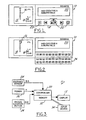
- a display control unit 10 of an intelligent vehicle highway navigation system 11 for motor vehicles that is low cost is contained in a housing 12 which is capable of being located in view of the driver but not in his driving sight distance.
- the display control unit 10 has a display 13 comprising first display or direction screen 14, shown on the left in the FIG., which displays an arrow or arrows 16 indicating the direction the vehicle is to take.
- the unit 10 may have an audio means to indicate to the driver that the vehicle should turn by means of sound device such as chimes or other similar device.
- a second or data screen 20 which is a display that has two lines of sixteen alphanumeric characters each although more or less characters maybe used.
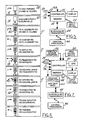
- the messages that are shown on the data screen 20 are routing segments 21 of the route and other alphanumeric information, some examples of which are illustrated in FIG. 4.
- FIG. 2 is the same unit as shown in FIG. 1 but is illustrated with the front cover flipped down displaying a modified alphanumeric keyboard 26 and other controls some of which are duplicates of those shown in FIG. 1.
- FIG. 3 illustrates in block diagrammatic form the basic system.
- the system comprises a wheel pulse generator 28 which functions as a distance or speed sensor; a housing as illustrated in FIGs 1 and 2 having a controller 30, a memory, a known-location button 24, the first 14 and second 20 display screens; an input or driver interface 34 and a source of power 36.
- the basic display unit 10 of FIG. 1 is a portable device which is releasably mounted in the vehicle and connected by means of a connector to receive the necessary inputs from the vehicle such as the wheel pulse input generator or distance sensor 28, power 36, and any other controls such as ignition on and also may include a connector means for addressing the memory for storing the several routes as will be hereinafter described.
- the controller 30 provides the operating system for the unit including operating the displays 13.
- the memory 32 is a non-volatile memory which may retain several different routes loaded therein for recall at any time. As will be shown, if the desired route is not stored in the memory, the vehicle operator pre-plans his route and loads the route, segment by segment 21, into the memory 32. As an example, in rental fleet applications, the fleet owner may install several routes to various known places from his rental location to such places as airports, hotels, train stations, public buildings, restaurants and other points of interest in the area as an aid to the rental driver who is not familiar with the area. As a part of each segment 21, the distance to be traveled along the segment, that is from the beginning to the end of the segment, is also loaded into the computer.
- a wheel speed sensor is found in most vehicles and senses the passage of a tooth wheel which is typically coupled to the drivetrain of the vehicle.
- the output signal of the sensor is supplied to a pulse forming circuit, wheel pulse input generator 28, which takes the output signal of the sensor and forms digital pulses, which are inputted to the controller 30. These pulses are used to measure the distance traveled.
- the known-location button 24 is typically activated when the vehicle has come to the end of a segment 21 and the display 14 indicates that there is still a distance to travel 18. The vehicle operator then will activate the known-location button 24 to cause the controller 30 to initialize the direction and data screens 14, 20 to the vehicle's present location and cause the next segment 21 of the route to be displayed on the data screen 20.
- the next segment has the location name of the present location and the location name of the next location where the vehicle will turn along with the distance to the turn which is shown on the distance screen 14.
- the input device 34 is some form of a keyboard device such as a keyboard, or a computer. If the input is a computer, the driver can enter his route at some other location than in the vehicle and when he/she gets into the vehicle, the computer can be connected to the memory 32 and the route downloaded into the memory.
- the computer may have some form of an routing and map data program that will allow the operator to develop his unique route.
- the routing segments 21 to transport a vehicle from a beginning location 38 to a destination location 40 there is illustrated the routing segments 21 to transport a vehicle from a beginning location 38 to a destination location 40.
- the first box shows the last message which was displayed, and in particular the message which was displayed when the ignition was turned off.
- the location is the place the vehicle is parked and is the beginning location 38.
- the vehicle operator then scrolls up the various routes which are located in the computer until the name of the desired destination location 40 is on the screen 20.
- the direction screen 14 shows the distance that the trip will cover.
- the next segment 21 is brought into view by depressing the known-location button 24.
- This segment 21 tells the vehicle operator to go from his parking place to the street a distance of 0.02 mi and when he arrives at the street, he must make a right turn.
- the bar graph 42 located above the distance measurement is a visual signal showing the distance counted down to the turn. Just prior to the distance traveled being counted down to zero indicating a turn, an audible means such as a chime or buzzer sounds telling the driver that he/she is approaching an intersection and there is a turn needed in the direction indicated.
- the first screen 14 also gives a visual indication of the direction the vehicle is to turn.
- the data screen 20 scrolls to the next segment 21 which shows the present location on the second line and on which street the route is going to take on the first line. Again on the direction or first screen 14, the distance is indicated and the direction arrows tell the vehicle operator to turn left onto Inkster Road which is the name on the first line of the segment of the data display 20.
- the route continues and the displays change each time the distance counts down to zero.
- the vehicle operator can depress the know-location button 24 which resets the distance to zero and causes the screens 13 to scroll to the next segment and, under proper control, updates the distance of the segment 21.
- the strength of the system is that the distance sensor 28 as is found in most vehicles is extremely accurate, far more than most other routing inputs and sensors, so that the distance to be traveled can be relied upon. It is found that the distance sensor 28 has an error of 0.2% to 0.3%.
- the system also includes an in-vehicle radio or RF transceiver 44. This allows communication to and from a central processor 46 for assistance in route planning.
- the central processor 46 provides routing segment 21 to take and may take into account any known route changes required by detours, accidents, etc.
- the route is transmitted from the central processor 46 and is stored in the memory/controller 30/32 of the system.
- the controller 30 receives the distance sensor 28 signals and power 36 from the vehicle to operate the system.
- the RF transceiver 44 communicates on cellular systems, spread spectrum telecommunications systems or any similar systems.
- an in-vehicle routing computer 48 and map data base 50 is added to the memory/controller 30/32.
- the operator provides the map data base 50 which may be in the form of a compact disc or other means and which is interrogated by the routing computer 48 to generate the route.
- the vehicle operator enters the initial location and the destination location.
- the vehicle operator may have to enter both the initial location and the destination in geodetic coordinates or maybe by common names such as City Airport or Joe Muer's Restaurant.
- the routing computer 48 and the map data base 50 compute the route to be taken and load the route into the memory 32 and the controller 30 ultimately displays the routing segments 21 as indicted above.
- the vehicle operator has communication time fees and central processor fees. In return he is able to get the latest and most up to date routing information. This of course depends upon the different inputs to the central processor 46 such as road maintenance information, detours, accident information, traffic density to name but a few inputs. In high traffic density areas, the communication time between the vehicle and the central processor 46 can become significant.
- the route is transmitted from the central processor 46 and is stored in the memory/controller 30/32 of the system.
- the controller 30 receives the distance sensor signals 28 and power 36 from the vehicle to operate the system.
- the RF transceiver 44 communicates on cellular systems, spread spectrum telecommunications systems or any similar systems.
- the vehicle operator has to maintain one or more map data bases 50 which cover a certain geographic area. If the vehicle goes beyond the limits of the map data base 50, then the vehicle operator must, through the input device 34 add the necessary segments 21 to complete his route. In short, the selection of either system is a matter of cost and availability.
- GPS device 52 is provided to make this a GPS based system.
- a routing computer 48 and map data base 50 are also provided. If the GPS device 52 is activated, the GPS is used to provide the initial location and may also indicate to the controller 30 when the vehicle has strayed from its route. In that situation, the controller 30 can be programmed to inform the vehicle operator and so that he may get back on course.
- the map data base 50 is used to generate the several segments 21 of the route as explained with FIG. 6 and cause the segments to be displayed on the display 13.
- the RF transceiver 44 when activated, can provide route updates which are beyond the capability of the map data base 50 stored in the vehicle unit.
- the use of the RF transceiver 44 may be under the control of the vehicle operator so that he has control of the payment of communication fees.
- the routing computer 48 can be programmed to indicate when the attached map data base 50 does not have the sufficient scope to complete the routing and that it is necessary to communicate with the central processor 46 for additional routing.
- the design of the system may also be such that the vehicle operator is not aware when the capacity of the map data base 50 is exceeded and the routing computer 48 "calls up" the central processor 46.
- the vehicle operator can program the routing computer 48 to make sure that he is directed by the best route.
- miscellaneous on-off inputs 54 are provided which may be to change the back lighting of the unit 10 when the head lights are on or if a direction sensor or compass device 56 is added and when the rear window defroster is activated causing an additional electromagnet field to be generated which interferes with the operation of the compass 56, the compass output is corrected.
- the system includes Ali-ScoutTM control by the IR transceiver 58.
- This part of the system provides communication to roadside beacons 60 and beacon controllers 62 which provide information to the vehicle about the routing by the next segment 21 links of the vehicle route.
- An important part of the IR roadside beacons 60 is that all vehicles passing a roadside beacon receive routes at the same time. Thus the IR communication link can not be saturated as can RF links which communicate to each individual vehicle.
- the overall Ali-ScoutTM system will not be saturated because of the increasing number of vehicles which can happen with the addition of only the in-vehicle radio or RF transceiver 44.
- the system now has the capability of using its own “canned” routes as described in FIGs. 3 and 4; modifying them with GPS information as to latitude and longitude coordinates of the present location as described in FIG. 7, generating mapping information as described in FIG. 6.
- the various segments of the route can be modified in real-time to provide the "best" route that is known.
- the central processor 46 can receive updates as to road conditions and provide further modifications to the selected route segments.
- the controller 30 will receive as its first or priority route information, the information received from the beacons 60 and when it determines that the beacon information is through because the vehicle has gone beyond the beacon network, it will then address the routing computer 48 in a manner similar as explained for FIG 7.
- one method of loading selected routes into the memory 32 is by means of the keyboard illustrated in FIG. 2.
- Other methods of loading selected routes in the display control unit 10 are by means of a map data base and routing algorithm running on a personal computer.
- the routing algorithm automatically generates routes and stores them into the computer until they are downloaded to the display control unit 10. Downloading can be done in or out of the vehicle via a hardwired serial link through the connector or other means
- the vehicle operator loads into the memory 32 of the display control unit 10, the segments 21 of several known routes which he typically takes and means are provided for selection of a desired route.
- a desired route is good for rental cars and used by the travelers to go from the airport or similar location to various hotels, restaurants, major landmarks, etc.
- both visual means such as by a display screens 13 and audio means such as by voice commands emanating from the display control unit 10 assure the vehicle operator that he is "on course".
- tolls can be collected and billed to a central billing by the transmission of a vehicle identification, messages may be stored in the central processor 46 and when a vehicle addresses the central processor 46, such messages may be transmitted to the vehicle operator.
Landscapes
- Engineering & Computer Science (AREA)
- Radar, Positioning & Navigation (AREA)
- Remote Sensing (AREA)
- Physics & Mathematics (AREA)
- General Physics & Mathematics (AREA)
- Mathematical Physics (AREA)
- Automation & Control Theory (AREA)
- Navigation (AREA)
- Traffic Control Systems (AREA)
- Refuge Islands, Traffic Blockers, Or Guard Fence (AREA)
- Instructional Devices (AREA)
Description
Claims (2)
- An intelligent highway vehicle navigation system for a vehicle having an in-vehicle unit and an out-of-vehicle processing means which in-vehicle unit including:a wheel pulse input signal generator (28);a power supply (36);global positioning means (52) for determining the initial and present position of the vehicle;a memory unit (32) adapted to contain a plurality of routes and segments thereof;an input device (34) for inputting into the memory unit (32) the destination location of the route;a display means (13) for displaying graphic symbols indicating the direction of travel of the vehicle for each route segment (21), and having a data display unit (2) for displaying alphanumerical symbols describing several segments (21) of the route, anda controller adapted to receive the signals generated by the wheel pulse input signal generator (28) and the global positioning means (52), the controller (30) being arranged to operate the display means (13) to present successive segments (21) of the route in response to the distance travelled as measured by the pulses from the wheel pulse input signal generator (28),radio-frequency means (44) for communication between the memory unit (32) and the out-of-vehicle processing means (46) for addressing the out-of-vehicle processing means (46) for the generation and transmission of route segments and travel information to the memory unit(32) of the on-vehicle unit wherein a routing computer (48) and an in-vehicle infrared transceiver means (58) are respectively coupled to the controller (30), the controller (30) being arranged to communicate with roadside infrared beacons (60) for receiving traffic routing information via the in-vehicle infrared transceiver means (58), and the controller (30) is arranged to address the routing computer (48) once the information has been received from the roadside beacons (60).
- A vehicle navigation system as claimed in Claim 1, wherein the memory unit (32) includes addresses, street names and points of interest.
Applications Claiming Priority (3)
| Application Number | Priority Date | Filing Date | Title |
|---|---|---|---|
| US307952 | 1994-09-16 | ||
| US08/307,952 US5565874A (en) | 1994-09-16 | 1994-09-16 | Expandable, multi-level intelligent vehicle highway system |
| PCT/US1995/010720 WO1996008692A1 (en) | 1994-09-16 | 1995-08-22 | Expandable, multi-level intelligent vehicle highway system |
Publications (2)
| Publication Number | Publication Date |
|---|---|
| EP0781397A1 EP0781397A1 (en) | 1997-07-02 |
| EP0781397B1 true EP0781397B1 (en) | 2003-07-09 |
Family
ID=23191879
Family Applications (1)
| Application Number | Title | Priority Date | Filing Date |
|---|---|---|---|
| EP95930925A Expired - Lifetime EP0781397B1 (en) | 1994-09-16 | 1995-08-22 | Intelligent vehicle highway system |
Country Status (8)
| Country | Link |
|---|---|
| US (1) | US5565874A (en) |
| EP (1) | EP0781397B1 (en) |
| JP (1) | JPH10505901A (en) |
| AU (1) | AU697131B2 (en) |
| BR (1) | BR9508954A (en) |
| DE (1) | DE69531248T2 (en) |
| MX (1) | MX9701980A (en) |
| WO (1) | WO1996008692A1 (en) |
Families Citing this family (65)
| Publication number | Priority date | Publication date | Assignee | Title |
|---|---|---|---|---|
| US8352400B2 (en) | 1991-12-23 | 2013-01-08 | Hoffberg Steven M | Adaptive pattern recognition based controller apparatus and method and human-factored interface therefore |
| US10361802B1 (en) | 1999-02-01 | 2019-07-23 | Blanding Hovenweep, Llc | Adaptive pattern recognition based control system and method |
| JP3552171B2 (en) * | 1994-06-21 | 2004-08-11 | 富士通株式会社 | Automatic charge settlement system and storage medium with wireless communication function for the system, frequency conversion device for the system, writing device for the system, settlement device for the system, payment device for the system, and inquiry device for the system |
| JPH0886662A (en) * | 1994-07-18 | 1996-04-02 | Sumitomo Electric Ind Ltd | In-vehicle traveling route display device, road information transmission device, route guidance system, and display method for navigation system |
| DE69521783T2 (en) * | 1994-08-08 | 2002-04-25 | Siemens Ag | NAVIGATION DEVICE FOR A LANDING VEHICLE WITH MEANS FOR GENERATING AN EARLY VOICE MESSAGE WITH MULTIPLE ELEMENTS, AND VEHICLE THEREFOR |
| DE19516476A1 (en) * | 1995-05-05 | 1996-11-07 | Bosch Gmbh Robert | Device for informing a driver |
| JPH08327380A (en) * | 1995-05-29 | 1996-12-13 | Sony Corp | Navigation device and display method |
| US5951620A (en) * | 1996-01-26 | 1999-09-14 | Navigation Technologies Corporation | System and method for distributing information for storage media |
| US5877704A (en) * | 1996-06-28 | 1999-03-02 | Denso Corporation | Parking-site reservation control system |
| US8526971B2 (en) | 1996-08-15 | 2013-09-03 | Snaptrack, Inc. | Method and apparatus for providing position-related information to mobile recipients |
| US6199045B1 (en) * | 1996-08-15 | 2001-03-06 | Spatial Adventures, Inc. | Method and apparatus for providing position-related information to mobile recipients |
| US6985742B1 (en) * | 1996-08-15 | 2006-01-10 | Spatial Adventures, Inc. | Method and apparatus for providing position-related information to mobile recipients |
| US5925090A (en) * | 1996-08-16 | 1999-07-20 | Alpine Electronics, Inc. | Sign text display method and apparatus for vehicle navigation system |
| JPH10132587A (en) * | 1996-10-31 | 1998-05-22 | Mitsumi Electric Co Ltd | Car navigation system with FM multiplex broadcast reception function |
| JPH1114391A (en) * | 1997-06-20 | 1999-01-22 | Yamaha Motor Co Ltd | Screen display method for navigation device |
| US6154703A (en) * | 1997-06-20 | 2000-11-28 | Yamaha Hatsudoki Kabushiki Kaisha | Control for vehicle navigational system |
| JPH1114390A (en) * | 1997-06-20 | 1999-01-22 | Yamaha Motor Co Ltd | Route guidance method by navigation device |
| US6157890A (en) * | 1997-06-20 | 2000-12-05 | Yamaha Hatsudoki Kabushiki Kaisha | Motorcycle navigation system |
| US5991690A (en) * | 1997-07-02 | 1999-11-23 | Trimble Navigation Limited | Navigation system incorporating simplified location display |
| US6707421B1 (en) * | 1997-08-19 | 2004-03-16 | Siemens Vdo Automotive Corporation | Driver information system |
| US6680694B1 (en) * | 1997-08-19 | 2004-01-20 | Siemens Vdo Automotive Corporation | Vehicle information system |
| US6801763B2 (en) | 1997-10-29 | 2004-10-05 | Metro One Telecommunications, Inc. | Technique for effectively communicating travel directions |
| US7268700B1 (en) | 1998-01-27 | 2007-09-11 | Hoffberg Steven M | Mobile communication device |
| US7266560B2 (en) * | 1998-01-30 | 2007-09-04 | Navteq North America, Llc | Parcelized geographic data medium with internal spatial indices and method and system for use and formation thereof |
| ATE288115T1 (en) * | 1998-05-22 | 2005-02-15 | Hans-Detlef Brust | DEVICE AND METHOD FOR FINDING A PARKED VEHICLE |
| US6078864A (en) * | 1998-07-17 | 2000-06-20 | Magellan Dis, Inc. | Navigation system with predetermined indication of next maneuver |
| US7277424B1 (en) * | 1998-07-21 | 2007-10-02 | Dowling Eric M | Method and apparatus for co-socket telephony |
| US6535743B1 (en) | 1998-07-29 | 2003-03-18 | Minorplanet Systems Usa, Inc. | System and method for providing directions using a communication network |
| US6405033B1 (en) | 1998-07-29 | 2002-06-11 | Track Communications, Inc. | System and method for routing a call using a communications network |
| US6522875B1 (en) | 1998-11-17 | 2003-02-18 | Eric Morgan Dowling | Geographical web browser, methods, apparatus and systems |
| US7966078B2 (en) | 1999-02-01 | 2011-06-21 | Steven Hoffberg | Network media appliance system and method |
| US6417782B1 (en) | 2000-06-22 | 2002-07-09 | Larry Dean Darnall | Driver's emergency alert system |
| DE10030805A1 (en) * | 2000-06-29 | 2002-01-10 | Nokia Mobile Phones Ltd | Method and mobile station for guidance |
| US7035932B1 (en) | 2000-10-27 | 2006-04-25 | Eric Morgan Dowling | Federated multiprotocol communication |
| US6901429B2 (en) | 2000-10-27 | 2005-05-31 | Eric Morgan Dowling | Negotiated wireless peripheral security systems |
| US6965914B2 (en) | 2000-10-27 | 2005-11-15 | Eric Morgan Dowling | Negotiated wireless peripheral systems |
| US6828924B2 (en) * | 2001-11-06 | 2004-12-07 | Volvo Trucks North America, Inc. | Integrated vehicle communications display |
| DE10162359B4 (en) * | 2001-12-18 | 2012-10-31 | Robert Bosch Gmbh | Method for providing route data for a navigation device |
| US6718906B2 (en) * | 2002-06-03 | 2004-04-13 | Volvo Trucks North America, Inc. | Dual scale vehicle gauge |
| US9733625B2 (en) | 2006-03-20 | 2017-08-15 | General Electric Company | Trip optimization system and method for a train |
| US10308265B2 (en) | 2006-03-20 | 2019-06-04 | Ge Global Sourcing Llc | Vehicle control system and method |
| US10569792B2 (en) | 2006-03-20 | 2020-02-25 | General Electric Company | Vehicle control system and method |
| US8102253B1 (en) | 2002-06-27 | 2012-01-24 | Earthcomber, Llc | System and method for notifying a user of people, places or things having attributes matching a user's stated preference |
| WO2004003705A2 (en) | 2002-06-27 | 2004-01-08 | Small World Productions, Inc. | System and method for locating and notifying a user of a person, place or thing having attributes matching the user's stated prefernces |
| US8427303B1 (en) | 2002-06-27 | 2013-04-23 | Geomass Limited Liability Company | System and method for providing media content having attributes matching a user's stated preference |
| US9950722B2 (en) | 2003-01-06 | 2018-04-24 | General Electric Company | System and method for vehicle control |
| US9818136B1 (en) | 2003-02-05 | 2017-11-14 | Steven M. Hoffberg | System and method for determining contingent relevance |
| US7076363B1 (en) * | 2003-07-17 | 2006-07-11 | America Online, Inc. | Using route narrative symbols |
| US7546207B2 (en) * | 2004-05-21 | 2009-06-09 | Gm Global Technology Operations, Inc. | Turn-by-turn navigation system with enhanced turn icon |
| US7522998B2 (en) * | 2004-11-05 | 2009-04-21 | Johnson Controls Technology Company | System and method for displaying vehicle location information |
| JP4581912B2 (en) * | 2005-08-24 | 2010-11-17 | 株式会社デンソー | Navigation device |
| US20080183490A1 (en) * | 2006-03-20 | 2008-07-31 | Martin William P | Method and computer software code for implementing a revised mission plan for a powered system |
| US9828010B2 (en) | 2006-03-20 | 2017-11-28 | General Electric Company | System, method and computer software code for determining a mission plan for a powered system using signal aspect information |
| JP2008009915A (en) * | 2006-06-30 | 2008-01-17 | Pioneer Electronic Corp | Road sign determination apparatus, method and program |
| US8554475B2 (en) | 2007-10-01 | 2013-10-08 | Mitac International Corporation | Static and dynamic contours |
| EP2212648A1 (en) * | 2007-11-22 | 2010-08-04 | Nokia Corporation | Apparatus and computer program for providing navigational information to a secondary visual user interface of a portable electronic device and method of assembling this device |
| US8140263B2 (en) * | 2008-01-31 | 2012-03-20 | Victor Company Of Japan, Limited | Method for deriving conversion coefficient used for specifying position from value detected by various sensors, and navigation apparatus |
| US9834237B2 (en) | 2012-11-21 | 2017-12-05 | General Electric Company | Route examining system and method |
| TWI402483B (en) * | 2009-10-30 | 2013-07-21 | Univ Nat Taiwan | Navigation method and human interface apparatus thereof |
| US9254781B2 (en) * | 2010-02-02 | 2016-02-09 | Craig David Applebaum | Emergency vehicle warning device and system |
| US20120143410A1 (en) * | 2010-12-01 | 2012-06-07 | Aptera Motors, Inc. | Interactive driver system for an electric vehicle |
| US9702715B2 (en) | 2012-10-17 | 2017-07-11 | General Electric Company | Distributed energy management system and method for a vehicle system |
| US9682716B2 (en) | 2012-11-21 | 2017-06-20 | General Electric Company | Route examining system and method |
| US9669851B2 (en) | 2012-11-21 | 2017-06-06 | General Electric Company | Route examination system and method |
| CN104061938B (en) * | 2013-03-21 | 2017-11-10 | 高德信息技术有限公司 | A kind of air navigation aid, apparatus and system |
Family Cites Families (12)
| Publication number | Priority date | Publication date | Assignee | Title |
|---|---|---|---|---|
| JPS5633758B2 (en) * | 1973-05-08 | 1981-08-05 | ||
| US5422812A (en) * | 1985-05-30 | 1995-06-06 | Robert Bosch Gmbh | Enroute vehicle guidance system with heads up display |
| GB8726312D0 (en) * | 1987-11-10 | 1987-12-16 | Plessey Co Plc | Road vehicle route selection & guidance |
| US5206811A (en) * | 1989-11-10 | 1993-04-27 | Nissan Motor Company, Limited | Navigation system for automotive vehicle |
| US5323321A (en) * | 1990-06-25 | 1994-06-21 | Motorola, Inc. | Land vehicle navigation apparatus |
| JP2955073B2 (en) * | 1991-08-05 | 1999-10-04 | ビステオン・テクノロジーズ,エル・エル・シー | Vehicle navigation system |
| US5353034A (en) * | 1991-11-08 | 1994-10-04 | Sanden Corporation | Position information inputting apparatus for a vehicle travel guide system |
| DE4139581C2 (en) * | 1991-11-30 | 1999-01-07 | Bayerische Motoren Werke Ag | Navigation procedures for motor vehicles |
| US5291414A (en) * | 1992-04-14 | 1994-03-01 | Zexel Corporation Diahatsu-Nissan Ikebukuro | Navigation system for guiding a vehicle along a precomputed optimal route |
| EP0580166B1 (en) * | 1992-07-23 | 1999-06-16 | Aisin Aw Co., Ltd. | Vehicle navigation system |
| US5452212A (en) * | 1992-08-19 | 1995-09-19 | Aisin Aw Co., Ltd. | Navigation system for vehicle |
| JPH06137882A (en) * | 1992-10-28 | 1994-05-20 | Toyota Motor Corp | Vehicle route guidance device |
-
1994
- 1994-09-16 US US08/307,952 patent/US5565874A/en not_active Expired - Lifetime
-
1995
- 1995-08-22 JP JP8510199A patent/JPH10505901A/en active Pending
- 1995-08-22 WO PCT/US1995/010720 patent/WO1996008692A1/en not_active Ceased
- 1995-08-22 MX MX9701980A patent/MX9701980A/en not_active IP Right Cessation
- 1995-08-22 BR BR9508954A patent/BR9508954A/en not_active Application Discontinuation
- 1995-08-22 DE DE69531248T patent/DE69531248T2/en not_active Expired - Lifetime
- 1995-08-22 EP EP95930925A patent/EP0781397B1/en not_active Expired - Lifetime
- 1995-08-22 AU AU34133/95A patent/AU697131B2/en not_active Ceased
Also Published As
| Publication number | Publication date |
|---|---|
| JPH10505901A (en) | 1998-06-09 |
| DE69531248T2 (en) | 2004-04-15 |
| WO1996008692A1 (en) | 1996-03-21 |
| AU697131B2 (en) | 1998-09-24 |
| EP0781397A1 (en) | 1997-07-02 |
| US5565874A (en) | 1996-10-15 |
| MX9701980A (en) | 1998-02-28 |
| AU3413395A (en) | 1996-03-29 |
| BR9508954A (en) | 1997-11-25 |
| DE69531248D1 (en) | 2003-08-14 |
Similar Documents
| Publication | Publication Date | Title |
|---|---|---|
| US5565874A (en) | Expandable, multi-level intelligent vehicle highway system | |
| MXPA97001980A (en) | Expandable, multi-level intelligent vehicle highway system | |
| US6101443A (en) | Route search and navigation apparatus and storage medium storing computer programs for navigation processing with travel difficulty by-pass | |
| US6064941A (en) | Vehicle navigation apparatus and storage medium | |
| US5648768A (en) | System and method for identifying, tabulating and presenting information of interest along a travel route | |
| US6992598B2 (en) | Apparatus and method for providing travel information | |
| US20070021909A1 (en) | Navigation system | |
| EP0588082A1 (en) | Navigation system for vehicle | |
| EP0489915A1 (en) | Navigation apparatus and method | |
| US6253153B1 (en) | Vehicle navigation system and method | |
| US6240363B1 (en) | Navigation method, in particular for vehicles | |
| US20060111838A1 (en) | System and method for displaying vehicle location information | |
| JP3769817B2 (en) | Route search display device | |
| JP3389693B2 (en) | Route guidance device for vehicles | |
| JP2004140526A (en) | Onboard apparatus | |
| French | The evolving roles of vehicular navigation | |
| JP2003042787A (en) | Navigation system and navigation program | |
| WO1996004526A2 (en) | Vehicle navigation and route guidance system | |
| EP1302748B1 (en) | Method for displaying guide for vehicle-mounted navigator | |
| JP2002162242A (en) | Taxi information display device | |
| JPH08178678A (en) | Traffic information display device | |
| JPS6391512A (en) | Vehicle-borne position measuring and display apparatus | |
| JPH08293093A (en) | Information storage type vehicle guidance system | |
| KR100557802B1 (en) | A navigational system | |
| JP3480171B2 (en) | Vehicle location name display device |
Legal Events
| Date | Code | Title | Description |
|---|---|---|---|
| PUAI | Public reference made under article 153(3) epc to a published international application that has entered the european phase |
Free format text: ORIGINAL CODE: 0009012 |
|
| 17P | Request for examination filed |
Effective date: 19970226 |
|
| AK | Designated contracting states |
Kind code of ref document: A1 Designated state(s): DE FR GB IT |
|
| 17Q | First examination report despatched |
Effective date: 19981230 |
|
| RTI1 | Title (correction) |
Free format text: INTELLIGENT VEHICLE HIGHWAY SYSTEM |
|
| RTI1 | Title (correction) |
Free format text: INTELLIGENT VEHICLE HIGHWAY SYSTEM |
|
| GRAH | Despatch of communication of intention to grant a patent |
Free format text: ORIGINAL CODE: EPIDOS IGRA |
|
| RTI1 | Title (correction) |
Free format text: INTELLIGENT VEHICLE HIGHWAY SYSTEM |
|
| RAP1 | Party data changed (applicant data changed or rights of an application transferred) |
Owner name: SIEMENS VDO AUTOMOTIVE CORPORATION |
|
| GRAH | Despatch of communication of intention to grant a patent |
Free format text: ORIGINAL CODE: EPIDOS IGRA |
|
| GRAA | (expected) grant |
Free format text: ORIGINAL CODE: 0009210 |
|
| AK | Designated contracting states |
Designated state(s): DE FR GB IT |
|
| REG | Reference to a national code |
Ref country code: GB Ref legal event code: FG4D |
|
| REF | Corresponds to: |
Ref document number: 69531248 Country of ref document: DE Date of ref document: 20030814 Kind code of ref document: P |
|
| ET | Fr: translation filed | ||
| PLBE | No opposition filed within time limit |
Free format text: ORIGINAL CODE: 0009261 |
|
| STAA | Information on the status of an ep patent application or granted ep patent |
Free format text: STATUS: NO OPPOSITION FILED WITHIN TIME LIMIT |
|
| 26N | No opposition filed |
Effective date: 20040414 |
|
| PGFP | Annual fee paid to national office [announced via postgrant information from national office to epo] |
Ref country code: IT Payment date: 20060831 Year of fee payment: 12 |
|
| PG25 | Lapsed in a contracting state [announced via postgrant information from national office to epo] |
Ref country code: IT Free format text: LAPSE BECAUSE OF NON-PAYMENT OF DUE FEES Effective date: 20070822 |
|
| PGFP | Annual fee paid to national office [announced via postgrant information from national office to epo] |
Ref country code: FR Payment date: 20100901 Year of fee payment: 16 |
|
| PGFP | Annual fee paid to national office [announced via postgrant information from national office to epo] |
Ref country code: GB Payment date: 20100819 Year of fee payment: 16 |
|
| GBPC | Gb: european patent ceased through non-payment of renewal fee |
Effective date: 20110822 |
|
| REG | Reference to a national code |
Ref country code: FR Ref legal event code: ST Effective date: 20120430 |
|
| PG25 | Lapsed in a contracting state [announced via postgrant information from national office to epo] |
Ref country code: GB Free format text: LAPSE BECAUSE OF NON-PAYMENT OF DUE FEES Effective date: 20110822 Ref country code: FR Free format text: LAPSE BECAUSE OF NON-PAYMENT OF DUE FEES Effective date: 20110831 |
|
| PGFP | Annual fee paid to national office [announced via postgrant information from national office to epo] |
Ref country code: DE Payment date: 20120831 Year of fee payment: 18 |
|
| PG25 | Lapsed in a contracting state [announced via postgrant information from national office to epo] |
Ref country code: DE Free format text: LAPSE BECAUSE OF NON-PAYMENT OF DUE FEES Effective date: 20140301 |
|
| REG | Reference to a national code |
Ref country code: DE Ref legal event code: R119 Ref document number: 69531248 Country of ref document: DE Effective date: 20140301 |