EP0781007B1 - Method for creating routing information in an ATM communications network - Google Patents
Method for creating routing information in an ATM communications network Download PDFInfo
- Publication number
- EP0781007B1 EP0781007B1 EP95120259A EP95120259A EP0781007B1 EP 0781007 B1 EP0781007 B1 EP 0781007B1 EP 95120259 A EP95120259 A EP 95120259A EP 95120259 A EP95120259 A EP 95120259A EP 0781007 B1 EP0781007 B1 EP 0781007B1
- Authority
- EP
- European Patent Office
- Prior art keywords
- node
- nodes
- information
- routing information
- dtl
- Prior art date
- Legal status (The legal status is an assumption and is not a legal conclusion. Google has not performed a legal analysis and makes no representation as to the accuracy of the status listed.)
- Expired - Lifetime
Links
Images


Classifications
-
- H—ELECTRICITY
- H04—ELECTRIC COMMUNICATION TECHNIQUE
- H04L—TRANSMISSION OF DIGITAL INFORMATION, e.g. TELEGRAPHIC COMMUNICATION
- H04L45/00—Routing or path finding of packets in data switching networks
- H04L45/02—Topology update or discovery
- H04L45/04—Interdomain routing, e.g. hierarchical routing
-
- H—ELECTRICITY
- H04—ELECTRIC COMMUNICATION TECHNIQUE
- H04L—TRANSMISSION OF DIGITAL INFORMATION, e.g. TELEGRAPHIC COMMUNICATION
- H04L45/00—Routing or path finding of packets in data switching networks
- H04L45/34—Source routing
Definitions
- an output switching node S (S as "source node") a connection establishment message from a terminal connected to it, so in this for the entire route through the network to Destination switching node D (D as "destination node”), at which the desired target connection terminal is connected or at which a connection transition to another Network to be made, route information is determined and this in the PNNI protocol according to the form of the connection setup message before forwarding to the next one Mediation nodes are added.
- Said ATM communication networks can be in numerous subnetworks ("Peer Groups”), consisting of physical switching nodes (“nodes”) and physical connection lines ("physical links”) structured.
- PNNI protocol according to determine the nodes of a (hierarchically lowest) peer Group from their midst a so-called representative node (“Peer Group Leader"), which the entire peer group in shape of a single, logical, model node (“logical group node “or also called” parent node ”) in a hierarchical higher peer group.
- the hierarchy can be recursive in other hierarchy levels continue: Even in the hierarchically higher peer Group, a peer group leader election can take place again.
- the selected peer group leader again represents the entire hierarchy area built under him in one hierarchically next higher peer group than this would be Hierarchy area a single node.
- this peer group there are again logical, model connection lines between two neighboring nodes, with such a connecting line again a logically formed subset of all represents those physical connecting lines, which each from a physical switching node in the neighboring hierarchy areas.
- the hierarchical PNNI protocol is completed model network (for viewing: 3-dimensional grid) by adding further, purely logical connecting lines, the so-called "uplinks", which are in accordance with the PNNI protocol two nodes each (physically - if the node on lower end of the uplink is a physical node - or logically) from hierarchically different peer groups connect with each other.
- a hierarchically lowest peer leads from the border node Group, which is connected via a physical connection line a border node in a neighboring peer group is an uplink (also called “initial uplink") to a representative node, the so-called “upnode”, i.e. to the representative node “ancestor node” (i.e. parent node, or “grandparent node”, or grand ... grandparent node) of the neighboring border node, which corresponds to exactly one ancestor node of this side border node immediate neighboring nodes in a common hierarchical higher peer group.
- uplink also called "initial uplink”
- Such an (initial) uplink has with the result that all ancestor nodes (of this side Border node), which however is hierarchical belong to lower peer groups than said common hierarchically higher peer group, one uplink each (further also called “induced uplink”) to said upnode Contribute hierarchy picture.
- the hierarchical structure which ultimately corresponds to Configuration data of the individual nodes, can be handled very flexibly.
- the individual nodes of a grand ... grandparent peer Group different number of sub-hierarchy levels including related Have peer groups.
- the PNNI protocol-compliant exchange of data packets, "Hello Packets” and PNNI topology status data packets ("topology state packets” - PTSPs) via so-called route control channels ("Routing Control Channels") ensures that every physical Switching node of a hierarchically lowest peer Group have the same knowledge regarding the topology of this and all hierarchical ones above it in the hierarchy higher peer groups including all uplinks, also the same Knowledge of the occupancy of all included Nodes and connecting lines as well as the same knowledge regarding their properties (accessibility, skills, Characteristics, costs).
- the acquired topology knowledge can be shown in the form of a graph Store G1 in a node. He was in each of them current switching node (the one that uses this graph G1 for has created itself) as the starting node S.
- the object of the method according to the invention now exists in it, taking into account the existing occupancy information regarding all nodes and connecting lines this graph G1 and taking into account their properties, as well as the expressed claims of the present connection request to determine the best possible connection path and the determined information into a route information in such a way to implement that this complies with the PNNI protocol regulations, and therefore the connection establishment message on the way to next connection node can be given.
- the task is based on the procedure of the "Topology Aggregation for Hierarchical Routing in ATM Networks "by Whay C. Lee XP570739 Generic term of Claim 1 solved by its characterizing features.
- a graph G2 is determined, which emerges from graph G1, by putting all those nodes and connecting lines out of the Graphs G1 are removed which meet the conditions mentioned do not withstand.
- an optimal connection path is determined in such a way that detours via hierarchically higher peer groups with then returning hierarchically to what has already happened lower peer groups are taken into account. Are the exit and re-entry nodes at one and same peer group different, otherwise such Detour a superfluous loop and not an optimal one Show connection path.
- the connection setup message is the Route information as a result of information elements, so-called “Designated Transit List information elements (DTLs) "is given, with a preceding information element (Repeat indicator) Information element on the Cellar-like handling of these DTLs (push and Pop operations).
- DTLs Designated Transit List information elements
- Repeat indicator preceding information element
- Each information element contains DTL the description of exactly one route exactly one hierarchical peer group in the form of one or several node-link pair information as well as a pointer that points to one of these node-link pairs indicates.
- the one from the top Information element DTL of the basement store described The route starts with the exit node S and only contains Information regarding nodes and connecting lines in the hierarchically lowest peer group and ends if necessary with an uplink leading to an upnode at to whom the route continues, as it is in the next lower one basemented DTL is described.
- Each next-deeper DTL in the basement contains information for one Route through the hierarchically next higher peer group, whereby you by specifying the relevant ancestor node of the Start node, possibly followed by others Node and connection line information from the same peer Group and any uplink information as a conclusion.
- the deepest DTL contains information regarding a route through the hierarchically highest required peer group, starting with the Indication of the relevant ancestor node of the starting node and ending at a node, in the hierarchy area of which the destination node with the connected destination terminal is located.
- the PNNI protocol described design of the DTL basement storage At first it gives the impression of being able to Routes resulting from any sequence of hierarchical higher and hierarchically lower nodes do not exist be taken into account, and that it would be appropriate, the Algorithm for the search for an optimal connection path in such a way that routes with such consequences (pron with detours via hierarchically higher peer groups) from the start resign as it is in the specifications of the PNNI protocol, Version 1.0, Appendix H is the case.
- the method according to the invention solves the display problem such a detour route and forms also route information for them that complies with the PNNI protocol Regulations are sufficient.
- a graph G3 is derived from the above-mentioned graph G2, by removing all ancestor nodes of the output node S. all (horizontal) leading away from them Connection lines, which of these ancestor nodes to their neighboring nodes in the corresponding hierarchically higher ones would lead peer groups, as well as all of them ancestor nodes in the upward direction Uplinks.
- PNNI protocol e.g. using the Dijkstra routing algorithm a best route from the exit node S. to the target node D based on the graph G3 on known Determined way, with the uplinks remaining in graph G3 no different from all other (horizontal) connecting lines are to be treated.
- node-n D
- link-n-1 .., node-i + 1, link-i, .., link-1
- node-1 S
- node-1 ( S)
- link-1 .., link-i
- node-i + 1 .., link-n-1
- node-n ( D)
- a link link-i turns horizontal if node-i and node-i + 1 are assigned to the same hierarchy level, that is belong to the same hierarchical peer group.
- a link link-i turns out to be an uplink in the upward direction (or downward direction) if the hierarchy level of node node-i smaller (or larger) than the hierarchy level of nodes is node-i + 1.
- a sequence F3 is derived from the sequence F2, in which the nodes never descend in the given sequence with regard to their hierarchical level. Switching nodes and links from F2 may be replaced or deleted by others.
- a second Boolean auxiliary variable here called Below-HighestReachedLevel, which is initialized with FALSE.
- the associated horizontal is for a given uplink To determine the link in the hierarchically higher peer group:
- the graph G1 has m links (horizontal links and uplinks taken together).
- the number k from the set 1,2, ..., m represents a pointer to the interesting information regarding exactly one link (eg its identity information).
- the elements represent the assignment chain from the initial uplink to the possibly induced uplink, to the uplink which may be induced again, etc., to the horizontal link induced therefrom in a hierarchically higher peer group: which does ______________ mean:
- the table RelationTbl from RelationTbl [j q-1 ] is run through in order to get from one link to the next link and currentNodeLevel is always compared with the entries in LinkLevelTbl. Assuming that the value of CurrentNodeLevel is equal to the value of Link-LevelTbl [j r-1 ], j r-1 identifies the searched link, which should replace link-i.
- sequence F4 From sequence F3 you can create a sequence F4 as follows:
- a detour via or several peer groups returning to one that has already passed Peer group at a not yet re-entry node also when refilling the information elements the route information when the connection setup message arrives in a physical switching node to be passed (Transit node).
- the relevant stack-top DTL must be removed beforehand. If a certain hierarchy area is left, so must first have all those stack-top information elements DTL which route sections are removed by the respective Contain peer groups of the hierarchy area to be left. If, when forwarding a connection setup message, a hierarchically lowest peer group is re-entered, so new route sections have to be determined and new ones related to this DTLs are formed.
- the pointers in the individual DTLs must always be set or advanced so that the Receive a connection establishment message everyone's pointers received DTLs each point to a node-link pair, which either the receiving physical, hierarchically lowest Contains nodes or one of its ancestor nodes.
- the boundary node (S '), as an entry node in another Peer Group determines a new best route section up towards a destination node D '.
- the destination node D ' is the node-link pair to see which of the node-link pair in the stack-top of the received DTLs follows which the relevant pointer shows.
- the PNNI protocol stipulates that also the received link information, namely how to get to the node Knot D 'is coming, must be fully complied with.
- the hierarchy area represented by the destination node D ' is not entered at the designated border node, from where the continuation of the connection establishment in one Dead end could end. That it becomes in addition to D ' the horizontal link link-to-d 'still determines.
- the boundary node S ' which notes that it is for the present Connection establishment request is only a transit node and that received DTL cellar memory is incomplete, therefore forms starting from its own graph G1, a possibly reduced one Graph G1 'as follows:
- Graph G1 shows all nodes - including adjacent links - with a hierarchy level greater than or equal to the hierarchy level of the node D 'removed, but not D' itself and also not those uplinks for which D 'Upnode is and the link-to-D' assigned. That for all uplinks, which D 'as Upnode, do the following test:
- the graphs G2' and G3 ' are formed, quite analogous to the output node S the graphs G2 'and G3' has formed, and determined a DTL stack as described above where S 'is the function of S and D' is the function of D takes over (see description above).
- the method according to the invention can be in the output switching node be realized when the output switching node and the destination switching node belong to the same subnet and the route information with one or more Loops to further subnets are formed. It can through the exit switch for connection establishment for the first time the creation of routing information for a connection setup message (setup).
- the routing information in the Output switching nodes forming the sense of the method according to the invention itself is a transit communication system, so that the connection setup message (setup) is received and further processes the route information contained therein and for the following route to the destination switching node is trained.
- the output switching nodes belong to a first subnet and the destination switching node to another subnet, Identifiable bottlenecks can also be avoided by Loops should be included in the route.
- Procedures can include further Subnets are made in such a way that they leave a subnet several times is permitted or grinding is also permitted in other subnets without the connection being established would not be possible with the same conditions.
- the hierarchy of the ATM communication network shows an example three subnets TA, TB, TC.
- the first subnet includes TA the physical nodes A.1..6.
- Connection establishment is the node A.1 the output switching node and node A.6 the destination switching node.
- these starting and destination nodes must be different are not in the same peer group (subnet), too the use of detours can only be made through a transit node respectively.
- Another subnet TB includes Node B.1..5 and an additional further subnet TC Node C.1..4.
- the subnetworks TA, TB (peer groups of the lowest Hierarchy level) are at a higher hierarchy level to a network group TAB (peer group higher hierarchical level) are summarized and are each represented by a logical Node A, B represents.
- TAB peer group
- the nodes are interconnected by physical connection lines (physically left) connected.
- Left pb1,2,3 and pc1,2 between nodes of different subnets are additional Associated information.
- the nodes in which the route information according to FIGS. 1 to 3 is formed only see those with thick borders Peer Groups (the knowledge base stored in the respective node includes information about these peer groups). Instead of the physical connecting lines, which come from the hierarchical lowest peer group, they see the related uplinks. Only the respective border nodes even know about this assignment, share this knowledge but not the other nodes of the peer group.
- the graph G1 be stored in the form of a list of links including their delimiting nodes, ie G1 (A.1) - see FIG. 1: (pa2: A.2, A.1), (pa3: A.3, A.1), (pa4: A.4, A.5), (pa5: A.5, A.1), (pa6 : A.6, A.5), (ub1: A.2, B), (ub2: A.3, B), (ub3: A.4, B), (uc1: A.5, C), (uc2: A.6, C).
- the blocked lines are removed, namely (pa5: A.5, A.1), (pa6: A.6, A.5), and the graph G2 (A.1) is determined: (pa2: A.2, A.1), (pa3: A.3, A.1), (pa4: A.4, A.5), (ub1: A.2, B), (ub2: A .3, B), (ub3: A.4, B), (uc1: A.5, C), (uc2: A.6, C).
- All ancestor nodes including adjacent lines are removed, namely (hb1: B, A), (hb2: B, A), (hb3: B, A), (Uc1: A, C), (Uc2: A, C), (hc1: C, AB), (hc2: C, AB), and thus graph G3 (A.1) determines: (pa2: A.2, A.1), (pa3: A.3, A.1), (pa4: A.4, A.5), (ub1: A.2, B), (ub2: A .3, B), (ub3: A.4, B), (uc1: A.5, C), (uc2: A.6, C).
- Sequence F3 is determined: A.1, pa2, A.2, ub1, B, hb3, A, Uc1, C, hc2, AB.
- Sequence F4 is determined: A.1, pa2, A.2, ub1, A, hb1, B, hb3, A, Uc1, AB, hc1, C, hc2, AB.
- Node B.2 has saved the network it sees as graph G1 (B.2) - see Figure 2 with a thick frame: (pb4: B.1, B.2), (pb5: B.1, B.5), (pb6: B.4, B.5), (pb7: B.3, B.4), (pb8: B.2, B.3), (ua1: B.2, A), (ua2: B.3, A), (ua3: B.4, A), (hb1: B, A), (hb2: B, A), (hb3: B, A), (Uc1: A, C), (Uc2: A, C), (hc1: C, AB), (hc2: C, AB).
- the graph G1 '(B.2) is created: (pb4: B.1, B.2), (pb5: B.1, B.5), (pb6: B.4, B.5), (pb7: B.3, B.4), (pb8: B.2, B.3), (ua3: B.4, A)
- Node A.4 has the network it sees as graph G1 (A.4) stored, which with the stored from the output node A.1 Graph G1 (A.1) matches, see above and see Figure 1 (thick border).
- the node C.1 has saved the network it sees as a graph G1 (C.1), see FIG. 3: (pc3: C.1, C.2), (pc4: C.2, C.3), (pc5: C.3, C.4), (pc6: C.1, C.4), (uab1: C.1, AB), (uab2: C.4, AB) (hc1: C, AB), (Hc2: C, AB)
- the graph G1 '(C.1) results: (pc3: C.1, C.2), (pc4: C.2, C.3), (pc5: C.3, C.4), (pc6: C.1, C.4), (uab2: C.4, AB)
- node A.6 recognizes that the target terminal is directly connected to it is connected, it sends the connection setup message (setup) along the relevant UNI interface (no longer PNNI interface) to this, whereby, according to UNI protocol, no information elements DTLs are given. The route is complete.
Abstract
Description
Erhält in einem ATM-Kommunikationsnetz, welches nach den Prinzipien des PNNI-Protokolls des ATM Forums (ATM Forum Technical Committee Private Network-Node-Interface (PNNI) Specification, Version 1.0)operiert, ein Ausgangsvermittlungsknoten S (S wie "source node") eine Verbindungsaufbaumeldung von einem an ihm angeschlossenen Endgerät, so muß in diesem für den gesamten Leitweg durch das Netz bis hin zum Zielvermittlungsknoten D (D wie "destination node"), an welchem das gewünschte Zielverbindungs-Endgerät angeschlossen ist oder an welchem ein Verbindungsübergang in ein anderes Netz vorgenommen werden soll, eine Leitweginformation ermittelt und diese in PNNI-Protokoll gemäßer Form der Verbindungsaufbaumeldung vor dem Weiterleiten zum nachfolgenden Vermittlungsknoten beigefügt werden.Received in an ATM communication network, which according to the Principles of the ATM Forum's PNNI protocol Technical Committee Private Network Node Interface (PNNI) Specification, Version 1.0) operates, an output switching node S (S as "source node") a connection establishment message from a terminal connected to it, so in this for the entire route through the network to Destination switching node D (D as "destination node"), at which the desired target connection terminal is connected or at which a connection transition to another Network to be made, route information is determined and this in the PNNI protocol according to the form of the connection setup message before forwarding to the next one Mediation nodes are added.
Besagte ATM-Kommunikationsnetze können in zahlreiche Teilnetze ("Peer Groups"), bestehend aus physikalischen Vermittlungsknoten ("nodes") und physikalischen Verbindungsleitungen ("physical links") strukturiert sein. PNNI-Protokoll-gemäß bestimmen die Knoten einer (hierarchisch niedrigsten) Peer Group aus ihrer Mitte einen sogenannten Vertreterknoten ("Peer Group Leader"), der die gesamte Peer Group in Form eines einzigen, logischen, modellhaften Knotens ("logical group node" oder auch "parent node" genannt) in einer hierarchisch höheren Peer Group repräsentiert. Es bildet sich eine hierarchisch höhere Peer Group aus mehreren derartigen parent nodes, sowie den diese vernetzenden Verbindungsleitungen, wobei so eine Verbindungsleitung ("logical link") eine logisch gebildete Teilmenge all jener physikalischen Verbindungsleitungen repräsentiert, welche je zwei Grenzknoten der beiden benachbarten (hierarchisch niederen - "child" -) Peer Groups miteinander verbinden und per Administration mit einer identischen Kennzeichnung ("Aggregation Token" genannt) versehen wurden.Said ATM communication networks can be in numerous subnetworks ("Peer Groups"), consisting of physical switching nodes ("nodes") and physical connection lines ("physical links") structured. PNNI protocol according to determine the nodes of a (hierarchically lowest) peer Group from their midst a so-called representative node ("Peer Group Leader"), which the entire peer group in shape of a single, logical, model node ("logical group node "or also called" parent node ") in a hierarchical higher peer group. One forms hierarchically higher peer group from several such parents nodes, as well as the connecting lines connecting them, whereby such a logical link is a logical formed subset of all those physical connection lines represents which two border nodes each two neighboring (hierarchically lower - "child" -) peer Connect groups with each other and via administration with one identical identification (called "aggregation token") were provided.
Rekursiv kann sich die Hierarchie in weiteren Hierarchieebenen fortsetzen: Auch in der hierarchisch höheren Peer Group kann abermals eine Peer Group Leader Wahl stattfinden. Der dabei gewählte Peer Group Leader repräsentiert erneut den gesamten unter ihm aufgebauten Hierarchiebereich in einer hierarchisch nächst höheren Peer Group als wäre dieser Hierarchiebereich ein einziger Knoten. In dieser Peer Group gibt es erneut logische, modellhafte Verbindungsleitungen zwischen je zwei Nachbarknoten, wobei eine solche Verbindungsleitung wiederum eine logisch gebildete Teilmenge all jener physikalischen Verbindungsleitungen repräsentiert, welche von je einem physikalischen Vermittlungsknoten in den benachbarten Hierarchiebereichen begrenzt werden.The hierarchy can be recursive in other hierarchy levels continue: Even in the hierarchically higher peer Group, a peer group leader election can take place again. The selected peer group leader again represents the entire hierarchy area built under him in one hierarchically next higher peer group than this would be Hierarchy area a single node. In this peer group there are again logical, model connection lines between two neighboring nodes, with such a connecting line again a logically formed subset of all represents those physical connecting lines, which each from a physical switching node in the neighboring hierarchy areas.
Vervollständigt wird das PNNI-Protokoll-gemäße hierarchische modellhafte Netz (für die Anschauung: 3-dimensionales Gitter) durch die Hinzunahme von weiteren, rein logischen Verbindungsleitungen, den sogenannten "Uplinks", welche PNNI-Protokoll-gemäß je zwei Knoten (physikalisch - falls der Knoten am unteren Ende des Uplinks ein physikalischer Knoten ist - oder logisch) aus hierarchisch unterschiedlich hohen Peer Groups miteinander verbinden.The hierarchical PNNI protocol is completed model network (for viewing: 3-dimensional grid) by adding further, purely logical connecting lines, the so-called "uplinks", which are in accordance with the PNNI protocol two nodes each (physically - if the node on lower end of the uplink is a physical node - or logically) from hierarchically different peer groups connect with each other.
So führt vom Grenzknoten einer hierarchisch niedrigsten Peer Group, welcher über eine physikalische Verbindungsleitung mit einem Grenzknoten in einer benachbarten Peer Group verbunden ist, ein Uplink (des weiteren auch "initialer Uplink" genannt) zu einem Vertreterknoten, dem sogenannten "upnode", d.h. zu jenem Vertreterknoten "ancestor node" (d.h. parent node, bzw. "grandparent node", bzw. grand...grandparent node) des benachbarten Grenzknotens, welcher zu genau einem bestimmten ancestor node des diesseitigen Grenzknotens ein unmittelbarer Nachbarknoten in einer gemeinsamen hierarchisch höheren Peer Group ist. Ein derartiger (initialer) Uplink hat zur Folge, daß auch alle ancestor nodes (des diesseitigen Grenzknotens), welche jedoch je einer hierarchisch niedrigeren Peer Group angehören als besagte gemeinsame hierarchisch höhere Peer Group, je einen Uplink (des weiteren auch "induzierter Uplink" genannt) zu besagtem upnode dem Hierarchiebild beisteuern.A hierarchically lowest peer leads from the border node Group, which is connected via a physical connection line a border node in a neighboring peer group is an uplink (also called "initial uplink") to a representative node, the so-called "upnode", i.e. to the representative node "ancestor node" (i.e. parent node, or "grandparent node", or grand ... grandparent node) of the neighboring border node, which corresponds to exactly one ancestor node of this side border node immediate neighboring nodes in a common hierarchical higher peer group. Such an (initial) uplink has with the result that all ancestor nodes (of this side Border node), which however is hierarchical belong to lower peer groups than said common hierarchically higher peer group, one uplink each (further also called "induced uplink") to said upnode Contribute hierarchy picture.
Die hierarchische Strukturierung, welche letztlich auf entsprechenden Konfigurierungsdaten der einzelnen Knoten beruht, kann dabei sehr flexibel gehandhabt werden. Insbesondere können die einzelnen Knoten einer grand...grandparent Peer Group unterschiedlich viele Subhierarchieebenen samt diesbezüglichen Peer Groups haben.The hierarchical structure, which ultimately corresponds to Configuration data of the individual nodes, can be handled very flexibly. In particular can the individual nodes of a grand ... grandparent peer Group different number of sub-hierarchy levels including related Have peer groups.
Der PNNI-Protokoll-gemäße Austausch von Datenpaketen, "Hello-Packets" sowie PNNI-Topologiestatus Datenpaketen ("Topology-State-Packets" - PTSPs) über sogenannte Leitwegkontrollkanäle ("Routing-Control-Channels") sorgt dafür, daß jeder physikalische Vermittlungsknoten einer hierarchisch niedrigsten Peer Group dasselbe Wissen bezüglich der Topologie dieser und aller in der Hierarchie darüber befindlichen hierarchisch höheren Peer Groups inklusive aller Uplinks, ferner dasselbe Wissen bezüglich der Belegungsauslastung aller darin enthaltenen Knoten und Verbindungsleitungen sowie dasselbe Wissen bezüglich deren Eigenschaften (Erreichbarkeit, Fähigkeiten, Merkmale, Kosten) erwirbt.The PNNI protocol-compliant exchange of data packets, "Hello Packets" and PNNI topology status data packets ("topology state packets" - PTSPs) via so-called route control channels ("Routing Control Channels") ensures that every physical Switching node of a hierarchically lowest peer Group have the same knowledge regarding the topology of this and all hierarchical ones above it in the hierarchy higher peer groups including all uplinks, also the same Knowledge of the occupancy of all included Nodes and connecting lines as well as the same knowledge regarding their properties (accessibility, skills, Characteristics, costs).
Das erworbene Topologiewissen läßt sich in Form eines Graphen G1 in einem Knoten abspeichern. In ihm sei der jeweils aktuelle Vermittlungsknoten (der, der diesen Graphen G1 für sich erstellt hat) als Ausgangsknoten S besonders markiert.The acquired topology knowledge can be shown in the form of a graph Store G1 in a node. He was in each of them current switching node (the one that uses this graph G1 for has created itself) as the starting node S.
Äußert nun ein am Ausgangsknoten angeschlossenes Endgerät den Wunsch, mit dem Endgerät einer gewissen Zieladresse verbunden zu werden, so gestatten die per PNNI-Routing-Protokoll ausgetauschten Daten im Graphen G1 jenen Zielknoten D zu bestimmen, welcher die Erreichbarkeit des Zielendgeräts proklamiert und dabei der hierarchisch niedrigst möglichen Peer Group angehört.Now expresses a terminal connected to the output node Desire to be connected to the terminal of a certain destination address to be exchanged via the PNNI routing protocol Data in graph G1 to determine that target node D which proclaims the accessibility of the target device and belongs to the lowest hierarchical peer group possible.
Das ATM Forum Technical Committee Private Network-Node-Interface (PNNI) in der Spezification, Version 1.0, Anhang H sieht dabei jedoch nicht die Möglichkeit vor, auch vorteilhafte Umwege über ein oder mehrere Peer Groups mit Rückkehr zur bereits passierten Peer Group in die Leitwegsuche einzubeziehen, dadurch ist es mitunter nicht möglich eine Vermittlungsanforderung entsprechend zu erfüllen.The ATM Forum Technical Committee Private Network Node Interface (PNNI) in the Specification, Version 1.0, Appendix H. however, not the possibility, also advantageous detours via one or more peer groups with return to the already passed peer group in the route search, as a result, it may not be possible to make an operator request to meet accordingly.
Die Aufgabe des erfindungsgemäßen Verfahrens besteht nun darin, unter Beachtung der vorhandenen Belegungsauslastungsinformation bezüglich aller Knoten und Verbindungsleitungen dieses Graphen G1 und unter Beachtung ihrer Eigenschaften, sowie der geäußerten Ansprüche des vorliegenden Verbindungswunsches einen bestmöglichen Verbindungsweg zu ermitteln und die ermittelte Information in eine Leitweginformation derart umzusetzen, daß diese den PNNI-Protokoll-Vorschriften genügt, und deshalb der Verbindungsaufbaumeldung auf dem Weg zum nächsten Verbindungsknoten mitgegeben werden kann. Die Aufgabe wird durch das Verfahen ausgehend von dem im Dokument "Topology Aggregation for Hierarchical Routing in ATM Networks" von Whay C. Lee XP570739 erläuterten Oberbegriff des Patentanspruchs 1 durch dessen kennzeichnende Merkmale gelöst.The object of the method according to the invention now exists in it, taking into account the existing occupancy information regarding all nodes and connecting lines this graph G1 and taking into account their properties, as well as the expressed claims of the present connection request to determine the best possible connection path and the determined information into a route information in such a way to implement that this complies with the PNNI protocol regulations, and therefore the connection establishment message on the way to next connection node can be given. The task is based on the procedure of the "Topology Aggregation for Hierarchical Routing in ATM Networks "by Whay C. Lee XP570739 Generic term of Claim 1 solved by its characterizing features.
Ein Graph G2 wird bestimmt, der aus dem Graphen G1 hervorgeht, indem all jene Knoten und Verbindungsleitungen aus dem Graphen G1 entfernt werden, welche den genannten Bedingungen nicht standhalten.A graph G2 is determined, which emerges from graph G1, by putting all those nodes and connecting lines out of the Graphs G1 are removed which meet the conditions mentioned do not withstand.
Anschließend wird ein optimaler Verbindungsweg derart bestimmt, daß Umwege über hierarchisch höhere Peer Groups mit anschließender Rückkehr zu bereits passierten hierarchisch niedrigeren Peer Groups mitberücksichtigt werden. Dabei sind die Austrittsknoten und Wiedereintrittsknoten bei ein und derselben Peer Group unterschiedlich, sonst würde solch ein Umweg ein höchst überflüssige Schleife und keinen optimalen Verbindungsweg darstellen.Then an optimal connection path is determined in such a way that detours via hierarchically higher peer groups with then returning hierarchically to what has already happened lower peer groups are taken into account. Are the exit and re-entry nodes at one and same peer group different, otherwise such Detour a superfluous loop and not an optimal one Show connection path.
Auch wenn sich alles Nachfolgende auf umwegartige Leitwege ("Routen") konzentriert, so darf nicht übersehen werden, daß das erfindungsgemäße Verfahren auch für den Normalfall, bei dem eine beste, umweglose Route zur Verfügung steht, diese auch findet und für sie ebenso korrekt die entsprechende Leitweginformation bildet.Even if everything following follows on detour-like routes ("Routes") concentrated, it must not be overlooked that the method according to the invention also for the normal case which has a best route without detour, this one also finds the right one for her Routing information forms.
Die sich ergebende optimale Route kann prinzipiell beliebig viele Übergänge von einer hierarchisch höheren zu einer hierarchisch niedrigeren Peer Group und umgekehrt von einer hierarchisch niedrigeren zu einer hierarchisch höheren Peer Group enthalten, wobei bei jedem einzelnen Übergang prinzipiell beliebig viele, d.h. null, eins, zwei,...oder n <=102 Hierarchieebenen übersprungen werden dürfen.In principle, the resulting optimal route can be arbitrary many transitions from a hierarchically higher to a hierarchical one lower peer group and vice versa from a hierarchical lower to a hierarchically higher peer group included, with every single transition in principle any number, i.e. zero, one, two, ... or n <= 102 hierarchy levels may be skipped.
PNNI-Protokoll-gemäß wird der Verbindungsaufbaumeldung die Leitweginformation als Folge von Informationselementen, sogenannten "Designated-Transit-List-Informationselementen (DTLs)" mitgegeben, wobei ein vorausgehendes Informationselement (Repeat-Indicator) Informationselement auf die Kellerspeicher-(stack)-artige Handhabung dieser DTLs (Pushund Pop-Operationen) hinweist. Dabei enthält jedes Informationselement DTL die Beschreibung von genau einer Route durch genau eine hierarchische Peer Group in Form von einem oder mehreren Knoten-Link-Paar Angaben sowie einem Zeiger, der auf eines dieser Knoten-Link-Paare deutet. Die vom obersten Informationselement DTL des Kellerspeichers beschriebene Route beginnt dabei mit dem Ausgangsknoten S und enthält nur Angaben bezüglich Knoten und Verbindungsleitungen in der hierarchisch niedrigsten Peer Group und endet gegebenenfalls mit der Angabe eines Uplinks, der zu einem upnode führt, bei dem die Route sich fortsetzt, und zwar so, wie sie im nächst-tiefer gekellerten DTL beschrieben ist. Jedes nächst-tiefer im Kellerspeicher befindliche DTL enthält Angaben für je eine Route durch die hierarchisch nächst-höhere Peer Group, wobei sie mit der Angabe des diesbezüglichen ancestor nodes des Ausgangsknotens beginnen, eventuell gefolgt von weiteren Knoten- und Verbindungsleitungsangaben aus selbiger Peer Group und eventueller Uplink-Angabe als Abschluß. Das stacktiefste DTL enthält Angaben bezüglich einer Route durch die hierarchisch höchste benötigte Peer Group, beginnend mit der Angabe des diesbezüglichen ancestor nodes des Ausgangsknotens und endend bei einem Knoten, in dessen Hierarchiebereich sich der Zielknoten mit dem angeschlossenen Zielendgerät befindet.According to the PNNI protocol, the connection setup message is the Route information as a result of information elements, so-called "Designated Transit List information elements (DTLs) "is given, with a preceding information element (Repeat indicator) Information element on the Cellar-like handling of these DTLs (push and Pop operations). Each information element contains DTL the description of exactly one route exactly one hierarchical peer group in the form of one or several node-link pair information as well as a pointer that points to one of these node-link pairs indicates. The one from the top Information element DTL of the basement store described The route starts with the exit node S and only contains Information regarding nodes and connecting lines in the hierarchically lowest peer group and ends if necessary with an uplink leading to an upnode at to whom the route continues, as it is in the next lower one basemented DTL is described. Each next-deeper DTL in the basement contains information for one Route through the hierarchically next higher peer group, whereby you by specifying the relevant ancestor node of the Start node, possibly followed by others Node and connection line information from the same peer Group and any uplink information as a conclusion. The deepest DTL contains information regarding a route through the hierarchically highest required peer group, starting with the Indication of the relevant ancestor node of the starting node and ending at a node, in the hierarchy area of which the destination node with the connected destination terminal is located.
Die beschriebene PNNI-Protokoll-gemäße Gestaltung des DTL-Kellerspeichers erweckt zunächst den Anschein, als könnten Leitwege, welche aus beliebigen Folgen von hierarchisch höheren und hierarchisch niedrigeren Knoten bestehen, nicht berücksichtigt werden, und daß es wohl angezeigt wäre, den Algorithmus für die Suche eines optimalen Verbindungsweges derart zu gestalten, daß Routen mit derartigen Folgen (sprich mit Umwegen über hierarchisch höhere Peer Groups) von vornherein ausscheiden, wie es in der Spezifikations des PNNI-Protokolls, Version 1.0, Anhang H der Fall ist.The PNNI protocol described design of the DTL basement storage At first it gives the impression of being able to Routes resulting from any sequence of hierarchical higher and hierarchically lower nodes do not exist be taken into account, and that it would be appropriate, the Algorithm for the search for an optimal connection path in such a way that routes with such consequences (pron with detours via hierarchically higher peer groups) from the start resign as it is in the specifications of the PNNI protocol, Version 1.0, Appendix H is the case.
Das erfindungsgemäße Verfahren löst jedoch das Darstellungsproblem einer derartigen umwegbehafteten Route und bildet auch für sie Leitweginformationen, die den PNNI-Protokollgemäßen Vorschriften genügen.However, the method according to the invention solves the display problem such a detour route and forms also route information for them that complies with the PNNI protocol Regulations are sufficient.
Charakteristisch an der erfindungsgemäßen Lösung ist es, daß aus einer vorgegebenen Folge von hierarchisch höheren und hierarchisch niedrigeren Knoten, in welcher Uplinks durchaus auch in Abwärtsrichtung zu passieren wären, eine äquivalente Folge von Knoten und Verbindungsleitungen abgeleitet wird, welche hinsichtlich der Hierachieebenen dieser Knoten niemals absteigend verläuft, bei der also Uplinks niemals in Abwärtsrichtung zu passieren sind. Als Tribut des dadurch Erreichten kann ein und derselbe hierarchisch höhere (logische) Knoten mehrfach in der Folge auftreten (Schleifen), jedoch wird aufgrund der angegebenen Verbindungsleitungen eindeutig dafür gesorgt, daß die Austritts- und Wiedereintrittsgrenzknoten in den diesbezüglichen Child Peer Groups stets verschieden sind, was letztlich bedeutet, daß ein und derselbe physikalische Knoten niemals öfter als einmal passiert wird.It is characteristic of the solution according to the invention that from a given sequence of hierarchically higher and hierarchically lower nodes, in which uplinks definitely would also have to happen in the downward direction, an equivalent Sequence of nodes and connecting lines is derived, which never regarding the hierarchical levels of these nodes descending, with the uplinks never in the downward direction are to happen. As a tribute to what has been achieved can one and the same hierarchically higher (logical) nodes occur several times in the sequence (grinding), but is due to of the specified connecting lines clearly for this worried that the exit and re-entry border nodes in the relevant child peer groups are always different, which ultimately means that one and the same physical Knot never happens more than once.
Im folgenden wird die Bestimmung der besten Route in einem den Leitweg und die Leitweginformation bestimmenden Vermittlungsknoten erläutert:The following is the determination of the best route in one switching nodes determining the route and the route information explains:
Vom oben genannten Graphen G2 wird ein Graph G3 abgeleitet, indem sämtliche ancestor nodes des Ausgangsknotens S entfernt werden, ebenso sämtliche (horizontale) von diesen wegführende Verbindungsleitungen, welche von eben diesen ancestor nodes zu deren Nachbarknoten in den entsprechenden hierarchisch höheren Peer Groups führen würden, sowie sämtliche von diesen ancestor nodes in Aufwärtsrichtung wegführenden induzierten Uplinks.A graph G3 is derived from the above-mentioned graph G2, by removing all ancestor nodes of the output node S. all (horizontal) leading away from them Connection lines, which of these ancestor nodes to their neighboring nodes in the corresponding hierarchically higher ones Would lead peer groups, as well as all of them ancestor nodes in the upward direction Uplinks.
Gemäß dem PNNI-Protokoll wird z.B. mit Hilfe des Dijkstra-Routing-Algorithmus eine beste Route vom Ausgangsknoten S hin zum Zielknoten D basierend auf dem Graphen G3 auf bekannte Weise ermittelt, wobei die im Graphen G3 verbliebenen Uplinks nicht anders als alle anderen (horizontalen) Verbindungsleitungen zu behandeln sind.According to the PNNI protocol, e.g. using the Dijkstra routing algorithm a best route from the exit node S. to the target node D based on the graph G3 on known Determined way, with the uplinks remaining in graph G3 no different from all other (horizontal) connecting lines are to be treated.
Als beste Route ergibt sich eine Folge F1 in allgemeiner Notation: node-n(=D), link-n-1,..,node-i+1, link-i,..,link-1, node-1(=S).The best route is a sequence F1 in general notation: node-n (= D), link-n-1, .., node-i + 1, link-i, .., link-1, node-1 (= S).
Es liegt in der Natur des Dijkstra-Routing-Algorithmus, daß nicht nur zu einem einzigen, bestimmten Zielknoten D, sondern zu allen Knoten des Netzes die jeweils beste Route ermittelt wird, von denen man sich im nachhinein die interessierende Route etwa zum Zielknoten D heraussucht. Durch den Dijkstra-Algorithmus wird dabei zunächst diese Route in der Form der Folge F1 bestimmt. It is in the nature of the Dijkstra routing algorithm that not only to a single, specific target node D, but determines the best route to all nodes of the network , of which one can look back afterwards Find out route to destination node D. Through the Dijkstra algorithm this route is initially in the form of the Sequence F1 determined.
Anschließend dreht man die Reihenfolge um und bildet die
Folge F2:
node-1(=S),link-1,..,link-i, node-i+1,.., link-n-1, node-n(=D).Then you reverse the order and form the sequence F2:
node-1 (= S), link-1, .., link-i, node-i + 1, .., link-n-1, node-n (= D).
Der physikalische Ausgangsknoten node-1=S ist naturgemäß von hierarchisch niedrigster Ebene. Alle anderen Knoten dürfen erfindungsgemäß der Reihe nach beliebig oft hierachisch höhere oder hierarchisch niedrigere physikalische oder logische Knoten sein. Insbesondere muß der Zielknoten node-n=D nicht unbedingt der hierarchisch höchste unter den in der Folge vorkommenden Knoten sein.The physical output node node-1 = S is naturally from hierarchically lowest level. All other nodes are allowed according to the invention, one after the other hierarchically higher as often as desired or hierarchically lower physical or logical Knot. In particular, the target node node-n = D does not have to necessarily the highest in the hierarchy below occurring nodes.
Ein Link link-i erweist sich als horizontal wenn node-i und node-i+1 der gleichen Hierarchieebene zugeordnet sind, sprich zur selben hierarchischen Peer Group gehören. Ein Link link-i erweist sich als Uplink in Aufwärtsrichtung (respektive Abwärtsrichtung) wenn die Hierarchieebene von Knoten node-i kleiner (respektive größer) als die Hierarchieebene von Knoten node-i+1 ist.A link link-i turns horizontal if node-i and node-i + 1 are assigned to the same hierarchy level, that is belong to the same hierarchical peer group. A link link-i turns out to be an uplink in the upward direction (or downward direction) if the hierarchy level of node node-i smaller (or larger) than the hierarchy level of nodes is node-i + 1.
Aus der Folge F2 wird erfindungsgemäß eine Folge F3 abgeleitet,
bei der die Knoten in der vorgegebenen Reihenfolge hinsichtlich
ihrer Hierarchieebene niemals absteigen. Vermittlungsknoten
nodes und Links von F2 werden dabei ggf. durch
andere ersetzt oder gestrichen. Man verwende hierzu eine
Hilfsvariable, hier genannt CurrentNodeLevel, welche man mit
dem Hierarchielevel des Knotens node-1=S initialisiert, sowie
eine zweite boolsche Hilfsvariable, hier genannt Below-HighestReachedLevel,
welche man mit FALSE initialisiert.
In einer Iterationsschleife durchläuft man, beginnend bei
Ausgangsknoten node-1=S, sämtliche Komponenten der Folge F2
(die links und die nodes) und nimmt mitunter Ersetzungen oder
Streichungen vor - siehe nachfolgender Algorithmus:


Zu einem vorgegebenen Uplink ist der zugehörige horizontale Link in der hierarchisch höheren Peer Group zu bestimmen:The associated horizontal is for a given uplink To determine the link in the hierarchically higher peer group:
Der Graph G1 hat m Links (horizontale Links und Uplinks zusammengenommen).
Die Zahl k aus der Menge 1,2,...,m stellt
einen Zeiger auf die interessanten Informationen bezüglich
genau eines Links dar (z.B. seine Identitätsangaben). Insbesondere
existiere eine Tabelle RelationTbl mit m Elementen.
Die Elemente repräsentieren die Zuordnungskette vom initialen
Uplink zum eventuell induzierten Uplink, zum eventuell daraus
erneut induzierten Uplink, usw., zum daraus induzierten horizontalen
Link in einer hierarchisch höheren Peer Group:
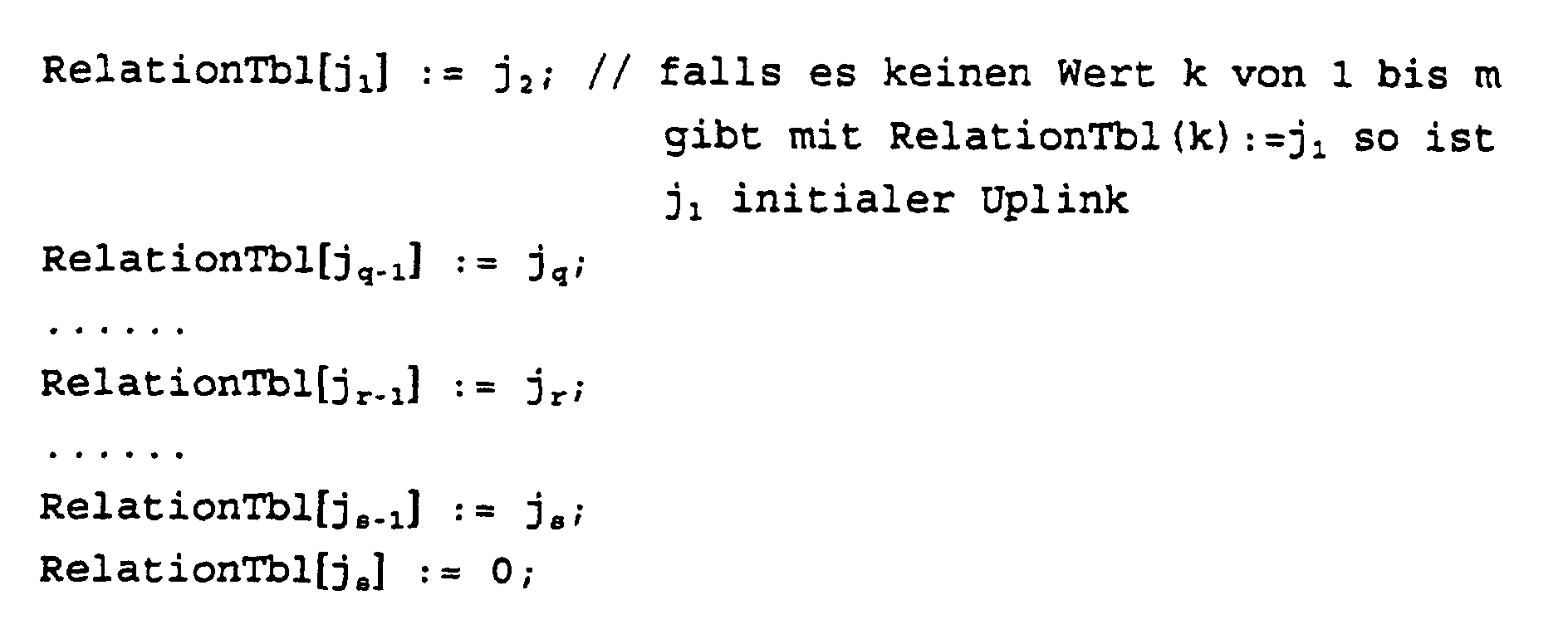


Angenommen der zu ersetzende link-i entspricht jq-1 , so wird die Tabelle RelationTbl durchlaufen, bis man auf RelationTbl[js] := trifft. js kennzeichnet den einzusetzenden horizontalen Link.Assuming the link-i to be replaced corresponds to j q-1 , the table RelationTbl is run through until one encounters RelationTbl [j s ]: =. j s indicates the horizontal link to be used.
Es gibt für alle m Links des Graphen G1 eine Tabelle der Art: LinkLevelTbl[k]=niedrigster Hierarchielevel der beiden Begrenzungsknoten des Links k; für alle k=1,..,m. link-i ist durch jq-1 bezeichnet. Es wird die Tabelle RelationTbl ab RelationTbl [ jq-1] durchlaufen, um von einem Link zum nächsten Link zu kommen und es wird dabei stets CurrentNodeLevel mit den Eintragungen in LinkLevelTbl verglichen. Angenommen, der Wert von CurrentNodeLevel sei gleich dem Wert von Link-LevelTbl[jr-1], so identifiziert jr-1 den gesuchten Link, welcher link-i ersetzen soll.There is a table of the type for all m links of the graph G1: LinkLevelTbl [k] = lowest hierarchical level of the two delimitation nodes of the link k; for all k = 1, .., m. link-i is denoted by j q-1 . The table RelationTbl from RelationTbl [j q-1 ] is run through in order to get from one link to the next link and currentNodeLevel is always compared with the entries in LinkLevelTbl. Assuming that the value of CurrentNodeLevel is equal to the value of Link-LevelTbl [j r-1 ], j r-1 identifies the searched link, which should replace link-i.
Aus der Folge F3 bilde man eine Folge F4 z.B. wie folgt:

Aus F4 bilde man eine Sequenz von DTLs, indem man die Folge F3 hinter jedem Uplink zerstückelt und aus jeder so erzeugten Teilfolge ein DTL Informationselement von PNNI-Protokoll-gerechter Syntax bildet - womit die erfindungsgemäße Aufgabe für den Ausgangsknoten S vollkommen beschrieben ist.From F4 one build a sequence of DTLs by following the sequence F3 dismembered behind each uplink and from each so generated Partial sequence of a DTL information element from PNNI protocol-compliant Syntax forms - what the task according to the invention is completely described for the output node S.
Erfindungsgemäß kann die Einbeziehung einer Schleife (im Sinne des erfindungsgemäßen Verfahrens ein Umweg über ein oder mehrere Peer Groups mit Rückkehr zu einer bereits passierten Peer Group an einem noch nicht passierten Wiedereintrittsknoten) auch beim Wiederauffüllen der Informationselemente der Leitweginformation bei Ankunft der Verbindungsaufbaumeldung in einem zu passierenden physikalischen Vermittlungsknoten (Transitknoten) erfolgen. Dies wird im folgenden anhand des Eintreffens einer Verbindungsaufbaumeldung im ersten physikalischen Vermittlungsknoten einer hierarchisch niedrigsten Peer Group verdeutlicht:According to the invention, the inclusion of a loop (in For the purposes of the method according to the invention, a detour via or several peer groups returning to one that has already passed Peer group at a not yet re-entry node) also when refilling the information elements the route information when the connection setup message arrives in a physical switching node to be passed (Transit node). This is the following based on the arrival of a connection establishment message in the first physical switching nodes one hierarchical lowest peer group clarifies:
Wenn beim Weiterleiten einer Verbindungsaufbaumeldung die momentane hierarchisch niedrigste Peer Group verlassen wird, so muß zuvor das diesbezügliche, stack-oberste DTL entfernt werden. Wird gar ein gewisser Hierarchiebereich verlassen, so müssen zuvor all jene stack-obersten Informationselemente DTL entfernt werden, welche Routenabschnitte durch die jeweiligen Peer Groups des zu verlassenden Hierarchiebereichs enthalten. Wenn beim Weiterleiten einer Verbindungsaufbaumeldung eine hierarchisch niedrigste Peer Group neu betreten wird, so müssen neue Routenabschnitte ermittelt und neue diesbezügliche DTLs gebildet werden. Die Zeiger in den einzelnen DTLs müssen stets so gesetzt bzw. vorgerückt werden, daß beim Empfang einer Verbindungsaufbaumeldung die Zeiger aller empfangenen DTLs je auf ein Knoten-Link-Paar deuten, welches entweder den empfangenden physikalische, hierarchisch niedrigste Knoten oder aber einen seiner ancestor nodes beinhaltet. If, when forwarding a connection setup message, the current hierarchically lowest peer group is left, so the relevant stack-top DTL must be removed beforehand. If a certain hierarchy area is left, so must first have all those stack-top information elements DTL which route sections are removed by the respective Contain peer groups of the hierarchy area to be left. If, when forwarding a connection setup message, a hierarchically lowest peer group is re-entered, so new route sections have to be determined and new ones related to this DTLs are formed. The pointers in the individual DTLs must always be set or advanced so that the Receive a connection establishment message everyone's pointers received DTLs each point to a node-link pair, which either the receiving physical, hierarchically lowest Contains nodes or one of its ancestor nodes.
Der Grenzknoten (S'), als Eintrittsknoten in eine weitere Peer Group bestimmt einen neuen besten Routenabschnitt bis hin zu einem Zielknoten D'. Der Zielknoten D' ist dem Knoten-Link-Paar zu entnehmen, welches dem Knoten-Link-Paar im stack-obersten der empfangenen DTLs nachfolgt, auf welches der diesbezügliche Zeiger zeigt.The boundary node (S '), as an entry node in another Peer Group determines a new best route section up towards a destination node D '. The destination node D 'is the node-link pair to see which of the node-link pair in the stack-top of the received DTLs follows which the relevant pointer shows.
Falls dies nicht möglich ist, weil der Zeiger bereits auf das letzte Knoten-Link-Paar deutet, so gilt selbiges bezogen auf das nächst-tiefer im stack befindliche DTL, usw. Es ist im Sinne der Erfindung, daß das PNNI-Protokoll vorschreibt, daß auch der empfangenen Link-Angabe, nämlich wie man zum Knoten Knoten D' kommt, voll und ganz entsprochen werden muß. Jeder Versuch etwa, noch besser dorthin zu gelangen, könnte zwar einen besseren Routenabschnitt erbringen, zugleich aber auch dazu führen, daß der vom Zielknoten D' repräsentierte Hierarchiebereich nicht am vorgesehenen Grenzknoten betreten wird, von wo aus die Fortsetzung des Verbindungsaufbaus in einer Sackgasse enden könnte. D.h. es wird zusätzlich zu D' auch noch der horizontale Link Link-to-D' bestimmt. Man entnimmt Link-to-D' dem Knoten-Link-Paar, welches dem jenigen DTL angehört, in welchem sich D' befindet und auf welches der diesbezügliche Zeiger beim Empfang des DTLs zeigt.If this is not possible because the pointer is already on the last node-link pair indicates, the same applies to the next lower DTL in the stack, etc. It is in the Purpose of the invention that the PNNI protocol stipulates that also the received link information, namely how to get to the node Knot D 'is coming, must be fully complied with. Everyone For example, trying to get there even better could provide a better route section, but also at the same time cause the hierarchy area represented by the destination node D ' is not entered at the designated border node, from where the continuation of the connection establishment in one Dead end could end. That it becomes in addition to D ' the horizontal link link-to-d 'still determines. One removes Link-to-D 'the node-link pair that belongs to that DTL, in which D 'is located and to which of these Pointer shows when receiving the DTL.
Der Grenzknoten S', der beachtet, daß er für den vorliegenden Verbindungsaufbauwunsch nur ein Transitknoten ist und daß der empfangene DTL Kellerspeicher unvollständig ist, bildet daher von seinem eigenen Graphen G1 ausgehend einen eventuell reduzierten Graphen G1' wie folgt:The boundary node S ', which notes that it is for the present Connection establishment request is only a transit node and that received DTL cellar memory is incomplete, therefore forms starting from its own graph G1, a possibly reduced one Graph G1 'as follows:
Vom Graphen G1 werden alle Knoten - samt angrenzender Links - mit einer Hierarchieebene größer oder gleich der Hierarchieebene des Knoten D' entfernt, nicht aber D' selbst und auch nicht jene Uplinks, für die D' Upnode ist und dabei dem Link-to-D' zugeordnet sind. D.h. für alle Uplinks, welche D' als Upnode haben, mache man folgende Prüfung: Graph G1 shows all nodes - including adjacent links - with a hierarchy level greater than or equal to the hierarchy level of the node D 'removed, but not D' itself and also not those uplinks for which D 'Upnode is and the link-to-D' assigned. That for all uplinks, which D 'as Upnode, do the following test:
Wie in Teilaufgabe-1 ist einem Uplink ein jq-1 zuordenbar. Man durchlaufe die Tabelle RelationTbl ausgehend von Relation-Tb1[jq-1] bis man auf einen Eintrag RelationTbl[js] := trifft. Falls js dem Link-to-D' entspricht, so darf der Uplink im Graphen G1' verbleiben. Andernfalls wird er entfernt.As in subtask-1, an uplink can be assigned a j q-1 . Run through the table RelationTbl starting from Relation-Tb1 [j q-1 ] until you find an entry RelationTbl [j s ]: =. If j s corresponds to the link-to-D ', the uplink may remain in the graph G1'. Otherwise it will be removed.
Von G1' ausgehend werden die Graphen G2' und G3' gebildet, ganz analog wie der Ausgangsknoten S die Graphen G2' und G3' gebildet hat, und wie oben beschrieben ein DTL-stack bestimmt wird, wobei S' die Funktion von S und D' die Funktion von D übernimmt (siehe obige Beschreibung).Starting from G1 ', the graphs G2' and G3 'are formed, quite analogous to the output node S the graphs G2 'and G3' has formed, and determined a DTL stack as described above where S 'is the function of S and D' is the function of D takes over (see description above).
Vom resultierenden DTL-Kellerspeicher werden sämtliche DTLs mit Ausnahme des allerletzten (welches D' enthält) übernommen und damit der weiterzuleitende DTL- Kellerspeicher vervollständigt.All DTLs become from the resulting DTL basement storage with the exception of the very last one (which contains D ') and thus completes the forwarding DTL cellar storage.
Eine Einbeziehung von oben genannten Schleifen beim erfindungsgemäßen Verfahren erfordert, daß Verbindungsleitungen existieren, die mit unterschiedlichen Grenz-Vermittlungsknoten des ersten Teilnetzes bzw. unterschiedlichen Vertretern der Teilnetze höherer Hierarchieebene verbunden sind; erst damit ergeben sich alternative Leitwege.Inclusion of the above-mentioned loops in the invention Procedure requires connecting lines exist with different border switching nodes of the first subnet or different representatives the subnets are connected at higher hierarchical levels; first this leads to alternative routes.
Konnten wirtschaftlichere Alternativen zur schleifenlosen Leitwegen für eine Verbindung mit den gewünschten Eigenschaften ermittelt werden, werden Leitweginformationen, die Angaben über die überprüften Verbindungsleitungen enthalten, erzeugt. Beim erfindungsgemäßen Verfahren ist kein Wissen zur Netztopologie der weiteren Teilnetze (Peer Groups )- also außerhalb der des eigenen Zweiges der Hierarchie im Vermittlungsknoten, der die Leitwegbildung vornimmt, erforderlich. Wesentlich ist jedoch, daß zumindest zwei Verbindungsleitungen von unterschiedlichen Grenz-Vermittlungsknoten des ersten Teilnetz zu zumindest einem weiteren Teilnetz vorliegen. Could be more economical alternatives to the loopless Routes for a connection with the desired properties route information are determined, the information included over the checked connecting lines. In the method according to the invention there is no knowledge of Network topology of the other subnetworks (peer groups) - that is outside of the own branch of the hierarchy in the switching node, routing is required. It is essential, however, that at least two connecting lines of different border switching nodes of the first subnet to at least one further subnet.
Das erfindungsgemäße Verfahren kann im Ausgangs-Vermittlungsknoten realisiert werden, wenn der Ausgangs-Vermittlungsknoten und der Ziel-Vermittlungsknoten dem gleichen Teilnetz angehören und die Leitweginformationen mit einer oder mehreren Schleifen zu weitern Teilnetzen gebildet werden. Dabei kann durch den Ausgangs-Vermittlungsknoten für einen Verbindungsaufbau erstmalig die Bildung von Leitweginformationen für eine Verbindungsaufbaumeldung (setup) vorgenommen werden. A1-ternativ ist es möglich, daß der die Leitweginformation im Sinne des erfindungsgemäßen Verfahrens bildende Ausgangs-Vermittlungsknoten selbst ein Transit-Kommunikationssystem ist, so daß die Verbindungsaufbaumeldung (setup) empfangen wird und die darin enthaltene Leitweginformationen weiterverarbeitet und für den folgenden Leitweg zum Ziel-Vermittlungsknoten weitergebildet wird.The method according to the invention can be in the output switching node be realized when the output switching node and the destination switching node belong to the same subnet and the route information with one or more Loops to further subnets are formed. It can through the exit switch for connection establishment for the first time the creation of routing information for a connection setup message (setup). A1-tively it is possible that the routing information in the Output switching nodes forming the sense of the method according to the invention itself is a transit communication system, so that the connection setup message (setup) is received and further processes the route information contained therein and for the following route to the destination switching node is trained.
Gehören der Ausgangs-Vermittlungsknoten einem ersten Teilnetz und der Ziel-Vermittlungsknoten einem weiteren Teilnetz an, können ebenfalls erkennbare Engpässe vermieden werden, indem Schleifen in den Leitweg einbezogen werden.The output switching nodes belong to a first subnet and the destination switching node to another subnet, Identifiable bottlenecks can also be avoided by Loops should be included in the route.
Es ist möglich, Verbindungsleitungen zwischen Teilnetzen vorgebbarer höherer Ordnung nicht in die Leitwegsuche durch Nutzung eines gemeinsamen Zuordnungszeichens für mehrere Verbindungsleitungen einzubeziehen. Dies bedeutet, daß die Einbeziehung weiterer Teilnetze in die Leitwegsuche auf bestimmte Bereiche der Hierarchie des ATM-Kommunikationsnetzes beschränkt wird. Geht man davon aus, daß Teilnetze anhand von geographischen Kriterien strukturiert werden, werden damit Leitwegsuchen über geographisch weit entfernten Teilnetze unterbunden, wodurch eine Obergrenze für den Ressourcen- und damit den wirtschaftlichen Aufwand für einen Verbindungsaufbau vorgegeben werden kann.It is possible to specify connecting lines between subnetworks higher order not in the route search through use a common assignment symbol for several connecting lines included. This means inclusion further subnets in the route search on certain Areas of the hierarchy of the ATM communication network are limited becomes. Assuming that subnetworks are based on geographic criteria are structured with it Prevents route searches via geographically distant subnets, creating an upper limit for the resource and thus the economic effort for establishing a connection can be specified.
Gemäß einer weiteren vorteilhaften Ausgestaltung des erfindungsgemäßen Verfahrens kann die Einbeziehung von weiteren Teilnetzen derart erfolgen, daß ein Teilnetz mehrmals verlassen wird oder auch Schleifen bei weiteren Teilnetzen zugelassen werden, ohne die ein Zustandekommen der Verbindung nicht mit den gleichen Bedingungen möglich wäre. Durch diese Ausweitung der Prüfung auf das Vorhandensein von Verbindungsleitungen können auch Verbindungen realisiert werden, bei denen die Leitwegressourcen und Vermittlungskapazitäten des ersten Teilnetzes stark eingeschränkt sind.According to a further advantageous embodiment of the invention Procedures can include further Subnets are made in such a way that they leave a subnet several times is permitted or grinding is also permitted in other subnets without the connection being established would not be possible with the same conditions. Through this Extension of the test for the presence of connecting lines connections can also be realized at to whom the routing resources and switching capacities of the first subnet are severely restricted.
Weitere vorteilhafte Ausbildungen des erfindungsgemäßen Verfahrens sind den übrigen untergeordneten Ansprüchen zu entnehmen.Further advantageous developments of the method according to the invention can be found in the other subordinate claims.
Anhand der Figuren 1 bis 3 wird beispielhaft die Bildung der Leitweginformation in Vermittlungsknoten eines ATM-Kommunikationsnetzes näher erläutert. Dabei zeigen die Figuren 1 bis 3 ein und dasselbe ATM-Kommunikationsnetz für eine Leitwegsuche und Bildung von Leitweginformation, jedoch von unterschiedlichen Vermittlungsknoten aus gesehen.
- Figur 1
- zeigt das ATM-Kommunikationsnetz aus der Sicht des Ausgangsvermittlungsknotens A.1,
- Figur 2
- zeigt das ATM-Kommunikationsnetz aus der Sicht des Transitvermittlungsknotens B.2 und
- Figur 3
- zeigt das ATM-Kommunikationsnetz aus der Sicht des weiteren Transit-Vermittlungsknotens C.1.
- Figure 1
- shows the ATM communication network from the point of view of the exit switching node A.1,
- Figure 2
- shows the ATM communication network from the point of view of the transit switching node B.2 and
- Figure 3
- shows the ATM communication network from the point of view of the further transit switching node C.1.
Das Hierarchiebild des ATM-Kommunikationsnetzes zeigt beispielhaft drei Teilnetze TA,TB,TC. Das erste Teilnetz TA umfaßt die physikalischen Knoten A.1..6. Für den zu betrachtenden Verbindungsaufbau ist der Knoten A.1 der Ausgangsvermittlungsknoten und der Knoten A.6 der Zielvermittlungsknoten. Diese Ausgangs- und Zielknoten müssen sich jedoch nicht in der gleichen Peer Group (Teilnetz) befinden, auch kann die Inanspruchnahme von Umwegen erst durch einen Transitknoten erfolgen. Ein weiteres Teilnetz TB umfaßt die Knoten B.1..5 und ein zusätzliches weiteres Teilnetz TC die Knoten C.1..4. Die Teilnetze TA, TB (peer groups der niedrigsten Hierarchieebene) sind auf einer höheren Hierarchieebene zu einer Netzgruppe TAB (peer group höherer Hierarchieebene) zusammengefaßt und werden jeweils durch eine logischen Knoten A, B repräsentiert. Auf einer wiederum höheren Hierarchieebene ist diese Netzgruppe TAB (peer group) mit dem weiteren zusätzlichen Teilnetz TC zu einer Netzgruppe TABC zusammengefaßt, wobei ein logischer Knoten AB die Netzgruppe höherer Hierarchieebne TAB und ein logischer Knoten C, das weitere zusätzliche Teilnetz TC repräsentieren.The hierarchy of the ATM communication network shows an example three subnets TA, TB, TC. The first subnet includes TA the physical nodes A.1..6. For the one to be considered Connection establishment is the node A.1 the output switching node and node A.6 the destination switching node. However, these starting and destination nodes must be different are not in the same peer group (subnet), too the use of detours can only be made through a transit node respectively. Another subnet TB includes Node B.1..5 and an additional further subnet TC Node C.1..4. The subnetworks TA, TB (peer groups of the lowest Hierarchy level) are at a higher hierarchy level to a network group TAB (peer group higher hierarchical level) are summarized and are each represented by a logical Node A, B represents. At a higher hierarchical level is this network group TAB (peer group) with the other additional subnet TC combined into a network group TABC, where a logical node AB is the network group higher hierarchy level TAB and a logical node C that represent further additional subnetwork TC.
Die Knoten sind untereinander durch physikalische Verbindungsleitungen (physikal links) verbunden. Links pb1,2,3 und pc1,2 zwischen Knoten verschiedener Teilnetze sind zusätzliche Informationen zugeordnet.The nodes are interconnected by physical connection lines (physically left) connected. Left pb1,2,3 and pc1,2 between nodes of different subnets are additional Associated information.
- Anfangsbuchstabe
- p= physical link,
h=horizontal link,
u= initialer Uplink,
U=induzierter Uplink
- First letter
- p = physical link,
h = horizontal link,
u = initial uplink,
U = induced uplink
Die Knoten, in denen nach den Figuren 1 bis 3 die Leitweginformation gebildet wird, sehen nur jeweils die dick umrandeten Peer Groups (die im jeweiligen Knoten gespeicherte Wissensbasis umfaßt Angaben über diese Peer Groups). Statt der physikalischen Verbindungsleitungen, welche aus der hierarchisch niedrigsten Peer Group herausführen, sehen sie die diesbezüglich zugeordneten Uplinks. Nur die jeweiligen Grenzknoten selbst wissen um diese Zuordnung, teilen dieses Wissen aber nicht den übrigen Knoten der Peer Group mit. The nodes in which the route information according to FIGS. 1 to 3 is formed, only see those with thick borders Peer Groups (the knowledge base stored in the respective node includes information about these peer groups). Instead of the physical connecting lines, which come from the hierarchical lowest peer group, they see the related uplinks. Only the respective border nodes even know about this assignment, share this knowledge but not the other nodes of the peer group.
Gesucht ist eine Route vom Ausgangsknoten A.1 zum Zielknoten A.6. Blockiert sind die Verbindungsleitungen pa5, pa6, die eine direkte Route vom Ausgangsknoten A.1 zum Zielknoten A.6 zulassen würden. Dick eingezeichnet ist der physikalische Weg, den der Verbindungsaufbau nehmen sollte.We are looking for a route from the starting node A.1 to the destination node A.6. The connecting lines pa5, pa6 are blocked a direct route from the output node A.1 to the destination node A.6 would allow. The physical one is shown in bold Path that the connection establishment should take.
Im Ausgangsknoten A.1 sei der Graph G1, in Form einer Liste
von Links samt deren Begrenzungsknoten gespeichert, d.h.
G1(A.1) - siehe Figur 1:
(pa2 : A.2 , A.1), (pa3 : A.3 , A.1), (pa4 : A.4 , A.5), (pa5
: A.5 , A.1), (pa6 : A.6 , A.5),
(ub1: A.2 , B), (ub2: A.3 , B), (ub3: A.4 , B),
(uc1 : A.5, C), (uc2 : A.6 , C).
(hb1 : B , A), (hb2 : B , A), (hb3 : B , A),
(Uc1 : A, C), (Uc2 : A , C),
(hc1 C , AB), (hc2 : C , AB),In the output node A.1 let the graph G1 be stored in the form of a list of links including their delimiting nodes, ie G1 (A.1) - see FIG. 1:
(pa2: A.2, A.1), (pa3: A.3, A.1), (pa4: A.4, A.5), (pa5: A.5, A.1), (pa6 : A.6, A.5),
(ub1: A.2, B), (ub2: A.3, B), (ub3: A.4, B),
(uc1: A.5, C), (uc2: A.6, C).
(hb1: B, A), (hb2: B, A), (hb3: B, A),
(Uc1: A, C), (Uc2: A, C),
(hc1 C, AB), (hc2: C, AB),
Es werden die blockierten Leitungen entfernt, und zwar (pa5 :
A.5 , A.1), (pa6 : A.6 , A.5), und
es wird der Graph G2(A.1) bestimmt:
(pa2 : A.2 , A.1), (pa3 : A.3 , A.1), (pa4 : A.4 , A.5),
(ub1: A.2 , B), (ub2: A.3 , B), (ub3: A.4 , B),
(uc1 : A.5, C), (uc2 : A.6 , C).
(hb1 : B , A), (hb2 : B , A), (hb3 : B , A),
(Uc1 : A, C), (Uc2 : A , C),
(hc1 : C , AB), (hc2 : C , AB),The blocked lines are removed, namely (pa5:
A.5, A.1), (pa6: A.6, A.5), and
the graph G2 (A.1) is determined:
(pa2: A.2, A.1), (pa3: A.3, A.1), (pa4: A.4, A.5), (ub1: A.2, B), (ub2: A .3, B), (ub3: A.4, B),
(uc1: A.5, C), (uc2: A.6, C).
(hb1: B, A), (hb2: B, A), (hb3: B, A),
(Uc1: A, C), (Uc2: A, C),
(hc1: C, AB), (hc2: C, AB),
Alle ancestor nodes samt angrenzenden Leitungen werden entfert,
nämlich
(hb1 : B , A), (hb2 : B , A), (hb3 : B , A),
(Uc1 : A, C), (Uc2 : A , C),
(hc1 : C , AB), (hc2 : C , AB),
und damit Graph G3(A.1) bestimmt:
(pa2 : A.2 , A.1), (pa3 : A.3 , A.1), (pa4 : A.4 , A.5),
(ub1: A.2 , B), (ub2: A.3 , B), (ub3: A.4 , B),
(uc1 : A.5, C), (uc2 : A.6 , C).All ancestor nodes including adjacent lines are removed, namely
(hb1: B, A), (hb2: B, A), (hb3: B, A),
(Uc1: A, C), (Uc2: A, C),
(hc1: C, AB), (hc2: C, AB),
and thus graph G3 (A.1) determines:
(pa2: A.2, A.1), (pa3: A.3, A.1), (pa4: A.4, A.5), (ub1: A.2, B), (ub2: A .3, B), (ub3: A.4, B),
(uc1: A.5, C), (uc2: A.6, C).
Die Anwendung des Dijkstra-Routing-Algorithmus erbringt die
Folge F1:
Destination Node D = A.6, uc2,C, uc1,A.5, pa4, A.4, ub3, B,
ub1, A.2, pa2, A.1=Source Node S.The application of the Dijkstra routing algorithm results in the sequence F1:
Destination Node D = A.6, uc2, C, uc1, A.5, pa4, A.4, ub3, B, ub1, A.2, pa2, A.1 = Source Node S.
Die umgekehrte Reihenfolge = F2 lautet: Source Node S=A.1, pa2,A.2, ub1, B, ub3, A.4, pa4, A.5, uc1, C,uc2, A.6 = Destination Node D.The reverse order = F2 is: Source Node S = A.1, pa2, A.2, ub1, B, ub3, A.4, pa4, A.5, uc1, C, uc2, A.6 = Destination Node D.
Die Folge F3 wird bestimmt:
A.1, pa2, A.2, ub1, B, hb3,A, Uc1, C, hc2, AB.Sequence F3 is determined:
A.1, pa2, A.2, ub1, B, hb3, A, Uc1, C, hc2, AB.
Die Folge F4 wird bestimmt:
A.1, pa2, A.2, ub1, A, hb1, B,hb3,A, Uc1,AB, hc1, C, hc2, AB.Sequence F4 is determined:
A.1, pa2, A.2, ub1, A, hb1, B, hb3, A, Uc1, AB, hc1, C, hc2, AB.
Daraus werden die Informationselement des DTL-Kellerspeichers
abgeleitet. Die Folge F4 wird nach jedem Uplink zerteilt und
man bildet aus jeder der entstandenen Teilfolge ein Informationselement
DTL, wie sie zum nächsten physikalischen Knoten
gesendet werden. Der Zeiger zeigt auf das x-te geklammerte
Knoten-Link-Paar.
Der Transit-Knoten B.2 empfängt folgende Leitweginformation
ri:
Knoten B.2 hat das von ihm sichtbare Netz als Graph G1(B.2)
gespeichert - siehe Figur 2 dick umrahmt:
(pb4: B.1,B.2), (pb5: B.1,B.5), (pb6: B.4,B.5), (pb7 :
B.3,B.4), (pb8: B.2,B.3),
(ua1: B.2, A), (ua2: B.3, A), (ua3: B.4, A),
(hb1 : B , A), (hb2 : B , A), (hb3 : B , A),
(Uc1 : A, C), (Uc2 : A , C),
(hc1 : C , AB), (hc2 : C , AB).Node B.2 has saved the network it sees as graph G1 (B.2) - see Figure 2 with a thick frame:
(pb4: B.1, B.2), (pb5: B.1, B.5), (pb6: B.4, B.5), (pb7:
B.3, B.4), (pb8: B.2, B.3),
(ua1: B.2, A), (ua2: B.3, A), (ua3: B.4, A),
(hb1: B, A), (hb2: B, A), (hb3: B, A),
(Uc1: A, C), (Uc2: A, C),
(hc1: C, AB), (hc2: C, AB).
Weil es sich um einen Transit-Verkehr handelt, wird G1'(B.2)
gebildet, indem
zunächst D'(B.2) und Link-to-D'(B.2) bestimmt wird:
D' (B.2) = A
Link-to-D'(B.2) = hb3.Because it is a transit traffic, G1 '(B.2) is formed by
first D '(B.2) and Link-to-D' (B.2) is determined:
D '(B.2) = A
Link-to-D '(B.2) = hb3.
Im Transit-Knoten werden vom Graphen G1(B.2) alle Knoten vom
Hierarchielevel größer-gleich des logischen Knotens A, sowie
die diesbezüglich angrenzenden Links entfernt, ausgenommen
jedoch D'(B.2) = A selbst und ausgenommen jene Uplinks für
die A Upnode ist und mit Link-to-D'(B.2)=hb3 korreliert sind.
Es entsteht der Graph G1'(B.2):
(pb4: B.1,B.2), (pb5: B.1,B.5), (pb6: B.4,B.5), (pb7:
B.3,B.4), (pb8: B.2,B.3),
(ua3: B.4, A)In the transit node, graph G1 (B.2) removes all nodes from the hierarchical level greater than or equal to logical node A, as well as the related links, except for D '(B.2) = A itself and excluding those uplinks for A is upnode and correlated with link-to-D '(B.2) = hb3. The graph G1 '(B.2) is created:
(pb4: B.1, B.2), (pb5: B.1, B.5), (pb6: B.4, B.5), (pb7:
B.3, B.4), (pb8: B.2, B.3),
(ua3: B.4, A)
Da keine Blockierungen dem Transitknoten B.1 bekannt sind,
gilt Graph G1'(B.2) Graph G2'(B.2)
Da keine ancestor nodes des B.1 weiter davon entfernt werden
können, gilt G1'(B.2) = G2' (B.2) = G3'(B.2).Since no blocks are known to transit node B.1, graph G1 '(B.2) graph G2' (B.2) applies
Since no ancestor nodes of B.1 can be removed from it, G1 '(B.2) = G2' (B.2) = G3 '(B.2) applies.
Der angewendet Dijkstra-Routing-Algorithmus ergibt eine Folge
F1:
D'(B.2) =A, ua3, B.4, pb7, B.3, pb8, B.2=S'(B.2)The Dijkstra routing algorithm applied results in a sequence F1:
D '(B.2) = A, ua3, B.4, pb7, B.3, pb8, B.2 = S' (B.2)
Daraus ergibt sich in umgekehrter Reihenfolge F2:
S'(B.2) =B.2, pb8, B.3, pb7, B.4, ua3, A=D'(B.2) In reverse order, this results in F2:
S '(B.2) = B.2, pb8, B.3, pb7, B.4, ua3, A = D' (B.2)
Die Operation zur Bildung von F3 ergeben keine Veränderungen,
d.h. Folge F2 = Folge F3.
Aus Folge F3 wird Folge F4 gebildet:
S'(B.2) =B.2, pb8, B.3, pb7, B.4, ua3, B, hb3, A=D'(B.2)The operation to form F3 does not result in any changes, ie sequence F2 = sequence F3.
Sequence F4 is formed from sequence F3:
S '(B.2) = B.2, pb8, B.3, pb7, B.4, ua3, B, hb3, A = D' (B.2)
Aus Folge F4 werden die Informationselemente DTLs der Leitweginformation
ri gebildet:
Vom Eintrittsknoten B.2 zum weiteren Knoten B.3 im weiteren
Teilnetz TB wird somit folgende Leitweginformation ri im DTL-Kellerspeicher-Format
geschickt:
(B.2, pb8), (B.3, pb7), (B.4, ua3), Zeiger=2
(A, hb1), (B, hb3), (A , , Uc1), Zeiger=2
(AB, hc1), (C, hc2), (AB,x'00 00 00 00), Zeiger=1
(B.2, pb8), (B.3, pb7), (B.4, ua3), pointer = 2
(A, hb1), (B, hb3), (A,, Uc1), pointer = 2
(AB, hc1), (C, hc2), (AB, x'00 00 00 00), pointer = 1
Tätigkeit des Transit-Knotens A.4 im ersten Teilnetz TA:
Der Knoten A.4 empfängt folgende Leitweginformation ri:
Knoten A.4 hat das von ihm sichtbare Netz als Graph G1(A.4) gespeichert, welcher mit dem vom Ausgangsknoten A.1 gespeicherten Graphen G1(A.1) übereinstimmt, siehe oben und siehe Figur 1 (dick umrandet).Node A.4 has the network it sees as graph G1 (A.4) stored, which with the stored from the output node A.1 Graph G1 (A.1) matches, see above and see Figure 1 (thick border).
Weil es sich um einen Transit-Verkehr handelt wird G1'(A.4)
gebildet, indem
zunächst D'(A.4) und Link-to-D'(A.4) bestimmt wird:
D' (A.4) = C
Link-to-D' (A.4) = hc1.
Vom Graphen G1(A.4) werden alle Knoten vom Hierarchielevel
größer-gleich dem Hierarchielevel von D'(A.4) = C, sowie die
diesbezüglich angrenzenden Links entfert, jedoch ausgenommen
D'(A.4) = C selbst und ausgenommen jene Uplinks für die
D'(A.4) C Upnode ist und mit Link-to-D'(A.4)=hc1 korreliert
sind.Because it is a transit traffic, G1 '(A.4) is formed by
first D '(A.4) and Link-to-D' (A.4) is determined:
D '(A.4) = C
Link-to-D '(A.4) = hc1.
From graph G1 (A.4) all nodes of the hierarchy level greater than or equal to the hierarchy level of D '(A.4) = C, as well as the related links are removed, except for D' (A.4) = C itself and excluded those uplinks for which D '(A.4) C is upnode and are correlated with Link-to-D' (A.4) = hc1.
Es entsteht Graph G1'(A.4):
(pa2 : A.2 , A.1), (pa3 : A.3 , A.1), (pa4 : A.4 , A.5), (pa5
: A.5 , A.1), (pa6 : A.6 , A.5),
(ub1: A.2 , B), (ub2: A.3 , B), (ub3: A.4 , B),
(uc1 : A.5, C),
(hb1 : B , A), (hb2 : B , A), (hb3 : B , A),
(Uc1 : A, C)The result is graph G1 '(A.4):
(pa2: A.2, A.1), (pa3: A.3, A.1), (pa4: A.4, A.5), (pa5: A.5, A.1), (pa6 : A.6, A.5),
(ub1: A.2, B), (ub2: A.3, B), (ub3: A.4, B),
(uc1: A.5, C),
(hb1: B, A), (hb2: B, A), (hb3: B, A),
(Uc1: A, C)
Die blockierten Links werden entfernt und es ergibt sich daraus
Graph G2'(A.4) :
(pa2 : A.2 , A.1), (pa3 : A.3 , A.1), (pa4 : A.4 , A.5),
(ub1: A.2 , B), (ub2: A.3 , B), (ub3: A.4 , B),
(uc1 A.5, C),
(hb1 : B , A), (hb2 : B , A), (hb3 : B , A),
(Uc1 : A, C)The blocked links are removed and the result is graph G2 '(A.4):
(pa2: A.2, A.1), (pa3: A.3, A.1), (pa4: A.4, A.5),
(ub1: A.2, B), (ub2: A.3, B), (ub3: A.4, B),
(uc1 A.5, C),
(hb1: B, A), (hb2: B, A), (hb3: B, A),
(Uc1: A, C)
Sind davon alle noch enthaltenen ancestor nodes samt den
daran angrenzenden Verbindungsleitungen entfernt, so ergibt
sich Graph G3'(A.4):
(pa2 : A.2 , A.1), (pa3 : A.3 , A.1), (pa4 : A.4 , A.5),
(ub1: A.2 , B), (ub2: A.3 , B), (ub3: A.4 , B),
(uc1 : A.5, C) .If all of the ancestor nodes that are still present, including the connecting lines adjacent to them, are removed, the result is graph G3 '(A.4):
(pa2: A.2, A.1), (pa3: A.3, A.1), (pa4: A.4, A.5),
(ub1: A.2, B), (ub2: A.3, B), (ub3: A.4, B),
(uc1: A.5, C).
Per Dijkstra-Routing-Algorithmus wird darin als beste Route
vom Transitknoten A.4 zum Vertreter C des zusätzlichen weiteren
Teilnetzes TC die folgende Folge F1 ermittelt:
D'(A.4)=C, uc1, A.5, pa4, A.4= S'(A.4)
Durch Umkehrung der Reihenfolge ergibt sich die Folge F2:
S'(A.4)= A.4, pa4, A.5, uc1, C=D'(A.4) Using Dijkstra routing algorithm, the following route F1 is determined as the best route from transit node A.4 to representative C of the additional further subnetwork TC:
D '(A.4) = C, uc1, A.5, pa4, A.4 = S' (A.4)
Reversing the order results in F2:
S '(A.4) = A.4, pa4, A.5, uc1, C = D' (A.4)
Da die Folge F2 hinsichtlich Hierarchieebene der auftretenden Knoten niemals absteigend ist, so ergeben die Operationen zur Bildung der Folge F3 keine Änderungen: F3= F2.Since the sequence F2 with regard to the hierarchical level of the occurring Knots is never descending, so the operations result in Formation of sequence F3 no changes: F3 = F2.
Aus der Folge F3 wird die Folge F4 gewonnen, nämlich:
S'(A.4)= A.4, pa4, A.5, uc1,AB, hc1, C=D'(A.4)Sequence F4 is obtained from sequence F3, namely:
S '(A.4) = A.4, pa4, A.5, uc1, AB, hc1, C = D' (A.4)
Aus der Folge F4 die folgenden Informationselement DTLs der
Leitweginformation ri abgeleitet:
Vom Transitknoten A.4 zum Knoten A.5 wird somit folgender
DTL-Kellerspeicherinhalt übermittelt:
Tätigkeit des Transit-Knotens C.1 im zusätzlichen weiteren
Teilnetz TC:
Der Knoten C.1 empfängt folgende Leitweginformation ri:
Der Knoten C.1 hat das von ihm sichtbare Netz als Graph
G1(C.1) gespeichert, siehe Figur 3:
(pc3: C.1, C.2), (pc4: C.2, C.3), (pc5: C.3, C.4), (pc6: C.1,
C.4),
(uab1: C.1, AB), (uab2: C.4, AB)
(hc1: C, AB), (Hc2: C, AB) The node C.1 has saved the network it sees as a graph G1 (C.1), see FIG. 3:
(pc3: C.1, C.2), (pc4: C.2, C.3), (pc5: C.3, C.4), (pc6: C.1, C.4),
(uab1: C.1, AB), (uab2: C.4, AB)
(hc1: C, AB), (Hc2: C, AB)
Weil es sich um einen Transit-Verkehr handelt wird G1'(C.1)
gebildet, indem zunächst D'(C.1) und Link-to-D'(C.1) bestimmt
wird:
D'(C.1) = AB
Link-to-D'(C.1) = hc2.
Von Graph G1(C.1) werden alle Knoten von einer Hierarchieebene
größer-gleich der Hierarchieebene von D'(C.1) AB,
sowie die diesbezüglich angrenzenden Links entfernt, jedoch
ausgenommen D'(C.1) = C selbst und ausgenommen jene Uplinks
für die D'(C.1) = AB Upnode ist und mit Link-to-D'(C.1)=hc2
korreliert sind.
Es ergibt sich der Graph G1'(C.1):
(pc3: C.1, C.2), (pc4: C.2, C.3), (pc5: C.3, C.4), (pc6: C.1,
C.4),
(uab2: C.4, AB)Because it is a transit traffic, G1 '(C.1) is formed by first determining D' (C.1) and Link-to-D '(C.1):
D '(C.1) = AB
Link-to-D '(C.1) = hc2.
Graph G1 (C.1) removes all nodes from a hierarchy level greater than or equal to the hierarchy level of D '(C.1) AB, as well as the related links, except D' (C.1) = C itself and exempted those uplinks for which D '(C.1) = AB is upnode and are correlated with Link-to-D' (C.1) = hc2.
The graph G1 '(C.1) results:
(pc3: C.1, C.2), (pc4: C.2, C.3), (pc5: C.3, C.4), (pc6: C.1, C.4),
(uab2: C.4, AB)
Da der Knoten C.1 keine blockierten Verbindungsleitungen vorfindet
(diese befinden sich im ersten Teilnetz TA), ist
G1' (C.1) = G2' (C.1).
Weil sich davon keine ancestor nodes bezüglich Knoten C.1 zusätzlich
entfernen lassen ist:
G1' (C.1) = G2' (C.1) = G3' (C.1)Since the node C.1 does not find any blocked connecting lines (these are located in the first subnet TA)
G1 '(C.1) = G2' (C.1).
Because no ancestor nodes regarding node C.1 can be removed from it:
G1 '(C.1) = G2' (C.1) = G3 '(C.1)
Mit Hilfe des Dijkstra-Routing-Algorithmus wird de Knoten C.1
als beste Route die Folge F1 ermitteln:
D'(C.1)=AB, uab2, C.4, pc6, C.1=S'(C.1)With the help of the Dijkstra routing algorithm, node C.1 will determine the sequence F1 as the best route:
D '(C.1) = AB, uab2, C.4, pc6, C.1 = S' (C.1)
Durch Umkehrung der Reihenfolge ergibt sich Folge F2:
S'(C.1), pc6, C.4, uab2, AB=D'(C.1)Reversing the order results in F2:
S '(C.1), pc6, C.4, uab2, AB = D' (C.1)
Da die Folge F2 hinsichtlich der Hierarchieebene der auftretenden
Knoten niemals absteigend ist, so ergeben die Operationen
zur Bildung der Folge F3 keine Änderungen:
F3 = F2.Since the sequence F2 is never descending with regard to the hierarchical level of the nodes that occur, the operations for forming the sequence F3 do not result in any changes:
F3 = F2.
Aus der Folge F3 wird die Folge F4 gewonnen, nämlich:
S'(C.1)=C.1, pc6, C.4, uab2,C,hc2, AB=D'(C.1) Sequence F4 is obtained from sequence F3, namely:
S '(C.1) = C.1, pc6, C.4, uab2, C, hc2, AB = D' (C.1)
Aus der Folge F4 werden die folgenden Informationselemente
DTL der Leitweginformation ri abgeleitet:
Vom Knoten C.1 zum weiteren Knoten C.4 im zusätzlichen weiteren
Teilnetz TC wird somit folgender DTL-stack übermittelt:
Tätigkeit des Wiedereintritts-Knotens A.6 für den zweiten
Wiedereintritt ins erste Teilnetz TA:
Der Knoten A.6 empfängt folgende Leitweginformation ri:
The node A.6 receives the following routing information ri:
Insofern Knoten A.6 erkennt, daß das Ziel-Endgerät an ihm unmittelbar angeschlossen ist, sendet er die Verbindungsaufbaumeldung (setup) entlang der diesbezüglichen UNI-Schnittstelle (nicht mehr PNNI-Schnittstelle) zu diesem, wobei, UNI-Protokoll-gemäß, keine Informationselemente DTLs mitgegeben werden. Der Leitweg ist abgeschlossen.In this respect node A.6 recognizes that the target terminal is directly connected to it is connected, it sends the connection setup message (setup) along the relevant UNI interface (no longer PNNI interface) to this, whereby, according to UNI protocol, no information elements DTLs are given. The route is complete.
Claims (8)
- Method for forming routing information in an ATM communication network, comprising switching nodes (A.1..6, B.1..5, C.1..4), for a connection set-up message from a source switching node (A.1) to a destination switching node (A.6),in which method all the topology information is taken into account via connecting lines within that branch of the communication network hierarchy which starts from the switching node (A.1, B.2, B.4, A.4, A.5, C.1, C.4), which performs the formation of routing information, for the formation of routing information in the ascending direction with respect to the communication network hierarchy, characterized in that even advantageous routing loops are taken into account via one or more subnetworks (TB, TC, TAB, TABC) of any hierarchy level with different exit and re-entry switching nodes (A.2,A.4; A.5,A.6) in such a way that connecting lines (pb3, pc2) in the descending direction with respect to the communication network hierarchy are also included by the switching node (A.1, A.5) which forms routing information.the switching nodes (A.1..6, B.1..5, C.1..4) being assigned in each case to subnetworks (TA, TB, TC) and being networked to one another via connecting lines (pa1..6,pb1..8,pc1..6) and being unambiguously combined according to an ascending hierarchical order to form subnetworks (TAB) of a higher order, which subnetworks are further combined into subnetworks (TABC) of the next higher order, and
- Method according to Claim 1, characterized in that the switching nodes (A.1..6, B.1..5, C.1..4) operate in accordance with the principles of the private network node protocol (PNNI protocol).
- Method according to Claim 1 or 2, characterized in that the formation of routing information in the source switching node (A.1) includes the routing loops for a connection set-up message.
- Method according to Claim 1 or 2, characterized in that the formation of routing information in a transit switching node (A.5) includes the routing loops for a connection set-up message.
- Method according to one of Claims 1 to 4, in which the source switching node (A.1) and the destination switching node (A.6) belong to the same subnetwork (TA) and the routing information is formed including one or more loops to form further subnetworks (TB, TC).
- Method according to one of Claims 1 to 4, in which the source switching node (A.1) and the destination switching node (A.6) do not belong to the same subnetwork and the routing information is formed including one or more loops to form subnetworks of any hierarchy level during the course of the progression of the connection set-up.
- Method according to one of Claims 1 to 6, characterized in that connecting lines (pc1, pc2) between subnetworks (TA,TC) starting from a prescribable hierarchy level are not taken into account for the formation of the routing information which is subject to loops, in that a common assignment character is determined for a plurality of connecting lines.
- Method according to one of Claims 2 to 7, characterized in that the routing information is structured into information elements (DTL1..3) by the starting ATM switching node (VK1), one information element (DTL1..3) being formed for the first subnetwork (TA) and for each order of subnetworks (TAB,TABC) included in the route.
Priority Applications (12)
| Application Number | Priority Date | Filing Date | Title |
|---|---|---|---|
| EP95120259A EP0781007B1 (en) | 1995-12-21 | 1995-12-21 | Method for creating routing information in an ATM communications network |
| DE59510586T DE59510586D1 (en) | 1995-12-21 | 1995-12-21 | Method for forming routing information in an ATM communication network |
| EP96942349A EP0872090B1 (en) | 1995-12-21 | 1996-12-04 | Method of forming routing data |
| AT96942349T ATE235768T1 (en) | 1995-12-21 | 1996-12-04 | METHOD FOR FORMING ROUTING INFORMATION |
| PCT/EP1996/005423 WO1997023978A1 (en) | 1995-12-21 | 1996-12-04 | Method of forming routing data |
| CN96180090A CN1127831C (en) | 1995-12-21 | 1996-12-04 | Method for forming routing data |
| DE59610283T DE59610283D1 (en) | 1995-12-21 | 1996-12-04 | METHOD FOR MAKING ROUTE INFORMATION |
| US09/091,636 US6333918B1 (en) | 1995-12-21 | 1996-12-04 | Method of forming routing data |
| SG9611615A SG86989A1 (en) | 1995-12-21 | 1996-12-10 | Method for forming routing information in an atm communication network |
| US08/768,172 US5831982A (en) | 1995-12-21 | 1996-12-17 | Method for forming routing information in an ATM communication network |
| CNB961232838A CN1150723C (en) | 1995-12-21 | 1996-12-20 | Method for establishing route information in ATM communication network |
| HK98102648A HK1003553A1 (en) | 1995-12-21 | 1998-03-27 | Method for creating routing information in an atm communications network |
Applications Claiming Priority (1)
| Application Number | Priority Date | Filing Date | Title |
|---|---|---|---|
| EP95120259A EP0781007B1 (en) | 1995-12-21 | 1995-12-21 | Method for creating routing information in an ATM communications network |
Publications (2)
| Publication Number | Publication Date |
|---|---|
| EP0781007A1 EP0781007A1 (en) | 1997-06-25 |
| EP0781007B1 true EP0781007B1 (en) | 2003-03-12 |
Family
ID=8219907
Family Applications (2)
| Application Number | Title | Priority Date | Filing Date |
|---|---|---|---|
| EP95120259A Expired - Lifetime EP0781007B1 (en) | 1995-12-21 | 1995-12-21 | Method for creating routing information in an ATM communications network |
| EP96942349A Expired - Lifetime EP0872090B1 (en) | 1995-12-21 | 1996-12-04 | Method of forming routing data |
Family Applications After (1)
| Application Number | Title | Priority Date | Filing Date |
|---|---|---|---|
| EP96942349A Expired - Lifetime EP0872090B1 (en) | 1995-12-21 | 1996-12-04 | Method of forming routing data |
Country Status (8)
| Country | Link |
|---|---|
| US (2) | US6333918B1 (en) |
| EP (2) | EP0781007B1 (en) |
| CN (2) | CN1127831C (en) |
| AT (1) | ATE235768T1 (en) |
| DE (2) | DE59510586D1 (en) |
| HK (1) | HK1003553A1 (en) |
| SG (1) | SG86989A1 (en) |
| WO (1) | WO1997023978A1 (en) |
Families Citing this family (68)
| Publication number | Priority date | Publication date | Assignee | Title |
|---|---|---|---|---|
| DE59510586D1 (en) * | 1995-12-21 | 2003-04-17 | Siemens Ag | Method for forming routing information in an ATM communication network |
| JPH10126439A (en) * | 1996-10-17 | 1998-05-15 | Fujitsu Ltd | Route selection device for packet exchange communication network |
| SE9604491L (en) * | 1996-12-05 | 1998-06-06 | Ericsson Telefon Ab L M | Device and method of transmission system |
| EP0859491B1 (en) * | 1997-02-18 | 2006-01-11 | Alcatel | Method for rerouting in hierarchically structured networks |
| GB2322514A (en) * | 1997-02-21 | 1998-08-26 | Northern Telecom Ltd | Telecommunications system |
| US6111881A (en) * | 1997-12-29 | 2000-08-29 | Nortel Networks Corporation | Signaling protocol for rerouting ATM connections in PNNI environments |
| US5999517A (en) * | 1998-03-13 | 1999-12-07 | 3Com Corporation | Summarization of routing information in a hierarchical network |
| US6501755B1 (en) * | 1998-06-11 | 2002-12-31 | Alcatel Canada Inc. | Stacked address transport in connection oriented networks |
| US6646989B1 (en) * | 1998-06-29 | 2003-11-11 | Lucent Technologies Inc. | Hop-by-hop routing with node-dependent topology information |
| JP3973298B2 (en) * | 1998-07-31 | 2007-09-12 | 富士通株式会社 | Network routing control method and apparatus |
| DE69840844D1 (en) | 1998-08-10 | 2009-07-02 | Ibm | Abstraction of a "PNNI" topology |
| EP0984655B1 (en) * | 1998-09-05 | 2009-05-06 | International Business Machines Corporation | Method for generating the optimal PNNI complex node representations for restrictive costs |
| US6522627B1 (en) * | 1998-11-12 | 2003-02-18 | Nortel Networks Limited | Managing internet protocol connection oriented services |
| US6147971A (en) * | 1998-11-18 | 2000-11-14 | 3Com Corporation | Optimized routing method based on minimal hop count for use in PNNI based asynchronous transfer mode networks |
| US6321271B1 (en) * | 1998-12-22 | 2001-11-20 | Lucent Technologies Inc. | Constrained shortest path routing method |
| US6856627B2 (en) | 1999-01-15 | 2005-02-15 | Cisco Technology, Inc. | Method for routing information over a network |
| US6801496B1 (en) * | 1999-01-15 | 2004-10-05 | Cisco Technology, Inc. | Network addressing scheme for reducing protocol overhead in an optical network |
| US6643699B1 (en) * | 1999-03-10 | 2003-11-04 | International Business Machines Corporation | Computerized method for computing the overall splitting cost of a data structure using blocking island contour map of a network-level graph |
| US6456600B1 (en) * | 1999-04-28 | 2002-09-24 | 3Com Corporation | Complex node representation in an asynchronous transfer mode PNNI network |
| US6487204B1 (en) * | 1999-05-12 | 2002-11-26 | International Business Machines Corporation | Detectable of intrusions containing overlapping reachabilities |
| US6813272B1 (en) | 1999-06-23 | 2004-11-02 | Korea Telecommunication Authority | QoS-based routing method |
| US6415323B1 (en) * | 1999-09-03 | 2002-07-02 | Fastforward Networks | Proximity-based redirection system for robust and scalable service-node location in an internetwork |
| US6615272B1 (en) * | 1999-10-20 | 2003-09-02 | Lantronix, Inc. | Switch node for connecting a keyboard video mouse to selected servers in a interconnected switch node network |
| KR100651373B1 (en) | 1999-11-24 | 2006-11-28 | 삼성전자주식회사 | A method for avoiding over-flooding due to the address registration from unstable terminals |
| US6870842B1 (en) | 1999-12-10 | 2005-03-22 | Sun Microsystems, Inc. | Using multicasting to provide ethernet-like communication behavior to selected peers on a network |
| US7336790B1 (en) | 1999-12-10 | 2008-02-26 | Sun Microsystems Inc. | Decoupling access control from key management in a network |
| US6970941B1 (en) | 1999-12-10 | 2005-11-29 | Sun Microsystems, Inc. | System and method for separating addresses from the delivery scheme in a virtual private network |
| US6977929B1 (en) | 1999-12-10 | 2005-12-20 | Sun Microsystems, Inc. | Method and system for facilitating relocation of devices on a network |
| US7765581B1 (en) | 1999-12-10 | 2010-07-27 | Oracle America, Inc. | System and method for enabling scalable security in a virtual private network |
| US6798782B1 (en) | 1999-12-10 | 2004-09-28 | Sun Microsystems, Inc. | Truly anonymous communications using supernets, with the provision of topology hiding |
| EP1135000A1 (en) * | 2000-03-17 | 2001-09-19 | Telefonaktiebolaget Lm Ericsson | Link aggregation |
| US6732189B1 (en) * | 2000-03-20 | 2004-05-04 | International Business Machines Corporation | Method and apparatus for fault tolerant tunneling of multicast datagrams |
| US7120119B2 (en) * | 2000-06-08 | 2006-10-10 | International Business Machines Corporation | Management of protocol information in PNNI hierarchical networks |
| US6853635B1 (en) * | 2000-07-24 | 2005-02-08 | Nortel Networks Limited | Multi-dimensional lattice network |
| US7573885B1 (en) * | 2000-08-07 | 2009-08-11 | International Business Machines Corporation | Alternative routing in PNNI hierarchical networks |
| DE60111083T2 (en) * | 2001-01-04 | 2006-05-04 | International Business Machines Corp. | MANAGEMENT OF PROTOCOL INFORMATION IN HERNARCH PNNI NETWORKS |
| US20020154635A1 (en) * | 2001-04-23 | 2002-10-24 | Sun Microsystems, Inc. | System and method for extending private networks onto public infrastructure using supernets |
| DE10122422A1 (en) | 2001-05-09 | 2002-11-21 | Siemens Ag | Method for adjusting bandwidth in a connection between two communications terminals in a data network allocates a transmission channel to the connection for transmitting data. |
| US7243160B2 (en) * | 2001-05-10 | 2007-07-10 | Intel Corporation | Method for determining multiple paths between ports in a switched fabric |
| JP4451027B2 (en) * | 2001-07-11 | 2010-04-14 | 富士通株式会社 | Multi-route search method and network device to which the method is applied |
| KR100456123B1 (en) * | 2001-11-06 | 2004-11-15 | 하경림 | communication integration system for establishing fittest communication route depending on information of user's communication terminals and calling method using the same |
| KR100411595B1 (en) * | 2001-12-24 | 2003-12-18 | 엘지전자 주식회사 | Method For Aggregating Link Information In The Private Network To Network Interface |
| US20030217026A1 (en) * | 2002-01-31 | 2003-11-20 | Steven Teig | Structure for storing a plurality os sub-networks |
| US7076760B2 (en) * | 2002-01-31 | 2006-07-11 | Cadence Design Systems, Inc. | Method and apparatus for specifying encoded sub-networks |
| US6857117B2 (en) * | 2002-01-31 | 2005-02-15 | Cadence Design Systems, Inc. | Method and apparatus for producing a circuit description of a design |
| US7383524B2 (en) * | 2002-01-31 | 2008-06-03 | Cadence Design Systems, Inc | Structure for storing a plurality of sub-networks |
| US7024639B2 (en) * | 2002-01-31 | 2006-04-04 | Cadence Design Systems, Inc. | Method and apparatus for specifying encoded sub-networks |
| JP3882638B2 (en) * | 2002-02-27 | 2007-02-21 | 日本電気株式会社 | Routing path management apparatus, method thereof, and program thereof |
| JP3823867B2 (en) * | 2002-04-11 | 2006-09-20 | 日本電気株式会社 | Communication network control system, control method, node and program |
| US6765659B1 (en) * | 2002-08-30 | 2004-07-20 | Ciena Corporation | Optical supervisory channel apparatus and method for measuring optical properties |
| CN100459534C (en) * | 2002-10-07 | 2009-02-04 | 日本电信电话株式会社 | Layer network node and network constituted throuth said nodes, the node and layer network thereof |
| AU2002952023A0 (en) * | 2002-10-14 | 2002-10-31 | Curtin University Of Technology | Implementation of constraints to ensure deadlock avoidance in networks |
| US7359930B2 (en) * | 2002-11-21 | 2008-04-15 | Arbor Networks | System and method for managing computer networks |
| US7283467B2 (en) * | 2002-12-11 | 2007-10-16 | Alcatel Canada Inc. | Procedures for improving call routing in PNNI networks |
| US7653059B1 (en) * | 2002-12-20 | 2010-01-26 | Symantec Operating Corporation | Communication sessions for a computer network |
| US7512703B2 (en) * | 2003-01-31 | 2009-03-31 | Hewlett-Packard Development Company, L.P. | Method of storing data concerning a computer network |
| US7313607B1 (en) * | 2003-05-21 | 2007-12-25 | At&T Corp. | Method and apparatus of hierarchical node partitioning for address planning in PNNI networks |
| US8909726B1 (en) | 2003-08-27 | 2014-12-09 | Cisco Technology, Inc. | Priority based anycast routing |
| US8373926B2 (en) * | 2004-12-10 | 2013-02-12 | Ciena Corporation | Differentiation of power and channel count changes in optically amplified links |
| US20060127086A1 (en) * | 2004-12-10 | 2006-06-15 | Ciena Corporation | Suppression of power transients in optically amplified links |
| CN1984038B (en) * | 2006-04-06 | 2010-05-12 | 华为技术有限公司 | Cascade management system and method for selecting end to end routing |
| US20100011244A1 (en) * | 2006-08-30 | 2010-01-14 | France Telecom | Method of routing data in a network comprising nodes organized into clusters |
| US9454283B1 (en) * | 2008-01-07 | 2016-09-27 | The Mathworks, Inc. | Three-dimensional visualization |
| US8825109B2 (en) | 2008-02-15 | 2014-09-02 | Blackberry Limited | Policy-based data routing for a multi-mode device |
| KR101223059B1 (en) * | 2009-02-02 | 2013-01-18 | 레벨 3 커뮤니케이션즈 엘엘씨 | Analysis of network traffic |
| US8339994B2 (en) * | 2009-08-27 | 2012-12-25 | Brocade Communications Systems, Inc. | Defining an optimal topology for a group of logical switches |
| CN106789651B (en) * | 2016-12-27 | 2020-03-10 | 郑州云海信息技术有限公司 | Method and system for preventing cloud server network from generating broadcast storm |
| JP2019091257A (en) * | 2017-11-15 | 2019-06-13 | 富士通株式会社 | Information processing device, information processing method, and program |
Family Cites Families (15)
| Publication number | Priority date | Publication date | Assignee | Title |
|---|---|---|---|---|
| US5144619A (en) | 1991-01-11 | 1992-09-01 | Northern Telecom Limited | Common memory switch for routing data signals comprising ATM and STM cells |
| US5224100A (en) * | 1991-05-09 | 1993-06-29 | David Sarnoff Research Center, Inc. | Routing technique for a hierarchical interprocessor-communication network between massively-parallel processors |
| US5265092A (en) * | 1992-03-18 | 1993-11-23 | Digital Equipment Corporation | Synchronization mechanism for link state packet routing |
| US5398012A (en) * | 1992-11-24 | 1995-03-14 | International Business Machines Corporation | Distributed processing of route selection across networks and subnetworks |
| US5425021A (en) * | 1993-01-28 | 1995-06-13 | International Business Machines Corporation | Packet switching resource management within nodes |
| DE4308174C1 (en) | 1993-03-15 | 1994-03-24 | Siemens Ag | Point to multi-point connection - forming virtual chain of connections in self-routing ATM coupling field |
| US5408469A (en) | 1993-07-22 | 1995-04-18 | Synoptics Communications, Inc. | Routing device utilizing an ATM switch as a multi-channel backplane in a communication network |
| ATE208109T1 (en) * | 1993-07-30 | 2001-11-15 | Ibm | METHOD AND DEVICE FOR AUTOMATICALLY DISTRIBUTING A NETWORK TOPOLOGY INTO MAIN AND SUBJECT TOPOLOGY |
| EP0637152A1 (en) * | 1993-07-30 | 1995-02-01 | International Business Machines Corporation | Method and apparatus to speed up the path selection in a packet switching network |
| NL9301428A (en) * | 1993-08-18 | 1995-03-16 | Nederland Ptt | Routing method for a hierarchical communication network. |
| US5488608A (en) * | 1994-04-14 | 1996-01-30 | Metricom, Inc. | Method and system for routing packets in a packet communication network using locally constructed routing tables |
| US5781537A (en) * | 1995-07-07 | 1998-07-14 | International Business Machines Corporation | Setting up, taking down and maintaining connections in a communications network |
| US5629930A (en) | 1995-10-31 | 1997-05-13 | Northern Telecom Limited | Call routing in an ATM switching network |
| DE59510586D1 (en) * | 1995-12-21 | 2003-04-17 | Siemens Ag | Method for forming routing information in an ATM communication network |
| US5781529A (en) * | 1996-03-27 | 1998-07-14 | General Datacomm, Inc. | Systems and methods for routing ATM switched virtual circuit calls |
-
1995
- 1995-12-21 DE DE59510586T patent/DE59510586D1/en not_active Expired - Fee Related
- 1995-12-21 EP EP95120259A patent/EP0781007B1/en not_active Expired - Lifetime
-
1996
- 1996-12-04 AT AT96942349T patent/ATE235768T1/en not_active IP Right Cessation
- 1996-12-04 DE DE59610283T patent/DE59610283D1/en not_active Expired - Lifetime
- 1996-12-04 CN CN96180090A patent/CN1127831C/en not_active Expired - Lifetime
- 1996-12-04 WO PCT/EP1996/005423 patent/WO1997023978A1/en active IP Right Grant
- 1996-12-04 EP EP96942349A patent/EP0872090B1/en not_active Expired - Lifetime
- 1996-12-04 US US09/091,636 patent/US6333918B1/en not_active Expired - Lifetime
- 1996-12-10 SG SG9611615A patent/SG86989A1/en unknown
- 1996-12-17 US US08/768,172 patent/US5831982A/en not_active Expired - Fee Related
- 1996-12-20 CN CNB961232838A patent/CN1150723C/en not_active Expired - Fee Related
-
1998
- 1998-03-27 HK HK98102648A patent/HK1003553A1/en not_active IP Right Cessation
Also Published As
| Publication number | Publication date |
|---|---|
| DE59510586D1 (en) | 2003-04-17 |
| EP0872090A1 (en) | 1998-10-21 |
| WO1997023978A1 (en) | 1997-07-03 |
| US5831982A (en) | 1998-11-03 |
| CN1159690A (en) | 1997-09-17 |
| SG86989A1 (en) | 2002-03-19 |
| CN1127831C (en) | 2003-11-12 |
| DE59610283D1 (en) | 2003-04-30 |
| ATE235768T1 (en) | 2003-04-15 |
| US6333918B1 (en) | 2001-12-25 |
| EP0781007A1 (en) | 1997-06-25 |
| EP0872090B1 (en) | 2003-03-26 |
| HK1003553A1 (en) | 1998-10-30 |
| CN1150723C (en) | 2004-05-19 |
| CN1209240A (en) | 1999-02-24 |
Similar Documents
| Publication | Publication Date | Title |
|---|---|---|
| EP0781007B1 (en) | Method for creating routing information in an ATM communications network | |
| DE69908295T2 (en) | VIRTUAL LOCAL NETWORK WITH MULTIPLE PROTECTION | |
| DE69433126T2 (en) | Method for setting up virtual multicast connections | |
| DE69919569T2 (en) | MANAGEMENT OF CONNECTION-BASED SERVICES OVER THE INTERNET PROTOCOL | |
| DE69735084T2 (en) | Routing methods in hierarchical structured networks | |
| DE69637290T2 (en) | Connection reservation in communication networks | |
| DE60102047T2 (en) | Label-switched communication network | |
| DE2910241A1 (en) | PROCEDURE FOR SORTING INFORMATION IN A TRANSMISSION NETWORK FOR NUMERICAL DATA AND ARRANGEMENT FOR PERFORMING THE PROCEDURE | |
| DE602004000943T2 (en) | Process, software product, storage medium and Ethernet switch to improve the STP protocol in VLAN Ethernet networks | |
| DE19528563A1 (en) | Communication arrangement and method for evaluating at least two multi-part communication connections between two communication partners in a multi-node network | |
| DE69233414T2 (en) | METHOD FOR DETERMINING AN ALTERNATIVE ROAD PATH | |
| DE602005005327T2 (en) | Method and control level for providing connections in a multi-layered transport network | |
| DE60318221T2 (en) | A network and method for providing layer-2 virtual private networks based on switched virtual circuits | |
| DE69837609T2 (en) | COMMUNICATION NETWORK | |
| EP3577871B1 (en) | Method and device for the modular orientation of an avb stream | |
| DE602004004364T2 (en) | Layer 2 network with VPLS | |
| DE60131615T2 (en) | TOPOLOGY DETERMINATION IN ATM NETWORKS | |
| DE60020299T2 (en) | Creation of a complete tree in a network containing groups | |
| DE60203480T2 (en) | Method for establishing a loop-free path for transmitting data packets in a ring network | |
| DE60318222T2 (en) | A network and method for providing layer-2 virtual private networks based on switched virtual circuits | |
| DE60204086T2 (en) | Distributed wavelength allocation with minimal contention in optical transport networks | |
| EP1031241A2 (en) | Signalling point of a signalling network | |
| DE60027423T2 (en) | COMMUNICATION DEVICES | |
| EP0589250A2 (en) | Method for cell broadcasting in ATM communication network | |
| EP1032223B1 (en) | Signalling point of a signalling network |
Legal Events
| Date | Code | Title | Description |
|---|---|---|---|
| PUAI | Public reference made under article 153(3) epc to a published international application that has entered the european phase |
Free format text: ORIGINAL CODE: 0009012 |
|
| AK | Designated contracting states |
Kind code of ref document: A1 Designated state(s): DE FR GB IT |
|
| RBV | Designated contracting states (corrected) |
Designated state(s): DE FR GB IT |
|
| 17P | Request for examination filed |
Effective date: 19971120 |
|
| 17Q | First examination report despatched |
Effective date: 20010905 |
|
| GRAG | Despatch of communication of intention to grant |
Free format text: ORIGINAL CODE: EPIDOS AGRA |
|
| GRAG | Despatch of communication of intention to grant |
Free format text: ORIGINAL CODE: EPIDOS AGRA |
|
| GRAH | Despatch of communication of intention to grant a patent |
Free format text: ORIGINAL CODE: EPIDOS IGRA |
|
| GRAH | Despatch of communication of intention to grant a patent |
Free format text: ORIGINAL CODE: EPIDOS IGRA |
|
| GRAA | (expected) grant |
Free format text: ORIGINAL CODE: 0009210 |
|
| AK | Designated contracting states |
Designated state(s): DE FR GB IT |
|
| REG | Reference to a national code |
Ref country code: GB Ref legal event code: FG4D Free format text: NOT ENGLISH |
|
| REF | Corresponds to: |
Ref document number: 59510586 Country of ref document: DE Date of ref document: 20030417 Kind code of ref document: P |
|
| GBT | Gb: translation of ep patent filed (gb section 77(6)(a)/1977) | ||
| ET | Fr: translation filed | ||
| PGFP | Annual fee paid to national office [announced via postgrant information from national office to epo] |
Ref country code: GB Payment date: 20031204 Year of fee payment: 9 |
|
| PGFP | Annual fee paid to national office [announced via postgrant information from national office to epo] |
Ref country code: FR Payment date: 20031219 Year of fee payment: 9 |
|
| PLBE | No opposition filed within time limit |
Free format text: ORIGINAL CODE: 0009261 |
|
| STAA | Information on the status of an ep patent application or granted ep patent |
Free format text: STATUS: NO OPPOSITION FILED WITHIN TIME LIMIT |
|
| PGFP | Annual fee paid to national office [announced via postgrant information from national office to epo] |
Ref country code: DE Payment date: 20040216 Year of fee payment: 9 |
|
| 26N | No opposition filed |
Effective date: 20031215 |
|
| PG25 | Lapsed in a contracting state [announced via postgrant information from national office to epo] |
Ref country code: GB Free format text: LAPSE BECAUSE OF NON-PAYMENT OF DUE FEES Effective date: 20041221 |
|
| PG25 | Lapsed in a contracting state [announced via postgrant information from national office to epo] |
Ref country code: DE Free format text: LAPSE BECAUSE OF NON-PAYMENT OF DUE FEES Effective date: 20050701 |
|
| GBPC | Gb: european patent ceased through non-payment of renewal fee |
Effective date: 20041221 |
|
| PG25 | Lapsed in a contracting state [announced via postgrant information from national office to epo] |
Ref country code: FR Free format text: LAPSE BECAUSE OF NON-PAYMENT OF DUE FEES Effective date: 20050831 |
|
| REG | Reference to a national code |
Ref country code: FR Ref legal event code: ST |
|
| PG25 | Lapsed in a contracting state [announced via postgrant information from national office to epo] |
Ref country code: IT Free format text: LAPSE BECAUSE OF NON-PAYMENT OF DUE FEES Effective date: 20051221 |