EP0780968B1 - Multimode radio communications terminal - Google Patents
Multimode radio communications terminal Download PDFInfo
- Publication number
- EP0780968B1 EP0780968B1 EP96402703A EP96402703A EP0780968B1 EP 0780968 B1 EP0780968 B1 EP 0780968B1 EP 96402703 A EP96402703 A EP 96402703A EP 96402703 A EP96402703 A EP 96402703A EP 0780968 B1 EP0780968 B1 EP 0780968B1
- Authority
- EP
- European Patent Office
- Prior art keywords
- radio communication
- terminal
- frequency
- synthesizer
- receive
- Prior art date
- Legal status (The legal status is an assumption and is not a legal conclusion. Google has not performed a legal analysis and makes no representation as to the accuracy of the status listed.)
- Expired - Lifetime
Links
Images
Classifications
-
- H—ELECTRICITY
- H04—ELECTRIC COMMUNICATION TECHNIQUE
- H04B—TRANSMISSION
- H04B1/00—Details of transmission systems, not covered by a single one of groups H04B3/00 - H04B13/00; Details of transmission systems not characterised by the medium used for transmission
- H04B1/005—Details of transmission systems, not covered by a single one of groups H04B3/00 - H04B13/00; Details of transmission systems not characterised by the medium used for transmission adapting radio receivers, transmitters andtransceivers for operation on two or more bands, i.e. frequency ranges
- H04B1/0053—Details of transmission systems, not covered by a single one of groups H04B3/00 - H04B13/00; Details of transmission systems not characterised by the medium used for transmission adapting radio receivers, transmitters andtransceivers for operation on two or more bands, i.e. frequency ranges with common antenna for more than one band
- H04B1/0057—Details of transmission systems, not covered by a single one of groups H04B3/00 - H04B13/00; Details of transmission systems not characterised by the medium used for transmission adapting radio receivers, transmitters andtransceivers for operation on two or more bands, i.e. frequency ranges with common antenna for more than one band using diplexing or multiplexing filters for selecting the desired band
-
- H—ELECTRICITY
- H03—ELECTRONIC CIRCUITRY
- H03D—DEMODULATION OR TRANSFERENCE OF MODULATION FROM ONE CARRIER TO ANOTHER
- H03D7/00—Transference of modulation from one carrier to another, e.g. frequency-changing
- H03D7/16—Multiple-frequency-changing
- H03D7/165—Multiple-frequency-changing at least two frequency changers being located in different paths, e.g. in two paths with carriers in quadrature
-
- H—ELECTRICITY
- H04—ELECTRIC COMMUNICATION TECHNIQUE
- H04B—TRANSMISSION
- H04B1/00—Details of transmission systems, not covered by a single one of groups H04B3/00 - H04B13/00; Details of transmission systems not characterised by the medium used for transmission
- H04B1/005—Details of transmission systems, not covered by a single one of groups H04B3/00 - H04B13/00; Details of transmission systems not characterised by the medium used for transmission adapting radio receivers, transmitters andtransceivers for operation on two or more bands, i.e. frequency ranges
-
- H—ELECTRICITY
- H04—ELECTRIC COMMUNICATION TECHNIQUE
- H04B—TRANSMISSION
- H04B1/00—Details of transmission systems, not covered by a single one of groups H04B3/00 - H04B13/00; Details of transmission systems not characterised by the medium used for transmission
- H04B1/38—Transceivers, i.e. devices in which transmitter and receiver form a structural unit and in which at least one part is used for functions of transmitting and receiving
- H04B1/40—Circuits
- H04B1/403—Circuits using the same oscillator for generating both the transmitter frequency and the receiver local oscillator frequency
- H04B1/406—Circuits using the same oscillator for generating both the transmitter frequency and the receiver local oscillator frequency with more than one transmission mode, e.g. analog and digital modes
-
- H—ELECTRICITY
- H04—ELECTRIC COMMUNICATION TECHNIQUE
- H04B—TRANSMISSION
- H04B1/00—Details of transmission systems, not covered by a single one of groups H04B3/00 - H04B13/00; Details of transmission systems not characterised by the medium used for transmission
- H04B1/38—Transceivers, i.e. devices in which transmitter and receiver form a structural unit and in which at least one part is used for functions of transmitting and receiving
- H04B1/40—Circuits
- H04B1/403—Circuits using the same oscillator for generating both the transmitter frequency and the receiver local oscillator frequency
- H04B1/408—Circuits using the same oscillator for generating both the transmitter frequency and the receiver local oscillator frequency the transmitter oscillator frequency being identical to the receiver local oscillator frequency
Definitions
- the present invention relates to digital radio communications and, more particularly, a radiocommunication terminal likely to work alternately in at least two separate radio systems using bands relatively close frequencies, that is to say which can be processed by the same technological means.
- the invention will apply in particular in a dual mode GSM / DECT. It is recalled that the GSM system exploits the bands respectively frequencies 890-916 MHz and 935 960 MHz, for both directions of transmission, while the DECT system operates the frequency 1880-1900 MHz.
- a local oscillator produces, on transmission, a wave at the frequency of a transmission channel and, at reception, a wave at the frequency of a reception channel.
- the wave at the transmit channel frequency, or local transmit wave is modulated by the signal to be transmitted to provide a signal program.
- the wave at the reception channel frequency, or local wave reception used to demodulate a reception signal carrying information to be received.
- the local reception wave is combined vectorially with the signal reception received on the antenna and provides an information signal in base band.
- a terminal, for different communications must be granted on transmission and reception channels which are each one and the other different, depending on the local availability of a system in which it is operated.
- Local radio transmitting and receiving are therefore provided by at least one tunable source on the channels of this system.
- transmission takes place in a time frame and is arranged so that transmission and reception are separated in time, a single tunable source is sufficient.
- GB-A-2258776 describes a radiocommunication terminal dual-band and dual-system.
- the document WO 89/07865 describes a terminal multiband radio including a transceiver whose channel transmission is broadband so as to cover two bands of frequencies.
- the present invention therefore relates to a terminal for radiocommunication according to claim 1 comprising, like the preceding one, a source tunable of local waves emission and / or reception constituted by a frequency synthesizer, to allow the terminal to transmit and / or receive channels in frequency bands different relating to at least two systems of radio communication, transmit and receive mixers respectively connected one to a modulator and the other to a baseband signal demodulator.
- this terminal comprises, in downstream of said tunable source, constituted by a synthesizer of frequencies capable of supplying the frequencies of a band operated by a system, a switchable frequency changer with fixed frequency change, inserted or not allowing to change frequencies, connected to a synthesizer to receive the frequencies which this one provides and to change them to frequencies of another band operated by a other system, this by an operation, such as a division, a multiplication, addition or subtraction, as well as switches respectively connected each to one of the mixers for transmit a local wave from either the synthesizer or of the changer, under the action of a control device allowing a user to control the terminal to access the systems.
- the changer is arranged to allow to bring a division by a determined factor of the frequency of the tunable source. Said factor is 2, in particular in the case of a dual-mode GSM / DECT terminal.
- the outputs of the tunable source and the frequency changer are each followed by phase shifter providing two 90 ° phase shifted waves for the modulation / demodulation of signals from two signal systems radiocommunication applying quadrature modulation.
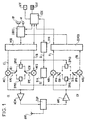
- This dual mode terminal illustrated in a simplified way by the figure, includes in particular a CLV keyboard and a display AFF, associated with a CDE control device, which allow the terminal user to control the terminal to access one of two radio systems at least, for example to the well-known GSM and DECT systems, and which allow it to exchange signals with these systems, for obtaining radio communications.
- These communications can take various forms. We have shown only an HP speaker and an M microphone for voice communications associated with a CODEC speech coder / decoder which is itself coupled to a MOD modulator and a DEMOD demodulator.
- the CE emission chain of this terminal also includes the MOD modulator, having two EI and EQ outputs on which are supplied baseband signals to transmit, two broadcast mixers MEI and MEQ whose outputs are jointly coupled to an amplifier AEM emission, the output of the latter, reaching, by a DUP duplexer ANT antenna.
- the reception chain CR of this terminal includes, at from the ANT antenna and the DUP duplexer, a ARC reception amplifier, two reception mixers MRI and MRQ providing RI and RQ inputs to the DEMOD demodulator for band reception signals based.
- the voice signals from the microphone M, coded in digital form in the CODEC coder / decoder are set in transmission format in the MOD modulator which produces signals to be transmitted in the form of transmission symbols successive each comprising two unit transmission signals respectively provided on the EI and EQ outputs.
- the unit emission signal EI affects the amplitude of a local phase emission wave 0 °.
- the signal unit EQ emission affects the amplitude of a local wave emission in phase quadrature with the previous one.
- the addition of these two local emission waves as well modulated, at the input of the emission amplifier AEM provides the radio signal to be transmitted or the transmission signal.
- a radio signal to receive, or signal reception, after amplification in the ARC amplifier identically attacks the reception mixers MRI and MRQ.
- the signal reception combines with a local phase reception wave 0 ° and this provides a unitary signal reception on the input RI of the DEMOD demodulator.
- the reception signal combines with a local wave reception in quadrature phase with the previous and this provides a unit reception signal on the RQ input of the DEMOD demodulator.
- the DEMOD demodulator recognize the symbols formed by these unit signals, demodulates them and provides coded speech signals to the CODEC encoder / decoder, which produces sounds through the speaker HP.
- the CDE control device is coupled, in particular, to the CODEC coder / decoder to take knowledge of the signals received and to control their operation.
- the terminal under the control of the user, by the means the AFF display and the CLV keyboard, acting on the CDE control device, or generated internal states periodically and automatically in the CDE command is at certain times in the state transmission to the DECT radio system.
- IEC, CEQ, CRI, CRQ switches, controlled by the CDE control device by links not shown, are in the positions shown in the Fig.
- the CDE control device is in relationship with a tunable source SYN, a synthesizer digital frequency, for example, and commands it to produce a local emission wave from the DECT system.
- This local wave is provided on the OL output of the SYN synthesizer and supplies a DECT transmission phase shifter DPH1, which provides to the first MEI emission mixer, by a first IEC emission switch in the position shown, a local wave DECT transmission of phase 0 ° and, on the second emission mixer MEQ, by a second emission switch CEQ in the position shown, a local emission wave DECT in phase quadrature.
- DECT transmission phase shifter DPH1 which provides to the first MEI emission mixer, by a first IEC emission switch in the position shown, a local wave DECT transmission of phase 0 ° and, on the second emission mixer MEQ, by a second emission switch CEQ in the position shown, a local emission wave DECT in phase quadrature.
- Signals to transmit thus modulate a local wave DECT emission supplied directly from the SYN tunable source.
- Some orders different from the CDE control device similarly allow to modulate other local waves DECT emission corresponding to other channels in the frequency band allocated to the DECT system. This
- the terminal does not receive. More generally, as long as the terminal does not receive not, the reception chain is blocked. It was illustrated, by way of example of a locking means, by the fact that CRI and CRQ receive switches are in the represented position, designated by RPR, in which the two receiving mixers MRI and MRQ receive no local wave.
- the terminal does not transmit.
- the broadcast chain is then blocked. This was illustrated, likewise, by the fact that the IEC and CEQ transmit switches are in a additional position, designated by RPE, in which the two emission mixers MEI and MEQ receive no waves local.
- the reception switches CRI and CRD are set by the CDE control device in such a position that they couple the MRI and MRQ receiving mixers to a DECT reception phase shifter DPH3, which receives a local wave DECT reception generated in the SYN synthesizer under the control of the CDE control device and product, to the first MRI receiving mixer, via the first switch CRI reception, a local DECT reception phase shifted by 0 ° and, towards the second MRQ receiving mixer, by the second CRQ receive switch, a local wave DECT reception in phase quadrature.
- the mixers reception MRI and MRQ can thus produce the signals RI and RQ baseband reception units towards the DEMOD demodulator.
- the latter coupled by a link of control with the CDE control device, provides coded signals to the CODEC coder / decoder which transforms them into voice signals from the loudspeaker.
- the same dual mode terminal shown in the figure is also intended for communications by another system radio communications such as the GSM system.
- radio communications such as the GSM system.
- the coding and formatting are suitable for this different system in MOD modulator, DEMOD demodulator, CODEC coder / decoder, different local waves must be provided for transmit and receive radio signals from this other system.
- the illustrated terminal comprises, downstream of said tunable source SYN, a frequency changer switchable DIV so that the source can respond directly to the needs of a radiocommunication system, as we have just seen, the insertion of said changer frequency, makes it capable of meeting the needs of a other radiocommunication system, thanks to a change determined from the frequency produced by said source SYN tunable provided by said DIV frequency changer.
- this frequency changer brings a division of the frequency provided by the SYN synthesizer by a determined factor, here equal to 2. It it is therefore a simple frequency division stage, such a flip-flop D, which is connected to the output dy SYN synthesizer and whose OL 'output provides the local wave GSM required.
- the GSM system uses the bands of frequencies 890 - 915 MHz and 935 - 960 MHz, i.e. overall 890 - 960 MHz.
- the invention provides for producing, using the source unique tunable which is the SYN synthesizer, frequencies in the band 1780 - 1920 MHz, to divide them by 2 using the DIV divider and thus obtain the frequencies required in the frequency band 890 - 960 MHz. More generally the invention plans to produce in the SYN synthesizer of frequencies in a matching band substantially to that directly provided by this synthesizer and change these frequencies by an operation such as the division, multiplication, addition or subtraction (there are simple circuits accomplishing these four operations) to obtain the frequencies of another band of frequency, or several other frequency bands, in a multimode terminal. Switching means, here CEI, CEQ, CRI, CRQ, allow you to choose between the different frequency bands.
- the terminal is put into GSM transmission by the CDE control device which places the two emission switch CEI and CEQ in a position such that the output OL 'of the divider DIV connected to a GSM DPH2 transmission phase shifter provides a local wave GSM transmission of phase 0 ° to the first mixer mixing MEI, and a local GSM transmission wave in quadrature phase at second emission mixer MEQ.
- the broadcast thus takes place, as described above, but in the GSM system. he it suffices that the SYN synthesizer, under the control of the CDE control device provides on its output Ol a twice the frequency of the GSM channel desired.
- a reception phase shifter GSM DPH4 receiving a local wave OL 'from the divider DIV, connected to the MRI and MRQ reception mixers by CRI and CRQ switches, allows reception of GSM signals.
Landscapes
- Engineering & Computer Science (AREA)
- Computer Networks & Wireless Communication (AREA)
- Signal Processing (AREA)
- Power Engineering (AREA)
- Transceivers (AREA)
- Input Circuits Of Receivers And Coupling Of Receivers And Audio Equipment (AREA)
- Switch Cases, Indication, And Locking (AREA)
- Connector Housings Or Holding Contact Members (AREA)
- Coupling Device And Connection With Printed Circuit (AREA)
- Circuits Of Receivers In General (AREA)
- Superheterodyne Receivers (AREA)
Abstract
Description
La présente invention concerne les radiocommunications numériques et, plus particulièrement, un terminal de radiocommunication susceptible de fonctionner alternativement dans au moins deux systèmes de radiocommunication distincts exploitant des bandes de fréquences relativement proches, c'est-à-dire pouvant être traitées par des mêmes moyens technologiques.The present invention relates to digital radio communications and, more particularly, a radiocommunication terminal likely to work alternately in at least two separate radio systems using bands relatively close frequencies, that is to say which can be processed by the same technological means.
L'invention s'appliquera notamment dans un termina bimode GSM/DECT. On rappelle que le système GSM exploite respectivement les bandes de fréquences 890-916 MHz et 935 960 MHz, pour les deux sens de transmission, tandis que le système DECT exploite la bande de fréquence 1880-1900 MHz.The invention will apply in particular in a dual mode GSM / DECT. It is recalled that the GSM system exploits the bands respectively frequencies 890-916 MHz and 935 960 MHz, for both directions of transmission, while the DECT system operates the frequency 1880-1900 MHz.
Dans un terminal de radiocommunication, un oscillateur local produit, à l'émission, une onde à la fréquence d'un canal émission et, à la réception, une onde à la fréquence d'un canal réception. L'onde à la fréquence de canal émission, ou onde locale émission, est modulée par le signal à transmettre pour fournir un signal émission. L'onde à la fréquence de canal réception, ou onde locale réception, sert à démoduler un signal de réception portant l'information à recevoir. Dans le cas de la démodulatio directe, l'onde locale réception est combinée vectoriellement avec le signal réception reçu à l'antenne et fournit un signal d'information en bande de base.In a radiocommunication terminal, a local oscillator produces, on transmission, a wave at the frequency of a transmission channel and, at reception, a wave at the frequency of a reception channel. The wave at the transmit channel frequency, or local transmit wave, is modulated by the signal to be transmitted to provide a signal program. The wave at the reception channel frequency, or local wave reception, used to demodulate a reception signal carrying information to be received. In the case of direct demodulation, the local reception wave is combined vectorially with the signal reception received on the antenna and provides an information signal in base band.
Un terminal, lors de communications différentes doit être accordé sur des canaux émission et réception qui sont chaque fois l'un et l'autre différents, selon les disponibilités locales dun système dans lequel il estexploité. Les ondes locales émission et réception sont donc fournies par au moins une source accordable sur les canaux de ce système. Comme, dans les systèmes de radiocommunication numériques considérés actuellement, la transmission a lieu dans une trame temporelle et est aménagée pour que l'émission et la réception soient séparées dans le temps, une source accordable unique est suffisante.A terminal, for different communications must be granted on transmission and reception channels which are each one and the other different, depending on the local availability of a system in which it is operated. Local radio transmitting and receiving are therefore provided by at least one tunable source on the channels of this system. Like, in radiocommunication systems currently considered digital, transmission takes place in a time frame and is arranged so that transmission and reception are separated in time, a single tunable source is sufficient.
Dans le cas d'un terminal bimode, les solutions classiques demanderaient soit une source accordable unique, mais à largeur de bande considérablement accrue, soit deux sources accordables distinctes, une par système de radiocommunication.In the case of a dual-mode terminal, the conventional solutions would require either a single tunable source, but width significantly increased band, two tunable sources separate, one per radio system.
Le document GB-A-2258776 décrit un terminal de radiocommunication bi-bande et bi-système. Le document WO 89/ 07865 décrit un terminal radio multibande incluant un émetteur- récepteur dont la voie de transmission est à large bande de manière à couvrir deux bandes de fréquences.GB-A-2258776 describes a radiocommunication terminal dual-band and dual-system. The document WO 89/07865 describes a terminal multiband radio including a transceiver whose channel transmission is broadband so as to cover two bands of frequencies.
On a déjà envisagé, comme décrit dans le document de brevet FR-A-93 07 775, de n'employer qu'une seule source accordable de largeur de bande limitée. Le principe adopté est de mettre d'abord en concordance les bandes de fréquences des deux systèmes, puis d'accorder le terminal sur un canal émission ou réception à l'aide d'une source accordable unique dont la bande de fréquences d'accord est à peu près celle de l'un des systèmes seulement.We have already envisaged, as described in patent document FR-A-93 07 775, to use only one tunable source with a width of limited band. The principle adopted is to first put in match the frequency bands of the two systems and then tune the terminal on a transmit or receive channel using from a single tunable source whose tuning frequency band is roughly that of one of the systems only.
Toutefois, cela demande, en réception, l'adjonction d'une chaíne de démodulation intermédiaire ramenant la bande de réception de l'un des systèmes en concordance avec la bande de réception de l'autre système.However, this requires, in reception, the addition of a chain of intermediate demodulation bringing back the reception band of one systems in accordance with the reception band of the other system.
La présente invention a donc pour objet un terminal de radiocommunication selon la revendication 1 comportant, comme le précédent, une source accordable d'ondes locales émission et/ou réception constituée par un synthétiseur de fréquences, pour permettre au terminal d'émettre et/ou de recevoir des canaux dans des bandes de fréquences différentes relatives à au moins deux systèmes de radiocommunication, des mélangeurs d'émission et de réception respectivement reliés les uns à un modulateur et les autres à un démodulateur de signaux en bande de base.The present invention therefore relates to a terminal for radiocommunication according to claim 1 comprising, like the preceding one, a source tunable of local waves emission and / or reception constituted by a frequency synthesizer, to allow the terminal to transmit and / or receive channels in frequency bands different relating to at least two systems of radio communication, transmit and receive mixers respectively connected one to a modulator and the other to a baseband signal demodulator.
Selon une caractéristique de l'invention, ce terminal comporte, en aval de ladite source accordable, constituée par un synthétiseur de fréquences apte à fournir les fréquences d'une bande exploitée par un système, un changeur de fréquence commutable à changement de fréquence fixe, inséré ou non permettant de changer de fréquences, relié à un synthétiseur pour recevoir les fréquences que celui-ci fournit et pour les changer en fréquences d'une autre bande exploitée par un autre système, ceci par une opération, telle qu'une division, une multiplication, une addition ou une soustraction, ainsi que des commutateurs respectivement reliés chacun à un des mélangeurs pour lui transmettre une onde locale provenant soit du synthétiseur, soit du changeur, sous l'action d'un dispositif de commande permettant à un usager de commander le terminal pour accéder aux systèmes.According to a characteristic of the invention, this terminal comprises, in downstream of said tunable source, constituted by a synthesizer of frequencies capable of supplying the frequencies of a band operated by a system, a switchable frequency changer with fixed frequency change, inserted or not allowing to change frequencies, connected to a synthesizer to receive the frequencies which this one provides and to change them to frequencies of another band operated by a other system, this by an operation, such as a division, a multiplication, addition or subtraction, as well as switches respectively connected each to one of the mixers for transmit a local wave from either the synthesizer or of the changer, under the action of a control device allowing a user to control the terminal to access the systems.
Dans une forme de réalisation, le changeur est agencé pour permettre d'apporter une division par un facteur déterminé de la fréquence de la source accordable. Ledit facteur est 2, en particulier dans le cas d'un terminal bimode GSM/DECT.In one embodiment, the changer is arranged to allow to bring a division by a determined factor of the frequency of the tunable source. Said factor is 2, in particular in the case of a dual-mode GSM / DECT terminal.
Avantageusement, les sorties de la source accordable et du changeur de fréquence sont suivies chacune d'un déphaseur fournissant deux ondes déphasées de 90° pour la modulation/démodulation de signaux de deux systèmes de radiocommunication appliquant une modulation en quadrature.Advantageously, the outputs of the tunable source and the frequency changer are each followed by phase shifter providing two 90 ° phase shifted waves for the modulation / demodulation of signals from two signal systems radiocommunication applying quadrature modulation.
Avantageusement encore, deux mélangeurs seulement sont prévus pour la modulation/démodulation des signaux de deux systèmes de radiocommunication, ces mélangeurs recevant les ondes déphasées de 90° de l'un ou de l'autre de deux desdits déphaseurs.Advantageously still, only two mixers are provided for modulation / demodulation of signals from two radiocommunication systems, these mixers receiving the waves 90 ° out of phase from either of two of the said shifters.
Les différents objets et caractéristiques de l'invention seront détaillés dans la description qui va suivre d'un exemple de mise en oeuvre de l'invention, fourni à titre d'exemple non limitatif, en se référant à la figure annexée qui représente un terminal bimode agencé conformément à l'invention.The different objects and characteristics of the invention will be detailed in the description which will follow an example of implementation of the invention, provided by way of nonlimiting example, with reference to the figure annexed which represents a dual mode terminal arranged according to the invention.
Ce terminal bimode, illustré de façon simplifiée par la figure, comprend notamment un clavier CLV et un afficheur AFF, associés à un dispositif de commande CDE, qui permettent à l'usager du terminal de commander le terminal pour accéder à l'un de deux systèmes de radiocommunications au moins, par exemple aux systèmes bien connus GSM et DECT, et qui lui permettent d'échanger des signaux avec ces systèmes, pour obtenir des communications par voie radio. Ces communications peuvent prendre des formes diverses. On a représenté seulement un haut-parleur HP et un microphone M pour les communications vocales associés à un codeur/décodeur de parole CODEC qui est lui-même couplé à un modulateur MOD et à un démodulateur DEMOD.This dual mode terminal, illustrated in a simplified way by the figure, includes in particular a CLV keyboard and a display AFF, associated with a CDE control device, which allow the terminal user to control the terminal to access one of two radio systems at least, for example to the well-known GSM and DECT systems, and which allow it to exchange signals with these systems, for obtaining radio communications. These communications can take various forms. We have shown only an HP speaker and an M microphone for voice communications associated with a CODEC speech coder / decoder which is itself coupled to a MOD modulator and a DEMOD demodulator.
La chaíne émission CE de ce terminal comprend, outre le modulateur MOD, ayant deux sorties EI et EQ sur lesquelles sont fournis des signaux en bande de base à transmettre, deux mélangeurs émission MEI et MEQ dont les sorties sont conjointement couplées à un amplificateur d'émission AEM, la sortie de ce dernier, atteignant, par un duplexeur DUP une antenne ANT.The CE emission chain of this terminal also includes the MOD modulator, having two EI and EQ outputs on which are supplied baseband signals to transmit, two broadcast mixers MEI and MEQ whose outputs are jointly coupled to an amplifier AEM emission, the output of the latter, reaching, by a DUP duplexer ANT antenna.
La chaíne de réception CR de ce terminal comprend, à partir de l'antenne ANT et du duplexeur DUP, un amplificateur de réception ARC, deux mélangeurs réception MRI et MRQ fournissant à des entrées RI et RQ du démodulateur DEMOD des signaux de réception en bande de base.The reception chain CR of this terminal includes, at from the ANT antenna and the DUP duplexer, a ARC reception amplifier, two reception mixers MRI and MRQ providing RI and RQ inputs to the DEMOD demodulator for band reception signals based.
A l'émission, les signaux vocaux du micro M, codés sous forme numérique dans le codeur/décodeur CODEC sont mis au format de transmission dans le modulateur MOD qui produit les signaux à transmettre sous forme de symboles émission successifs comprenant chacun deux signaux unitaires émission respectivement fournis sur les sorties EI et EQ. Dans un premier mélangeur émission MEI, le signal unitaire émission EI affecte l'amplitude d'une onde locale émission de phase 0°. Dans un deuxième mélangeur émission MEQ, le signal unitaire émission EQ affecte l'amplitude d'une onde locale émission en quadrature de phase avec la précédente. L'addition de ces deux ondes locales émission ainsi modulées, à l'entrée de l'amplificateur émission AEM fournit le signal radio à transmettre ou signal émission.On transmission, the voice signals from the microphone M, coded in digital form in the CODEC coder / decoder are set in transmission format in the MOD modulator which produces signals to be transmitted in the form of transmission symbols successive each comprising two unit transmission signals respectively provided on the EI and EQ outputs. In one first MEI emission mixer, the unit emission signal EI affects the amplitude of a local phase emission wave 0 °. In a second emission mixer MEQ, the signal unit EQ emission affects the amplitude of a local wave emission in phase quadrature with the previous one. The addition of these two local emission waves as well modulated, at the input of the emission amplifier AEM provides the radio signal to be transmitted or the transmission signal.
A la réception, un signal radio à recevoir, ou signal de réception, après amplification dans l'amplificateur ARC, attaque identiquement les mélangeurs réception MRI et MRQ. Dans un premier mélangeur réception MRI, le signal de réception se combine avec une onde locale réception de phase 0° et cela fournit un signal unitaire réception sur l'entrée RI du démodulateur DEMOD. Dans un deuxième mélangeur réception MRQ, le signal de réception se combine avec une onde locale réception en quadrature de phase avec la précédente et cela fournit un signal unitaire réception sur l'entrée RQ du démodulateur DEMOD. Le démodulateur DEMOD reconnaít les symboles que forment ces signaux unitaires, les démodule et fournit des signaux de parole codés au codeur/décodeur CODEC, lequel produit des sons au travers du haut-parleur HP. Le dispositif de commande CDE est couplé, notamment, au codeur/décodeur CODEC pour prendre connaissance des signaux reçus et pour en commander le fonctionnement.On reception, a radio signal to receive, or signal reception, after amplification in the ARC amplifier, identically attacks the reception mixers MRI and MRQ. In a first MRI receiving mixer, the signal reception combines with a local phase reception wave 0 ° and this provides a unitary signal reception on the input RI of the DEMOD demodulator. In a second mixer MRQ reception, the reception signal combines with a local wave reception in quadrature phase with the previous and this provides a unit reception signal on the RQ input of the DEMOD demodulator. The DEMOD demodulator recognize the symbols formed by these unit signals, demodulates them and provides coded speech signals to the CODEC encoder / decoder, which produces sounds through the speaker HP. The CDE control device is coupled, in particular, to the CODEC coder / decoder to take knowledge of the signals received and to control their operation.
Bien entendu, ce qui précède est très schématique mais correspond à une technique bien connue et suffira à la compréhension de la présente invention.Of course, the above is very schematic but corresponds to a well-known technique and will suffice for the understanding of the present invention.
Le terminal sous la commande de l'usager, par le moyen de l'afficheur AFF et du clavier CLV, agissant sur le dispositif de commande CDE, ou d'états internes engendrés périodiquement et automatiquement dans le dispositif de commande CDE se trouve à certains moments dans l'état d'émission vers le système de radiocommunication DECT. A ce moment, des commutateurs CEI, CEQ, CRI, CRQ, commandés par le dispositif de commande CDE par des liaisons non représentées, sont dans les positions représentées à la figure. Par ailleurs, le dispositif de commande CDE est en relation avec une source accordable SYN, un synthétiseur de fréquence numérique, par exemple, et lui commande de produire une onde locale émission du système DECT. Cette onde locale est fournie sur la sortie OL du synthétiseur SYN et alimente un déphaseur émission DECT DPH1, lequel fournit au premier mélangeur émission MEI, par un premier commutateur émission CEI dans la position représentée, une onde locale émission DECT de phase 0° et, au deuxième mélangeur émission MEQ, par un deuxième commutateur émission CEQ dans la position représentée, une onde locale émission DECT en quadrature de phase. Les signaux à transmettre modulent ainsi une onde locale émission DECT fournie directement par la source accordable SYN. Des commandes différentes du dispositif de commande CDE permettent de même de moduler d'autres ondes locales émission DECT correspondant à d'autres canaux de la bande de fréquence allouée au système DECT. Cette bande de fréquence s'étend de 1880 à 1900 MHz. The terminal under the control of the user, by the means the AFF display and the CLV keyboard, acting on the CDE control device, or generated internal states periodically and automatically in the CDE command is at certain times in the state transmission to the DECT radio system. At this moment, IEC, CEQ, CRI, CRQ switches, controlled by the CDE control device by links not shown, are in the positions shown in the Fig. In addition, the CDE control device is in relationship with a tunable source SYN, a synthesizer digital frequency, for example, and commands it to produce a local emission wave from the DECT system. This local wave is provided on the OL output of the SYN synthesizer and supplies a DECT transmission phase shifter DPH1, which provides to the first MEI emission mixer, by a first IEC emission switch in the position shown, a local wave DECT transmission of phase 0 ° and, on the second emission mixer MEQ, by a second emission switch CEQ in the position shown, a local emission wave DECT in phase quadrature. Signals to transmit thus modulate a local wave DECT emission supplied directly from the SYN tunable source. Some orders different from the CDE control device similarly allow to modulate other local waves DECT emission corresponding to other channels in the frequency band allocated to the DECT system. This frequency band extends from 1880 to 1900 MHz.
Parallèlement, une liaison bilatérale prévue entre le dispositif de commande CDE et le modulateur MOD, tout comme la liaison bilatérale prévue entre le dispositif de commande CDE et le codeur/décodeur CODEC, font que le codage et le formattage des signaux à transmettre respectent les règles du système DECT.At the same time, a bilateral link planned between the CDE controller and MOD modulator just like the bilateral connection planned between the control device CDE and the CODEC coder / decoder, make the coding and formatting the signals to be transmitted respect the rules of the DECT system.
Par ailleurs, à l'instant que l'on vient de considérer, réservé à l'émission, le terminal ne reçoit pas. D'une façon plus générale, tant que le terminal ne reçoit pas, la chaíne de réception est bloquée. Cela a été illustré, à titre d'exemple de moyen de blocage, par le fait que des commutateurs réception CRI et CRQ sont dans la position représentée, désignée par RPR, dans laquelle les deux mélangeurs réception MRI et MRQ ne reçoivent aucune onde locale.Furthermore, just as we just consider, reserved for transmission, the terminal does not receive. More generally, as long as the terminal does not receive not, the reception chain is blocked. It was illustrated, by way of example of a locking means, by the fact that CRI and CRQ receive switches are in the represented position, designated by RPR, in which the two receiving mixers MRI and MRQ receive no local wave.
A d'autres moments, notamment ceux qui sont réservés à la réception, le terminal n'émet pas. La chaíne d'émission est alors bloquée. Cela a été illustré, de même, par le fait que les commutateurs émission CEI et CEQ sont dans une position additionnelle, désignée par RPE, dans laquelle les deux mélangeurs émission MEI et MEQ ne reçoivent aucune onde locale.At other times, especially those reserved for reception, the terminal does not transmit. The broadcast chain is then blocked. This was illustrated, likewise, by the fact that the IEC and CEQ transmit switches are in a additional position, designated by RPE, in which the two emission mixers MEI and MEQ receive no waves local.
Lorsque le terminal doit recevoir, dans le système DECT toujours, les commutateur réception CRI et CRD sont mis par le dispositif de commande CDE dans une position telle qu'ils couplent les mélangeurs réception MRI et MRQ à un déphaseur réception DECT DPH3, lequel reçoit une onde locale réception DECT engendrée dans le synthétiseur SYN sous la commande du dispositif de commande CDE et produit, vers le premier mélangeur réception MRI, par le premier commutateur réception CRI, une onde locale réception DECT déphasée de 0° et, vers le deuxième mélangeur réception MRQ, par le deuxième commutateur réception CRQ, une onde locale réception DECT en quadrature de phase. Les mélangeurs réception MRI et MRQ peuvent ainsi produire les signaux unitaires réception en bande de base RI et RQ vers le démodulateur DEMOD. Ce dernier, couplé par une liaison de commande avec le dispositif de commande CDE, fournit des signaux codés au codeur/décodeur CODEC qui les transforme en signaux vocaux émis par le haut-parleur HP.When the terminal must receive, in the system DECT always, the reception switches CRI and CRD are set by the CDE control device in such a position that they couple the MRI and MRQ receiving mixers to a DECT reception phase shifter DPH3, which receives a local wave DECT reception generated in the SYN synthesizer under the control of the CDE control device and product, to the first MRI receiving mixer, via the first switch CRI reception, a local DECT reception phase shifted by 0 ° and, towards the second MRQ receiving mixer, by the second CRQ receive switch, a local wave DECT reception in phase quadrature. The mixers reception MRI and MRQ can thus produce the signals RI and RQ baseband reception units towards the DEMOD demodulator. The latter, coupled by a link of control with the CDE control device, provides coded signals to the CODEC coder / decoder which transforms them into voice signals from the loudspeaker.
Le même terminal bimode représenté par la figure est également prévu pour des communications par un autre système de radiocommunication tel que le système GSM. En dehors du fait que les dispositions relatives au codage et au formattage sont adaptées à ce système différent dans les modulateur MOD, démodulateur DEMOD, codeur/décodeur CODEC, des ondes locales différentes doivent être fournies pour transmettre et recevoir les signaux radio de cet autre système.The same dual mode terminal shown in the figure is also intended for communications by another system radio communications such as the GSM system. Outside of that the coding and formatting are suitable for this different system in MOD modulator, DEMOD demodulator, CODEC coder / decoder, different local waves must be provided for transmit and receive radio signals from this other system.
A cette fin, le terminal illustré comprend, en aval de ladite source accordable SYN, un changeur de fréquence commutable DIV de sorte que, la source pouvant répondre directement aux besoins d'un système de radiocommunication, comme on vient de le voir, l'insertion dudit changeur de fréquence, la rende capable de répondre aux besoins d'un autre système de radiocommunication, grâce à un changement déterminé de la fréquence produite par ladite source accordable SYN apporté par ledit changeur de fréquence DIV.To this end, the illustrated terminal comprises, downstream of said tunable source SYN, a frequency changer switchable DIV so that the source can respond directly to the needs of a radiocommunication system, as we have just seen, the insertion of said changer frequency, makes it capable of meeting the needs of a other radiocommunication system, thanks to a change determined from the frequency produced by said source SYN tunable provided by said DIV frequency changer.
Dans l'exemple décrit, ce changeur de fréquence apporte une division de la fréquence fournie par le synthétiseur SYN par un facteur déterminé, ici égal à 2. Il s'agit donc d'un simple étage de division de fréquence, tel qu'une bascule D, qui est connecté à la sortie dy synthétiseur SYN et dont la sortie OL' fournit l'onde locale GSM requise.In the example described, this frequency changer brings a division of the frequency provided by the SYN synthesizer by a determined factor, here equal to 2. It it is therefore a simple frequency division stage, such a flip-flop D, which is connected to the output dy SYN synthesizer and whose OL 'output provides the local wave GSM required.
On rappelle que le système GSM emploie les bandes de fréquences 890 - 915 MHz et 935 - 960 MHz, c'est-à-dire globalement 890 - 960 MHz.It is recalled that the GSM system uses the bands of frequencies 890 - 915 MHz and 935 - 960 MHz, i.e. overall 890 - 960 MHz.
L'invention prévoit de produire, à l'aide de la source accordable unique qui est le synthétiseur SYN, des fréquences de la bande 1780 - 1920 MHz, pour les diviser par 2 à l'aide du diviseur DIV et ainsi obtenir les fréquences nécessaires de la bande de fréquences 890 - 960 MHz. Plus généralement, l'invention prévoit de produire dans le synthétiseur SYN des fréquences d'une bande concordant sensiblement à celle que fournit directement ce synthétiseur et de changer ces fréquences par une opération telle que la division, la multiplication, l'addition ou la soustraction (il existe des circuits simples accomplissant ces quatre opérations) pour obtenir les fréquences d'une autre bande de fréquence, ou de plusieurs autres bandes de fréquences, dans un terminal multimode. Des moyens de commutation, ici CEI, CEQ, CRI, CRQ, permettent de choisir entre les différentes bandes de fréquences.The invention provides for producing, using the source unique tunable which is the SYN synthesizer, frequencies in the band 1780 - 1920 MHz, to divide them by 2 using the DIV divider and thus obtain the frequencies required in the frequency band 890 - 960 MHz. More generally the invention plans to produce in the SYN synthesizer of frequencies in a matching band substantially to that directly provided by this synthesizer and change these frequencies by an operation such as the division, multiplication, addition or subtraction (there are simple circuits accomplishing these four operations) to obtain the frequencies of another band of frequency, or several other frequency bands, in a multimode terminal. Switching means, here CEI, CEQ, CRI, CRQ, allow you to choose between the different frequency bands.
Plus précisément, dans l'exemple décrit, le terminal est mis en émission GSM par le dispositif de commande CDE qui place les deux commutateur émission CEI et CEQ dans une position telle que la sortie OL' du diviseur DIV connectée à un déphaseur émission GSM DPH2 fournit une onde locale émission GSM de phase 0° au premier mélangeur émission MEI, et une onde locale émission GSM en quadrature de phase au deuxième mélangeur émission MEQ. L'émission a ainsi lieu, comme décrit précédemment, mais dans le système GSM. Il suffit que le synthétiseur SYN, sous la commande du dispositif de commande CDE fournisse sur sa sortie Ol une fréquence double de celle qui doit porter le canal GSM voulu.More specifically, in the example described, the terminal is put into GSM transmission by the CDE control device which places the two emission switch CEI and CEQ in a position such that the output OL 'of the divider DIV connected to a GSM DPH2 transmission phase shifter provides a local wave GSM transmission of phase 0 ° to the first mixer mixing MEI, and a local GSM transmission wave in quadrature phase at second emission mixer MEQ. The broadcast thus takes place, as described above, but in the GSM system. he it suffices that the SYN synthesizer, under the control of the CDE control device provides on its output Ol a twice the frequency of the GSM channel desired.
De façon tout-à-fait similaire, un déphaseur réception GSM DPH4 recevant une onde locale OL' issue du diviseur DIV, connecté aux mélangeurs réceptions MRI et MRQ par les commutateurs CRI et CRQ, permet la réception de signaux GSM.In a very similar way, a reception phase shifter GSM DPH4 receiving a local wave OL 'from the divider DIV, connected to the MRI and MRQ reception mixers by CRI and CRQ switches, allows reception of GSM signals.
Claims (5)
- A radio communication terminal including a single tunable source of send and/or receive local waves consisting of a frequency synthesizer, to enable the terminal to send and/or receive channels in different frequency bands relative to at least two radio communication systems, send and receive mixers (MRI, MRQ) respectively connected the ones to a modulator (MOD) and the others to a demodulator (DEMOD) of baseband signals, characterized in that said terminal includes, downstream of said tunable source consisting of a frequency synthesizer (SYN) able to supply directly the frequencies of a band used by a first system, a frequency changer (DIV), connected to said synthesizer to receive the frequencies that it supplies and to change them into frequencies of another band used by another system, by an operation such as a division, a multiplication, an addition or a subtraction, and switches (CEI, CEQ, CRI, CRQ) respectively each connected to one of the mixers to send it a local wave coming either from the synthesizer (SYN) or from the changer (DIV), under the action of a control device (CDE) enabling a user to control the terminal to access one or the other of the radio communication systems alternately.
- A radio communication terminal claimed in claim 1 characterized in that said frequency changer (DIV) divides the frequencies by a particular factor.
- A radio communication terminal claimed in claim 2 characterized in that said factor is 2.
- A radio communication terminal according to claim 1, 2, or 3, characterized in that the outputs of the synthesizer (SYN) and the changer (DIV) are each followed by a phase-shifter (DPH1 to DPH4) supplying two waves phase-shifted by 90° for modulating/demodulating radio communication system signals applying quadrature modulation.
- A radio communication terminal claimed in claim 4 characterized in that only two mixers are provided for modulating/demodulating receive signals of said two radio communication systems, said mixers receiving signals phase-shifted 90° from one or the other of the two said phase-shifters.
Applications Claiming Priority (2)
| Application Number | Priority Date | Filing Date | Title |
|---|---|---|---|
| FR9515396A FR2742946B1 (en) | 1995-12-22 | 1995-12-22 | MULTIMODE RADIOCOMMUNICATION TERMINAL |
| FR9515396 | 1995-12-22 |
Publications (2)
| Publication Number | Publication Date |
|---|---|
| EP0780968A1 EP0780968A1 (en) | 1997-06-25 |
| EP0780968B1 true EP0780968B1 (en) | 2002-09-04 |
Family
ID=9485883
Family Applications (1)
| Application Number | Title | Priority Date | Filing Date |
|---|---|---|---|
| EP96402703A Expired - Lifetime EP0780968B1 (en) | 1995-12-22 | 1996-12-12 | Multimode radio communications terminal |
Country Status (5)
| Country | Link |
|---|---|
| US (1) | US5953641A (en) |
| EP (1) | EP0780968B1 (en) |
| AT (1) | ATE223629T1 (en) |
| DE (1) | DE69623426T2 (en) |
| FR (1) | FR2742946B1 (en) |
Families Citing this family (29)
| Publication number | Priority date | Publication date | Assignee | Title |
|---|---|---|---|---|
| JPH1141131A (en) * | 1997-07-15 | 1999-02-12 | Toshiba Corp | Radio communication device |
| JP3825540B2 (en) * | 1997-09-05 | 2006-09-27 | 松下電器産業株式会社 | Receiver and transceiver |
| JP3848445B2 (en) * | 1997-09-26 | 2006-11-22 | 松下電器産業株式会社 | Radio equipment compatible with multiple communication systems |
| US6510310B1 (en) * | 1998-01-26 | 2003-01-21 | Conexant Systems, Inc. | Dual mode phone architecture utilizing a single transmit-receive switch |
| US6993314B2 (en) * | 1998-05-29 | 2006-01-31 | Silicon Laboratories Inc. | Apparatus for generating multiple radio frequencies in communication circuitry and associated methods |
| US20030003887A1 (en) * | 1998-05-29 | 2003-01-02 | Lysander Lim | Radio-frequency communication apparatus and associated methods |
| FI112741B (en) | 1998-11-26 | 2003-12-31 | Nokia Corp | Method and arrangement for transmitting and receiving RF signals at various radio interfaces of communication systems |
| JP3326133B2 (en) * | 1999-04-02 | 2002-09-17 | 松下電器産業株式会社 | Wireless device and method |
| DE19916574C1 (en) * | 1999-04-13 | 2001-01-18 | Siemens Ag | Frequency processing system for a mobile radio dual band transmitter / receiver (transceiver) |
| NO329890B1 (en) * | 1999-11-15 | 2011-01-17 | Hitachi Ltd | The mobile communication apparatus |
| DE19956073C2 (en) * | 1999-11-22 | 2002-03-28 | Infineon Technologies Ag | modulation arrangement |
| US6717981B1 (en) * | 1999-12-14 | 2004-04-06 | Koninklijke Philips Electronics N.V. | Transmitter image suppression in TDD transceivers |
| JP2001177433A (en) * | 1999-12-21 | 2001-06-29 | Murata Mfg Co Ltd | High frequency composite component and mobile communication device |
| DE69921495T2 (en) * | 1999-12-23 | 2005-02-24 | Freescale Semiconductor, Inc., Austin | Dual mode with a single receiver circuit |
| US20020137469A1 (en) * | 2000-07-24 | 2002-09-26 | Manabu Yamaguchi | Radio communication apparatus and radio communication method |
| US6665284B1 (en) * | 2000-07-31 | 2003-12-16 | Nokia Mobile Phones, Ltd. | Apparatus, and associated method, for receiving data at a radio device |
| US20020127992A1 (en) * | 2001-03-08 | 2002-09-12 | Fransis Bert L. | Wideband local oscillator architecture |
| US20020127985A1 (en) * | 2001-03-08 | 2002-09-12 | Fransis Bert L. | Wideband local oscillator architecture |
| DE10114779A1 (en) * | 2001-03-26 | 2002-10-24 | Infineon Technologies Ag | Sending and receiving unit |
| US6487398B1 (en) | 2001-08-14 | 2002-11-26 | Motorola, Inc. | Low noise architecture for a direct conversion transmitter |
| US20030092419A1 (en) * | 2001-11-09 | 2003-05-15 | Dan Nobbe | Method and apparatus for a near-unity divider in a direct conversion communication device |
| DE10317598A1 (en) * | 2003-04-16 | 2004-11-25 | Infineon Technologies Ag | Integrated transceiver circuit |
| DE10345972B4 (en) * | 2003-10-02 | 2006-04-20 | Siemens Ag | Device with adaptive radio transmission and / or radio reception architecture and method for its operation |
| CN1625065A (en) * | 2003-12-05 | 2005-06-08 | 皇家飞利浦电子股份有限公司 | Receiver for radio communication system |
| US20070173286A1 (en) * | 2005-04-04 | 2007-07-26 | Broadcom Corporation, A California Corporation | Distribution of shared local oscillation to multiple RF intefaces of a wireless device |
| US7912428B2 (en) * | 2005-11-16 | 2011-03-22 | Broadcom Corporation | System and method providing variable-frequency IF conversion in a multimode communication device |
| US7647026B2 (en) * | 2006-02-16 | 2010-01-12 | Broadcom Corporation | Receiver architecture for wireless transceiver |
| US7586458B2 (en) * | 2007-03-19 | 2009-09-08 | Ahmadreza Rofougaran | Method and system for using a transformer for FM transmit and FM receive functionality |
| JP4435257B1 (en) * | 2008-12-24 | 2010-03-17 | 株式会社東芝 | Information processing device |
Family Cites Families (9)
| Publication number | Priority date | Publication date | Assignee | Title |
|---|---|---|---|---|
| JPS584497B2 (en) * | 1978-02-01 | 1983-01-26 | 株式会社ケンウッド | local oscillator |
| US4969210A (en) * | 1988-02-10 | 1990-11-06 | Motorola, Inc. | Two-way radio having a PLL |
| JP2850160B2 (en) * | 1991-01-25 | 1999-01-27 | 松下電器産業株式会社 | Time division duplex wireless transceiver |
| GB9115350D0 (en) * | 1991-07-16 | 1991-08-28 | Navstar Ltd | A radio receiver |
| FI91819C (en) * | 1991-11-05 | 1994-08-10 | Nokia Mobile Phones Ltd | Method for generating frequencies for two digital radio telephones operating in different frequency ranges |
| FR2707063B1 (en) * | 1993-06-25 | 1995-09-22 | Alcatel Mobile Comm France | |
| US5535432A (en) * | 1994-09-14 | 1996-07-09 | Ericsson Ge Mobile Communications Inc. | Dual-mode satellite/cellular phone with a frequency synthesizer |
| JPH08223071A (en) * | 1995-02-08 | 1996-08-30 | Sony Corp | Transmitter and transmitter-receiver |
| US5732330A (en) * | 1996-07-02 | 1998-03-24 | Ericsson Inc. | Dual band transceiver |
-
1995
- 1995-12-22 FR FR9515396A patent/FR2742946B1/en not_active Expired - Fee Related
-
1996
- 1996-12-12 DE DE69623426T patent/DE69623426T2/en not_active Expired - Fee Related
- 1996-12-12 EP EP96402703A patent/EP0780968B1/en not_active Expired - Lifetime
- 1996-12-12 AT AT96402703T patent/ATE223629T1/en not_active IP Right Cessation
- 1996-12-20 US US08/777,733 patent/US5953641A/en not_active Expired - Fee Related
Also Published As
| Publication number | Publication date |
|---|---|
| US5953641A (en) | 1999-09-14 |
| DE69623426T2 (en) | 2003-04-30 |
| EP0780968A1 (en) | 1997-06-25 |
| FR2742946A1 (en) | 1997-06-27 |
| ATE223629T1 (en) | 2002-09-15 |
| FR2742946B1 (en) | 1998-01-16 |
| DE69623426D1 (en) | 2002-10-10 |
Similar Documents
| Publication | Publication Date | Title |
|---|---|---|
| EP0780968B1 (en) | Multimode radio communications terminal | |
| EP0631400B1 (en) | Portable transmitting and receiving device for two-mode digital signals | |
| USRE41583E1 (en) | Frequency-stabilized transceiver configuration | |
| CA2016630C (en) | System for interrupting a transmitter output wave | |
| JP4582752B2 (en) | Suppressing transmitter images in time division duplex transceivers | |
| KR20050029237A (en) | Radio transceiver architectures and methods | |
| GB2349309A (en) | Transceiver with bidirectional internal interface lines | |
| FR2755556A1 (en) | FREQUENCY MODULATOR, TRANSMITTER AND TRANSCEIVER INCORPORATING THE FREQUENCY MODULATOR | |
| GB2365638A (en) | Radio set and frequency converting method therefor | |
| US5319675A (en) | Quadrature modulation circuit | |
| US4633511A (en) | Signal transmission and reception system | |
| US6973136B2 (en) | Radio communications apparatus | |
| JPH1141302A (en) | Multi-modulation frame transmitter/receiver | |
| GB2261345A (en) | Transceiver having a feedback loop | |
| FR2795280A1 (en) | Mobile telephone with modulation circuits includes two phase modulators and amplitude modulator formed in integrated circuit | |
| US20040228421A1 (en) | Transmitting arrangement for mobile radio | |
| FR2822000A1 (en) | TRANSMISSION DEVICE LIMITING PARASITES OUTSIDE THE ALLOCATED FREQUENCY BAND | |
| HUT73702A (en) | A communication device for computer networks, particularly of the cordless type | |
| KR20020000895A (en) | Communication system with frequency modulation and with a single local oscillator | |
| JP2003018231A (en) | Digital modulation transmitter | |
| EP0555132A1 (en) | Wide band superheterodyne receiver | |
| KR970019021A (en) | Tuner for satellite broadcasting with quadrature-phase (I-Q) demodulator | |
| JPH08228131A (en) | High frequency digital signal receiver | |
| JP2000013256A (en) | Transmission circuit | |
| AU6578600A (en) | Modulating method and device in a transmitter |
Legal Events
| Date | Code | Title | Description |
|---|---|---|---|
| PUAI | Public reference made under article 153(3) epc to a published international application that has entered the european phase |
Free format text: ORIGINAL CODE: 0009012 |
|
| AK | Designated contracting states |
Kind code of ref document: A1 Designated state(s): AT BE CH DE DK ES FI GB IT LI NL SE |
|
| 17P | Request for examination filed |
Effective date: 19971229 |
|
| 17Q | First examination report despatched |
Effective date: 20000306 |
|
| GRAG | Despatch of communication of intention to grant |
Free format text: ORIGINAL CODE: EPIDOS AGRA |
|
| GRAG | Despatch of communication of intention to grant |
Free format text: ORIGINAL CODE: EPIDOS AGRA |
|
| GRAH | Despatch of communication of intention to grant a patent |
Free format text: ORIGINAL CODE: EPIDOS IGRA |
|
| GRAH | Despatch of communication of intention to grant a patent |
Free format text: ORIGINAL CODE: EPIDOS IGRA |
|
| GRAA | (expected) grant |
Free format text: ORIGINAL CODE: 0009210 |
|
| RAP1 | Party data changed (applicant data changed or rights of an application transferred) |
Owner name: ALCATEL |
|
| AK | Designated contracting states |
Kind code of ref document: B1 Designated state(s): AT BE CH DE DK ES FI GB IT LI NL SE |
|
| PG25 | Lapsed in a contracting state [announced via postgrant information from national office to epo] |
Ref country code: NL Free format text: LAPSE BECAUSE OF FAILURE TO SUBMIT A TRANSLATION OF THE DESCRIPTION OR TO PAY THE FEE WITHIN THE PRESCRIBED TIME-LIMIT Effective date: 20020904 Ref country code: FI Free format text: LAPSE BECAUSE OF FAILURE TO SUBMIT A TRANSLATION OF THE DESCRIPTION OR TO PAY THE FEE WITHIN THE PRESCRIBED TIME-LIMIT Effective date: 20020904 Ref country code: AT Free format text: LAPSE BECAUSE OF FAILURE TO SUBMIT A TRANSLATION OF THE DESCRIPTION OR TO PAY THE FEE WITHIN THE PRESCRIBED TIME-LIMIT Effective date: 20020904 |
|
| REF | Corresponds to: |
Ref document number: 223629 Country of ref document: AT Date of ref document: 20020915 Kind code of ref document: T |
|
| REG | Reference to a national code |
Ref country code: GB Ref legal event code: FG4D Free format text: NOT ENGLISH |
|
| REG | Reference to a national code |
Ref country code: CH Ref legal event code: EP |
|
| GBT | Gb: translation of ep patent filed (gb section 77(6)(a)/1977) |
Effective date: 20020904 |
|
| REF | Corresponds to: |
Ref document number: 69623426 Country of ref document: DE Date of ref document: 20021010 |
|
| PG25 | Lapsed in a contracting state [announced via postgrant information from national office to epo] |
Ref country code: SE Free format text: LAPSE BECAUSE OF FAILURE TO SUBMIT A TRANSLATION OF THE DESCRIPTION OR TO PAY THE FEE WITHIN THE PRESCRIBED TIME-LIMIT Effective date: 20021204 Ref country code: DK Free format text: LAPSE BECAUSE OF FAILURE TO SUBMIT A TRANSLATION OF THE DESCRIPTION OR TO PAY THE FEE WITHIN THE PRESCRIBED TIME-LIMIT Effective date: 20021204 |
|
| PG25 | Lapsed in a contracting state [announced via postgrant information from national office to epo] |
Ref country code: LI Free format text: LAPSE BECAUSE OF NON-PAYMENT OF DUE FEES Effective date: 20021231 Ref country code: CH Free format text: LAPSE BECAUSE OF NON-PAYMENT OF DUE FEES Effective date: 20021231 Ref country code: BE Free format text: LAPSE BECAUSE OF NON-PAYMENT OF DUE FEES Effective date: 20021231 |
|
| NLV1 | Nl: lapsed or annulled due to failure to fulfill the requirements of art. 29p and 29m of the patents act | ||
| PG25 | Lapsed in a contracting state [announced via postgrant information from national office to epo] |
Ref country code: ES Free format text: LAPSE BECAUSE OF FAILURE TO SUBMIT A TRANSLATION OF THE DESCRIPTION OR TO PAY THE FEE WITHIN THE PRESCRIBED TIME-LIMIT Effective date: 20030328 |
|
| BERE | Be: lapsed |
Owner name: *ALCATEL Effective date: 20021231 |
|
| PLBE | No opposition filed within time limit |
Free format text: ORIGINAL CODE: 0009261 |
|
| STAA | Information on the status of an ep patent application or granted ep patent |
Free format text: STATUS: NO OPPOSITION FILED WITHIN TIME LIMIT |
|
| REG | Reference to a national code |
Ref country code: CH Ref legal event code: PL |
|
| 26N | No opposition filed |
Effective date: 20030605 |
|
| PGFP | Annual fee paid to national office [announced via postgrant information from national office to epo] |
Ref country code: IT Payment date: 20071221 Year of fee payment: 12 |
|
| PGFP | Annual fee paid to national office [announced via postgrant information from national office to epo] |
Ref country code: GB Payment date: 20071218 Year of fee payment: 12 |
|
| PGFP | Annual fee paid to national office [announced via postgrant information from national office to epo] |
Ref country code: DE Payment date: 20071221 Year of fee payment: 12 |
|
| GBPC | Gb: european patent ceased through non-payment of renewal fee |
Effective date: 20081212 |
|
| PG25 | Lapsed in a contracting state [announced via postgrant information from national office to epo] |
Ref country code: DE Free format text: LAPSE BECAUSE OF NON-PAYMENT OF DUE FEES Effective date: 20090701 |
|
| PG25 | Lapsed in a contracting state [announced via postgrant information from national office to epo] |
Ref country code: GB Free format text: LAPSE BECAUSE OF NON-PAYMENT OF DUE FEES Effective date: 20081212 |
|
| PG25 | Lapsed in a contracting state [announced via postgrant information from national office to epo] |
Ref country code: IT Free format text: LAPSE BECAUSE OF NON-PAYMENT OF DUE FEES Effective date: 20081212 |