EP0780795A1 - Motion estimation process - Google Patents
Motion estimation process Download PDFInfo
- Publication number
- EP0780795A1 EP0780795A1 EP96402778A EP96402778A EP0780795A1 EP 0780795 A1 EP0780795 A1 EP 0780795A1 EP 96402778 A EP96402778 A EP 96402778A EP 96402778 A EP96402778 A EP 96402778A EP 0780795 A1 EP0780795 A1 EP 0780795A1
- Authority
- EP
- European Patent Office
- Prior art keywords
- image
- vector
- field
- vectors
- frame
- Prior art date
- Legal status (The legal status is an assumption and is not a legal conclusion. Google has not performed a legal analysis and makes no representation as to the accuracy of the status listed.)
- Ceased
Links
Images


Classifications
-
- G—PHYSICS
- G06—COMPUTING; CALCULATING OR COUNTING
- G06T—IMAGE DATA PROCESSING OR GENERATION, IN GENERAL
- G06T7/00—Image analysis
- G06T7/20—Analysis of motion
- G06T7/223—Analysis of motion using block-matching
-
- G—PHYSICS
- G06—COMPUTING; CALCULATING OR COUNTING
- G06T—IMAGE DATA PROCESSING OR GENERATION, IN GENERAL
- G06T2207/00—Indexing scheme for image analysis or image enhancement
- G06T2207/10—Image acquisition modality
- G06T2207/10016—Video; Image sequence
Definitions
- the invention relates to a motion estimation method.
- This method is particularly suitable for image conversion systems comprising a change in frame frequency, in particular for conversion from an interlaced format 50 Hz to a progressive format 75 Hz.
- the invention applies in any field using sequences images, especially in the television sector.
- the block matching method which consists in comparing a current block to all the blocks of the same size in a reference image. For each comparison, the distortion between the blocks is determined, and it is generally the comparison giving the lowest distortion which determines the motion vector. It can easily be seen that the number of calculations to be performed increases proportionally with the area of the reference image. To limit the number of computations, it is known to allow block comparisons only within a search window of reduced size. One thus limits the maximum amplitude of the vectors of movement, as well as the number of computations to be carried out. Statistically, the number of large amplitude vectors (generated by rapid movements in the image sequence) is indeed small.
- Patent application EP-A-0648052 (D93 / 062l) also describes methods and devices for locating motion vectors.
- the first vector field can be calculated using an exhaustive method of "block matching”("blockmatching” in English terminology). As mentioned above, this method requires many calculations, it is not used for all images, which reduces the memory and computing power requirements accordingly.
- image here also denotes an interlaced image ("frame” in English terminology) composed of two frames, a progressive image, an interlaced frame (“field”) etc ...
- the determination of the first vector field is carried out for blocks of a first size, while the determination of the second vector field is carried out for blocks of a second size less than or equal to the first cut.
- the criterion for choosing a vector from among the candidate vectors is the criterion of the smallest distortion.
- the evaluation of the distortion associated with a vector and with a given block of this fourth image is carried out by projecting said block along said vector in the second and third images and by evaluating the difference between these two projections.
- motion estimation is used to improve the interpolation of the output images. These do not necessarily coincide temporally with the input images: to improve the estimation, we take this fact into account by carrying out temporal distortion or error evaluations at the level of the output frames.
- the candidate vectors for a current block of said fourth image are derived from the vector of the second field of vectors corresponding to the block resulting from the orthogonal projection of the current block on the second image, and / or from the vectors of the blocks adjacent to this projection.
- the blocks corresponding to the second field are respectively vertical horizontal bands of the blocks corresponding to the first field and the candidate vectors for the second field comprise the vector of said projection whose horizontal component respectively vertical has been modified by a quantification step.
- said method is implemented in a system for converting image frequencies from 50 Hz to 75 Hz, the first vector field being determined between a first input image and a second image. input, the second vector field being determined between the second input image and a third input image, a first output image being temporally merged with the first input image, a second output image being temporally located between the first and second input image, a third output image being temporally located between the second and third input image, a third vector field being determined between the second and third input images, the candidate vectors for the vectors of this third field being derived from the vectors of the second field, the blocks corresponding to this third field having a size smaller than the blocks corresponding to the second field.
- a vector field is calculated between the first and the second input image.
- it is refined twice, an intermediate refinement being carried out to refresh the first field of vectors which, remember, was calculated from the first two input images and not the second and the third.
- the size of the blocks for the second vector field is intermediate between the size of the blocks of the first field and that of the third field, which will have the density desired for the interpolation.
- the size of the second blocks, and therefore the density of the second field is chosen so that the mass of calculations to be performed is within the capacities of the device implementing the method.
- the calculation of the second and third fields must indeed be carried out during a half-period of the process.
- the estimation of the noise in the image is: where a and b respectively represent the number of blocks per image width and height in the first vector field.
- the invention will be explained in relation to a method for converting the frequency of television images from 50 Hz interlaced to 75 Hz progressive.
- a period is defined as the time interval used to display an output frame, ie 1/75 seconds.
- a cycle is defined as the time interval necessary for a complete cycle of the algorithm, either three periods or 1/25 seconds.
- the process repeats identical to itself every three output frames or every two input frames.
- the first output frame is number 1
- the second frame is number 2, and so on.
- the frames 1, 4, 7 ... will be generated identically; they will be called type 1 frames.
- frames 2, 5, 8 ..., respectively frames 3, 6, 9 ... will be generated identically and respectively called frames of type 2 and 3.
- the input frames will be numbered by reference to the position they occupy with respect to the output frames.
- an input frame corresponding temporally to an output frame will have the same number as this output frame.
- An input frame located between two output frames will carry the numbers of these two frames: for example, an input frame located between output frames 2 and 3 will be called frame 2/3.
- Figure 1 illustrates the respective positions of the input and output frames.
- the input frame number 1 comprises the first line displayed on the screen of a television; it has been subscripted line O.
- This frame therefore the odd input frame, is formed by lines 0, 2, 4, ..., 624.
- a 2/3 frame, even, will include lines 1, 3, 5 , ..., 623.
- the variable there will represent the line numbers, increasing from the top to the bottom of the screen, in the scanning direction.
- the variable x will be used to designate the abscissa of a pixel and increases from left to right also in the direction of scanning.
- t will represent time, normalized so that a time unit represents a cycle.
- Frame 1 will be located at time 0, frame 2/3 at time 1/2 and frame 4 at time 1.
- the output frames will have all line numbers, since they are progressive frames.
- the luminance signal at the position of a given pixel will be represented by the variable P (x, y, t).
- the described conversion method and the implementation device require only a single frame memory. This constraint is explained by the fact that the method is intended to be implemented in consumer devices manufactured in large series. Reducing the cost of implementation from the hardware point of view is therefore an important factor.
- FIG. 2 is a block diagram of the device for implementing the invention. Each element will be seen in detail later.
- the device comprises a random access memory 1 organized in FIFO and intended to increase the frequency of the frames from 50 to 75 Hz, by repeating in reading every other frame.
- the memory 1 therefore receives as input frames at the frequency of 50 Hz and supplies frames at the frequency of 75 Hz.
- the device also comprises a noise reduction circuit 2, comprising two filters: a spatial filter intended mainly to reduce impulse-type noise, and a time filter recursive.
- the spatial filter receives the frames from memory 1, then transmits the filtered frames to the time filter.
- the time filter also receives a frame called projected frame, composed of information of frames previously processed. The operation of the time filter will be seen in more detail later.
- a temporally filtered frame is stored in a frame memory 3 and transmitted to an interpolator 4.
- the interpolator 4 performs the interpolation between two input frames to provide the output frames of the device.
- the interpolator 4 receives motion vectors from a motion estimation circuit 5.
- the motion estimation is performed between the frame stored in the frame memory 3 and the "current" frame read in the memory 1. A certain amount of information relating to motion estimation is used when reducing noise.
- FIG. 3 comprises the chronograms relating to the frames processed by the various elements of the device of FIG. 5.
- the letters identifying each chronogram correspond to the letters identifying the connections between the elements of this latter figure.
- a frame is represented in the form of a sawtooth corresponding to the scanning of this frame.
- the first timing diagram (I) corresponds to the input frames of memory 1, that is to say the interlaced frames at 50 Hz. Frame 1 is odd, frame 2/3 is even etc ...
- the second timing diagram (A) corresponds to the output of memory 1: the frames are re-read at a speed of 75 Hz. Frame 1 (and frames 4, 7 ...) is read once, the reading starting even before that writing is not completed. Frame 2/3 (and frames 5/6, 8/9 ...) is read twice.
- the third timing diagram (G) represents the output of the frame memory 3.
- This memory maintains a time difference of a frame between its input frame and that at its output, so that the interpolation can be done correctly. For this purpose, memory does not behave simply as a delay of a frame. If this were the case, the 2/3 filtered frame would be both present at the entry of the memory and upon its release. It is therefore the filtered frame 1 which is repeated twice at the output of the frame memory.
- the fourth timing diagram (B) represents the periods of calculation of the information provided by the motion estimator to the rest of the device.
- the motion estimator behaves differently at each period of a given cycle.
- coarse motion vectors are calculated (reference "MB") for large blocks (called main blocks), while finer motion vectors are determined for the other two frames (reference "SB" ) for sub-blocks of the main blocks.
- the calculation of the vectors for the sub-blocks is based on the coarse vectors of the main blocks.
- the reference "MB1 // 2/3" of the timing diagram indicates, for example, the period of the "rough" motion estimate between frame 1 and frame 2/3.
- the fifth timing diagram (C) relates to the output of the spatial filter from the noise reduction circuit. This filtering is done directly on the frame read in memory 1.
- the sixth timing diagram (D) represents the projected frame compared by the noise reduction circuit with the spatially filtered frame.
- the seventh timing diagram (E) indicates the output of the time filter and therefore the input of the interpolator 4 and of the frame memory 3.
- the last timing diagram indicates the output of the interpolator and therefore the output of the device itself.
- the motion estimator works according to the hierarchical block comparison process. This process takes place in two stages. We start by dividing the image into coarse blocks or main blocks of 16 * 32 pixels whose movement is determined, then we divide these main blocks into sub-blocks to refine the vector field.
- the estimation is made for the luminance signal, which generally contains sufficient information to describe the movement of objects on the screen.
- the chrominance information it is also possible to use the chrominance information or to combine the chrominance and luminance information for the estimation.
- a low-pass filter is applied to the frame intended to suppress the high spatial frequencies, sources of spectral superposition.
- horizontally we use for example a triangular window with seven coefficients:
- filtering is also carried out. As we only keep the odd lines, this corresponds to vertically interpolated line numbers of the input frame 1 and to the numbers of the input lines of the frame 2/3.
- a low-pass filtering of the 2/3 input frame is carried out:
- Psous - sampled (x, y, 0) and Psus-sampled (x, y, 1 2 ) are only defined for x even and odd y.
- the sub-sampled frames will be denoted P '(x, y, t).
- the filters used are shown in Figure 7.
- the image is first cut into main blocks of 32 * 16 pixels. Since the size of an active image is 720 * 576 pixels for the standard sampling frequency, there are thus 23 main blocks per line and 36 per column.
- the components of the motion vectors are even and between respectively -16 and +16, and -4 and +4. We therefore compare the main block considered with blocks of a search window of a previous frame, this search window being located around the position of the main block related to this previous frame.
- the vector retained among the set of vectors is noted (u ', v') and corresponds to the minimum of the error function.
- the vector field of the entire image is calculated by scanning, block by block, and applying this search to each main block.
- Errmin represents an estimate of the sum of two noises: the noise inherent in the luminance signal, and the quantization noise of the motion vectors. In fact, if the motion vector that has been calculated corresponds well to the movement actually present in the image, Errmin will be the sum of the differences in brightness existing in two identical surfaces the size of a main block: these differences will then be caused only by image noise.
- a second estimator is therefore defined, namely Errmax-Errmin. It is also a function of the image quantization noise. On a uniform area, the difference between the maximum error and the minimum error comes only from the noise of the image. If the quantization noise is loud, then Errmin and Errmax are both affected; we can hope that this estimator is less sensitive to the quantization noise, eliminated by differentiation.
- a first correction is made when the image includes uniform areas.
- the error matrix is approximately constant. Fluctuations are due to the presence of noise in the image.
- the vector calculated by means of the method according to the invention is therefore unpredictable, and it can result in a strong heterogeneity of the vector field, which is detrimental as a result of the method. In the presence of such heterogeneities, it is decided to force the vector corresponding to zero.
- the threshold_x and threshold_y values are for example equal to multiples of 2: 2, 4, 8 ...
- the criterion for determining whether a horizontal component is to be forced to zero is the following:
- This criterion takes into account the variations of the difference of errors on a whole line of the matrix of errors, and not only the difference with the only vector whose component is possibly to be forced to zero.
- Detecting an ambiguity on a component of a motion vector means detecting that a priori none of the possible values for this component has a reason to be chosen more than the others. It is therefore necessary to examine the errors linked to each of these values, which amounts to examining the entire line of the error matrix. Uncertainty is determined at near noise.
- the criterion used is as follows: the average of the differences with respect to the error of the vector whose component is forced to zero is less than a certain noise-dependent threshold. It is in fact a criterion for detecting uniformity of the line of the error matrix.
- the criterion for a vertical component is similar:
- a correction is also made when the image contains periodic structures.
- the shaded block in FIG. 4 represents the block whose movement is to be determined, while the two dotted blocks represent two blocks in the reference image giving rise to a minimum of error in the error matrix. An incorrect vector will generate very noticeable faults when interpolating the output frames.
- the detection of this type of fault is carried out from the Err error matrix. Indeed, the line containing the minimum of the elements of the matrix will also contain one or more secondary minima as explained above.
- Usec_min be its index in the Row (u) row.
- Usec_min located between the umin and usec_min positions. It is characterized as being a local maximum: Row (u-1) ⁇ Row (u) and Row (u + 1) ⁇ Row (u)
- the histogram in FIG. 5 represents a characteristic example of such a situation.
- a main block can be astride the edge of the zebra, one half belonging to the animal, the other to the savannah. This block can give a minimum of error, which will however be higher than the minima linked to a periodicity. One thus also avoids considering as periodic a noisy error matrix.
- An error line verifying all the conditions will come from a matrix associated with a block probably containing a periodic structure.
- the next step is to correct the vector associated with this main block.
- the detection of a periodic main block will signal that an entire area of the image containing a periodic structure has been found. We will not immediately retain the motion vector of this main block; on the other hand, the error matrix corresponding to this block will be stored.
- This matrix is not yet sufficient to determine the correct motion vector. You have to consider the blocks at the beginning and at the end of the periodic structure. Indeed, these blocks generally contain the edge of the periodic zone in motion and therefore make it possible to remove the ambiguity of the information contained in the error matrix.
- the vector selected will thus be the vector used for all the blocks of the periodic structure.
- This phase of the process is used twice in succession, during periods 2 and 3.
- the sub-blocks which, according to the present example have a size of 4 * 4 pixels. This will allow better matching of the vector field to the edges of moving objects.
- the set of errors associated with the entire range of possible motion vectors is not recalculated as has been done for the main blocks.
- the candidate vectors for a sub-block are the vectors of the four main blocks closest to this sub-block.
- the vector generating the lowest error will be assigned to the sub-block.
- the candidate vectors Once the candidate vectors have been chosen, they must be compared with one another. As indicated above, the sub-block is part of the displayed frame. The vector of the main block in question is therefore scaled. We start by calculating 2/3, and round the result. The movement vector between frame 1 and frame 2 is thus obtained. The remaining vector corresponds to the movement between frame 2 and frame 2/3. If we call these two vectors respectively rear vector and front vector, we have:
- the vector of the sub-block will be the vector giving a minimum error.
- the components of the vectors of this field are subjected to a median filtering to eliminate the outliers: indeed, a small error on a sub-block is less visible than a local heterogeneity of the vector field.
- the median filtering is therefore carried out, for a given sub-block, taking into account the vector previously calculated for this sub-block and the vectors of the horizontally adjacent sub-blocks.
- the error associated with the chosen vector is also defined for each sub-block. This error is a measure of the confidence placed in each motion vector. The error is written:
- the vectors of the sub-blocks for frame 3 will be calculated from the vector field previously calculated for the main blocks between frames 1 and 2/3. This poses problems in the event of rapid movements, since the vectors of the sub-blocks will then be calculated from vectors no longer reflecting the real movement.
- the information concerning the main blocks is refreshed by creating a vector field for so-called intermediate block blocks, the size of which is, precisely, intermediate between that of a main block and that of a sub- block.
- the intermediate blocks have a size of 32 pixels by 4 lines: they have the width of a main block and the height of a sub-block.
- the main block which corresponds to it is determined: it is the main block which, projected orthogonally on frame 3, contains this intermediate block.
- the second and third vectors have the same vertical component as the first vector, the horizontal components being modified.
- the fifth and sixth vectors have the same vertical component as the fourth vector, the horizontal components being modified. This choice is due to the size of the intermediate blocks, which have only two lines of height. If we had chosen intermediate blocks of larger vertical size, it would have been possible to carry out a correction of the vertical component. But here, with only two lines per intermediate block, it is difficult to reliably determine a vertical component and therefore a fortiori to correct it.
- the error associated with each of the six vectors is then calculated for each intermediate block.
- the vector retained for an intermediate block among the six candidate vectors is that giving the minimum error.
- the correction on the horizontal components is eliminated. This makes it possible to avoid generating too much strong discontinuities in the vector field in the event of noisy images.
- the last step of the motion estimation of frame 3 consists in determining a sub-block level vector field from the vector field with intermediate blocks.
- a sub-block will be assigned to the intermediate block of which it is a part.
- two candidate vectors are determined for each sub-block: the first candidate vector is that of the intermediate block of which the sub-block is a part, while the second vector is that of the adjacent intermediate block as defined below .
- the first step uses the information contained in a single frame, while the second step uses the information contained in several, in this case two, successive frames.
- the spatial filtering of the chrominance is not considered to be necessary, the chrominance samples being too far apart from each other for the median filter of directional type to have any meaning. It is obvious that the chrominance can also be filtered, in particular if the chrominance information is more dense, in particular if it had a resolution identical to that of the luminance.
- the temporal filtering of the chrominance is deduced directly from that of the luminance by considering input frames whose size is divided by the factor of sub-sampling of the chrominance, (either by 2 in the direction of the x-coordinates for a format input 4: 2: 2). We must also divide the x component of the motion vectors by this same factor.
- Spatial noise reduction is intended to reduce impulse noise in the input frames.
- the spatial filter is a directional median filter, which has the advantage of not degrading the edges and the fine textures of an image. Simple linear or median filtering would not have this advantage.
- the directional median filtering is carried out here on three pixels: the "current" pixel, as well as two adjacent pixels located on the same straight line passing through the current pixel. Given these restrictions, four filtering directions are possible: horizontal, vertical and two diagonals.
- the choice of direction to be considered is made according to the correlation existing between the three pixels of the same direction.
- the following table represents the current pixel (X22) surrounded by its adjacent pixels: x11 x12 x13 x21 x22 x23 x31 x32 x33
- the horizontal direction (called d1) passes through the pixels X21, X22 and X23.
- the vertical direction (called d2) passes through the pixels X12, X22 and X32.
- the first diagonal direction (d3) passes through the pixels X31, X22 and X13.
- the second diagonal direction (d4) passes through the pixels X11, X22 and X23.
- filtering can be carried out on more than three pixels or in more than three directions, if the window used allows it.
- a significant advantage of motion estimation is that it allows the application of motion-compensated noise reduction methods.
- a known filtering method consists in performing a pixel-to-pixel recurrent digital filtering. This method comprises memorizing, for each pixel, a certain number of samples, and applying a recurrence relation between these stored values and a current pixel. It is thus possible to determine a filtered value for this current pixel, as well as to update the stored values. The choice of the recurrence relation and the number of terms memorized determine the efficiency of the filter.
- this effect is attenuated by using the motion vectors already calculated during the implementation of the recurrence relation.
- the recurrence will be performed not on pixels with fixed coordinates, but on pixels translated by the motion vectors. In other words, we follow the movement of objects to match image pixels of the same point on the moving object.
- the temporal noise reduction is achieved by means of a single frame memory on the input frames (spatially filtered).
- the vector field thus obtained will be used to reduce noise in the input frame.
- Interpolation will be performed between the input frame thus processed and between the stored frame: the two frames used for the interpolation will therefore have undergone noise reduction.
- Pixel mapping is performed sub-block by sub-block of the input frame.
- the pixels of a sub-block of the input frame are matched with the pixels of the sub-block designated by the corresponding motion vector in the stored frame.
- a projection of the stored frame is therefore carried out according to the field of motion vectors.
- the recurrence relation used is therefore: where f is a non-linear function adapted to noise, resulting from the non-linear function NL represented in FIG. 10 (a), with the diagram of the recurrent filter used (FIG. 10 (b)).
- This function has a linear part at the start of its curve: for small differences between the image received and its projection, the correction is maximum and the output pixel is linearly interpolated, with a factor 3 ⁇ 4 for the projection and 1 ⁇ 4 for the pixel received. If the difference increases, the probability of erasing an actual transition in the image also increases, and we choose to favor the received pixel, until we no longer take any account of the estimate if the difference is too large.
- this function is adapted to the variance of the noise estimated at the time of the calculation of the motion vectors: we thus manage to differentiate between the noise to be reduced and the information to be saved.
- f is the odd function of R in R defined on R + by: where s is the standard deviation of the noise measured by the algorithm and x M the local maximum of the NL function
- the temporal noise reduction is not carried out when the confidence in a motion vector is too low compared to the noise of the image.
- a spatial filtering of the stored frame is carried out before the projection according to the field of motion vectors. Indeed, given the sub-sampling carried out before the motion estimation, the precision of the motion vectors, and consequently of the projection, is two pixels. Finer details are eliminated through a linear low pass filter. Measurements have shown that low-pass filtering lowers the noise level by an additional 2 dB.
- Frame 1 is a special case, in the sense that its even lines are used as is. However, the odd lines must be reconstructed.
- P 1 (x, y) with (0 ⁇ x ⁇ 719; 0 ⁇ y ⁇ 575) the luminance of a pixel in frame 1.
- the choice of the type of interpolation is made main block by main block according to criteria related to the vector and to the error associated with the block.
- the vector associated with a main block of frame 1 is that associated with the main block of the same position in frame 2/3.
- the motion estimation is not carried out for the blocks of frame 1, but for the blocks of frame 2/3, these vectors are nevertheless taken into consideration. Indeed, if we move away from the edges of moving objects and if the movement is regular, the vectors obtained by direct estimation on the blocks of frame 1 would be similar to the vectors calculated for frame 2/3.
- the vertical averaging has the disadvantage of showing very visible "stairs" on the diagonal lines. In addition, it gives a mediocre definition, at most equal to that of a conventional television. Finally, it necessarily creates a line flicker since we cannot interpolate frames 2 and 3 in this way. We will therefore try to avoid vertical averaging if possible.
- This pure spatial filtering is implemented inside the spatio-temporal filter described below.
- a so-called pure temporal filtering is carried out, in the sense that the missing lines of frame 1 are chosen in another frame.
- the criterion chosen to determine the static character of a main block is the comparison of the error of the motion estimate with respect to a threshold. If the error is less than this threshold, then the block is considered static. Indeed, if only one part of the block is static, the other part will nevertheless generate a significant error.
- This type of interpolation allows, compared to the vertical type interpolation by average, to allow a double vertical definition and to suppress line flickering.
- a spatio-temporal filtering is used for the interpolation. In the context of this example, this is a median type filtering.
- a median type filter allows you to keep a good definition and to respect the image fronts, unlike purely linear filters.
- Figure 11 illustrates this type of interpolation.
- an "X" denotes the pixel to be interpolated
- a circle denotes a pixel of the frame 1
- a triangle denotes a pixel of the frame 2/3.
- F1 averages the values of the pixel (b1) located above the pixel to be interpolated and the pixel (b2) located below the pixel to be interpolated,
- F2 gives the median value between b1, b2 and the value of the pixel (b) of the frame 2/3 corresponding to the translation by the appropriate motion vector of the pixel to be interpolated from the frame 1,
- MB (i, j) be the vector of the main block of which the pixel which we seek to interpolate is a part.
- frame 2 The interpolation of frame 2 is carried out from the vector field at the level of the sub-blocks. All the pixels of the frame must be interpolated, since it is not temporally confused with an input frame, as is the case for frame 1.
- interpolation mechanisms used for frame 2 have characteristics similar to those already used for frame 1.
- the interpolation is carried out with the space-time filter already used for frame 1.
- the frame 2 being located temporally between frame 1 and frame 2/3, the motion vector between frames 1 and 2/3 is separated into two vectors, one (Front vector) indicating the movement between frame 1 and the frame 2, the other indicating the movement between weft 2 and weft 2/3.
- Each of these two vectors is rounded to an integer value. It will be recalled that an identical decomposition into two vectors of a motion vector was used when calculating the motion vectors associated with the sub-blocks of frame 2. Rounding will be carried out in the same way in both cases, for avoid adding errors.
- Three preliminary values are then determined (a, b, c). The calculation differs depending on whether the pixel to be interpolated is located in an even or odd line.
- P 2 (x, y) is the value of the interpolated pixel and corresponds to the median value among three values: the results of two linear filters and a median filter from the values of pixels a, b and c.
- the two linear filters perform a temporal interpolation with weighting coefficients corresponding to the relative positions of the pixel to be interpolated with respect to the pixels a, b, c. Note that these are two pure time filters, i.e. using only one single pixel in each of the input frames. This avoids a loss of vertical resolution.
- the median filter also allows the generated frame to maintain good spatial resolution. But it also makes it possible to keep a certain homogeneity between the different interpolation mechanisms of the three frames.
- the interpolation will be, as in the case of frame 1, of pure temporal interpolation type: we interleave the lines of frames 1 and 2/3:
- Fallback 2 (x, y) corresponds to a linear filtering severely cutting the high spatial frequencies on the two frames concerned:
- the value P 2 (x, y) is equal to the value of the pixel compensated in motion but framed so as not to be able to deviate from the value of the fallback pixel by a value greater than the confidence divided by a corrective factor .
- Frame 3 is interpolated from frames 2/3 and 4 (ie frame 1 of the following cycle) and the vectors of the sub-blocks SB 3 ( i, j ). Only the interpolation coefficients and the parity aspects of the lines will change.
- FIG. 14 illustrates this filtering.
- the interpolation of chrominance is subject to much less severe constraints than that of luminance; indeed, the definition of the eye is much weaker.
- the standard used for transmission on the radio network known as 4: 1: 1 format, includes a sub-sampling resulting in transmitting chrominance information for four luminance information, with a repetition of the chrominance information identical to itself on two lines. The tolerances on the filters used are therefore much greater. Therefore, we will be content with simplified filters.
- the chrominance interpolation algorithms are therefore directly extrapolated from those of luminance interpolation, by considering frames containing half as many pixels horizontally, and therefore dividing the horizontal component of the motion vectors by two.
- the filter with 7 input pixels used in luminance is limited to 3 input pixels:
- film mode is that of video sequences which are generated, not in 625/50/2 format, but in 625/25/1. These sequences are therefore in a progressive format at the input, which means that each input image contains 2 frames corresponding to the same instant.
- the main motion estimation (the phase of the main blocks) will have to be done between a 1 even frame and an odd 2/3 frame and no longer between a 1 odd frame and a 2/3 even frame.
- the timing diagrams given in Figure 15 illustrate this particular mode of operation.
- the film mode can be processed without modification of the filters and motion estimation mechanisms: it will suffice to check, when the presence of the film mode has been detected, the phase of the processing, the interpolation coefficients of the filter of the frames 2 as well as the vectors and trusts of frames 3.
- the reduction of saccade thus obtained will therefore be inexpensive to implement.
Abstract
Description
L'invention concerne un procédé d'estimation de mouvement. Ce procédé est particulièrement adapté à des systèmes de conversion d'images comprenant un changement de fréquence de trame, notamment de conversion d'un format entrelacé 50 Hz en un format progressif 75 Hz. L'invention s'applique dans tout domaine utilisant des séquences d'images, et notamment dans le domaine de la télévision.The invention relates to a motion estimation method. This method is particularly suitable for image conversion systems comprising a change in frame frequency, in particular for conversion from an interlaced
Il est connu d'effectuer une estimation de mouvement par blocs dans une séquence d'images en vue d'utiliser les vecteurs de mouvements ainsi déterminés pour améliorer l'interpolation de trames dans un système de conversion de fréquence. Un tel système est par exemple décrit dans la demande de brevet européen 95400721 (D94/1271) déposée le 31 mars 1995 au nom de Thomson Consumer Electronics.It is known to carry out a block motion estimation in a sequence of images with a view to using the motion vectors thus determined to improve the interpolation of frames in a frequency conversion system. Such a system is for example described in European patent application 95400721 (D94 / 1271) filed on March 31, 1995 in the name of Thomson Consumer Electronics.
Il existe divers procédés d'estimation de mouvement parmi lesques figure le procédé d'appariement par blocs ("Block matching"), qui consiste à comparer un bloc courant à l'ensemble des blocs de même taille d'une image de référence. Pour chaque comparaison, la distortion entre les blocs est déterminée, et c'est généralement la comparaison donnant la distortion la plus faible qui détermine le vecteur de mouvement. On peut voir facilement que le nombre de calculs à effectuer augmente proportionnellement avec la surface de l'image de référence. Pour limiter le nombre de calculs, il est connu de n'autoriser les comparaisons de blocs qu'à l'intérieur d'une fenêtre de recherche de taille réduite. On limite ainsi l'amplitude maximale des vecteurs de mouvement, ainsi que le nombre de calculs à effectuer. Statistiquement, le nombre de vecteurs de grande amplitude (générés par des mouvements rapides dans la séquence d'images) est en effet faible.There are various motion estimation methods among which is the block matching method, which consists in comparing a current block to all the blocks of the same size in a reference image. For each comparison, the distortion between the blocks is determined, and it is generally the comparison giving the lowest distortion which determines the motion vector. It can easily be seen that the number of calculations to be performed increases proportionally with the area of the reference image. To limit the number of computations, it is known to allow block comparisons only within a search window of reduced size. One thus limits the maximum amplitude of the vectors of movement, as well as the number of computations to be carried out. Statistically, the number of large amplitude vectors (generated by rapid movements in the image sequence) is indeed small.
De telles mesures peuvent ne pas suffire pour diminuer le nombre de comparaisons nécessaires. Notamment dans des appareils grand public destinés à être fabriqués en grande série, on cherche à minimiser la complexité et la surface du circuit intégré correspondant. On doit donc établir un équilibre entre la qualité subjective des images obtenues en sortie de procédé et les moyens pour y parvenir.Such measures may not be enough to decrease the number of comparisons required. In particular in consumer devices intended to be mass produced, we seek to minimize the complexity and the area of the corresponding integrated circuit. A balance must therefore be established between the subjective quality of the images obtained at the end of the process and the means to achieve it.
La demande de brevet EP-A-0648052 (D93/062l) décrit d'autre part des procédés et dispositifs de localisation de vecteurs de mouvement.Patent application EP-A-0648052 (D93 / 062l) also describes methods and devices for locating motion vectors.
L'invention a pour objet un procédé d'estimation de mouvement par blocs comportant l'étape de détermination d'un premier champ de vecteurs de mouvement entre une première image et une seconde image,
- ledit procédé étant caractérisé en ce qu'il comporte également
- l'étape de détermination d'un second champ de vecteurs de mouvement entre ladite seconde image et une troisième image,
- chaque vecteur de ce second champ étant choisi parmi un ensemble de vecteurs candidats dérivés du premier champ de vecteurs,
- le choix étant effectué en fonction des informations contenues dans la seconde et la troisième image.
- said method being characterized in that it also comprises
- the step of determining a second field of motion vectors between said second image and a third image,
- each vector of this second field being chosen from a set of candidate vectors derived from the first vector field,
- the choice being made according to the information contained in the second and the third image.
On suppose qu'il existe un mouvement continu dans plusieurs images successives d'une même séquence. Lors du calcul des vecteurs entre deux images données, on tient compte des calculs effectués précédemment pour d'autres images, et notamment le dernier champ de vecteurs déterminé pour calculer un nouveau champ. En choisissant les vecteurs candidats dans le champ précédemment calculé, ou en dérivant des vecteurs candidats de ce champ, on obtient de bons résultats par rapport à ceux que fournirait une recherche exhaustive nécessitant plus de calculs.We suppose that there is a continuous movement in several successive images of the same sequence. When calculating the vectors between two given images, account is taken of the calculations carried out previously for other images, and in particular the last vector field determined to calculate a new field. By choosing the candidate vectors in the previously calculated field, or by deriving from the candidate vectors of this field, we obtain good results compared to those that would provide an exhaustive search requiring more calculations.
Pour obtenir une précision et une qualité suffisantes, le premier champ de vecteurs peut être calculé en utilisant une méthode exhaustive "d'appariement de blocs" ("block matching" en terminologie anglaise). Comme mentionné ci-dessus, cette méthode exigeant beaucoup de calculs, elle n'est pas employée pour toutes les images, ce qui réduit d'autant les besoins en mémoire et en puissance de calcul.To obtain sufficient precision and quality, the first vector field can be calculated using an exhaustive method of "block matching"("blockmatching" in English terminology). As mentioned above, this method requires many calculations, it is not used for all images, which reduces the memory and computing power requirements accordingly.
Il est bien entendu que le terme "image" désigne ici aussi bien une image ("frame" en terminologie anglaise) entrelacée composée de deux trames, une image progressive, une trame ("field") entrelacée etc....It is understood that the term "image" here also denotes an interlaced image ("frame" in English terminology) composed of two frames, a progressive image, an interlaced frame ("field") etc ...
Selon un mode de réalisation particulier, la détermination du premier champ de vecteurs est effectuée pour des blocs d'une première taille, tandis que la détermination du second champ de vecteurs est effectuée pour des blocs d'une seconde taille inférieure ou égale à la première taille.According to a particular embodiment, the determination of the first vector field is carried out for blocks of a first size, while the determination of the second vector field is carried out for blocks of a second size less than or equal to the first cut.
Il s'agit là d'une localisation qui, par rapport à l'art antérieur, est temporelle au lieu d'être spatiale: la détermination d'un second champ de vecteurs ("champ fin") est faite pour une paire d'images qui n'est pas identique à la paire d'images ayant servi à déterminer le premier champ ("champ grossier").This is a location which, compared to the prior art, is temporal instead of being spatial: the determination of a second field of vectors ("fine field") is made for a pair of images which is not identical to the pair of images used to determine the first field ("coarse field").
Selon un mode de réalisation particulier, le critère de choix d'un vecteur parmi les vecteurs candidats est le critère de la plus petite distortion.According to a particular embodiment, the criterion for choosing a vector from among the candidate vectors is the criterion of the smallest distortion.
Selon un mode de réalisation particulier, lorsque le second champ de vecteurs est à déterminer pour une quatrième image temporellement située entre la seconde et la troisième image, alors l'évaluation de la distortion associée à un vecteur et à un bloc donné de cette quatrième image est effectuée en projetant ledit bloc le long dudit vecteur dans la seconde et la troisième image et en évaluant la différence entre ces deux projections.According to a particular embodiment, when the second vector field is to be determined for a fourth image temporally located between the second and the third image, then the evaluation of the distortion associated with a vector and with a given block of this fourth image is carried out by projecting said block along said vector in the second and third images and by evaluating the difference between these two projections.
Lors de la conversion de fréquences, l'estimation de mouvement est employée pour améliorer l'interpolation des images en sortie. Celles-ci ne coïncident pas forcément temporellement avec les images en entrée: pour améliorer l'estimation, on tient compte de ce fait en réalisant les évaluations des distortions ou erreurs temporellement au niveau des trames de sortie.When converting frequencies, motion estimation is used to improve the interpolation of the output images. These do not necessarily coincide temporally with the input images: to improve the estimation, we take this fact into account by carrying out temporal distortion or error evaluations at the level of the output frames.
Selon un mode de réalisation particulier, les vecteurs candidats pour un bloc courant de ladite quatrième image sont dérivés du vecteur du second champ de vecteurs correspondant au bloc résultant de la projection orthogonale du bloc courant sur la seconde image, et/ou des vecteurs des blocs adjacents à cette projection.According to a particular embodiment, the candidate vectors for a current block of said fourth image are derived from the vector of the second field of vectors corresponding to the block resulting from the orthogonal projection of the current block on the second image, and / or from the vectors of the blocks adjacent to this projection.
Selon ce mode de réalisation particulier, lors du calcul d'un champ de vecteurs pour une image temporellement non coïncidente, c'est la position du bloc courant rapportée à l'image précédente qui définit les vecteurs candidats à prendre en compte.According to this particular embodiment, when calculating a vector field for a temporally non-coincident image, it is the position of the current block relative to the previous image which defines the candidate vectors to be taken into account.
Selon un mode de réalisation particulier, les blocs correspondant au second champ sont des bandes horizontales respectivement verticales des blocs correspondant au premier champ et les vecteurs candidats pour le second champ comportent le vecteur de ladite projection dont la composante horizontale respectivement verticale a été modifiée d'un pas de quantification.According to a particular embodiment, the blocks corresponding to the second field are respectively vertical horizontal bands of the blocks corresponding to the first field and the candidate vectors for the second field comprise the vector of said projection whose horizontal component respectively vertical has been modified by a quantification step.
Selon un mode de réalisation particulier, ledit procédé est mis en oeuvre dans un système de conversion de fréquences d'images de 50 Hz à 75 Hz, le premier champ de vecteurs étant déterminé entre une première image d'entrée et une seconde image d'entrée, le second champ de vecteurs étant déterminé entre la seconde image d'entrée et une troisième image d'entrée, une première image de sortie étant temporellement confondue avec la première image d'entrée, une seconde image de sortie étant temporellement située entre la première et la seconde image d'entrée, une troisième image de sortie étant temporellement située entre la seconde et la troisième image d'entrée, un troisième champ de vecteurs étant déterminé entre les seconde et troisième images d'entrée, les vecteurs candidats pour les vecteurs de ce troisième champ étant dérivés des vecteurs du second champ, les blocs correspondant à ce troisième champ ayant une taille inférieure aux blocs correspondant au second champ.According to a particular embodiment, said method is implemented in a system for converting image frequencies from 50 Hz to 75 Hz, the first vector field being determined between a first input image and a second image. input, the second vector field being determined between the second input image and a third input image, a first output image being temporally merged with the first input image, a second output image being temporally located between the first and second input image, a third output image being temporally located between the second and third input image, a third vector field being determined between the second and third input images, the candidate vectors for the vectors of this third field being derived from the vectors of the second field, the blocks corresponding to this third field having a size smaller than the blocks corresponding to the second field.
Dans un système de conversion d'images 50 Hz en images 75 Hz, trois images de sortie sont générées pour deux images d'entrée. Selon le mode de réalisation particulier, un champ de vecteurs est calculé entre la première et la seconde image d'entrée. Pour servir pour l'interpolation de la troisième image de sortie, il est affiné deux fois, un affinage intermédiaire étant effectué pour rafraîchir le premier champ de vecteurs qui, rappelons-le, a été calculé à partir des deux premières images d'entrée et non de la seconde et de la troisième. La taille des blocs pour le second champ de vecteurs est intermédiaire entre la taille des blocs du premier champ et celle du troisième champ, qui aura la densité souhaitée pour l'interpolation. La taille des seconds blocs, et donc la densité du second champ, est choisie pour que la masse de calculs à effectuer soit dans les capacités du dispositif mettant en oeuvre le procédé. Le calcul des second et troisième champs doit en effet être effectué pendant une demi-période du procédé.In a system for converting 50 Hz images to 75 Hz images, three output images are generated for two input images. According to the particular embodiment, a vector field is calculated between the first and the second input image. To be used for the interpolation of the third output image, it is refined twice, an intermediate refinement being carried out to refresh the first field of vectors which, remember, was calculated from the first two input images and not the second and the third. The size of the blocks for the second vector field is intermediate between the size of the blocks of the first field and that of the third field, which will have the density desired for the interpolation. The size of the second blocks, and therefore the density of the second field, is chosen so that the mass of calculations to be performed is within the capacities of the device implementing the method. The calculation of the second and third fields must indeed be carried out during a half-period of the process.
Selon un mode de réalisation particulier, la composante horizontale respectivement verticale d'un vecteur est forcée à zéro si la différence entre la distortion introduite par ce vecteur dont ladite composante a été forcée à zéro et la distortion introduite par ce vecteur tel quel est inférieure à une estimation du bruit dans l'image entière, ladite estimation étant multipliée par un coefficient constant :
Si Err(i,j)(0,v) - Err(i,j)(u,v) < Errminabs*seuil_x alors u =0
Si Err(i,j)(u,0)-Err(i,j)(u,v) < Errminabs*seuil_y alors v =0According to a particular embodiment, the horizontal respectively vertical component of a vector is forced to zero if the difference between the distortion introduced by this vector whose said component has been forced to zero and the distortion introduced by this vector as it is is less than an estimate of the noise in the entire image, said estimate being multiplied by a constant coefficient:
If Err (i, j) (0, v) - Err (i, j) (u, v) <Errminabs * threshold_x then u = 0
If Err (i, j) (u, 0) -Err (i, j) (u, v) <Errminabs * threshold_y then v = 0
Selon un mode de réalisation particulier, l'estimation du bruit dans l'image est :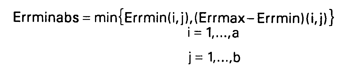
Selon un mode de réalisation particulier, la composante horizontale respectivement verticale d'un vecteur est forcée à zéro si la somme sur une ligne, respectivement une colonne, des différences entre la distortion introduite par le vecteur dont ladite composante horizontale, respectivement verticale, a été forcée à zéro et la distortion introduite par un vecteur de même composante verticale, respectivement horizontale, est inférieure à une estimation de bruit dans l'image, multipliée par un coefficient correcteur :
- composante horizontale :

- composante verticale :

- horizontal component:
- vertical component:
D'autres caractéristiques et avantages de l'invention apparaîtront à travers la description de l'exemple de réalisation non limitatif décrit dans ce qui suit et illustré à l'aide des figures parmi lesquelles :
- la figure 1 est un diagramme représentant les trames d'entrée et de sortie du présent procédé par rapport à l'axe du temps,
- la figure 2 est un diagramme bloc d'un dispositif mettant en oeuvre le procédé conforme au présent exemple de réalisation,
- la figure 3 représente un chronogramme des trames à certains points du dispositif de la figure 2,
- la figure 4 représente une image comportant des structures périodiques, ainsi qu'un exemple de vecteurs de mouvement pouvant être générés pour une telle image,
- la figure 5 représente un histogramme des erreurs d'une ligne d'une matrice d'erreur liée à une composante verticale d'un vecteur de mouvement donnée et contenant la plus petite erreur de la matrice,
- la figure 6 illustre le procédé mis en oeuvre pour tenir compte de blocs périodiques dans la détermination du champ de vecteurs de mouvement d'une image,
- la figure 7 représente deux filtres passe-bas,
- la figure 8 représente les
trames - la figure 9 représente les
trames - la figure 10 (a) représente une fonction non linéaire utilisée par le procédé de réduction de bruit temporelle récursive,
- la figure 10 (b) est un diagramme bloc d'un filtre de réduction de bruit temporelle récursive,
- la figure 11 représente un filtre spatio-temporel de type médian utilisé pour l'interpolation de la trame 1,
- la figure 12 illustre un problème lié à la présence de structures périodiques dans l'image,
- la figure 13 donne deux exemples de mise en oeuvre du filtre spatio-temporel utilisé pour l'interpolation de la trame 2,
- la figure 14 donne deux exemples de mise en oeuvre du filtre spatio-temporel utilisé pour l'interpolation de la trame 3,
- la figure 15 représente un chronogramme des trames à certains points du dispositif de la figure 2 lors du mode film, et
- la figure 16 comprend trois schémas (a,b,c) de trames par rapport au temps illustrant respectivement le mode de fonctionnement normal pour des trames vidéo, le mode de fonctionnement normal pour des trames film et le mode de fonctionnement spécifique pour des trames film.
- FIG. 1 is a diagram representing the input and output frames of the present method with respect to the time axis,
- FIG. 2 is a block diagram of a device implementing the method in accordance with this exemplary embodiment,
- FIG. 3 represents a timing diagram of the frames at certain points of the device of FIG. 2,
- FIG. 4 represents an image comprising periodic structures, as well as an example of motion vectors which can be generated for such an image,
- FIG. 5 represents a histogram of the errors of a line of an error matrix linked to a vertical component of a given motion vector and containing the smallest error of the matrix,
- FIG. 6 illustrates the method implemented to take account of periodic blocks in determining the field of motion vectors of an image,
- FIG. 7 represents two low-pass filters,
- FIG. 8 represents the
frames - FIG. 9 represents the
frames - FIG. 10 (a) represents a non-linear function used by the recursive temporal noise reduction method,
- FIG. 10 (b) is a block diagram of a recursive temporal noise reduction filter,
- FIG. 11 represents a space-time filter of the median type used for the interpolation of the
frame 1, - FIG. 12 illustrates a problem linked to the presence of periodic structures in the image,
- FIG. 13 gives two examples of implementation of the space-time filter used for the interpolation of
frame 2, - FIG. 14 gives two examples of implementation of the space-time filter used for the interpolation of
frame 3, - FIG. 15 represents a timing diagram of the frames at certain points of the device of FIG. 2 during the film mode, and
- FIG. 16 comprises three diagrams (a, b, c) of frames with respect to time respectively illustrating the normal operating mode for video frames, the normal operating mode for film frames and the specific operating mode for film frames.
L'invention sera expliquée en relation avec un procédé de conversion de fréquence d'images de télévision de 50 Hz entrelacées à 75 Hz progressives.The invention will be explained in relation to a method for converting the frequency of television images from 50 Hz interlaced to 75 Hz progressive.
Deux demandes de brevet déposées conjointement le même jour traitent d'autres aspects de ce procédé.Two patent applications filed jointly on the same day deal with other aspects of this process.
Une période est définie comme étant l'intervalle temporel permettant d'afficher une trame de sortie, soit 1/75 secondes. Un cycle est défini comme étant l'intervalle de temps nécessaire pour un cycle complet de l'algorithme, soit trois périodes ou 1/25 secondes.A period is defined as the time interval used to display an output frame,
Le procédé se répète identique à lui-même toutes les trois trames de sortie ou toutes les deux trames d'entrée. Par convention, la première trame de sortie porte le numéro 1, la deuxième trame porte le numéro 2, et ainsi de suite. Mais du fait que le traitement est cyclique, les trames 1, 4, 7 ... seront générées de façon identique; on les appellera des trames de type 1. De même, les trames 2, 5, 8 ..., respectivement les trames 3, 6, 9... seront générées de façon identique et respectivement appelées trames de type 2 et 3.The process repeats identical to itself every three output frames or every two input frames. By convention, the first output frame is
Par convention, les trames d'entrée seront numérotées par référence à la position qu'elles occupent vis-à-vis des trames de sortie. Ainsi, une trame d'entrée correspondant temporellement à une trame de sortie portera le même numéro que cette trame de sortie. Une trame d'entrée située entre deux trames de sortie portera les numéros de ces deux trames: par exemple, une trame d'entrée située entre les trames de sortie 2 et 3 sera appelée trame 2/3.By convention, the input frames will be numbered by reference to the position they occupy with respect to the output frames. Thus, an input frame corresponding temporally to an output frame will have the same number as this output frame. An input frame located between two output frames will carry the numbers of these two frames: for example, an input frame located between
La figure 1 illustre les positions respectives des trames d'entrée et de sortie.Figure 1 illustrates the respective positions of the input and output frames.
La trame d'entrée numéro 1 comporte la première ligne affichée à l'écran d'un téléviseur; elle a été indicée ligne O. Cette trame, donc la trame d'entrée impaire, est formée des ligne 0, 2, 4, ..., 624. Une trame 2/3, paire, comportera les lignes 1, 3, 5, ..., 623. La variable y représentera les numéros de ligne, croissantes du haut vers le bas de l'écran, dans le sens du balayage. La variable x sera utilisée pour désigner l'abscisse d'un pixel et croît de gauche à droite également dans le sens du balayage. t représentera le temps, normalisé de façon à ce qu'une unité temporelle représente un cycle. La trame 1 sera située au temps 0, la trame 2/3 au temps 1/2 et la trame 4 au temps 1.The
Les trames de sortie comporteront tous les numéros de ligne, puisque ce sont des trames progressives. Le signal de luminance à la position d'un pixel donné sera représenté par la variable P(x,y,t).The output frames will have all line numbers, since they are progressive frames. The luminance signal at the position of a given pixel will be represented by the variable P (x, y, t).
Avantageusement, le procédé de conversion décrit et le dispositif de mise en oeuvre ne nécessitent qu'une seule mémoire de trame. Cette contrainte s'explique par le fait que le procédé est destiné à être implémenté dans des appareils grand public fabriqués en grande série. La réduction du coût de mise en oeuvre du point de vue matériel est donc un facteur important.Advantageously, the described conversion method and the implementation device require only a single frame memory. This constraint is explained by the fact that the method is intended to be implemented in consumer devices manufactured in large series. Reducing the cost of implementation from the hardware point of view is therefore an important factor.
La figure 2 est un diagramme bloc du dispositif de mise en oeuvre de l'invention. Chaque élément sera vu en détail par la suite.FIG. 2 is a block diagram of the device for implementing the invention. Each element will be seen in detail later.
Le dispositif comporte une mémoire vive 1 organisée en FIFO et destinée à augmenter la fréquence des trames de 50 à 75 Hz, en répétant en lecture une trame sur deux. La mémoire 1 reçoit donc en entrée des trames à la fréquence de 50 Hz et fournit des trames à la fréquence de 75 Hz.The device comprises a
Le dispositif comporte d'autre part un circuit de réduction de bruit 2, comprenant deux filtres: un filtre spatial destiné à réduire principalement les bruits de type impulsionnel, et un filtre temporel récursif. Le filtre spatial reçoit les trames issues de la mémoire 1, puis transmet les trames filtrées au filtre temporel. Le filtre temporel reçoit également une trame dite trame projetée, composée d'informations de trames précédemment traitées. Le fonctionnement du filtre temporel sera vu plus en détail ultérieurement.The device also comprises a
Une trame filtrée temporellement est stockée dans une mémoire trame 3 et transmise à un interpolateur 4. L'interpolateur 4 réalise l'interpolation entre deux trames d'entrée pour fournir les trames de sortie du dispositif. L'interpolateur 4 reçoit des vecteurs de mouvement de la part d'un circuit d'estimation de mouvement 5. L'estimation de mouvement est réalisée entre la trame stockée dans la mémoire de trame 3 et la trame "courante" lue dans la mémoire 1. Un certain nombre d'informations relatives à l'estimation de mouvement sont utilisées lors de la réduction de bruit.A temporally filtered frame is stored in a
La figure 3 comporte les chronogrammes relatifs aux trames traitées par les différents éléments du dispositif de la figure 5. Les lettres identifiant chaque chronogramme correspondent aux lettres identifiant les connexions entre les éléments de cette dernière figure.FIG. 3 comprises the chronograms relating to the frames processed by the various elements of the device of FIG. 5. The letters identifying each chronogram correspond to the letters identifying the connections between the elements of this latter figure.
Une trame est représentée sous la forme d'une dent de scie correspondant au balayage de cette trame.A frame is represented in the form of a sawtooth corresponding to the scanning of this frame.
Le premier chronogramme (I) correspond aux trames d'entrée de la mémoire 1, c'est à dire aux trames entrelacées à 50 Hz. La trame 1 est impaire, la trame 2/3 est paire etc...The first timing diagram (I) corresponds to the input frames of
Le second chronogramme (A) correspond à la sortie de la mémoire 1: les trames sont relues à une vitesse de 75 Hz. La trame 1 (et les trames 4, 7 ...) est lue une fois, la lecture débutant avant même que l'écriture ne soit achevée. La trame 2/3 (et les trames 5/6, 8/9 ...) est lue deux fois.The second timing diagram (A) corresponds to the output of memory 1: the frames are re-read at a speed of 75 Hz. Frame 1 (and frames 4, 7 ...) is read once, the reading starting even before that writing is not completed.
Le troisième chronogramme (G) représente la sortie de la mémoire trame 3. Cette mémoire maintient un écart temporel d'une trame entre sa trame d'entrée et celle à sa sortie, pour que l'interpolation puisse se faire correctement. Dans ce but, la mémoire ne se comporte pas simplement comme un retard d'une trame. Si cela était le cas, la trame filtrée 2/3 serait à la fois présente à l'entrée de la mémoire et à sa sortie. C'est donc la trame filtrée 1 qui est répétée deux fois à la sortie de la mémoire de trame.The third timing diagram (G) represents the output of the
Le quatrième chronogramme (B) représente les périodes de calcul des informations fournies par l'estimateur de mouvement au reste du dispositif. Comme on le verra plus en détail par la suite, l'estimateur de mouvement se comporte différemment à chaque période d'un cycle donné. Pour les trames de type 1, des vecteurs de mouvement grossiers sont calculés (référence "MB") pour des blocs larges (appelés blocs principaux), tandis que des vecteurs de mouvement plus fins sont déterminés pour les deux autres trames (référence "SB") pour des sous-blocs des blocs principaux. Le calcul des vecteurs pour les sous-blocs se base sur les vecteurs grossiers des blocs principaux. La référence "MB1//2/3" du chronogramme indique par exemple la période de l'estimation de mouvement "grossière" entre la trame 1 et la trame 2/3.The fourth timing diagram (B) represents the periods of calculation of the information provided by the motion estimator to the rest of the device. As will be seen in more detail below, the motion estimator behaves differently at each period of a given cycle. For
Le cinquième chronogramme (C) concerne la sortie du filtre spatial du circuit de réduction de bruit. Ce filtrage se fait directement sur la trame lue dans la mémoire 1.The fifth timing diagram (C) relates to the output of the spatial filter from the noise reduction circuit. This filtering is done directly on the frame read in
Le sixième chronogramme (D) représente la trame projetée comparée par le circuit de réduction de bruit à la trame filtrée spatialement.The sixth timing diagram (D) represents the projected frame compared by the noise reduction circuit with the spatially filtered frame.
Le septième chronogramme (E) indique la sortie du filtre temporel et par conséquent l'entrée de l'interpolateur 4 et de la mémoire de trame 3.The seventh timing diagram (E) indicates the output of the time filter and therefore the input of the
Le dernier chronogramme indique la sortie de l'interpolateur et donc la sortie du dispositif en soi.The last timing diagram indicates the output of the interpolator and therefore the output of the device itself.
L'estimateur de mouvement travaille selon le procédé de comparaison par blocs hiérarchisée. Ce procédé se déroule en deux étapes. On commence par diviser l'image en blocs grossiers ou blocs principaux de 16*32 pixels dont on détermine le mouvement, puis on divise ces blocs principaux en sous-blocs pour affiner le champ des vecteurs.The motion estimator works according to the hierarchical block comparison process. This process takes place in two stages. We start by dividing the image into coarse blocks or main blocks of 16 * 32 pixels whose movement is determined, then we divide these main blocks into sub-blocks to refine the vector field.
L'estimation est effectuée pour le signal de luminance, qui contient généralement des informations suffisantes pour décrire le mouvement des objets sur l'écran. Bien entendu, il est possible d'utiliser également l'information de chrominance ou de combiner les informations de chrominance et de luminance pour l'estimation.The estimation is made for the luminance signal, which generally contains sufficient information to describe the movement of objects on the screen. Of course, it is also possible to use the chrominance information or to combine the chrominance and luminance information for the estimation.
Avant toutes choses, on procède à un sous-échantillonnage des trames d'entrée par un facteur 2 dans les directions horizontales et verticales. On divise ainsi par quatre les calculs nécessaires à l'estimation. Les trames sous-échantillonnées ne seront cependant utilisées que pour l'estimation de mouvement. L'interpolation des trames de sortie se fera à partir des trames complètes.First of all, we sub-sample the input frames by a factor of 2 in the horizontal and vertical directions. We thus divide by four the calculations necessary for the estimation. The sub-sampled frames will however only be used for motion estimation. The interpolation of the output frames will be done from the complete frames.
Ce sous-échantillonnage restreint naturellement les composantes des vecteurs de mouvement à des valeurs paires. Ceci n'est pas gênant dans le sens vertical, puisque cette contrainte est déjà imposée par l'entrelacement des trames à la diffusion.This subsampling naturally restricts the components of the motion vectors to even values. This is not annoying in the vertical direction, since this constraint is already imposed by the interlacing of the frames with the diffusion.
Lors du sous-échantillonnage, on ne gardera que les lignes impaires et les colonnes paires. On continuera cependant à repérer les points de l'image à l'aide du système de coordonnées utilisé jusqu'ici, en s'interdisant les pixels n'appartenant pas au domaine sous-échantillonné.During the sub-sampling, only the odd lines and the even columns will be kept. However, we will continue to identify the points of the image using the coordinate system used so far, avoiding pixels not belonging to the subsampled domain.
Selon le présent mode de réalisation, avant de procédér au sous-échantillonnage, on applique à la trame un filtre passe-bas destiné à supprimer les hautes fréquences spatiales, sources de superposition spectrale. Pour ce faire, en horizontal, on utilise par exemple une fenêtre triangulaire à sept coefficients :
Dans la direction verticale, on procède également à un filtrage. Comme on ne garde que les lignes impaires, cela correspond aux numéros de lignes verticalement interpolées de la trame d'entrée 1 et aux numéros des lignes d'entrée de la trame 2/3. Afin d'harmoniser les contenus spectraux des deux trames d'entrée sous-échantillonnées, on procède à un filtrage passe-bas de la trame d'entrée 2/3 :
Pour les trames de type 1, on génère des lignes impaires en utilisant une simple moyenne verticale :![]()
![]()
Les fonctions Psous - échantillonné(x,y,0) et Psous-échantillonné(x,y, ![]()
![]()
Comme cela a déjà été mentionné, le procédé d'estimation hierarchisé se comporte différemment pendant les trois périodes d'un cycle :
- pendant
la période 1, on calcule les vecteurs correspondant aux blocs principaux, représentatifs du mouvement entre les trames 1et 2/3, - pendant
la période 2, on calcule les vecteurs correspondant aux sous-blocs, représentatifs de façon plus précise du mouvement entre les trames 1et 2/3, le calcul se faisant à l'aide des vecteurs déterminés pendantla période 1, - pendant
la période 3, on calcule les vecteurs correspondant aux sous-blocs, représentatifs du mouvement entre les trames 2/3et 4. Dans ce dernier cas, le calcul se fait à partir de vecteurs de blocs intermédiaires, qui sont constitués de valeurs rafraîchies des vecteurs correspondant aux blocs principaux.
- during
period 1, the vectors corresponding to the main blocks, representative of the movement betweenframes - during
period 2, the vectors corresponding to the sub-blocks, more precisely representative of the movement between theframes period 1, - during
period 3, the vectors corresponding to the sub-blocks, representative of the movement between theframes 2/3 and 4, are calculated. In the latter case, the calculation is made from block vectors intermediaries, which consist of refreshed values of the vectors corresponding to the main blocks.
L'image est tout d'abord découpée en blocs principaux de 32*16 pixels. Comme la taille d'une image active est de 720*576 pixels pour la fréquence d'échantillonnage standard, on a ainsi 23 blocs principaux par ligne et 36 par colonne.The image is first cut into main blocks of 32 * 16 pixels. Since the size of an active image is 720 * 576 pixels for the standard sampling frequency, there are thus 23 main blocks per line and 36 per column.
Pour un bloc principal indicé (i,j) avec i compris entre 0 et 22 et j compris entre 0 et 35 et appartenant par définition à la trame d'arrivée (la trame temporellement la plus récente), donc une trame 2/3 ou équivalente, on définit l'erreur commise pour un vecteur de mouvement (u,v) par :
et My =16, taille en ordonnée d'un bloc principal.For an indexed main block (i, j) with i between 0 and 22 and j between 0 and 35 and belonging by definition to the arrival frame (the most recent time frame), therefore a 2/3 frame or equivalent, we define the error made for a motion vector (u, v) by:
and My = 16, size on the ordinate of a main block.
On calcule alors la matrice des erreurs pour chaque bloc principal: chaque élément de cette matrice correspond à une erreur liée à un vecteur de mouvement possible, soit :
Err(i,j) = (E(i,j)(u,v)) pour u= -16,-14,...,14,16;v = -4,-2,0,2,4We then calculate the error matrix for each main block: each element of this matrix corresponds to an error linked to a possible motion vector, that is:
Err (i, j) = (E (i, j) (u, v)) for u = -16, -14, ..., 14.16; v = -4, -2,0,2,4
Les composantes des vecteurs de mouvement sont paires et comprises respectivement entre -16 et +16, et -4 et +4. On compare donc le bloc principal considéré à des blocs d'une fenêtre de recherche d'une trame précédente, cette fenêtre de recherche étant située autour de la position du bloc principal rapportée à cette trame précédente. Le vecteur retenu parmi l'ensemble des vecteurs est note (u',v') et correspond au minimum de la fonction d'erreur.
Errmin=min(E(i,j)(u,v)) = Err(i,j)(u',v')
pour u= -16,-14,..., 14,16 et v= -4,-2,0,2,4The components of the motion vectors are even and between respectively -16 and +16, and -4 and +4. We therefore compare the main block considered with blocks of a search window of a previous frame, this search window being located around the position of the main block related to this previous frame. The vector retained among the set of vectors is noted (u ', v') and corresponds to the minimum of the error function.
Errmin = min (E (i, j) (u, v)) = Err (i, j) (u ', v')
for u = -16, -14, ..., 14.16 and v = -4, -2,0,2,4
Le champ de vecteurs de l'image entière est calculé en balayant, bloc par bloc, et en appliquant cette recherche à chaque bloc principal.The vector field of the entire image is calculated by scanning, block by block, and applying this search to each main block.
On procède par ailleurs lors du calcul du champ de vecteurs de niveau bloc principal à une estimation du bruit de l'image. On calcule pour ce faire une valeur supplémentaire: l'erreur maximale de la matrice :
Errmax= max(E(i,j)(u,v))
pour u= -16,-14,...,14,16;v = -4,-2,0,2,4Furthermore, during the calculation of the main block level vector field, the noise of the image is estimated. To do this, an additional value is calculated: the maximum error of the matrix:
Errmax = max (E (i, j) (u, v))
for u = -16, -14, ..., 14.16; v = -4, -2,0,2,4
Errmin représente une estimation de la somme de deux bruits: le bruit inhérent au signal de luminance, et le bruit de quantification des vecteurs de mouvement. En effet, si le vecteur de mouvement que l'on a calculé correspond bien au mouvement rée!lement présent dans l'image, Errmin sera la somme des différences de luminosité existant dans deux surfaces identiques de la taille d'un bloc principal : ces différences auront alors pour unique origine le bruit de l'image.Errmin represents an estimate of the sum of two noises: the noise inherent in the luminance signal, and the quantization noise of the motion vectors. In fact, if the motion vector that has been calculated corresponds well to the movement actually present in the image, Errmin will be the sum of the differences in brightness existing in two identical surfaces the size of a main block: these differences will then be caused only by image noise.
Par contre, si du fait de la quantification des vecteurs possibles, le mouvement est mal représenté par le vecteur calculé, alors s'ajoutera au bruit précédent une composante due à l'erreur faite sur ce vecteur : Errmin sera trop sévère pour définir le bruit réel de l'image.On the other hand, if due to the quantification of the possible vectors, the movement is badly represented by the calculated vector, then a component due to the error made on this vector will be added to the preceding noise: Errmin will be too severe to define the noise real picture.
On définit par conséquent un second estimateur, à savoir Errmax-Errmin. Il est lui aussi fonction du bruit de quantification de l'image. Sur une zone uniforme, la différence entre l'erreur maximale et l'erreur minimale provient uniquement du bruit de l'image. Si le bruit de quantification est fort, alors Errmin et Errmax sont affectés tous les deux ; on peut espérer que cet estimateur est moins sensible au bruit de quantification, éliminé par la différenciation.A second estimator is therefore defined, namely Errmax-Errmin. It is also a function of the image quantization noise. On a uniform area, the difference between the maximum error and the minimum error comes only from the noise of the image. If the quantization noise is loud, then Errmin and Errmax are both affected; we can hope that this estimator is less sensitive to the quantization noise, eliminated by differentiation.
On définit d'autre part deux estimateurs Errminabs et Noiseest :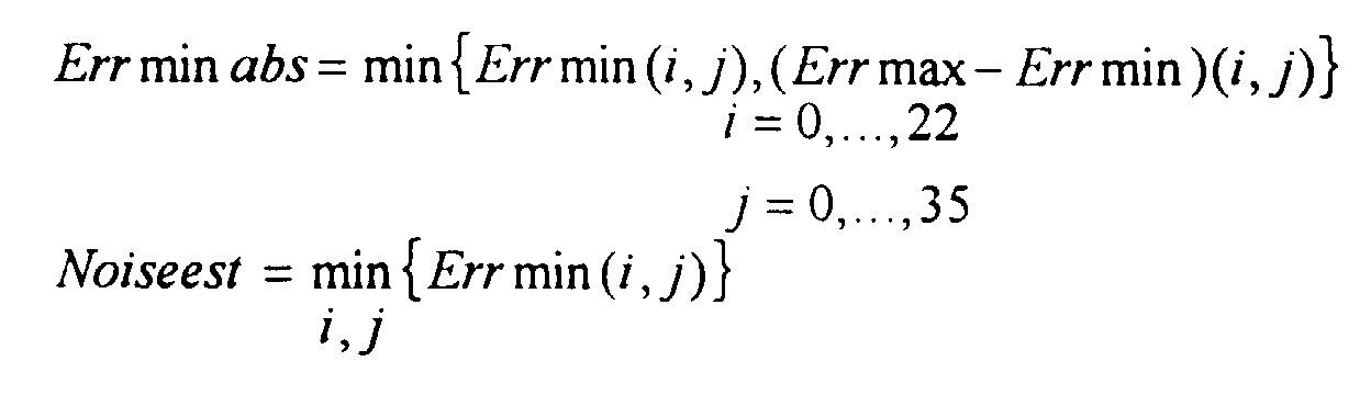
Selon une variante de réalisation, une première correction est apportée lorsque l'image comporte des zones uniformes.According to an alternative embodiment, a first correction is made when the image includes uniform areas.
Sur une zone uniforme, comme un morceau de ciel bleu, la matrice des erreurs est approximativement constante. Les fluctuations sont dues à la présence de bruit dans l'image. Le vecteur calculé par l'intermédiaire du procédé conforme à l'invention est donc imprévisible, et il peut en résulter une forte hétérogénéité du champ de vecteurs, ce qui est préjudiciable à la suite du procédé. En présence de telles hétérogénéités, on décide de forcer le vecteur correspondant à zéro.On a uniform area, like a piece of blue sky, the error matrix is approximately constant. Fluctuations are due to the presence of noise in the image. The vector calculated by means of the method according to the invention is therefore unpredictable, and it can result in a strong heterogeneity of the vector field, which is detrimental as a result of the method. In the presence of such heterogeneities, it is decided to force the vector corresponding to zero.
Ce forçage est en fait réalisé composante par composante. En effet, si on considère une frontière horizontale dans l'image (une falaise surmontée de ciel bleu par exemple), la composante u du vecteur de mouvement n'est pas fixée car les erreurs sont constantes sur chaque ligne de la matrice. On force donc cette composante à zéro. De même pour la composante v en cas de frontière verticale.This forcing is in fact carried out component by component. Indeed, if we consider a horizontal border in the image (a cliff surmounted by blue sky for example), the component u of the motion vector is not fixed because the errors are constant on each line of the matrix. We force this component to zero. Likewise for the component v in the event of a vertical border.
Selon le présent exemple de réalisation, le critère employé pour déterminer si une composante de vecteur doit être forcée à zéro est lié au niveau de bruit calculé ci-dessus.
Si Err(i,j)(0,v)-Err(i,j)(u,v) <Errminabs*seuil_x alors u = 0
Si Err(i,j)(u,0)-Err(i,j)(u,v) <Errminabs*seuil_y alors v = 0According to the present exemplary embodiment, the criterion used to determine whether a vector component must be forced to zero is linked to the noise level calculated above.
If Err (i, j) (0, v) -Err (i, j) (u, v) <Errminabs * threshold_x then u = 0
If Err (i, j) (u, 0) -Err (i, j) (u, v) <Errminabs * threshold_y then v = 0
Les valeurs seuil_x et seuil_y sont par exemple égales à des multiples de 2: 2, 4, 8...The threshold_x and threshold_y values are for example equal to multiples of 2: 2, 4, 8 ...
En clair, si la différence entre les erreurs engendrées par le vecteur de composante nulle et le vecteur trouvé par l'estimation de mouvement est du même ordre de grandeur que le bruit estimé inhérent à l'image, alors la correction est apportée.Clearly, if the difference between the errors generated by the zero component vector and the vector found by the motion estimation is of the same order of magnitude as the estimated noise inherent in the image, then the correction is made.
Selon une variante de réalisation, le critère pour déterminer si une composante horizontale est à forcer à zéro est le suivant :
Ce critère prend en compte les variations de la différence d'erreurs sur toute une ligne de la matrice d'erreurs, et non seulement la différence avec le seul vecteur dont la composante est éventuellement à forcer à zéro.This criterion takes into account the variations of the difference of errors on a whole line of the matrix of errors, and not only the difference with the only vector whose component is possibly to be forced to zero.
Détecter une ambiguïté sur une composante d'un vecteur mouvement signifie détecter qu'à priori aucune des valeurs possibles pour cette composante n'a de raison d'être choisie plus que les autres. Il faut donc examiner les erreurs liées à chacune de ces valeurs, ce qui revient à examiner toute la ligne de la matrice d'erreurs. L'incertitude est déterminée au bruit prés. Le critère utilisé est le suivant: la moyenne des différences par rapport à l'erreur du vecteur dont la composante est forcée à zéro est inférieure à un certain seuil dépendant du bruit. C'est en fait un critère de détection d'uniformité de la ligne de la matrice d'erreur.Detecting an ambiguity on a component of a motion vector means detecting that a priori none of the possible values for this component has a reason to be chosen more than the others. It is therefore necessary to examine the errors linked to each of these values, which amounts to examining the entire line of the error matrix. Uncertainty is determined at near noise. The criterion used is as follows: the average of the differences with respect to the error of the vector whose component is forced to zero is less than a certain noise-dependent threshold. It is in fact a criterion for detecting uniformity of the line of the error matrix.
Le critère pour une composante verticale est similaire :
Le forçage à zéro conforme à cette variante permet de détecter les ambiguïtés sur la composante verticale ou encore horizontale d'un vecteur de mouvement, et ceci dans une limite de précision qui est liée par une fonction strictement croissante à la quantité de bruit dans l'image.Forcing to zero in accordance with this variant makes it possible to detect ambiguities on the vertical or even horizontal component of a motion vector, and this within a limit of precision which is linked by a strictly increasing function to the amount of noise in the image.
Ceci ne peut se faire qu'en prenant en compte toute la ligne (respectivement colonne) de la matrice d'erreurs contenant le minimum par l'examen des variations au sein de cette ligne (respectivement colonne).This can only be done by taking into account the entire row (respectively column) of the error matrix containing the minimum by examining the variations within this row (respectively column).
Une correction est également apportée lorsque l'image contient des structures périodiques.A correction is also made when the image contains periodic structures.
Le problème posé par ce genre de structure a déjà été abordé en introduction. Les figures 4 et 12 permettent cependant de le préciser pour mieux comprendre la détection et la correction envisagées.The problem posed by this kind of structure has already been addressed in the introduction. Figures 4 and 12 however make it possible to specify it to better understand the detection and the correction envisaged.
Le bloc en grisé de la figure 4 représente le bloc dont le mouvement est à déterminer, tandis que les deux blocs en pointillé représentent deux blocs dans l'image de référence donnant lieu à un minimum d'erreur dans la matrice des erreurs. Un vecteur incorrect générera des défauts très perceptibles lors de l'interpolation des trames de sortie.The shaded block in FIG. 4 represents the block whose movement is to be determined, while the two dotted blocks represent two blocks in the reference image giving rise to a minimum of error in the error matrix. An incorrect vector will generate very noticeable faults when interpolating the output frames.
Ces défauts sont illustrés en gros plan par la figure 12, où le vrai mouvement d'un bloc entre deux trames de parité opposée est donné par un vecteur ayant une composante horizontale de +2. Si le vecteur de mouvement est nul, alors les défauts illustrés dans la partie droite de la figure apparaîssent lors de l'entrelaçage. La hauteur des lignes a été exagérée pour bien montrer les défauts.These defects are illustrated in close-up in FIG. 12, where the true movement of a block between two frames of opposite parity is given by a vector having a horizontal component of +2. If the motion vector is zero, then the faults illustrated on the right side of the figure appear during interlacing. The height of the lines has been exaggerated to show the faults.
Dans le cadre du présent exemple de réalisation, on se restreindra à une périodicité horizontale (par exemple un zèbre à rayures verticales), étant donné que la taille des blocs principaux et la gamme des composantes verticales possibles des vecteurs de mouvement rendent peu probable ce type d'erreur dans la direction verticale. La gamme des composantes verticales est trop restreinte pour permettre une détection ou une correction efficace. Néanmoins, l'homme du métier pourra facilement adapter la correction décrite ci-après à notamment une périodicité verticale.In the context of the present exemplary embodiment, we will restrict ourselves to a horizontal periodicity (for example a zebra with vertical stripes), since the size of the main blocks and the range of possible vertical components of the motion vectors make this type unlikely. error in the vertical direction. The range of vertical components is too small to allow effective detection or correction. However, those skilled in the art can easily adapt the correction described below to in particular a vertical periodicity.
Deux étapes seront maintenant abordées: la détection, puis la correction de ce type d'erreur.Two steps will now be discussed: detecting and then correcting this type of error.
La détection de ce type de défaut est effectuée à partir de la matrice des erreurs Err. En effet, la ligne contenant le minimum des éléments de la matrice contiendra aussi un ou plusieurs minima secondaires comme expliqué ci-dessus.The detection of this type of fault is carried out from the Err error matrix. Indeed, the line containing the minimum of the elements of the matrix will also contain one or more secondary minima as explained above.
Tout d'abord, on extrait de la matrice la ligne (Row(u)) des erreurs contenant le minimum avec -16< =u< = +16. Soit umin l'indice du minimum dans Row(u). On commence par détecter le minimum secondaire. Il se caractérise comme étant un minimum local :
Row(u-1)> Row(u) et Row(u + 1) > Row(u)First, we extract from the matrix the row (Row (u)) of errors containing the minimum with -16 <= u <= +16. Let umin be the minimum index in Row (u). We start by detecting the secondary minimum. It is characterized as being a local minimum:
Row (u-1)> Row (u) and Row (u + 1)> Row (u)
Parmi les minima secondaires répondant au critère, on ne retient que le plus petit. Soit Usec_min son indice dans la ligne Row(u). On détecte ensuite le maximum secondaire, situé entre les positions umin et usec_min. Il se caractérise comme étant un maximum local :
Row(u-1) < Row(u) et Row(u + 1) < Row(u)Among the secondary minima meeting the criterion, only the smallest is retained. Let Usec_min be its index in the Row (u) row. We then detect the secondary maximum, located between the umin and usec_min positions. It is characterized as being a local maximum:
Row (u-1) <Row (u) and Row (u + 1) <Row (u)
Parmi les maxima secondaires répondant au critère, on ne retient que le plus grand. Soit usec_max son indice dans Row(u).Among the secondary maxima meeting the criterion, only the largest is retained. Let usec_max be its index in Row (u).
L'histogramme de la figure 5 représente un exemple caractéristique d'une telle situation.The histogram in FIG. 5 represents a characteristic example of such a situation.
On soumet le minimum secondaire et le minimum absolu, ainsi que le maximum secondaire à deux tests supplémentaires pour s'assurer de la présence d'une structure périodique :
- les deux minima doivent être proches en valeur (C1),
- la différence entre eux et le maximum secondaire doit être significative par rapport au niveau de bruit courant (C2).
- the two minima must be close in value (C1),
- the difference between them and the secondary maximum must be significant compared to the current noise level (C2).
Ces précautions doivent être prises pour éviter que ne soit considéré comme périodique un bloc principal au bord du zèbre. En effet, un bloc principal peut être à cheval sur le bord du zèbre, une moitié appartenant à l'animal, l'autre à la savane. Ce bloc peut donner un minimum d'erreur, qui sera cependant supérieur aux minima liés à une périodicité. On évite aussi ainsi de considérer comme périodique une matrice d'erreur bruitée.These precautions must be taken to avoid being considered as periodic a main block at the edge of the zebra. Indeed, a main block can be astride the edge of the zebra, one half belonging to the animal, the other to the savannah. This block can give a minimum of error, which will however be higher than the minima linked to a periodicity. One thus also avoids considering as periodic a noisy error matrix.
On notera:
- Errmin = Row(umin)
- Errmax = Row(umax)
- Err_sec_min = Row(usec_min)
- Err_sec_max = Row(usec_max)
- Errmin = Row (umin)
- Errmax = Row (umax)
- Err_sec_min = Row (usec_min)
- Err_sec_max = Row (usec_max)
On impose les conditions suivantes :
- (C1) Err_sec_min - Errmin < a*Errmax
- (C2) Err_sec_max - Err_sec_min > b*Errminabs
- (C3) Errmax > c*Errminabs
- (C1) Err_sec_min - Errmin <a * Errmax
- (C2) Err_sec_max - Err_sec_min> b * Errminabs
- (C3) Errmax> c * Errminabs
Selon le présent exemple, on prendra
- a=0.5
- b=2
- c=4
- a = 0.5
- b = 2
- c = 4
Une ligne d'erreur vérifiant toutes les conditions sera issue d'une matrice associée à un bloc contenant vraisemblablement une structure périodique.An error line verifying all the conditions will come from a matrix associated with a block probably containing a periodic structure.
Selon une variante de réalisation, on combine uniquement les deux premières conditions.According to an alternative embodiment, only the first two conditions are combined.
Il s'agit ensuite de corriger le vecteur associé à ce bloc principal.The next step is to correct the vector associated with this main block.
Pour cela, il ne suffit pas de prendre en compte uniquement le bloc principal périodique. Si l'on se rapporte au dessin du zèbre, en supprimant par la pensée toute la partie de l'animal qui n'est pas comprise dans le bloc principal, on obtient un rectangle avec des rayures verticales. En cherchant à quelle. partie de l'image précédente correspond ce rectangle, on trouvera plusieurs rectangles rayés possibles, sans pouvoir décider lequel devra être pris en compte. Pour faire ce choix, on procède à l'agrandissement progressif du bloc principal pour lever l'incertitude. Le procédé est illustré par la figure 6, où les blocs en grisé sont les blocs périodiques d'une ligne de l'image.For this, it is not enough to take into account only the periodic main block. If we refer to the drawing of the zebra, by deleting by thought all the part of the animal which is not included in the main block, we get a rectangle with vertical stripes. By looking at what. part of the previous image corresponds to this rectangle, we will find several possible striped rectangles, without being able to decide which one should be taken into account. To make this choice, the main block is gradually enlarged to remove the uncertainty. The process is illustrated in Figure 6, where the shaded blocks are the periodic blocks of a line in the image.
Dans une ligne donnée, la détection d'un bloc principal périodique va signaler que l'on a trouvé toute une zone de l'image contenant une structure périodique. On ne retiendra pas tout de suite le vecteur de mouvement de ce bloc principal; on stockera par contre la matrice d'erreur correspondant à ce bloc.In a given line, the detection of a periodic main block will signal that an entire area of the image containing a periodic structure has been found. We will not immediately retain the motion vector of this main block; on the other hand, the error matrix corresponding to this block will be stored.
On passe au bloc principal suivant sur la même ligne. S'il est lui aussi périodique, on stocke à nouveau sa matrice d'erreur. On finira par arriver à la fin de la structure périodique, en l'occurrence le bord droit du zèbre.We move to the next main block on the same line. If it is also periodic, we store its error matrix again. We will eventually arrive at the end of the periodic structure, in this case the right edge of the zebra.
Soient (i1,J1) les coordonnées du premier bloc principal périodique rencontré, et (i2,J1) celles du dernier. On procède au cumul membre à membre de toutes les matrices stockées. On obtient une matrice dont les composantes vaudront :
On aurait obtenu la même matrice d'erreurs si on avait appliqué l'algorithme de base à un bloc prinçipal de largeur (i2-i1 + 1) fois la largeur d'un bloc principal unique. La matrice d'erreur a bien évidemment la même taille.We would have obtained the same matrix of errors if we had applied the basic algorithm to a main block of width (i2-i1 + 1) times the width of a single main block. The error matrix is obviously the same size.
Cette matrice ne suffit pas encore pour déterminer le bon vecteur de mouvement. Il faut considérer les blocs au début et à la fin de la structure périodique. En effet, ces blocs contiennent en général le bord de la zone périodique en mouvement et permettent donc de lever l'ambiguité des informations contenues dans la matrice d'erreur.This matrix is not yet sufficient to determine the correct motion vector. You have to consider the blocks at the beginning and at the end of the periodic structure. Indeed, these blocks generally contain the edge of the periodic zone in motion and therefore make it possible to remove the ambiguity of the information contained in the error matrix.
Après avoir déterminé la matrice ci-dessus, on procède de la manière suivante :
- on considère les vecteurs des deux blocs principaux en début et fin de la structure périodique. Pour chacun, on extrait de la matrice Sum l'erreur correspondante. Le vecteur dont l'erreur est la plus petite sera retenu,
- si ce vecteur ne correspond pas à un minimum local de sa ligne de la matrice d'erreur Sum, on sélectionne le minimum de la matrice d'erreur et on retient le vecteur correspondant,
- enfin, pour obtenir un cohérence verticale entre les blocs périodiques adjacents, on teste si un des blocs immédiatement supérieurs à cette rangée de blocs périodiques est également périodique et dans ce cas, on retient son vecteur, à condition toutefois qu'il corresponde bien à un minimum dans la ligne de la matrice d'erreur.
- we consider the vectors of the two main blocks at the beginning and end of the periodic structure. For each, we extract from the Sum matrix the corresponding error. The vector with the smallest error will be retained,
- if this vector does not correspond to a local minimum of its row of the error matrix Sum, we select the minimum of the error matrix and we retain the corresponding vector,
- finally, to obtain a vertical coherence between the adjacent periodic blocks, one tests if one of the blocks immediately superior to this row of periodic blocks is also periodic and in this case, one retains its vector, provided however that it corresponds well to a minimum in the row of the error matrix.
Le vecteur retenu sera ainsi le vecteur utilisé pour l'ensemble des blocs de la structure périodique.The vector selected will thus be the vector used for all the blocks of the periodic structure.
Après avoir effectué la détermination des vecteurs et éventuellement la première et ou la seconde correction, on obtient un champ de vecteurs noté :
![]()
![]()
Cette phase du procédé est utilisée deux fois de suite, pendant les périodes 2 et 3.This phase of the process is used twice in succession, during
Il s'agit d'essayer de caractériser plus finement le mouvement en attribuant des vecteurs à des éléments plus petits: les sous-blocsous-blocs (qui, selon le présent exemple ont une taille de 4*4 pixels). Ceci permettra d'obtenir une meilleure adéquation du champ de vecteurs aux bords d'objets mobiles.It is a question of trying to characterize more finely the movement by attributing vectors to smaller elements: the sub-blocks (which, according to the present example have a size of 4 * 4 pixels). This will allow better matching of the vector field to the edges of moving objects.
Selon le présent exemple, il y a 180 sous-blocsous-blocs dans une largeur d'image et 144 sous-blocs en hauteur.According to the present example, there are 180 sub-sub-blocks in an image width and 144 sub-blocks in height.
Conformément au présent exemple de réalisation, on ne recalcule pas l'ensemble des erreurs associées à la gamme entière de vecteurs de mouvements possibles comme cela a été fait pour les blocs principaux. On choisit pour chaque sous-blocs des vecteurs candidats parmi les vecteurs des blocs principaux et on détermine l'erreur générée par chacun de ces vecteurs candidats.In accordance with the present exemplary embodiment, the set of errors associated with the entire range of possible motion vectors is not recalculated as has been done for the main blocks. One chooses for each sub-blocks candidate vectors among the vectors of the main blocks and one determines the error generated by each of these candidate vectors.
Dans le cadre du présent exemple, les vecteurs candidats pour un sous-bloc sont les vecteurs des quatre blocs principaux les plus proches de ce sous-bloc. Le vecteur engendrant l'erreur la plus faible sera attribué au sous-bloc.In the context of this example, the candidate vectors for a sub-block are the vectors of the four main blocks closest to this sub-block. The vector generating the lowest error will be assigned to the sub-block.
Le fait d'utiliser des vecteurs candidats associés à des blocs principaux adjacents au bloc contenant le sous-bloc considéré permet de déterminer précisément les bords des objets mobiles, et par conséquent les frontières des zones de mouvement uniforme: si le bord d'un objet en mouvement dépasse juste un peu dans un bloc principal, le vecteur trouvé pour ce dernier sera un vecteur indiquant l'arrière-plan et non l'objet en mouvement, parce que la plus grande partie des pixels de ce bloc principal appartiennent à cet arrière-plan, dont le mouvement peut être différent de celui de l'objet. Par conséquent, le bord de l'objet ne sera pas reconstitué de manière correcte.The fact of using candidate vectors associated with main blocks adjacent to the block containing the sub-block considered makes it possible to precisely determine the edges of the mobile objects, and consequently the borders of the zones of uniform movement: if the edge of an object in movement just exceeds a little in a main block, the vector found for the latter will be a vector indicating the background and not the moving object, because most of the pixels of this main block belong to this rear -plan, whose movement can be different from that of the object. Therefore, the edge of the object will not be reconstructed correctly.
Par contre, si pour les sous-blocs du bord de l'objet, on considère aussi les vecteurs des blocs principaux adjacents, le mouvement de ces sous-blocs sera correctement estimé, puisqu'au moins un des blocs principaux adjacents fera partie de l'objet en question.On the other hand, if for the sub-blocks of the edge of the object, the vectors of the adjacent main blocks are also considered, the movement of these sub-blocks will be correctly estimated, since at least one of the adjacent main blocks will be part of the object in question.
On cherche à déterminer le champ de vecteurs minimisant la différence des luminances des sous-blocs entre les trames 1 et 2/3. Cependant, c'est la trame de sortie 2 qui sera finalement affichée. Pour améliorer la précision, on considère par conséquent les sous-blocs comme faisant partie de cette trame 2.We seek to determine the vector field minimizing the difference in the luminances of the sub-blocks between
Pour chaque sous-bloc de la trame 2, on détermine quatre blocs principaux adjacents de la manière suivante: on projette orthogonalement le sous-bloc sur la trame 2/3 (voir figure 8). Les quatre blocs les plus proches seront alors choisis comme suit :For each sub-block of
Si on parle du sous-bloc (i,j) (0<i<180, 0<j<144), on dira que les 4 blocs principaux pertinents sont :
Si imod8< 4 alors i' =-1 sinon i'= 1
Si jmod4< 2 alors j' =-1 sinon j'= 1
Rel(i,j) (1) = MB(i ∨ 8, j ∨ 4)
Rel(i,j) (2) = MB(i ∨ 8 + i', j ∨ 4)
Rel(i,j) (3) = MB(i ∨ 8, j ∨ 4 + j')
Rel(i,j) (4) = MB(i ∨ 8 + i', j ∨ 4 + j')
où le quotient de la division euclidienne de a par b est noté a∨b et son reste amodb.If we talk about the sub-block (i, j) (0 <i <180, 0 <j <144), we will say that the 4 main relevant blocks are:
If imod8 <4 then i '= -1 otherwise i' = 1
If jmod4 <2 then j '= -1 otherwise j' = 1
Rel (i, j) (1) = MB (i ∨ 8, j ∨ 4)
Rel (i, j) (2) = MB (i ∨ 8 + i ', j ∨ 4)
Rel (i, j) (3) = MB (i ∨ 8, j ∨ 4 + j ')
Rel (i, j) (4) = MB (i ∨ 8 + i ', j ∨ 4 + j')
where the quotient of the Euclidean division of a by b is noted a∨b and its remainder amodb.
Une fois les vecteurs candidats choisis, il faut les comparer entre eux. Comme indiqué plus haut, le sous-bloc fait partie de la trame affichée. Le vecteur du bloc principal en question est donc mis à l'échelle. On commence par en calculer les 2/3, et on arrondit le résultat. On obtient ainsi le vecteur de mouvement entre la trame 1 et la trame 2. Le vecteur restant correspond au mouvement entre la trame 2 et la trame 2/3. Si on appelle ces deux vecteurs respectivement rear vector et front vector, on a :
On calcule ensuite les quatre erreurs associées à ces quatre vecteurs :
Le vecteur du sous-bloc sera le vecteur donnant une erreur minimale. En balayant tous les sous-blocs, on obtient un champ de vecteurs noté Raw(i,j).The vector of the sub-block will be the vector giving a minimum error. By scanning all the sub-blocks, we obtain a vector field denoted Raw (i, j).
Selon une variante de réalisation, les composantes des vecteurs de ce champ sont soumises à un filtrage médian pour éliminer les valeurs aberrantes: en effet, une petite erreur sur un sous-bloc est moins visible qu'une hétérogénéité locale du champ de vecteurs.According to an alternative embodiment, the components of the vectors of this field are subjected to a median filtering to eliminate the outliers: indeed, a small error on a sub-block is less visible than a local heterogeneity of the vector field.
Soient :
a=(1 0)•Raw(i-1,j); a'=(0 1)•Raw(i-1,j)
b=(1 0)•Raw(i,j); b'=(0 1)•Raw(i,j)
c =(1 0)•Raw(i+1,j); c'=(0 1)•Raw(i+1,j) Let:
a = (1 0) • Raw (i-1, j) ; a '= (0 1) • Raw (i-1, j)
b = (1 0) • Raw (i, j) ; b '= (0 1) • Raw (i, j)
c = (1 0) • Raw (i + 1, j) ; c '= (0 1) • Raw (i + 1, j)
Le champ de vecteurs s'écrit alors
Le filtrage médian est donc réalisé, pour un sous-bloc donné, en tenant compte du vecteur précédemment calculé pour ce sous-bloc et des vecteurs des sous-blocs horizontalement adjacents.The median filtering is therefore carried out, for a given sub-block, taking into account the vector previously calculated for this sub-block and the vectors of the horizontally adjacent sub-blocks.
On obtient donc un champ de vecteurs pour des sous-blocs de 4*4 pixels.We thus obtain a vector field for sub-blocks of 4 * 4 pixels.
On définit également pour chaque sous-bloc l'erreur associée au vecteur choisi. Cette erreur est une mesure de la confiance accordée à chaque vecteur de mouvement. L'erreur s'écrit :
Comme cela a été fait pour la trame 2, un calcul de vecteurs au niveau des sous-blocs est entrepris pour la trame 3, en estimant le mouvement entre les trames 2/3 et 4. Cependant, le calcul est différent de celui précédemment mis en oeuvre. En effet, selon le présent exemple de réalisation, on ne calcule pas de vecteurs de mouvement pour des blocs principaux entre les trames 2/3 et 4, ceci pour des raisons d'économie de lignes à retard. En effet, s'il fallait calculer pour la trame 3 à la fois les vecteurs des blocs principaux et ceux des sous-blocs adjacents, il faudrait, pour un sous-bloc donné, avoir calculé les vecteurs des tous les blocs principaux adjacents, et cela introduirait un retard correspondant approximativement au nombre de lignes contenu dans une rangée de blocs principaux.As was done for
Les vecteurs des sous-blocs pour la trame 3 seront calculés à partir du champ de vecteurs précédemment calculé pour les blocs principaux entre les trames 1 et 2/3. Ceci pose des problèmes en cas de mouvements rapides, étant donné que les vecteurs des sous-blocs seront alors calculés à partir de vecteurs ne reflétant plus le mouvement réel.The vectors of the sub-blocks for
Selon le présent exemple de réalisation, on rafraîchit les informations concernant les blocs principaux en créant un champ de vecteurs pour des blocs dits bloc intermédiaires, dont la taille est, justement, intermédiaire entre celle d'un bloc principal et celle d'un sous-bloc.According to the present exemplary embodiment, the information concerning the main blocks is refreshed by creating a vector field for so-called intermediate block blocks, the size of which is, precisely, intermediate between that of a main block and that of a sub- block.
Selon le présent exemple de réalisation, les blocs intermédiaires ont une taille de 32 pixels par 4 lignes: ils ont la largeur d'un bloc principal et la hauteur d'un sous-bloc. On calcule, à partir des trames 2/3 et 4 et du champ de vecteurs des blocs principaux déterminé pour les trames 1 et 2/3, le champ de vecteurs à résolution spatiale moyenne associé à ces blocs intermédiaires. On en déduira dans un second temps le champ de vecteurs des sous-blocs. L'on voit que si le champ de vecteurs déterminé entre les trames 1 et 2/3 est pris comme source de vecteurs candidats, les calculs d'erreur seront néanmoins effectués à partir de l'information des trames 2/3 et 4.According to the present exemplary embodiment, the intermediate blocks have a size of 32 pixels by 4 lines: they have the width of a main block and the height of a sub-block. One calculates, from
De même que pour les sous-blocs de la trame 2, on considère que les calculs sont effectués pour des blocs intermédiaires appartenant à la trame de sortie, à savoir la trame 3. Comme précédemment, on sera amené à décomposer les vecteurs de mouvement à appliquer aux blocs intermédiaires en deux vecteurs. Ainsi, pour un vecteur (u,v), on déterminera deux vecteurs Front et Rear comme suit :
Front = ![]()
Rear = (u, v) - FrontAs for the sub-blocks of
Front = ![]()
Rear = (u, v) - Front
L'erreur associée au vecteur de mouvement (u,v) pour un block intermédiaire (i,j) s'écrira :
Pour un bloc intermédiaire donné de la trame 3, on détermine le bloc principal qui lui correspond: c'est le bloc principal qui, projeté orthogonalement sur la trame 3, contient ce bloc intermédiaire.For a given intermediate block of
On détermine un certain nombre de vecteurs candidats pour un bloc intermédiaire (i,j) donné :
- le vecteur du bloc principal correspondant,
- le vecteur déduit du vecteur du bloc principal ci-dessus en modifiant sa composante horizontale d'un pas de quantification dans le sens positif,
- le vecteur déduit du bloc principal ci-dessus en modifiant sa composante horizontale d'un pas de quantification dans le sens négatif,
- le vecteur du bloc principal le plus proche (au-dessus ou en-dessous) du bloc intermédiaire,
- le vecteur déduit du bloc principal ci-dessus en modifiant sa composante horizontale d'un pas de quantification dans le sens positif,
- le vecteur déduit du bloc principal ci-dessus en modifiant sa composante horizontale d'un pas de quantification dans le sens négatif.
- the vector of the corresponding main block,
- the vector deduced from the vector of the main block above by modifying its horizontal component by a quantization step in the positive direction,
- the vector deduced from the main block above by modifying its horizontal component by a quantization step in the negative direction,
- the vector of the main block closest (above or below) to the intermediate block,
- the vector deduced from the main block above by modifying its horizontal component by a quantization step in the positive direction,
- the vector deduced from the main block above by modifying its horizontal component by a quantization step in the negative direction.
Selon le présent exemple de réalisation, les six vecteurs candidats seront donc :
Si jmod4 < 2 alors j' = -1 sinon j' = 1
Rel IB (i,j)(1) = MB(i,j∨4)


If jmod4 <2 then j '= -1 otherwise j' = 1
Rel IB (i, j) (1) = MB (i, j∨4)
Les second et troisième vecteurs ont même composante verticale que le premier vecteur, les composantes horizontales étant modifiées. De même, les cinquième et sixième vecteurs ont la même composante verticale que le quatrième vecteur, les composantes horizontales étant modifiées. Ce choix est dû à la taille des blocs intermédiaires, qui n'ont que deux lignes de hauteur.. Si on avait choisi des blocs intermédiaires de taille verticale plus importante, il aurait été envisageable d'effectuer une correction de la composante verticale. Mais ici, avec seulement deux lignes par bloc intermédiaire, il est difficile de déterminer de manière fiable une composante verticale et donc à fortiori de la corriger.The second and third vectors have the same vertical component as the first vector, the horizontal components being modified. Likewise, the fifth and sixth vectors have the same vertical component as the fourth vector, the horizontal components being modified. This choice is due to the size of the intermediate blocks, which have only two lines of height. If we had chosen intermediate blocks of larger vertical size, it would have been possible to carry out a correction of the vertical component. But here, with only two lines per intermediate block, it is difficult to reliably determine a vertical component and therefore a fortiori to correct it.
On calcule alors l'erreur associée à chacun des six vecteurs, et ce pour chaque bloc intermédiaire. Le vecteur retenu pour un bloc intermédiaire parmi les six vecteurs candidats est celui donnant l'erreur minimale.The error associated with each of the six vectors is then calculated for each intermediate block. The vector retained for an intermediate block among the six candidate vectors is that giving the minimum error.
Selon une variante de réalisation, on supprime la correction sur les composantes horizontales.. Ceci permet d'éviter d'engendrer de trop fortes discontinuités dans le champ de vecteurs en cas d'images bruitées.According to an alternative embodiment, the correction on the horizontal components is eliminated. This makes it possible to avoid generating too much strong discontinuities in the vector field in the event of noisy images.
On obtient finalement un champ de vecteurs à résolution spatiale moyenne note IB(i,j).Finally, we obtain a vector field with average spatial resolution note IB (i, j).
La dernière étape de l'estimation de mouvement de la trame 3 consiste à déterminer un champ de vecteurs de niveau sous-bloc à partir du champ de vecteurs aux blocs intermédiaires. On attribuera naturellement un sous-bloc au bloc intermédiaire dont il fait partie. Selon le présent exemple, deux vecteurs candidats sont déterminés pour chaque sous-bloc: le premier vecteur candidat est celui du bloc intermédiaire dont fait partie le sous-bloc, tandis que le second vecteur est celui du bloc intermédiaire adjacent tel que défini ci-dessous.The last step of the motion estimation of
Pour un sous-bloc de coordonnées (i,j), les deux vecteurs candidats seront :
Si imod8 < 4 alors 1' =-1 sinon i' = 1
Rel(i,j) (1) = IB(i ∨ 8, j ∨ 4)
Rel(i,j) (2) = IB(i ∨ 8 + i', j ∨ 4)For a coordinate sub-block (i, j), the two candidate vectors will be:
If imod8 <4 then 1 '= -1 otherwise i' = 1
Rel (i, j) (1) = IB (i ∨ 8, j ∨ 4)
Rel (i, j) (2) = IB (i ∨ 8 + i ', j ∨ 4)
On calculera donc les vecteurs :
Puis les erreurs :

Le vecteur donnant la plus petite erreur sera retenu.The vector giving the smallest error will be retained.
On procède également à un filtrage médian du champ de vecteurs (SB3(i,j)) obtenu, et on calculera le champ d'erreurs (Err3(i,j)) correspondant.We also carry out a median filtering of the vector field (SB 3 (i, j)) obtained, and we will calculate the corresponding error field (Err 3 (i, j)).
La réduction du bruit comprend deux étapes :
- une réduction de bruit spatiale,
- une réduction de bruit temporelle compensée en mouvement.
- reduction of spatial noise,
- a temporal noise reduction compensated in motion.
La première étape fait appel à l'information contenue dans une seule trame, tandis que la seconde étape fait appel à l'information contenue dans plusieurs, en l'occurrence deux, trames successives.The first step uses the information contained in a single frame, while the second step uses the information contained in several, in this case two, successive frames.
Dans ce qui suit, seul le filtrage de la luminance sera décrit.In the following, only the filtering of the luminance will be described.
Dans le cadre du présent exemple, le filtrage spatial de la chrominance n'est pas considéré comme nécessaire, les échantillons de chrominance étant trop éloignés les uns des autres pour que le filtre, médian de type directionnel ait un sens. Il est bien évident que la chrominance pourra également être filtrée, notamment si l'information de chrominance est plus dense, notamment si elle avait une résolution identique à celle de la luminance.In the context of the present example, the spatial filtering of the chrominance is not considered to be necessary, the chrominance samples being too far apart from each other for the median filter of directional type to have any meaning. It is obvious that the chrominance can also be filtered, in particular if the chrominance information is more dense, in particular if it had a resolution identical to that of the luminance.
Le filtrage temporel de la chrominance se déduit directement de celui de la luminance en considérant des trames d'entrée dont la taille est divisée par le facteur de sous-échantillonnage de la chrominance, (soit par 2 dans la direction des abscisses x pour un format d'entrée 4:2:2). Il faut également diviser la composante x des vecteurs de mouvement par ce même facteur.The temporal filtering of the chrominance is deduced directly from that of the luminance by considering input frames whose size is divided by the factor of sub-sampling of the chrominance, (either by 2 in the direction of the x-coordinates for a format input 4: 2: 2). We must also divide the x component of the motion vectors by this same factor.
La réduction spatiale de bruit est destinée à réduire le bruit impulsionnel dans les trames d'entrée.Spatial noise reduction is intended to reduce impulse noise in the input frames.
Selon le présent exemple de réalisation, le filtre spatial est un filtre médian directionnel, qui posséde l'avantage de ne pas dégrader les fronts et les textures fines d'une image. Un simple filtrage linéaire ou médian n'aurait pas cet avantage.According to the present exemplary embodiment, the spatial filter is a directional median filter, which has the advantage of not degrading the edges and the fine textures of an image. Simple linear or median filtering would not have this advantage.
Le filtrage médian directionnel est réalisé ici sur trois pixels: le pixel "courant", ainsi que deux pixels adjacents situés sur une même droite passant par le pixel courant. Compte tenu de ces restrictions, quatre directions de filtrage sont possibles: horizontale, verticale et deux diagonales.The directional median filtering is carried out here on three pixels: the "current" pixel, as well as two adjacent pixels located on the same straight line passing through the current pixel. Given these restrictions, four filtering directions are possible: horizontal, vertical and two diagonals.
Le choix de la direction à considérer est fait en fonction de la corrélation existant entre les trois pixels d'une même direction.The choice of direction to be considered is made according to the correlation existing between the three pixels of the same direction.
Le tableau suivant représente le pixel courant (X22) entouré de ses pixels adjacents :
La direction horizontale (appelée d1) passe par les pixels X21, X22 et X23.The horizontal direction (called d1) passes through the pixels X21, X22 and X23.
La direction verticale (appelée d2) passe par les pixels X12, X22 et X32.The vertical direction (called d2) passes through the pixels X12, X22 and X32.
La première direction diagonale (d3) passe par les pixels X31, X22 et X13.The first diagonal direction (d3) passes through the pixels X31, X22 and X13.
La seconde direction diagonale (d4) passe par les pixels X11, X22 et X23.The second diagonal direction (d4) passes through the pixels X11, X22 and X23.
Les coefficients de correlation associés à chacune des directions sont respectivement notées c1 à c4 et les valeurs filtrées m1 à m4.
- Selon d1:
c1 = min(|x21- x22|,|x23 - x22|)
m1 = med(x21,x22,x23) - Selon d2:
c2 = min(|x12-x22|,|x32-x22|)
m2 = med(x12,x22,x32) - Selon d3:
c3 = min(|x13-x22|,|x31- x22|)
m3 = med(x13,x22,x31) - Selon d4:
c4 = min(|x11-x22|,|x33-x22|)
m4=med(x11,x22,x33)
- According to d1:
c1 = min (| x21- x22 |, | x23 - x22 |)
m1 = med (x21, x22, x23) - According to d2:
c2 = min (| x12-x22 |, | x32-x22 |)
m2 = med (x12, x22, x32) - According to d3:
c3 = min (| x13-x22 |, | x31- x22 |)
m3 = med (x13, x22, x31) - According to d4:
c4 = min (| x11-x22 |, | x33-x22 |)
m4 = med (x11, x22, x33)
La direction pour laquelle le coefficient de corrélation est le plus faible sera retenue.The direction with the lowest correlation coefficient will be used.
D'autres fonctions de corrélation peuvent également être choisies. De même, le filtrage peut être réalisé sur plus de trois pixels ou dans plus de trois directions, si la fenêtre utilisée le permet.Other correlation functions can also be chosen. Similarly, filtering can be carried out on more than three pixels or in more than three directions, if the window used allows it.
Un intérêt non négligeable de l'estimation de mouvement est qu'elle permet l'application de procédés de réduction de bruit compensés en mouvement.A significant advantage of motion estimation is that it allows the application of motion-compensated noise reduction methods.
On part de l'hypothèse que le bruit perturbant une image de télévision est sensiblement d'espérance mathématique nulle, c'est à dire que sa moyenne temporelle sur plusieurs images tend vers zéro. On peut donc réduire les composantes à haute fréquence de ce bruit en réalisant un filtrage passe-bas temporel de l'image.We start from the assumption that the noise disturbing a television image is substantially of zero mathematical expectation, that is to say that its time average over several images tends towards zero. It is therefore possible to reduce the high frequency components of this noise by carrying out a temporal low-pass filtering of the image.
Un procédé de filtrage connu consiste à réaliser un filtrage numérique récurrent pixel à pixel. Ce procédé comprend la mémorisation, pour chaque pixel, d'un certain nombre d'échantillons, et l'application d'une relation de récurrence entre ces valeurs mémorisées et un pixel courant. On peut ainsi déterminer une valeur filtrée pour ce pixel courant, ainsi que mettre à jour les valeurs mémorisées. Le choix de la relation de récurrence et le nombre de termes mémorisés déterminent l'efficacité du filtre.A known filtering method consists in performing a pixel-to-pixel recurrent digital filtering. This method comprises memorizing, for each pixel, a certain number of samples, and applying a recurrence relation between these stored values and a current pixel. It is thus possible to determine a filtered value for this current pixel, as well as to update the stored values. The choice of the recurrence relation and the number of terms memorized determine the efficiency of the filter.
Cependant, l'application d'un filtre passe-bas temporel à une séquence d'images de télévision possède un défaut majeur: elle engendre par la nature même de ce filtrage une trainée suivant tous les objets mobiles, ce phénomène étant similaire à ce qu'on l'on pourrait voir sur un tube cathodique à forte rémanence. Cet effet est très visible sur certains téléviseurs commercialisés.However, the application of a temporal low-pass filter to a sequence of television images has a major defect: it generates by the very nature of this filtering a trail according to all moving objects, this phenomenon being similar to what 'we could see on a cathode ray tube with high remanence. This effect is very visible on certain commercial television sets.
Selon le présent exemple de réalisation, cet effet est atténué en utilisant les vecteurs de mouvement déjà calculés lors de la mise en oeuvre de la relation de récurrence. La récurrence sera réalisée non pas sur des pixels de coordonnées fixes, mais sur des pixels translatés par les vecteurs de mouvement. En d'autres termes, on suit le déplacement des objets pour faire correspondre des pixels images d'un même point de l'objet mobile.According to the present exemplary embodiment, this effect is attenuated by using the motion vectors already calculated during the implementation of the recurrence relation. The recurrence will be performed not on pixels with fixed coordinates, but on pixels translated by the motion vectors. In other words, we follow the movement of objects to match image pixels of the same point on the moving object.
Dans le cadre du présent exemple, la réduction de bruit temporelle est réalisée grâce à une unique mémoire de trame sur les trames d'entrée (filtrées spatialement). On mettra en oeuvre le champ de vecteurs à précision maximale, à savoir le champ de vecteurs des sous-blocs. On commencera donc par calculer les vecteurs à partir de la trame mémorisée et de la trame d'entrée non réduite en bruit. Le champ de vecteurs ainsi obtenu sera utilisé pour réduire en bruit la trame d'entrée. L'interpolation sera réalisée entre la trame d'entrée ainsi traitée et entre la trame mémorisée: les deux trames servant à l'interpolation auront donc subi une réduction du bruit.In the context of the present example, the temporal noise reduction is achieved by means of a single frame memory on the input frames (spatially filtered). We will implement the vector field with maximum precision, namely the vector field of the sub-blocks. We will therefore start by calculating the vectors from the stored frame and the input frame not reduced in noise. The vector field thus obtained will be used to reduce noise in the input frame. Interpolation will be performed between the input frame thus processed and between the stored frame: the two frames used for the interpolation will therefore have undergone noise reduction.
Dans le cadre du présent exemple, une seule mémoire de trame est utilisée: on ne retient pour chaque pixel qu'un seul échantillon dans le passé. La récurrence portera donc sur deux termes: le pixel "courant" et un échantillon mémorisé.In the context of the present example, a single frame memory is used: there is retained for each pixel only one sample in the past. The recurrence will therefore relate to two terms: the "current" pixel and a stored sample.
La réduction de bruit s'articule en deux parties :
- Mise en correspondance des pixels sur lesquels va porter la relation de récurrence.
- Application de la relation de récurrence.
- Mapping of the pixels to which the recurrence relation will relate.
- Application of the recurrence relation.
La mise en correspondance des pixels est réalisée sous-bloc par sous-bloc de la trame d'entrée. On met en correspondance les pixels d'un sous-bloc de la trame d'entrée et les pixels du sous-bloc désigné par le vecteur de mouvement correspondant dans la trame mémorisée. On réalise donc une projection de la trame mémorisée suivant le champ de vecteurs de mouvement.Pixel mapping is performed sub-block by sub-block of the input frame. The pixels of a sub-block of the input frame are matched with the pixels of the sub-block designated by the corresponding motion vector in the stored frame. A projection of the stored frame is therefore carried out according to the field of motion vectors.
Si l'on désigne la luminance de la trame d'entrée par


i= xmod4
j = ymod4If we designate the luminance of the input frame by
i = xmod4
j = ymod4
Et pour la trame 4 :
i= xmod4
j= ymod4And for frame 4:
i = xmod4
j = ymod4
II s'agit maintenant de définir et d'appliquer une relation de récurrence. Elle portera comme indiqué plus haut sur

A supposer que l'aspect d'un objet change peu d'une trame à l'autre, et en tout cas lentement par rapport à la constante de temps du filtre, les différences de luminosité ne sont dues qu'au bruit. Dans le cadre du présent exemple, la relation de récurrence utilisée est donc :
Selon le présent exemple de réalisation, on adapte cette fonction à la variance du bruit estimé au moment du calcul des vecteurs de mouvement: on arrive ainsi à faire la différence entre le bruit à réduire et l'information à sauvegarder.

xM le maximum local de la fonction NLAccording to the present exemplary embodiment, this function is adapted to the variance of the noise estimated at the time of the calculation of the motion vectors: we thus manage to differentiate between the noise to be reduced and the information to be saved.
x M the local maximum of the NL function
On posera :
s = NoiseestWe will ask:
s = Noiseest
Selon une variante de réalisation du présent exemple, la réduction de bruit temporelle n'est pas effectuée lorsque la confiance dans un vecteur de mouvement est trop faible par rapport au bruit de l'image.According to an alternative embodiment of the present example, the temporal noise reduction is not carried out when the confidence in a motion vector is too low compared to the noise of the image.
Selon une autre variante de réalisation, on réalise un filtrage spatial de la trame mémorisée avant'la projection suivant le champ de vecteurs de mouvement. En effet, étant donné le sous-échantillonnage effectué avant l'estimation de mouvement, la précision des vecteurs de mouvement, et par conséquent de la projection est de deux pixels. Les détails plus fins sont éliminés par l'intermédiaire d'un filtre passe-bas linéaire. Des mesures ont montré qu'un filtrage passe-bas abaisse le niveau de bruit d'environ 2 dB supplémentaires.According to another alternative embodiment, a spatial filtering of the stored frame is carried out before the projection according to the field of motion vectors. Indeed, given the sub-sampling carried out before the motion estimation, the precision of the motion vectors, and consequently of the projection, is two pixels. Finer details are eliminated through a linear low pass filter. Measurements have shown that low-pass filtering lowers the noise level by an additional 2 dB.
Après avoir obtenu pour chaque trame à interpoler un champ de vecteurs le plus exact possible, il s'agit désormais de déduire de cette information et des trames d'entrée les trames que l'on va afficher. Selon la trame prise en considération, on ne visera pas les mêmes objectifs.After having obtained for each frame to be interpolated a vector field as exact as possible, it is now a question of deducing from this information and from the input frames the frames that are going to be displayed. Depending on the framework taken into account, we will not aim for the same objectives.
On se tiendra notamment aux lignes de conduite suivantes :
- on tentera de garder une homogénéité dans les différentes procédures d'interpolation adaptées à chaque trame: une différence trop brutale entre deux types d'interpolation conduit à des différences d'aspect d'une trame sur l'autre qui, répétées 75 fois par seconde, engendrent un scintillement plus gênant que celui que l'on cherche à réduire ;
- on prendra les mesures nécessaires pour qu'une erreur sur un vecteur de mouvement, même importante en valeur mais suffisamment localisée, ou une différence entre le champ de vecteurs réel et celui mesuré due par exemple à la quantification, ne crée pas de perturbation trop visible. De plus, la présence de bruit dans l'image ne doit pas mettre en échec le procédé d'interpolation.
- we will try to keep a homogeneity in the different interpolation procedures adapted to each frame: an abrupt difference between two types of interpolation leads to differences in appearance from one frame to the other which, repeated 75 times per second , generate a more annoying flicker than that which one seeks to reduce;
- we will take the necessary measures so that an error on a motion vector, even significant in value but sufficiently localized, or a difference between the real vector field and that measured due for example to the quantification, does not create too visible disturbance . In addition, the presence of noise in the image must not defeat the interpolation process.
La trame 1 est un cas particulier, en ce sens que ses lignes paires sont reprises telles quelles. Il faut cependant reconstituer les lignes impaires.
On notera P1(x,y) avec (0≤x≤719;0≤y≤575) la luminance d'un pixel de la trame 1.We will denote P 1 (x, y) with (0≤x≤719; 0≤y≤575) the luminance of a pixel in
Selon le présent exemple de réalisation plusieurs types d'interpolation sont mis en oeuvre pour reconstituer les lignes manquantes :
- interpolation linéaire verticale par moyennage (filtrage spatial pur)
- entrelacement des trames 1
et 3 dans les zones immobiles (filtrage temporel pur) - interpolation mettant en oeuvre les vecteurs de mouvement (filtrage spatio-temporel)
- vertical linear interpolation by averaging (pure spatial filtering)
- interleaving of
frames - interpolation using motion vectors (spatio-temporal filtering)
Le choix du type d'interpolation est fait bloc principal par bloc principal en fonction de critères liés au vecteur et à l'erreur associée au bloc.The choice of the type of interpolation is made main block by main block according to criteria related to the vector and to the error associated with the block.
Le vecteur associé à un bloc principal de la trame 1 est celui associé au bloc principal de même position dans la trame 2/3. Bien que l'estimation de mouvement ne soit pas effectuée pour les blocs de la trame 1, mais pour les blocs de la trame 2/3, on prend néanmoins en considération ces vecteurs. En effet, si l'on s'éloigne des bords des objets en mouvement et si le mouvement est régulier, les vecteurs obtenus par estimation directe sur les blocs de la trame 1 seraient similaires aux vecteurs calculés pour la trame 2/3.The vector associated with a main block of
L'interpolation linéaire verticale (filtrage spatial pur) est une solution de repli utilisée lorsque la confiance dans le vecteur de mouvement détecté est trop faible. Pour le présent mode de réalisation, on utilise l'interpolation :
Le moyennage vertical a l'inconvénient de faire apparaître des "escaliers" très visibles sur les lignes diagonales. De plus, il donne une définition médiocre, égale tout au plus à celle d'un téléviseur conventionnel. Enfin, il crée nécessairement un scintillement de ligne puisqu'on ne peut interpoler les trames 2 et 3 de cette manière. On cherchera donc à éviter si possible le moyennage vertical.The vertical averaging has the disadvantage of showing very visible "stairs" on the diagonal lines. In addition, it gives a mediocre definition, at most equal to that of a conventional television. Finally, it necessarily creates a line flicker since we cannot interpolate
Ce filtrage spatial pur est mis en oeuvre à l'intérieur du filtre spatio-temporel décrit plus loin.This pure spatial filtering is implemented inside the spatio-temporal filter described below.
Si le vecteur de mouvement associé à un bloc principal est nul, on réalise un filtrage dit filtrage temporel pur, en ce sens que les lignes manquantes de la trame 1 sont choisies dans une autre trame. On réalise ainsi un entrelacement des lignes de deux trames. Le critère choisi pour déterminer le caractère statique d'un bloc principal est la comparaison de l'erreur de l'estimation de mouvement par rapport à un seuil. Si l'erreur est inférieure à ce seuil, alors le bloc est jugé statique. En effet, si seulement une partie du bloc est statique, l'autre partie engendrera néanmoins une erreur importante.If the motion vector associated with a main block is zero, a so-called pure temporal filtering is carried out, in the sense that the missing lines of
Le critère s'écrit :
MBError(i,j)<Seuil × Noisest
et le pixel interpolé s'écrira :
pour y pair:
P1(x,y) = P(x,y,0)
pour y impair:
MBError (i, j) <Threshold × Noisest
and the interpolated pixel will be written:
for y pair:
P 1 (x, y) = P (x, y, 0)
for odd y:
Ce type d'interpolation permet, par rapport à l'interpolation de type verticale par moyenne, de permettre une définition verticale double et de supprimer le scintillement de ligne.This type of interpolation allows, compared to the vertical type interpolation by average, to allow a double vertical definition and to suppress line flickering.
Si le vecteur de mouvement est non nul ou si le vecteur de mouvement est nul, mais que le critère portant sur l'erreur associée précédemment défini n'est pas rempli, alors un filtrage spatio-temporel est utilisé pour l'interpolation. Dans le cadre du présent exemple, il s'agit d'un filtrage de type médian.If the motion vector is non-zero or if the motion vector is zero, but the criterion relating to the associated error previously defined is not fulfilled, then a spatio-temporal filtering is used for the interpolation. In the context of this example, this is a median type filtering.
Un filtre de type médian permet de conserver une bonne définition et de respecter les fronts de l'image, contrairement aux filtres purement linéaires.A median type filter allows you to keep a good definition and to respect the image fronts, unlike purely linear filters.
La figure 11 illustre ce type d'interpolation. Sur cette figure, un "X" désigne le pixel à interpoler, un rond désigne un pixel de la trame 1 et un triangle un pixel de la trame 2/3.Figure 11 illustrates this type of interpolation. In this figure, an "X" denotes the pixel to be interpolated, a circle denotes a pixel of the
La valeur d'un pixel interpolé est déterminée en deux temps :
- dans un premier temps, on détermine trois valeurs correspondant à trois filtres F1, F2 et F3,
- firstly, three values are determined corresponding to three filters F1, F2 and F3,
F1 réalise une moyenne des valeurs du pixel (b1) situé au dessus du pixel à interpoler et du pixel (b2) situé en dessous du pixel à interpoler,F1 averages the values of the pixel (b1) located above the pixel to be interpolated and the pixel (b2) located below the pixel to be interpolated,
F2 donne la valeur médiane entre b1, b2 et la valeur du pixel (b) de la trame 2/3 correspondant à la translation par le vecteur de mouvement approprié du pixel à interpoler de la trame 1,F2 gives the median value between b1, b2 and the value of the pixel (b) of the
F3 donne la valeur médiane parmi la valeur du pixel b et des valeurs des quatre pixels diagonalement adjacents (a1, c1, a2, c2) au pixel à interpoler,
- dans un second temps, on détermine la valeur médiane parmi les trois valeurs données par ces filtres.
- in a second step, the median value is determined from among the three values given by these filters.
Soit MB(i,j) le vecteur du bloc principal dont fait partie le pixel que l'on cherche à interpoler.Let MB (i, j) be the vector of the main block of which the pixel which we seek to interpolate is a part.
Soient:
vx =(1 0)·MB(i,j)
vy =(0 1)·MB(i,j)
Pour y pair:


v x = (1 0) MB (i, j)
v y = (0 1) MB (i, j)
To pair there:
Finalement
P1 (x,y) = med3(F1(x,y);F2(x,y);F3(x,y))Finally
P 1 (x, y) = med3 (F1 (x, y); F2 (x, y); F3 (x, y))
On construit ainsi un filtre portant sur sept valeurs de pixels, dont un seul n'appartient pas à la trame courante. Les effets dus à une mauvaise estimation de mouvement sont ainsi atténués.We thus build a filter on seven pixel values, only one of which does not belong to the current frame. The effects due to poor motion estimation are thus mitigated.
D'autre part, la définition sera bien conservée et les contours des objets bien suivis de par le filtrage médian directionnel qui agit à la fois dans les directions verticale et diagonales.On the other hand, the definition will be well preserved and the contours of the objects well followed by the directional median filtering which acts both in the vertical and diagonal directions.
L'interpolation de la trame 2 s'effectue à partir du champ de vecteurs au niveau des sous-blocs. Tous les pixels de la trame doivent être interpolés, puisqu'elle ne se confond pas temporellement avec une trame d'entrée, comme cela est le cas pour la trame 1.The interpolation of
Par souci d'homogénéité, les mécanismes d'interpolation utilisés pour la trame 2 possèdent des caractéristiques semblables à ceux déjà employés pour la trame 1.For the sake of consistency, the interpolation mechanisms used for
On procède donc sous-bloc par sous-bloc.We therefore proceed sub-block by sub-block.
De la même manière que pour la trame 1, si l'erreur liée au vecteur de mouvement d'un sous-bloc est importante, l'interpolation est réalisée avec le filtre spatio-temporel déjà utilisé pour la trame 1. Cependant, la trame 2 étant située temporellement entre la trame 1 et la trame 2/3, le vecteur de mouvement entre les trames 1 et 2/3 est séparé en deux vecteurs, l'un (Front vector) indiquant le mouvement entre la trame 1 et la trame 2, l'autre indiquant le mouvement entre la trame 2 et la trame 2/3. Chacun de ces deux vecteurs est arrondi à une valeur entière. On rappelle qu'une décomposition identique en deux vecteurs d'un vecteur de mouvement a été utilisée lors du calcul des vecteurs de mouvement associés aux sous-blocs de la trame 2. Les arrondis seront effectués de la même manière dans les deux cas, pour éviter d'ajouter des erreurs.In the same way as for
Si (i,,j) représente les coordonnées du sous-bloc contenant le pixel à interpoler, on calculera les vecteurs :
On détermine ensuite trois valeurs préliminaires (a, b, c). Le calcul diffère selon que le pixel à interpoler est situé dans une ligne paire ou impaire.Three preliminary values are then determined (a, b, c). The calculation differs depending on whether the pixel to be interpolated is located in an even or odd line.
Pour y pair, soient
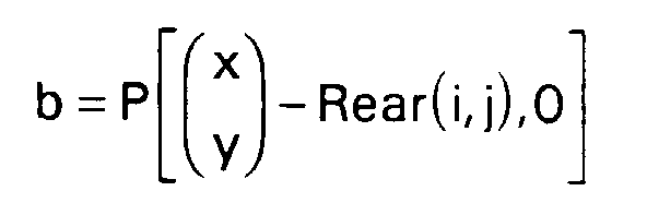
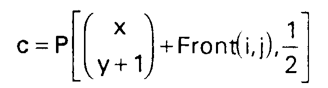

Pour y impair, on pose de même:
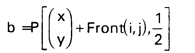


Ce filtrage est illustré par la figure 13.This filtering is illustrated in Figure 13.
P2(x,y) est la valeur du pixel interpolé et correspond à la valeur médiane parmi trois valeurs: les résultats de deux filtres linéaires et d'un filtre médian à partir des valeurs des pixels a, b et c.P 2 (x, y) is the value of the interpolated pixel and corresponds to the median value among three values: the results of two linear filters and a median filter from the values of pixels a, b and c.
Les deux filtres linéaires réalisent une interpolation temporelle avec des coefficients de pondération correspondant aux positions relatives du pixel à interpoler par rapport aux pixels a, b, c. Il faut noter que ce sont deux filtres temporels purs, c'est à dire n'utilisant qu'un seul pixel dans chacune des trames d'entrée. Ceci permet d'éviter une perte de résolution verticale.The two linear filters perform a temporal interpolation with weighting coefficients corresponding to the relative positions of the pixel to be interpolated with respect to the pixels a, b, c. Note that these are two pure time filters, i.e. using only one single pixel in each of the input frames. This avoids a loss of vertical resolution.
Le filtre médian permet également de conserver à la trame générée une bonne résolution spatiale. Mais il permet aussi de garder une certaine homogénéité entre les différents mécanismes d'interpolation des trois trames.The median filter also allows the generated frame to maintain good spatial resolution. But it also makes it possible to keep a certain homogeneity between the different interpolation mechanisms of the three frames.
Si le vecteur de mouvement lié à un sous-bloc est nul ou si la confiance accordée à un vecteur est bonne (erreur faible), l'interpolation sera, comme dans le cas de la trame 1, de type interpolation temporelle pure: on entrelace les lignes des trames 1 et 2/3 :If the motion vector linked to a sub-block is zero or if the confidence given to a vector is good (low error), the interpolation will be, as in the case of
Pour y pair:![]()
![]()
Pour y impair:![]()
![]()
On calcule d'autre part une seconde valeur possible pour c pixel, appelée valeur de repli. Cette valeur, notée Fallback2(x,y) correspond à un filtrage linéaire coupant très sévèrement les haute fréquences spatiales sur les deux trames concernées :
On définit également la confiance portée à un vecteur de mouvement comme :![]()
![]()
La valeur P2(x,y) du pixel interpolé sera alors :
La valeur P2(x,y) est égale à la valeur du pixel compensé en mouvement mais encadrée de manière à ne pas pouvoir s'écarter de la valeur du pixel de repli d'une valeur supérieure à la confiance divisée par un facteur correctif.The value P 2 (x, y) is equal to the value of the pixel compensated in motion but framed so as not to be able to deviate from the value of the fallback pixel by a value greater than the confidence divided by a corrective factor .
Les mécanismes sont très semblables à ceux employés pour la trame 2. La trame 3 est interpolée à partir des trames 2/3 et 4 (c'est à dire la trame 1 du cycle suivant) et des vecteurs des sous-blocs SB 3(i,j). Seuls les coefficients d'interpolation et les aspects de parité des lignes vont changer.The mechanisms are very similar to those used for
On calculera donc les vecteurs :
Pour y impair, soient


Pour y pair, on pose de même:


La figure 14 illustre ce filtrage.Figure 14 illustrates this filtering.
Si la confiance est très bonne et le vecteur nul, on optera encore pour une interpolation temporelle pure :
y pair:
P3(x,y)=P(x,y,1)
y impair:![]()
y pair:
P 3 (x, y) = P (x, y, 1)
y odd: ![]()
On calculera ensuite le pixel de repli,
![]()
![]()
Enfin, on établira la valeur du pixel affiché en interdisant à ce pixel de trop s'écarter de la valeur du pixel de repli si la confiance est mauvaise :
On voit qu'ici, la continuité de l'interpolation est bien assurée avec la trame précédente puisque l'algorithme est calqué sur l'interpolation de la trame 2. Cependant, les vecteurs de sous-blocs ont un biais temporel -dû au fait qu'ils ont été calculés à partir des blocs principaux déterminés pour la trame de sortie précédente- qui rend la définition de cette trame plus mauvaise que celle de la trame précédente, notamment dans le cas de mouvements rapidement évolutifs.We see that here, the continuity of the interpolation is well ensured with the previous frame since the algorithm is modeled on the interpolation of
L'interpolation de la chrominance est sujette à des contraintes beaucoup moins sévères que celle de la luminance; en effet, la définition de l'oeil est beaucoup plus faible. D'ailleurs, la norme utilisée pour la transmission sur le réseau hertzien, dite format 4:1:1, inclut un sous-échantillonnage aboutissant à transmettre une information de chrominance pour quatre informations de luminance, avec une répétition de l'information de chrominance identique à elle-même sur deux lignes. Les tolérances sur les filtres utilisés sont donc beaucoup plus grandes. De ce fait, nous nous contenterons de filtres simplifiés.The interpolation of chrominance is subject to much less severe constraints than that of luminance; indeed, the definition of the eye is much weaker. Moreover, the standard used for transmission on the radio network, known as 4: 1: 1 format, includes a sub-sampling resulting in transmitting chrominance information for four luminance information, with a repetition of the chrominance information identical to itself on two lines. The tolerances on the filters used are therefore much greater. Therefore, we will be content with simplified filters.
Les algorithmes d'interpolation de la chrominance sont donc directement extrapolés de ceux d'interpolation de la luminance, en considérant des trames contenant deux fois moins de pixels horizontalement, et en divisant donc par deux la composante horizontale des vecteurs de mouvement.The chrominance interpolation algorithms are therefore directly extrapolated from those of luminance interpolation, by considering frames containing half as many pixels horizontally, and therefore dividing the horizontal component of the motion vectors by two.
Pour la trame 1, le filtre à 7 pixels d'entrées utilisé en luminance est limité à 3 pixels d'entrée :For
Soient
vx = ![]()
vy =(0 1)·MB(i,j)
Pour y pair:
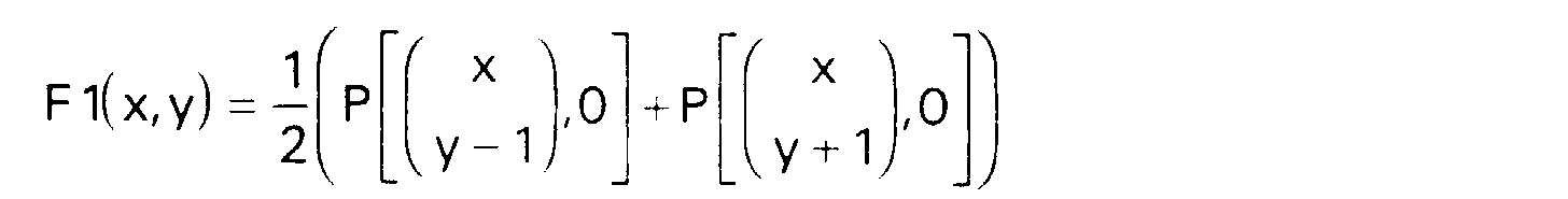


P1(x,y)=med3(F1(x,y);F2(x,y);F3(x,y))Are
v x = ![]()
v y = (0 1) MB (i, j)
To pair there:
P 1 (x, y) = med3 (F1 (x, y); F2 (x, y); F3 (x, y))
Pour les trames 2 et 3, les filtres médians temporels de la luminance sont conservés, mais on supprime le filtre de repli. Dans le filtre de réduction de bruit temporelle, le filtre horizontal est supprimé, car il filtrerait trop bas les fréquences spatiales.For
Le cas du mode film est celui des séquences vidéo qui sont générées, non pas au format 625/50/2, mais en 625/25/1. Ces séquences sont donc dans un format progressif à l'entrée, ce qui veut dire que chaque image d'entrée contient 2 trames correspondant au même instant.The case of film mode is that of video sequences which are generated, not in 625/50/2 format, but in 625/25/1. These sequences are therefore in a progressive format at the input, which means that each input image contains 2 frames corresponding to the same instant.
De là vient tout le problème: en effet si on applique à de telles séquences l'algorithme décrit ci-dessus, sans aucune modification, l'estimation de mouvement sera complètement inhibée, puisque le calcul des blocs principaux se fera entre les deux trames de la même image, et que toutes les estimations successives qui découlent de ceux-ci ne généreront que des vecteurs nuls. Si donc aucun mouvement n'est détecté, aucune interpolation temporelle ou compensation en mouvement ne pourra être faite. Ceci est très gênant, car à l'affichage de telles séquences, on ne pourra que répéter 3 fois à l'écran chaque image d'entrée. D'où un effet de saccade particulièrement désagréable dans toute séquence comportant du mouvement.From there comes all the problem: indeed if one applies to such sequences the algorithm described above, without any modification, the estimation of movement will be completely inhibited, since the calculation of the main blocks will be done between the two frames of the same image, and that all successive estimates that follow from them will only generate null vectors. If therefore no movement is detected, no time interpolation or compensation for movement can be made. This is very annoying, because when displaying such sequences, it will only be possible to repeat 3 times on the screen each input image. Hence a particularly unpleasant saccade effect in any sequence involving movement.
Une solution simple et peu coûteuse permettant de réduire considérablement cet effet de saccade est la suivante: on va modifier la phase du traitement des informations de façon à ce que le mouvement entre 2 images différentes soit détecté et estimé, et que donc une interpolation temporelle soit possible.A simple and inexpensive solution making it possible to considerably reduce this jerky effect is as follows: we are going to modify the phase of information processing so that the movement between 2 different images is detected and estimated, and therefore a temporal interpolation is possible.
Par conséquent, l'estimation de mouvement principale (la phase des blocs principaux) devra se faire entre une trame 1 paire et une trame 2/3 impaire et non plus entre une trame 1 impaire et une trame 2/3 paire. Les chronogrammes donnés figure 15 illustrent ce mode de fonctionnement particulier.Consequently, the main motion estimation (the phase of the main blocks) will have to be done between a 1 even frame and an odd 2/3 frame and no longer between a 1 odd frame and a 2/3 even frame. The timing diagrams given in Figure 15 illustrate this particular mode of operation.
Tout le traitement sera ainsi décalé d'une trame 50hz. Ce qui veut dire qu'en sortie les lignes à interpoler auront la parité opposée à celle qu'elles ont lors du traitement normal. Mais les filtres et l'estimateur de mouvement fonctionneront de façon strictement identique. Ainsi on générera successivement :
une trame 1 progressive en utilisant le champ de vecteurs de blocs principaux, en conservant les lignes d'entrée et en interpolant les autres avec le filtre médian spatio-temporel à 7 points décrit précédemment,une trame 2 progressive en utilisant le champ de vecteurs de sous-blocs estimé avec les trames 1et 2/3 d'entrée. On utilisera ici aussi le filtre médian temporel à 3 points décrit précédemment. Par contre au lieu d'appliquer les coefficients de pondération 2/3et 1/3 ordinaires, on utilisera lescoefficients 1/2et 1/2; ce qui veut dire que la trame 2 que l'on génère ainsi est située à égale distance entre les trames d'entrées 1et 2/3. Cette simple modification des coefficients constitue à elle seule une importante réduction de saccade, bien appréciable et sensible sur toutes les images qui ont été traitées. Voir figure 16 le schéma explicatif de cette réduction de saccade.- et enfin une trame 3 progressive utilisant normalement le champ de vecteur des sous-blocs corrigé par les blocs intermédiaires. En fait, ici, puisque les trames 2/3
et 4 sont issues de la même image, il n'y a pas de mouvement entre ces deux trames. Il suffit donc de forcer les vecteur à zéro ainsi que la confiance: de cette façon le filtre décrit précédemment entrelacera purement et simplement les 2 trames d'entrée pour régénérer une image progressive parfaite.
- a
progressive frame 1 by using the main block vector field, by preserving the input lines and by interpolating the others with the 7-point space-time median filter described above, - a
progressive frame 2 using the sub-block vector field estimated with the input frames 1 and 2/3. Here we will also use the 3-point time median filter described above. On the other hand, instead of applying the ordinary 2/3 and 1/3 weighting coefficients, we will use thecoefficients 1/2 and 1/2; which means that theframe 2 which is thus generated is located at equal distance between the input frames 1 and 2/3. This simple modification of the coefficients in itself constitutes a significant reduction in saccade, very appreciable and sensitive on all the images which have been processed. See figure 16 the explanatory diagram of this reduction of saccade. - and finally a
progressive frame 3 normally using the vector field of the sub-blocks corrected by the intermediate blocks. In fact, here, since theframes 2/3 and 4 come from the same image, there is no movement between these two frames. It is therefore enough to force the vectors to zero as well as the confidence: in this way the filter described above will purely and simply interleave the 2 input frames to regenerate a perfect progressive image.
En conclusion, le mode film pourra être traité sans modification des filtres et mécanismes d'estimation de mouvement: il suffira de contrôler, lorsqu'on aura détecté la présence du mode film, la phase du traitement, les coefficients d'interpolation du filtre des trames 2 ainsi que les vecteurs et confiances des trames 3. La réduction de saccade ainsi obtenue sera donc peu coûteuse à implémenter.In conclusion, the film mode can be processed without modification of the filters and motion estimation mechanisms: it will suffice to check, when the presence of the film mode has been detected, the phase of the processing, the interpolation coefficients of the filter of the
Claims (10)


Applications Claiming Priority (2)
| Application Number | Priority Date | Filing Date | Title |
|---|---|---|---|
| FR9515403A FR2742902B1 (en) | 1995-12-22 | 1995-12-22 | MOVEMENT ESTIMATION METHOD |
| FR9515403 | 1995-12-22 |
Publications (1)
| Publication Number | Publication Date |
|---|---|
| EP0780795A1 true EP0780795A1 (en) | 1997-06-25 |
Family
ID=9485890
Family Applications (1)
| Application Number | Title | Priority Date | Filing Date |
|---|---|---|---|
| EP96402778A Ceased EP0780795A1 (en) | 1995-12-22 | 1996-12-18 | Motion estimation process |
Country Status (4)
| Country | Link |
|---|---|
| EP (1) | EP0780795A1 (en) |
| JP (1) | JPH09233435A (en) |
| CN (1) | CN1168062A (en) |
| FR (1) | FR2742902B1 (en) |
Cited By (1)
| Publication number | Priority date | Publication date | Assignee | Title |
|---|---|---|---|---|
| EP0936575A1 (en) * | 1998-02-17 | 1999-08-18 | Koninklijke Philips Electronics N.V. | Image processing method for motion estimation in a sequence of images, method of filtering noise, and medical imaging apparatus utilising these methods |
Families Citing this family (7)
| Publication number | Priority date | Publication date | Assignee | Title |
|---|---|---|---|---|
| JP4553332B2 (en) * | 2000-04-12 | 2010-09-29 | キヤノン株式会社 | Area dividing method and apparatus, and storage medium |
| US8649437B2 (en) | 2007-12-20 | 2014-02-11 | Qualcomm Incorporated | Image interpolation with halo reduction |
| WO2009085232A1 (en) * | 2007-12-20 | 2009-07-09 | Integrated Device Technology, Inc. | Estimation of true motion vectors using an adaptive search range |
| JP4374048B2 (en) * | 2007-12-26 | 2009-12-02 | 株式会社東芝 | Interpolated frame generating apparatus, interpolated frame generating method, and broadcast receiving apparatus |
| US8537283B2 (en) | 2010-04-15 | 2013-09-17 | Qualcomm Incorporated | High definition frame rate conversion |
| KR101394468B1 (en) * | 2013-11-12 | 2014-05-14 | 주식회사 아나패스 | Calculation method for discontinuity of a block and fallback performing method using the same |
| US11381834B2 (en) | 2018-04-02 | 2022-07-05 | Hfi Innovation Inc. | Video processing methods and apparatuses for sub-block motion compensation in video coding systems |
Citations (1)
| Publication number | Priority date | Publication date | Assignee | Title |
|---|---|---|---|---|
| EP0648052A1 (en) | 1993-09-08 | 1995-04-12 | THOMSON multimedia | Method and apparatus for motion estimation using block matching |
-
1995
- 1995-12-22 FR FR9515403A patent/FR2742902B1/en not_active Expired - Fee Related
-
1996
- 1996-12-18 EP EP96402778A patent/EP0780795A1/en not_active Ceased
- 1996-12-20 JP JP8342172A patent/JPH09233435A/en active Pending
- 1996-12-22 CN CN96123943A patent/CN1168062A/en active Pending
Patent Citations (1)
| Publication number | Priority date | Publication date | Assignee | Title |
|---|---|---|---|---|
| EP0648052A1 (en) | 1993-09-08 | 1995-04-12 | THOMSON multimedia | Method and apparatus for motion estimation using block matching |
Non-Patent Citations (1)
| Title |
|---|
| SOHAIL ZAFAR ET AL.: "Predictive Block-matching motion estimation schemes for Video compression (Digest)", PROCEEDINGS OF THE INTERNATIONAL CONFERENCE ON CONSUMER ELECTRONICS, JUNE 5-7 ,1991 ,ROSEMONT (US); IEEE PRESS ,NEW YORK (US), 1991, pages 300 - 301, XP000289044 * |
Cited By (2)
| Publication number | Priority date | Publication date | Assignee | Title |
|---|---|---|---|---|
| EP0936575A1 (en) * | 1998-02-17 | 1999-08-18 | Koninklijke Philips Electronics N.V. | Image processing method for motion estimation in a sequence of images, method of filtering noise, and medical imaging apparatus utilising these methods |
| US6154519A (en) * | 1998-02-17 | 2000-11-28 | U.S. Philips Corporation | Image processing method for motion estimation in a sequence of images, noise filtering method and medical imaging apparatus utilizing such methods |
Also Published As
| Publication number | Publication date |
|---|---|
| CN1168062A (en) | 1997-12-17 |
| FR2742902B1 (en) | 1998-01-23 |
| FR2742902A1 (en) | 1997-06-27 |
| JPH09233435A (en) | 1997-09-05 |
Similar Documents
| Publication | Publication Date | Title |
|---|---|---|
| EP0781041B1 (en) | Progressive frames interpolation system | |
| EP0780794B1 (en) | Motion estimation correction process in images with a periodical structure | |
| EP0390660B1 (en) | Method and apparatus for the temporal interpolation of pictures, with corrected movement compensation | |
| EP0316231B1 (en) | Method and arrangement for processing interlace-scanned image signals | |
| EP1908297B1 (en) | Device for generating an interpolated frame | |
| FR2766946A1 (en) | PRETREATMENT METHOD AND DEVICE FOR MOTION ESTIMATION | |
| WO2010007285A1 (en) | Method and device for filling in the zones of occultation of a map of depth or of disparities estimated on the basis of at least two images | |
| WO1994016522A1 (en) | Method for de-interlacing fields of a sequence of moving images | |
| FR2958824A1 (en) | PROCESS FOR PROCESSING STEREOSCOPIC IMAGES AND CORRESPONDING DEVICE | |
| FR2594281A1 (en) | APPARATUS FOR ESTIMATING NOISE IN SIGNALS HAVING REDUNDANT INTERVALS | |
| KR101125977B1 (en) | Image processing apparatus and method, recording medium | |
| WO2015132255A1 (en) | Optimised video denoising for heterogeneous multisensor system | |
| FR2599204A1 (en) | Video signal processor with progressive scan | |
| EP0780795A1 (en) | Motion estimation process | |
| EP0337565B1 (en) | Device for coding signals representative of a sequence of pictures and system for transmission of high definition television pictures including such a device | |
| EP1790169A1 (en) | Method for estimating motion using deformable meshes | |
| EP3594895A1 (en) | Space-time video content noise reducer based on confidence indices | |
| FR2968108A1 (en) | Method for processing video image to display stereoscopic image on target screen of e.g. TV, involves calculating target disparity information associated to part of image according to disparity budget and original disparity information | |
| Sapkal et al. | Image inpainting by Kriging interpolation technique for mask removal | |
| FR2736741A1 (en) | METHOD FOR PROCESSING A SOURCE SEQUENCE OF BLINKING DIGITAL IMAGES | |
| FR2934453A1 (en) | ERROR MASKING METHOD AND DEVICE | |
| FR2536941A1 (en) | PROCESS FOR THE COMBAL FILTERING FROM ONE IMAGE TO THE OTHER OF A TELEVISION COMPOSITE SIGNAL AND A COMB FILTER FOR USE THEREIN | |
| EP2761876A1 (en) | Method and device for filtering a disparity map | |
| Patanavijit | A nonlinear myriad filter for a recursive video enhancement using a robust srr based on stochastic regularization | |
| CA2376684C (en) | Optimal video decoder based on mpeg-type standards |
Legal Events
| Date | Code | Title | Description |
|---|---|---|---|
| PUAI | Public reference made under article 153(3) epc to a published international application that has entered the european phase |
Free format text: ORIGINAL CODE: 0009012 |
|
| AK | Designated contracting states |
Kind code of ref document: A1 Designated state(s): DE FR GB IT |
|
| 17P | Request for examination filed |
Effective date: 19971208 |
|
| RAP1 | Party data changed (applicant data changed or rights of an application transferred) |
Owner name: THOMSON MULTIMEDIA |
|
| 17Q | First examination report despatched |
Effective date: 20001102 |
|
| GRAG | Despatch of communication of intention to grant |
Free format text: ORIGINAL CODE: EPIDOS AGRA |
|
| STAA | Information on the status of an ep patent application or granted ep patent |
Free format text: STATUS: THE APPLICATION HAS BEEN REFUSED |
|
| 18R | Application refused |
Effective date: 20020927 |