EP0780246B1 - Radial tyre - Google Patents
Radial tyre Download PDFInfo
- Publication number
- EP0780246B1 EP0780246B1 EP96120690A EP96120690A EP0780246B1 EP 0780246 B1 EP0780246 B1 EP 0780246B1 EP 96120690 A EP96120690 A EP 96120690A EP 96120690 A EP96120690 A EP 96120690A EP 0780246 B1 EP0780246 B1 EP 0780246B1
- Authority
- EP
- European Patent Office
- Prior art keywords
- notches
- iii
- tread strip
- grooves
- width
- Prior art date
- Legal status (The legal status is an assumption and is not a legal conclusion. Google has not performed a legal analysis and makes no representation as to the accuracy of the status listed.)
- Expired - Lifetime
Links
- 239000011295 pitch Substances 0.000 claims 1
- 230000005855 radiation Effects 0.000 description 17
- 230000009467 reduction Effects 0.000 description 8
- 230000008901 benefit Effects 0.000 description 6
- 238000013461 design Methods 0.000 description 6
- 238000001228 spectrum Methods 0.000 description 6
- 230000000694 effects Effects 0.000 description 5
- 238000005299 abrasion Methods 0.000 description 4
- 239000006096 absorbing agent Substances 0.000 description 4
- 238000005096 rolling process Methods 0.000 description 4
- 239000011324 bead Substances 0.000 description 3
- 230000002349 favourable effect Effects 0.000 description 3
- 229910000831 Steel Inorganic materials 0.000 description 2
- 238000011161 development Methods 0.000 description 2
- 230000018109 developmental process Effects 0.000 description 2
- 239000000835 fiber Substances 0.000 description 2
- 238000005259 measurement Methods 0.000 description 2
- 239000010959 steel Substances 0.000 description 2
- 239000004677 Nylon Substances 0.000 description 1
- 238000010521 absorption reaction Methods 0.000 description 1
- 230000009471 action Effects 0.000 description 1
- 230000003321 amplification Effects 0.000 description 1
- 239000004760 aramid Substances 0.000 description 1
- 229920003235 aromatic polyamide Polymers 0.000 description 1
- 230000009286 beneficial effect Effects 0.000 description 1
- 230000008033 biological extinction Effects 0.000 description 1
- 230000015572 biosynthetic process Effects 0.000 description 1
- 230000008859 change Effects 0.000 description 1
- 238000010276 construction Methods 0.000 description 1
- 230000008878 coupling Effects 0.000 description 1
- 238000010168 coupling process Methods 0.000 description 1
- 238000005859 coupling reaction Methods 0.000 description 1
- 230000001419 dependent effect Effects 0.000 description 1
- 230000001066 destructive effect Effects 0.000 description 1
- 238000010586 diagram Methods 0.000 description 1
- 238000005538 encapsulation Methods 0.000 description 1
- 238000009434 installation Methods 0.000 description 1
- 238000000034 method Methods 0.000 description 1
- 238000003199 nucleic acid amplification method Methods 0.000 description 1
- 229920001778 nylon Polymers 0.000 description 1
- 229920000728 polyester Polymers 0.000 description 1
- 239000011148 porous material Substances 0.000 description 1
- 230000002787 reinforcement Effects 0.000 description 1
- 239000004575 stone Substances 0.000 description 1
- 239000000758 substrate Substances 0.000 description 1
- 230000003319 supportive effect Effects 0.000 description 1
- 238000012360 testing method Methods 0.000 description 1
- 230000007704 transition Effects 0.000 description 1
Images


Classifications
-
- B—PERFORMING OPERATIONS; TRANSPORTING
- B60—VEHICLES IN GENERAL
- B60C—VEHICLE TYRES; TYRE INFLATION; TYRE CHANGING; CONNECTING VALVES TO INFLATABLE ELASTIC BODIES IN GENERAL; DEVICES OR ARRANGEMENTS RELATED TO TYRES
- B60C11/00—Tyre tread bands; Tread patterns; Anti-skid inserts
- B60C11/03—Tread patterns
- B60C11/0318—Tread patterns irregular patterns with particular pitch sequence
-
- B—PERFORMING OPERATIONS; TRANSPORTING
- B60—VEHICLES IN GENERAL
- B60C—VEHICLE TYRES; TYRE INFLATION; TYRE CHANGING; CONNECTING VALVES TO INFLATABLE ELASTIC BODIES IN GENERAL; DEVICES OR ARRANGEMENTS RELATED TO TYRES
- B60C11/00—Tyre tread bands; Tread patterns; Anti-skid inserts
- B60C11/03—Tread patterns
- B60C11/0302—Tread patterns directional pattern, i.e. with main rolling direction
-
- B—PERFORMING OPERATIONS; TRANSPORTING
- B60—VEHICLES IN GENERAL
- B60C—VEHICLE TYRES; TYRE INFLATION; TYRE CHANGING; CONNECTING VALVES TO INFLATABLE ELASTIC BODIES IN GENERAL; DEVICES OR ARRANGEMENTS RELATED TO TYRES
- B60C11/00—Tyre tread bands; Tread patterns; Anti-skid inserts
- B60C11/03—Tread patterns
- B60C11/11—Tread patterns in which the raised area of the pattern consists only of isolated elements, e.g. blocks
-
- B—PERFORMING OPERATIONS; TRANSPORTING
- B60—VEHICLES IN GENERAL
- B60C—VEHICLE TYRES; TYRE INFLATION; TYRE CHANGING; CONNECTING VALVES TO INFLATABLE ELASTIC BODIES IN GENERAL; DEVICES OR ARRANGEMENTS RELATED TO TYRES
- B60C11/00—Tyre tread bands; Tread patterns; Anti-skid inserts
- B60C11/03—Tread patterns
- B60C11/13—Tread patterns characterised by the groove cross-section, e.g. for buttressing or preventing stone-trapping
- B60C11/1376—Three dimensional block surfaces departing from the enveloping tread contour
- B60C11/1384—Three dimensional block surfaces departing from the enveloping tread contour with chamfered block corners
-
- B—PERFORMING OPERATIONS; TRANSPORTING
- B60—VEHICLES IN GENERAL
- B60C—VEHICLE TYRES; TYRE INFLATION; TYRE CHANGING; CONNECTING VALVES TO INFLATABLE ELASTIC BODIES IN GENERAL; DEVICES OR ARRANGEMENTS RELATED TO TYRES
- B60C11/00—Tyre tread bands; Tread patterns; Anti-skid inserts
- B60C11/03—Tread patterns
- B60C2011/0337—Tread patterns characterised by particular design features of the pattern
- B60C2011/0386—Continuous ribs
- B60C2011/0388—Continuous ribs provided at the equatorial plane
Definitions
- the present invention relates to a radial tire, in particular for the Drive wheels of trucks or buses with a tread pattern according to the preamble of claim 1
- Radial tires particularly suitable for the drive wheels of trucks are generally have a tread pattern with a pronounced Log structure on.
- One of these well-known truck tires for example in AT-B-394 337 is described has a tread pattern which can be found in essentially from a central one running along the tire equator line Row of blocks, two middle and one shoulder row of blocks composed by circumferential grooves in the circumferential direction are separated from each other. The blocks in the individual rows of blocks are through transverse grooves inclined relative to the circumferential direction from one another Cut.
- Another typical traction profile from the prior art known truck tire shows Fig. 1, where the scaled-down pint print this Tire is shown.
- This profile has four rows of blocks, with the blocks through the formation of wide grooves 20 running obliquely over the tread as well through narrow grooves 21 which run obliquely in the same direction and in opposite directions to these running narrow grooves 22 have an approximately V-shaped basic shape.
- a tire with a tread pattern of the type mentioned is from GB-A-738 143 known.
- the main thing here is the grip properties of a To improve profile in the lateral direction and in the circumferential direction, including the Noise development and abrasion behavior should be taken into account.
- At a of the illustrated and described embodiments are in the central region of the Tread two rows of blocks, their adjacent circumferential blocks are separated from each other by grooves running in the transverse direction, and in each side area a further row of blocks, whose blocks through diagonally running grooves are separated from each other.
- the diagonally running grooves form an angle of 45 with the circumferential direction of the tire up to 70 °.
- the The applicant is also a device to be preferably attached to the wheel arch disclosed, which has a system of sound absorbers that respond to certain noise components in tire / road noise, the frequencies of which are proportional to Change wheel speed, is tuned and can be actively adjusted.
- the present invention begins, the task of which is to Tires, especially on the tread pattern, to take measures on the one hand the effectiveness of passive or active sound absorbing devices on Motor vehicle, especially on the wheel arch, help improve and on the other hand also the tire / road noise, both in terms of the emitted Frequency spectrum as well as in terms of sound pressure level, cheap influence.
- the energy distribution in the excited resonances is depending on the driving speed and the number of blocks, road-dependent parameters, such as roughness and pore volume the road surface, and specific eigenmodes of the tire structure. Since both radiate the open ends of such a channel coherently, a spatial one is formed Interference pattern from with radiation directions with constructive interference what a sound amplification, and destructive interference, which is a sound cancellation corresponds. In a tread pattern designed according to the invention forms the interference pattern is approximately such that sound radiation primarily in and against the direction of travel, but to the side of the tire is greatly reduced Sound radiation. Due to the longitudinal grooves, the profile according to the invention has good Abrasion and aquaplaning properties.
- the two are Tread areas through a circumferential groove in the circumferential direction separated from each other, into which the diagonal grooves of both Open sides, this circumferential groove preferably along the Circumferential center line of the profile runs.
- the arrangement of a circumferential groove in The central area of the tread supports the physical described above Effect and is therefore overall favorable for a reduction in sound radiation in the lateral direction and bundling the sound radiation in or against the Direction of travel.
- they are in one Tread area grooves running in opposite directions to those in the other Tread area arranged trending.
- This variant is thus with a directional and swept profile opposite slope of the grooves.
- the desired and achievable Sound radiation characteristics can therefore favorably with the advantages a directional profile, such as an improved one Aquaplaning behavior.
- they have in the two Tread areas running grooves matching course or the same Pitch.
- Another advantageous embodiment provides that the in the one tread area running grooves from those in the second Tread area extending are offset in the circumferential direction. This Measure has a certain supportive effect on those with the object invention achievable sound radiation characteristics.
- the course or the arrangement of the longitudinal grooves can vary from the exact one Circumferential direction, which for certain profile properties, for example, the traction and braking behavior is an advantage.
- the desired sound radiation characteristics as much as possible to ensure it is favorable if the longitudinal grooves have a course that around deviates up to 10 °, in particular up to 5 °, from the circumferential direction.
- FIG. 1 is a scaled-down pint print Tread pattern of a tire from the prior art
- Fig. 1a, 2a and 5a Images of sound field measurements
- the tread patterns designed according to the invention are particularly for Drive axle tires provided for trucks.
- the other structure of the truck tires can done in a conventional manner and includes in particular in addition to the Tread a pair of bead areas with bead cores, a pair of Sidewalls, a radial carcass, the free ends of which around the bead cores and a multi-layer belt.
- a reinforcement cord for the or multi-ply carcass is generally considered steel cord, also organic fiber, such as nylon or polyester or a aromatic polyamide.
- the belt comprises three to four layers, which in each layer parallel cords made of steel or also organic Have fiber cord with respect to the tire equator at certain angles run.
- the present invention is basically concerned with tread patterns for To design tires so that on the one hand the tire / road noise both regarding sound pressure level as well as distribution of the occurring frequencies is influenced favorably overall and on the other hand one in and against the the direction of travel (rolling direction) of the tire is largely directed Sound radiation and a reduction in sound radiation in the side Direction is supported.
- the tire according to the invention should above all Motor vehicles, especially on trucks or buses, can be used on the Wheel housings are provided with suitable devices for sound absorption.
- the Measures taken to achieve this goal are now based on the basic design variants explained in more detail.
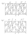
- the embodiment according to FIG. 2 is an arrowed, Directional tread pattern. It is along the Tire circumferential center line A-A arranged a wide circumferential groove 2 which, like shown, can be designed as a straight circumferential groove. In every Half of the tread are broad, diagonal grooves 10 as main grooves arranged, in this embodiment, except for the area of their Openings in the circumferential groove 2 or their transition areas on the Tread edges where the grooves 10 each in the transverse direction of the tread pattern have curved end portions, at least substantially straight run.
- the grooves 10 running in one tread half are through the arrowed arrangement to the grooves running in the other half of the tread 10 mutually inclined and close an angle with the circumferential center line A-A ⁇ , which is chosen between 35 +/- 20 °, in particular between 35 +/- 10 °.
- the grooves 10 are in one tread half arranged offset in relation to the grooves 10 in the second tread half. This offset can be up to half the mutual distance between adjacent grooves 10 be performed.
- Such a tire is arranged on the vehicle such that the tread end regions of the grooves 10 first into the Enter the contact surface with the substrate.
- the grooves 10 are in each tread half by relatively narrow, at least substantially longitudinal grooves 3 running in the circumferential direction connected to each other, creating a block structure.
- the average width of the narrow longitudinal grooves 3 is between 10 and 60%, in particular 20 to 40%, of Width of the grooves 10 selected.
- the course of the longitudinal grooves 3 can be +/- 10 °, in particular +/- 5 °, deviate from the circumferential direction.
- the wide grooves 10 are acoustically coupled by the narrow longitudinal grooves 3. It is therefore advantageous to close the longitudinal grooves 3 in the transverse direction of the tire move so that there is no aligned arrangement of longitudinal grooves 3.
- the offset of the longitudinal grooves 3 creates a block structure in which the number of Blocks 4 between adjacent grooves 10 differs from each other, so that illustrated embodiment in each tread half between adjacent grooves 10 alternately three blocks 4 and four blocks 4 available.
- This profile design has 3 good abrasion and through the longitudinal grooves Aquaplaning properties. At the same time it is ensured that an in and sound radiation directed against the direction of travel and a reduction of the lateral sound radiation is achieved.
- the described offset of the longitudinal grooves 3 additionally causes that during the When the tire rolls off, the energy of the blocks hitting the ground over time is distributed, which has an overall favorable effect on the sound pressure level.
- the offset shown in the one Half of tread grooves 10 against those in the other Half of tread grooves 10 are dispensed with, so that the grooves 10 in open the circumferential groove 2 without mutual offset.
- the tread pattern is designed such that, when viewed in the transverse direction of the profile, the number of grooves 10, depending on the tire dimension, is between 6 and 12, in particular between 8 and 10.
- the width of the grooves 10 is kept at least substantially constant, all grooves 10 in particular having the same width.
- the cross section of the grooves 10 can be U-shaped, V-shaped or the like, symmetrical or asymmetrical.
- known measures for stone rejection can be taken, such as raising the base of the groove.
- the circumferential groove 2 can deviate from the embodiment shown also designed wave-shaped or zigzag become.
- Fig. 3 shows a variant of the embodiment shown in Fig. 2, in which in addition to a central circumferential groove 2 ', grooves 10' in each tread half are arranged, each corresponding over a large part of their lengths Own slope. Accordingly, this profile variant is not directional.
- the mouth areas of the grooves 10 ', both in the area of the circumferential groove 2 'and the tread edges are in turn designed such that the Grooves 10 'in each case via a rounded kink in the middle into the circumferential groove 2' open out or run out into the shoulder areas at the edge of the tread.
- the further configuration of the profile with longitudinal grooves 3 ' corresponds to that according to FIG. 2, as well as the angulation of the grooves 10 'and their other configuration.
- Fig. 4 differs from that 3 only in that the grooves 10 "in one tread half opposite the grooves 10 "in the other tread half in the circumferential direction are offset.
- the longitudinal grooves 3 are provided analogously.
- 5 to 7 show further exemplary embodiments which show further variants of the in 2 to 4 are examples shown.
- FIG. 5 corresponds to that of FIG. 2 except for the design of the central region.
- there are grooves 10 III longitudinal grooves 3 III in each tread half, each with the appropriate angulation and offset, arranged.
- No circumferential groove is now provided in the central area of the tread so that the grooves 10 III end there as pocket grooves, preferably and as shown to form a rounded kink at the respective ends.
- the central tread area is thus more closed than in the embodiment variants according to FIGS. 2 to 4, which results in a certain reduction in the effectiveness of the physical principle of action on which these embodiments are based.
- the closed grooves 10 III emit a little more noise, mutual extinction is mainly possible in the inlet and outlet.
- the advantage of this tread pattern lies primarily in the fact that in the central region of the tread a rib structure is created by the runout of the grooves 10 III there, which significantly improves the abrasion behavior.
- FIG. 6 shows a variant essentially corresponding to FIG. 4, which accordingly has grooves 10 IV that are the same in both tread halves, the central region of the tread profile is designed analogously to the variant according to FIG. 4, with no offset of the grooves 10 running in one tread half IV compared to those of the grooves 10 IV running in the second tread half.
- FIG. 7 A variant with an offset of the grooves 10 V in one tread half compared to the grooves 10 V in the second tread half is shown in FIG. 7.
- the other configuration of the variants shown in FIGS. 6 and 7 basically corresponds to that according to FIG. 5.
- 1a, 1b, 2a, 2b and 5a, 5b illustrate with the aid of illustrations of measured sound fields and determined frequency spectra the effectiveness of the subject invention.
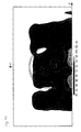
- 1a, 2a and 5a show in gray-coded, three-dimensional representations of the tire in the lateral direction, through a Plane parallel to the tire running direction, perpendicular to the ground and in approx. 20 cm sound intensity radiated from the side of the tire or Sound power.
- the measurements were carried out on a drum test bench at a Speed of 70 km / h.
- the Line markings on the rectangle enclosing the representations show this Measuring grid. At each crossing point of these markings vertical and horizontal line, the sound intensity was perpendicular to Drawing level determined and shown as a gray value.
- the scale at the foot of the The diagrams show the sound power assigned to each gray level in dB.
- Fig. 1a now shows the extent and type of the measured from the side Sound field of a truck tire with a state of the art executed traction profile.
- the tire measured had the one shown in FIG. 1 Profile design with a distinctive block structure.
- the sound field of this known tire is clearly spread with the intensity distribution characterized by the different shades of gray.
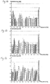
- the frequency spectrum shown in Fig. 1 b shows pronounced peaks in certain frequency ranges and a high sound pressure level.
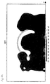
- Fig. 2a That measured with a tire whose profile was equipped according to FIG. 2 Sound field is shown in Fig. 2a.
- the sound radiation is in the lateral direction significantly reduced.
- the frequency spectrum (Fig. 2b) shows less pronounced Peaks and a significantly reduced sound power.
- the profile is through Circumferential centerline divided into two tread areas, which are the two Tread halves are. Deviating from this can be an outline of the profile also take place in tread areas that are not the two tread halves, by, for example, the circumferential groove offset from the circumferential center line is arranged. This results in asymmetrical profile configurations, which are also within the scope of the present invention.
Landscapes
- Engineering & Computer Science (AREA)
- Mechanical Engineering (AREA)
- Tires In General (AREA)
- Mechanical Operated Clutches (AREA)
- Yarns And Mechanical Finishing Of Yarns Or Ropes (AREA)
- Valve-Gear Or Valve Arrangements (AREA)
Abstract
Description
Die vorliegende Erfindung betrifft einen Radialreifen, insbesondere für die Antriebsräder von Lastkraftwagen oder Bussen, mit einem Laufstreifenprofil gemäß dem Oberbegriff des Anspruches 1The present invention relates to a radial tire, in particular for the Drive wheels of trucks or buses with a tread pattern according to the preamble of claim 1
Radialreifen, die insbesondere für die Antriebsräder von Lastkraftwagen geeignet
sind, weisen im allgemeinen ein Laufstreifenprofil mit einer ausgeprägten
Klotzstruktur auf. Einer dieser bekannten LKW-Reifen, der beispielsweise auch in
der AT-B-394 337 beschrieben ist, besitzt ein Laufstreifenprofil, welches sich im
wesentlichen aus einer zentralen, entlang der Reifenäquatorlinie verlaufenden
Klotzreihe, zwei mittleren und je einer schulterseitig verlaufenden Klotzreihe
zusammensetzt, die durch in Umfangsrichtung verlaufende Umfangsnuten
voneinander getrennt sind. Die Klötze in den einzelnen Klotzreihen sind durch
gegenüber der Umfangsrichtung geneigt verlaufenden Querrillen voneinander
getrennt. Ein weiteres typisches Traktionsprofil eines aus dem Stand der Technik
bekannten LKW-Reifens zeigt Fig. 1, wo der verkleinerte Latschabdruck dieses
Reifens dargestellt ist. Dieses Profil besitzt vier Klotzreihen, wobei die Klötze durch
die Ausbildung von schräg über die Lauffläche verlaufenden breiten Rillen 20 sowie
durch gleichsinnig schräg verlaufende schmale Rillen 21 und zu diesen gegensinnig
verlaufenden schmalen Rillen 22 eine etwa V-förmige Grundgestalt besitzen.Radial tires, particularly suitable for the drive wheels of trucks
are generally have a tread pattern with a pronounced
Log structure on. One of these well-known truck tires, for example in
AT-B-394 337 is described has a tread pattern which can be found in
essentially from a central one running along the tire equator line
Row of blocks, two middle and one shoulder row of blocks
composed by circumferential grooves in the circumferential direction
are separated from each other. The blocks in the individual rows of blocks are through
transverse grooves inclined relative to the circumferential direction from one another
Cut. Another typical traction profile from the prior art
known truck tire shows Fig. 1, where the scaled-down pint print this
Tire is shown. This profile has four rows of blocks, with the blocks through
the formation of
Ein Reifen mit einem Laufstreifenprofil der eingangs genannten Art ist aus der GB-A-738 143 bekannt. Hier geht es vor allem darum, die Griffeigenschaften eines Profils in seitlicher Richtung und in Umfangsrichtung zu verbessern, wobei auch die Geräuschentwicklung und das Abriebsverhalten beachtet werden sollen. Bei einer der dargestellten und beschriebenen Ausführungsformen sind im Mittelbereich des Laufstreifens zwei Klotzreihen, deren in Umfangsrichtung benachbarte Klötze jeweils durch in Querrichtung verlaufende Rillen voneinander getrennt sind, und in jedem seitlichen Bereich eine weitere Klotzreihe, deren Klötze durch diagonal verlaufende Rillen voneinander getrennt sind, angeordnet. Die diagonal verlaufenden Rillen schließen mit der Reifenumfangsrichtung einen Winkel von 45 bis 70° ein. A tire with a tread pattern of the type mentioned is from GB-A-738 143 known. The main thing here is the grip properties of a To improve profile in the lateral direction and in the circumferential direction, including the Noise development and abrasion behavior should be taken into account. At a of the illustrated and described embodiments are in the central region of the Tread two rows of blocks, their adjacent circumferential blocks are separated from each other by grooves running in the transverse direction, and in each side area a further row of blocks, whose blocks through diagonally running grooves are separated from each other. The diagonally running grooves form an angle of 45 with the circumferential direction of the tire up to 70 °.
Die in den letzten Jahren seitens der Kraftfahrzeughersteller verstärkt gesetzten Maßnahmen zur Verminderung der durch den Straßenverkehr verursachten Lärmbelästigung, wie etwa das Anbringen von schalldämmenden Motorkapselungen, hatte zur Folge, daß das Reifen/Fahrbahngeräusch immer mehr zur dominierenden Lärmquelle wurde. Dabei entwickeln LKW-Reifen aus konstruktionsbedingten Gründen ein als störender empfundenes Rollgeräusch als PKW-Reifen. Die am Reifen selbst zur Verminderung der Lärmbelästigung gesetzten Maßnahmen zielten bisher insbesondere darauf ab, das Reifen/Fahrbahngeräusch hinsichtlich einer Verteilung der auftretenden Frequenzen auf ein breiteres Frequenzband zu beeinflussen, was als angenehmer empfunden wird, als eine Schallabstrahlung mit vorherrschenden Frequenzen. Die diesbezüglich am Laufstreifenprofil eines Reifens gesetzten Maßnahmen erschöpften sich im wesentlichen in der Anwendung des Verfahrens der Pitchlängenvariation.The automotive manufacturers have increasingly set in recent years Measures to reduce road traffic Noise pollution, such as the installation of sound-absorbing Engine encapsulation, resulted in the tire / road noise becoming more and more became the dominant source of noise. Thereby develop truck tires construction-related reasons as a disturbing rolling noise as Car tires. The on the tire itself to reduce noise pollution The measures taken so far have been aimed in particular at: Tire / road noise regarding a distribution of the occurring Frequencies to affect a wider frequency band, which is more pleasant is perceived as a sound radiation with prevailing frequencies. The measures taken in this regard on the tread pattern of a tire exhausted essentially in the application of the method of Pitch length variation.
In jüngster Vergangenheit wurden ferner Überlegungen angestellt, in den Radkästen der Kraftfahrzeuge schallabsorbierende Vorrichtungen anzubringen. So ist es beispielsweise aus der DE-C-4 241 518 bekannt, am Radkasten eine Umkleidung anzuordnen, die sich aus Kammern zusammensetzt, die als Helmholtz-Resonatoren ausgebildet sind. Eine solche Vorrichtung wirkt als passiver Schallabsorber und soll den über die Luft übertragenen Anteil des vom Kraftfahrzeug emittierten Reifen/Fahrbahngeräusches reduzieren. Eine weitere, als passiver Schallabsorber wirkende Vorrichtung, die als Lochabsorber ausgeführt ist, ist in der DE-A-4 415 983 der Anmelderin beschrieben. In der DE-A-4 402 699 der Anmelderin ist ferner eine bevorzugt am Radkasten anzubringende Vorrichtung geoffenbart, die ein System von Schallabsorbern aufweist, die auf bestimmte Geräuschanteile im Reifen/Fahrbahngeräusch, deren Frequenzen sich proportional zur Raddrehzahl ändern, abgestimmt ist und aktiv angepaßt werden kann.In the recent past, considerations have also been made in the Wheel boxes of motor vehicles to install sound absorbing devices. So it is known for example from DE-C-4 241 518, a casing on the wheel arch to arrange, which is composed of chambers called Helmholtz resonators are trained. Such a device acts as a passive Sound absorber and is said to be the airborne portion of the Reduce tire / road noise emitted by motor vehicles. Another than passive sound absorber device which is designed as a hole absorber, is described in the applicant's DE-A-4 415 983. In DE-A-4 402 699 the The applicant is also a device to be preferably attached to the wheel arch disclosed, which has a system of sound absorbers that respond to certain noise components in tire / road noise, the frequencies of which are proportional to Change wheel speed, is tuned and can be actively adjusted.
Die Wirkung solcher Vorrichtungen beschränkt sich jedoch auf jenen Teil des während des Abrollens des Reifen entstehenden Schallfeldes, das von der räumlichen Ausdehnung der Vorrichtung erfaßt wird.However, the effect of such devices is limited to that part of the the rolling of the tire resulting sound field, which from the spatial Expansion of the device is detected.
Hier setzt nun die gegenständliche Erfindung ein, deren Aufgabe darin besteht, am Reifen, insbesondere am Laufstreifenprofil, Maßnahmen zu setzen, die einerseits die Effektivität von passiven oder aktiven schallabsorbierenden Vorrichtungen am Kraftfahrzeug, insbesondere am Radkasten, verbessern helfen und andererseits auch das Reifen/Fahrbahngeräusch, sowohl hinsichtlich des emittierten Frequenzspektrums als auch hinsichtlich des Schalldruckpegels, günstig beeinflussen.This is where the present invention begins, the task of which is to Tires, especially on the tread pattern, to take measures on the one hand the effectiveness of passive or active sound absorbing devices on Motor vehicle, especially on the wheel arch, help improve and on the other hand also the tire / road noise, both in terms of the emitted Frequency spectrum as well as in terms of sound pressure level, cheap influence.
Gelöst wird die gestellte Aufgabe durch die im kennzeichnenden Teil des Anspruches 1 enthaltenen Merkmale.The task is solved by the in the characterizing part of the Claim 1 contained features.
Von der Bodenaufstandsfläche her betrachtet stellt sich bei einem Reifen mit einem
derartigen, erfindungsgemäß gestaltete Laufstreifenprofil während des Abrollens
die Situation ein, daß durch den erfindungsgemäßen Verlauf der Hauptrillen der
Effekt einer gleichphasigen Schallabstrahlung an den dem Ein- und Auslauf
zugewandten und den seitlichen Öffnungen der Profilrillen unterstützt wird. Dabei
sind Ausführungen, wo der genannte Winkel zumindest annähernd 30° beträgt,
besonders effektiv. Wie bekannt, bilden sich in Profilrillen, die durch den Kontakt mit
der Fahrbahn zu Kanälen geschlossen werden, Rillenresonanzen aus. Diese
Rillenresonanzen strahlen maximale Schallenergie bei einer der Frequenzen ab,
deren zugehörige Wellenlänge 2/(n+1) multipliziert mit der Länge des Kanals
entspricht (n = 1). Die Energieverteilung in den angeregten Resonanzen ist
abhängig von der Fahrgeschwindigkeit und der Anzahl der Klötze,
fahrbahnabhängigen Parametern, wie beispielsweise Rauhtiefe und Porenvolumen
des Fahrbahnbelages, und spezifischen Eigenmoden des Reifenaufbaus. Da beide
offenen Enden eines solchen Kanals kohärent abstrahlen, bildet sich ein räumliches
Interferenzmuster aus mit Abstrahlungsrichtungen mit konstruktiver Interferenz, was
einer Schallverstärkung, und destruktiver Interferenz, was einer Schallauslöschung
entspricht. Bei einem nach der Erfindung gestalteten Laufstreifenprofil bildet sich
das Interferenzmuster etwa derart aus, daß eine Schallabstrahlung vorrangig in und
gegen die Fahrtrichtung erfolgt, seitlich des Reifens jedoch eine stark verminderte
Schallabstrahlung. Durch die Längsrillen besitzt das erfindungsgemäße Profil gute
Abriebs- und Aquaplaningeigenschaften. Um die Längsrillen akustisch möglichst
weitgehend zu entkoppeln ist der erfindungsgemäße Versatz von Vorteil, da
dadurch eine Koppelung weitgehend ausgeschlossen wird. Durch den Versatz der
Längsrillen wird ferner die Energie der aufschlagenden Klötze zeitlich verteilt und
einem Ausschnappen der Klötze entgegengewirkt. Die erwähnte Breite der
Längsrillen stellt die erwünschten Profileigenschaften sicher und hat den Vorteil, die
erzielbare Schallabstrahlungscharakteristik wenig zu beeinflussen. Viewed from the ground contact area, a tire with a
such tread pattern designed according to the invention during rolling
the situation that the course of the main grooves of the invention
Effect of in-phase sound radiation at the inlet and outlet
facing and the lateral openings of the profile grooves is supported. there
are versions where the angle mentioned is at least approximately 30 °,
particularly effective. As is known, form in profile grooves caused by contact with
closed the roadway to channels, groove resonances. This
Groove resonances radiate maximum sound energy at one of the frequencies,
their associated
Bei einer bevorzugten Ausführungsform der Erfindung sind die beiden Laufstreifenbereiche durch eine in Umfangsrichtung umlaufende Umfangsnut voneinander getrennt, in welche die diagonal verlaufenden Rillen von beiden Seiten einmünden, wobei diese Umfangsnut bevorzugt entlang der Umfangsmittellinie des Profiles verläuft. Die Anordnung einer Umfangsnut im Mittelbereich des Laufstreifens unterstützt den oben beschriebenen physikalischen Effekt und ist somit insgesamt günstig für eine Reduzierung der Schallabstrahlung in seitlicher Richtung und einer Bündelung der Schallabstrahlung in bzw. gegen die Fahrtrichtung.In a preferred embodiment of the invention, the two are Tread areas through a circumferential groove in the circumferential direction separated from each other, into which the diagonal grooves of both Open sides, this circumferential groove preferably along the Circumferential center line of the profile runs. The arrangement of a circumferential groove in The central area of the tread supports the physical described above Effect and is therefore overall favorable for a reduction in sound radiation in the lateral direction and bundling the sound radiation in or against the Direction of travel.
Bei einer weiteren, vorteilhaften Ausführungsvariante enden die in beiden Laufstreifenbereichen verlaufenden Rillen laufstreifeninnenseitig als Sacknuten, wobei die Rillen aus dem einen Laufstreifenbereich mit den Rillen aus dem anderen Laufstreifenbereich nicht in Verbindung treten. Der Mittelbereich des Laufstreifenprofiles ist somit geschlossen gestaltet und hat etwa die Wirkung einer Umfangsrippe. Bezüglich der erwünschten Schallabstrahlungscharakteristik ist diese Ausführungsvariante etwas weniger wirkungsvoll, zeigt aber insbesondere auch eine signifikante Schallpegelreduzierung im Vergleich zu herkömmlichen Traktionsprofilen.In a further advantageous embodiment variant they end in both Grooves running tread areas inside the tread as sack grooves, the grooves from the one tread area with the grooves from the do not connect another tread area. The middle section of the Tread pattern is thus closed and has about the effect of a Circumferential rib. Regarding the desired sound radiation characteristics this embodiment variant is somewhat less effective, but it shows in particular also a significant reduction in sound level compared to conventional ones Traction profiles.
Bei einer weiteren vorteilhaften Ausführungsform sind die in dem einen Laufstreifenbereich verlaufenden Rillen gegensinnig zu jenen im anderen Laufstreifenbereich verlaufenden angeordnet. Bei dieser Variante handelt es sich somit um ein laufrichtungsgebunden und gepfeilt gestaltetes Profil mit gegensinniger Neigung der Rillen. Die erwünschte und erzielbare Schallabstrahlungscharakteristik kann daher günstigerweise mit den Vorteilen eines laufrichtungsgebunden gestalteten Profiles, wie beispielsweise verbessertes Aquaplaningverhalten, verbunden werden.In a further advantageous embodiment, they are in one Tread area grooves running in opposite directions to those in the other Tread area arranged trending. This variant is thus with a directional and swept profile opposite slope of the grooves. The desired and achievable Sound radiation characteristics can therefore favorably with the advantages a directional profile, such as an improved one Aquaplaning behavior.
Bei einer anderen Ausführungsform der Erfindung besitzen die in den beiden Laufstreifenbereichen verlaufenden Rillen übereinstimmenden Verlauf bzw. gleiche Steigung. Eine weitere, vorteilhafte Ausführungsvariante sieht vor, daß die in dem einen Laufstreifenbereich verlaufenden Rillen gegenüber jenen im zweiten Laufstreifenbereich verlaufenden in Umfangsrichtung versetzt sind. Diese Maßnahme hat einen gewissen unterstützenden Effekt auf die mit der gegenständlichen Erfindung erzielbaren Schallabstrahlungscharakteristik. In another embodiment of the invention, they have in the two Tread areas running grooves matching course or the same Pitch. Another advantageous embodiment provides that the in the one tread area running grooves from those in the second Tread area extending are offset in the circumferential direction. This Measure has a certain supportive effect on those with the object invention achievable sound radiation characteristics.
Der Verlauf, bzw. die Anordnung der Längsrillen kann von der exakten Umfangsrichtung abweichen, was für bestimmte Profileigenschaften, beispielsweise das Traktions- und Bremsverhalten, von Vorteil ist. Um gleichzeitig die gewünschte Schallabstrahlungscharakteristik möglichst weitgehend sicherzustellen ist es günstig, wenn die Längsrillen einen Verlauf besitzen, der um bis zu 10°, insbesondere bis zu 5°, von der Umfangsrichtung abweicht.The course or the arrangement of the longitudinal grooves can vary from the exact one Circumferential direction, which for certain profile properties, for example, the traction and braking behavior is an advantage. To at the same time the desired sound radiation characteristics as much as possible to ensure it is favorable if the longitudinal grooves have a course that around deviates up to 10 °, in particular up to 5 °, from the circumferential direction.
Insbesondere auf einen gleichmäßigen Abrieb und gute Aquaplaningeigenschaften wirkt es sich günstig aus, wenn die freien Endbereiche der Rillen bzw. deren Einmündungsbereiche in eine Umfangsnut bzw. deren an den Laufstreifenrändern ausmündende Bereiche leicht bogenförmig gekrümmt sind.In particular, uniform wear and good aquaplaning properties it is beneficial if the free end areas of the grooves or their Junction areas in a circumferential groove or at the tread edges opening areas are slightly curved.
Weitere Merkmale, Vorteile und Einzelheiten der Erfindung werden nun anhand der Zeichnung, die mehrere Ausführungsbeispiele darstellt, näher beschrieben. Dabei zeigen die Fig. 2 bis 7 Draufsichten auf Teilabwicklungen unterschiedlicher Ausführungsvarianten von Laufstreifenprofilen, die jeweils prinzipielle Ausgestaltungsmöglichkeiten sind, Fig. 1 einen verkleinerten Latschabdruck eines Laufstreifenprofiles eines Reifens aus dem Stand der Technik, Fig. 1a, 2a und 5a Abbildungen von Schallfeldmessungen und Fig. 1b, 2b und 5b zugehörige gemessene FrequenzspektrenFurther features, advantages and details of the invention will now be described the drawing, which shows several embodiments, described in more detail. 2 to 7 show top views of partial developments of different Variants of tread patterns, each of them in principle Design options are, Fig. 1 is a scaled-down pint print Tread pattern of a tire from the prior art, Fig. 1a, 2a and 5a Images of sound field measurements and Fig. 1b, 2b and 5b associated measured frequency spectra
Die erfindungsgemäß gestalteten Laufstreifenprofile sind insbesondere für Triebachsreifen von LKWs vorgesehen. Der sonstige Aufbau der LKW-Reifen kann in herkömmlicher Art und Weise erfolgen und umfaßt insbesondere neben dem Laufstreifen ein Paar von Wulstbereichen mit Wulstkernen, ein Paar von Seitenwänden, eine Radialkarkasse, deren freie Enden um die Wulstkerne herumgeführt sind, und einen mehrlagigen Gürtel. Als Verstärkungskord für die ein- oder mehrlagige Karkasse kommt im allgemeinen Stahlkord in Frage, ferner auch organische Faser, wie beispielsweise Nylon oder Polyester oder auch ein aromatisches Polyamid. Der Gürtel umfaßt drei bis vier Lagen, die in jeder Lage parallel zueinander verlaufende Korde aus Stahl oder ebenfalls organischen Faserkord aufweisen, die bezüglich des Reifenäquators unter bestimmten Winkeln verlaufen.The tread patterns designed according to the invention are particularly for Drive axle tires provided for trucks. The other structure of the truck tires can done in a conventional manner and includes in particular in addition to the Tread a pair of bead areas with bead cores, a pair of Sidewalls, a radial carcass, the free ends of which around the bead cores and a multi-layer belt. As a reinforcement cord for the or multi-ply carcass is generally considered steel cord, also organic fiber, such as nylon or polyester or a aromatic polyamide. The belt comprises three to four layers, which in each layer parallel cords made of steel or also organic Have fiber cord with respect to the tire equator at certain angles run.
Die vorliegende Erfindung befaßt sich grundsätzlich damit, Laufstreifenprofile für Reifen derart zu gestalten, daß einerseits das Reifen/Fahrbahngeräusch sowohl bezüglich Schalldruckpegel als auch Verteilung der auftretenden Frequenzen insgesamt günstig beeinflußt wird und andererseits eine in und gegen die die Fahrtrichtung (Abrollrichtung) des Reifens möglich weitgehend gerichtete Schallabstrahlung und eine Reduzierung der Schallabstrahlung in seitlicher Richtung unterstützt wird. Dadurch soll der erfindungsgemäße Reifen vor allem an Kraftfahrzeugen, vor allem an LKW oder Bussen, einsetzbar sein, die an den Radkästen mit geeigneten Vorrichtungen zur Schallabsorbtion versehen sind. Die zur Erreichung dieses Zieles gesetzten Maßnahmen werden nun anhand der grundsätzlichen Ausführungsvarianten näher erläutert. Dabei werden die in den Zeichnungsfiguren 2 bis 7 dargestellten Laufstreifenprofile jeweils über ihre Breite B, die der Breite in der Bodenaufstandsfläche gemäß E.T.R.T.O. Standards Manual entspricht, betrachtet.The present invention is basically concerned with tread patterns for To design tires so that on the one hand the tire / road noise both regarding sound pressure level as well as distribution of the occurring frequencies is influenced favorably overall and on the other hand one in and against the the direction of travel (rolling direction) of the tire is largely directed Sound radiation and a reduction in sound radiation in the side Direction is supported. As a result, the tire according to the invention should above all Motor vehicles, especially on trucks or buses, can be used on the Wheel housings are provided with suitable devices for sound absorption. The Measures taken to achieve this goal are now based on the basic design variants explained in more detail. The are in the Drawing figures 2 to 7 shown tread profiles each across their width B, the width in the ground contact area according to E.T.R.T.O. Standards Manual corresponds, considered.
Bei der Ausführungsform gemäß Fig. 2 handelt es sich um ein gepfeiltes,
laufrichtungsgebundenes Laufstreifenprofil. Dabei ist entlang der
Reifenumfangsmittellinie A-A eine breite Umfangsnut 2 angeordnet, die, wie
dargestellt, als gerade umlaufende Nut gestaltet sein kann. In jeder
Laufstreifenhälfte sind als Hauptrillen breite, diagonal verlaufende Rillen 10
angeordnet, die bei diesem Ausführungsbeispiel, bis auf den Bereich ihrer
Einmündungen in die Umfangsnut 2 bzw. ihrer Übergangsbereiche an den
Laufstreifenrändem, wo die Rillen 10 jeweils in Querrichtung des Laufstreifenprofils
gebogene Endabschnitte aufweisen, zumindest im wesentlichen geradlinig
verlaufen. Die in der einen Laufstreifenhälfte verlaufenden Rillen 10 sind durch die
gepfeilte Anordnung zu den in der anderen Laufstreifenhälfte verlaufenden Rillen
10 gegenseitig geneigt und schließen mit der Umfangsmittellinie A-A einen Winkel
α ein, der zwischen 35 +/- 20°, insbesondere zwischen 35 +/- 10°, gewählt wird. In
Umfangsrichtung betrachtet sind die Rillen 10 in der einen Laufstreifenhälfte
gegenüber den Rillen 10 in der zweiten Laufstreifenhälfte versetzt angeordnet.
Dieser Versatz kann bis zum halben gegenseitigen Abstand benachbarter Rillen 10
durchgeführt werden. Die Anordnung eines solchen Reifens am Fahrzeug erfolgt
derart, daß die laufstreifeninnenseitigen Endbereiche der Rillen 10 zuerst in die
Kontaktfläche mit dem Untergrund eintreten.The embodiment according to FIG. 2 is an arrowed,
Directional tread pattern. It is along the
Tire circumferential center line A-A arranged a wide
Darüber hinaus sind die Rillen 10 in jeder Laufstreifenhälfte durch relativ schmale,
zumindest im wesentlichen in Umfangsrichtung verlaufende Längsrillen 3
miteinander verbunden, wodurch eine Klotzstruktur entsteht. Die mittlere Breite der
schmalen Längsrillen 3 wird zwischen 10 und 60 %, insbesondere 20 bis 40 %, der
Breite der Rillen 10 gewählt. Der Verlauf der Längsrillen 3 kann um +/- 10°,
insbesondere +/- 5°, von der Umfangsrichtung abweichen. In addition, the
Durch die schmalen Längsrillen 3 werden die breiten Rillen 10 akustisch gekoppelt.
Es ist daher vorteilhaft, die Längsrillen 3 gegeneinander in Reifenquerrichtung zu
versetzen, sodaß keine fluchtende Anordnung von Längsrillen 3 gegeben ist. Durch
den Versatz der Längsrillen 3 entsteht eine Klotzstruktur, bei der sich die Anzahl der
Klötze 4 zwischen benachbarten Rillen 10 voneinander unterscheidet, sodaß beim
dargestellten Ausführungsbeispiel in jeder Laufstreifenhälfte zwischen
benachbarten Rillen 10 abwechselnd jeweils drei Klötze 4 und vier Klötze 4
vorliegen.The
Diese Profilgestaltung besitzt durch die Längsrillen 3 gute Abriebs- und Aquaplaningeigenschaften. Dabei ist gleichzeitig sichergestellt, daß eine in und gegen die Fahrtrichtung gerichteten Schallabstrahlung und eine Reduktion der seitlichen Schallabstrahlung erzielt wird.This profile design has 3 good abrasion and through the longitudinal grooves Aquaplaning properties. At the same time it is ensured that an in and sound radiation directed against the direction of travel and a reduction of the lateral sound radiation is achieved.
Der geschilderte Versatz der Längsrillen 3 bewirkt zusätzlich, daß während des
Abrollens des Reifens die Energie der am Untergrund anschlagenden Klötze zeitlich
verteilt wird, was sich insgesamt günstig auf den Schalldruckpegel auswirkt.The described offset of the
Bei dieser Variante kann auf den dargestellten Versatz der in der einen
Laufstreifenhälfte verlaufenden Rillen 10 gegenüber jenen in der anderen
Laufstreifenhälfte verlaufenden Rillen 10 verzichtet werden, sodaß die Rillen 10 in
die Umfangsnut 2 ohne gegenseitigen Versatz einmünden.In this variant, the offset shown in the one
Half of
Das Laufstreifenprofil wird derart ausgelegt, daß, in Querrichtung des Profiles
betrachtet, die Anzahl der Rillen 10 je nach Reifendimension zwischen 6 und 12,
insbesondere zwischen 8 und 10, beträgt, Die mittlere Rillenbreite errechnet sich
bei gegebener Reifenbreite (Breite des Reifens gemäß den maximalen
Reifenbetriebsmaßen aus E.T.R.T.O. Standards) in mm aus
Rillenbreite = √B / y2
mit B als Reifenbreite und mit 1,4 ≤ y ≤ 2,6, insbesondere 1,6 ≤ y ≤ 2,1, wobei die
Reifenbreite als dimensionslose Zahl eingeht. Die Breite der Rillen 10 wird
zumindest im wesentlichen konstant gehalten, wobei insbesondere sämtliche Rillen
10 die gleiche Breite besitzen. Der Querschnitt der Rillen 10 kann U-förmig, V-förmig
oder dergleichen, symmetrisch oder asymmetrisch, gestaltet werden.
Zusätzlich können an sich bekannte Maßnahmen zur Steinabweisung getroffen
werden, etwa Grundanhebungen am Rillengrund.The tread pattern is designed such that, when viewed in the transverse direction of the profile, the number of
Die in Umfangsrichtung verlaufende Umfangsnut 2 kann abweichend von der
dargestellten Ausführungsform auch wellen- oder zick-zack-förmig gestaltet
werden.The
Von Vorteil ist es darüber hinaus, wenn der Anteil an breiten Rillen 10, Längsrillen
3 und weiteren, den Negativanteil vermindernden Maßnahmen wie beispielsweise
Anschrägungen von Klötzen und dergleichen so gewählt wird, daß insgesamt ein
Negativanteil von 20 bis 40 %, bezogen auf die Gesamtfläche in der
Bodenaufstandsfläche, entsteht.It is also advantageous if the proportion of
Fig. 3 zeigt ein Variante des in Fig. 2 dargestellten Ausführungsbeispieles, bei dem neben einer mittleren Umfangsnut 2' in jeder Laufstreifenhälfte Rillen 10' angeordnet sind, die jeweils über einen Großteil ihrer Längen übereinstimmende Steigung besitzen. Demnach ist diese Profilvariante nicht laufrichtungsgebunden. Die Mündungsbereiche der Rillen 10', und zwar sowohl im Bereich der Umfangsnut 2' als auch an den Laufstreifenrändern sind wiederum derart gestaltet, daß die Rillen 10' jeweils über eine gerundete Knickstelle in der Mitte in die Umfangsnut 2' einmünden bzw. am Laufstreifenrand in die Schulterbereiche hinauslaufen. Die weitere Ausgestaltung des Profiles mit Längsrillen 3' entspricht jener gemäß Fig. 2, ebenso wie die Winkelung der Rillen 10' und deren sonstige Ausgestaltung.Fig. 3 shows a variant of the embodiment shown in Fig. 2, in which in addition to a central circumferential groove 2 ', grooves 10' in each tread half are arranged, each corresponding over a large part of their lengths Own slope. Accordingly, this profile variant is not directional. The mouth areas of the grooves 10 ', both in the area of the circumferential groove 2 'and the tread edges are in turn designed such that the Grooves 10 'in each case via a rounded kink in the middle into the circumferential groove 2' open out or run out into the shoulder areas at the edge of the tread. The further configuration of the profile with longitudinal grooves 3 'corresponds to that according to FIG. 2, as well as the angulation of the grooves 10 'and their other configuration.
Das in Fig. 4 dargestellte Ausführungsbeispiel unterscheidet sich von jenem
gemäß Fig. 3 lediglich dadurch, daß die Rillen 10" in der einen Laufstreifenhälfte
gegenüber den Rillen 10" in der anderen Laufstreifenhälfte in Umfangsrichtung
versetzt sind. Die Längsrillen 3" sind analog vorgesehen.The embodiment shown in Fig. 4 differs from that
3 only in that the
Fig. 5 bis Fig. 7 zeigen weitere Ausführungsbeispiele, die weitere Varianten der in den Fig. 2 bis 4 dargestellten Beispiele sind.5 to 7 show further exemplary embodiments which show further variants of the in 2 to 4 are examples shown.
So entspricht das Ausführungsbeispiel in Fig. 5 bis auf die Gestaltung des
Mittelbereiches jenem gemäß Fig. 2. Es sind demnach bei dieser
Ausführungsvariante, wie schon beschrieben, in jeder Laufstreifenhälfte Rillen 10III,
Längsrillen 3III, jeweils mit entsprechender Winkelung und entsprechendem
Versatz, angeordnet. Im Laufstreifenmittelbereich ist nun keine Umfangsnut
vorgesehen, sodaß die Rillen 10III dort als Sacknuten, bevorzugt und wie
dargestellt unter Bildung einer abgerundeten Knickstelle an den jeweiligen Enden,
enden. Der Laufstreifenmittelbereich ist somit geschlossener gestaltet als bei den
Ausführungsvarianten gemäß Fig. 2 bis Fig. 4, was eine gewisse Verminderung der
Effektivität des dieser Ausführungsformen zugrundeliegenden physikalischen
Wirkungsprinzips zur Folge hat. Die geschlossenen Rillen 10III emittieren etwas
mehr Geräusch, eine gegenseitige Auslöschung ist hauptsächlich im Ein- und
Auslauf möglich. Trotzdem ist eine noch immer signifikante
Schalldruckpegelreduzierung im Vergleich zu herkömmlichen Profilen feststellbar.
Der Vorteil dieser Profilgestaltung liegt vor allem darin, daß im Mittelbereich des
Laufstreifens durch den dortigen Auslauf der Rillen 10III eine Rippenstruktur
entsteht, die das Abriebsverhalten wesentlich verbessert.The embodiment in FIG. 5 corresponds to that of FIG. 2 except for the design of the central region. Accordingly, in this embodiment variant, as already described, there are
Fig. 6 zeigt eine der Fig. 4 im wesentlichen entsprechenden Variante, die demnach
in beiden Laufstreifenhälften gleichsteigende Rillen 10IV aufweist, der Mittelbereich
des Laufstreifenprofiles ist analog zur Variante gemäß Fig. 4 gestaltet, wobei kein
Versatz der in der einen Laufstreifenhälfte verlaufenden Rillen 10IV gegenüber
jenen der in der zweiten Laufstreifenhälfte verlaufenden Rillen 10IV vorliegt.FIG. 6 shows a variant essentially corresponding to FIG. 4, which accordingly has
Eine Variante mit Versatz der Rillen 10V in der einen Laufstreifenhälfte gegenüber
den Rillen 10V in der zweiten Laufstreifenhälfte ist in Fig. 7 dargestellt. Die sonstige
Ausgestaltung der in den Fig. 6 und Fig. 7 dargestellten Varianten entspricht
grundsätzlich jener gemäß Fig. 5.A variant with an offset of the
Bei sämtlichen Varianten können zusätzlich zu den dargestellten bzw. beschriebenen Rillen und Nuten Lamellenfeineinschnitte, schmale, zusätzliche Einschnitte und dergleichen vorgesehen werden.In all variants, in addition to the illustrated or grooves and grooves described fine slits, narrow, additional Incisions and the like can be provided.
Darüber hinaus ist es möglich, durch sogenannte Grundanhebungen in den Rillen und den Längsrillen, Anbindungen von Klötzen aneinander vorzunehmen, was für die Profilstabilität von Vorteil ist.In addition, it is possible by so-called basic increases in the grooves and the longitudinal grooves, connecting blocks together to make what for the profile stability is an advantage.
Bei sämtlichen Ausführungsvarianten kann eine Pitchlängenvariation, die aus dem Stand der Technik hinlänglich bekannt ist, vorgenommen werden.A pitch length variation resulting from the State of the art is well known.
Fig. 1a, 1b, 2a, 2b und 5a, 5b veranschaulichen anhand von Abbildungen von gemessenen Schallfeldern und ermittelten Frequenzspektren die Wirksamkeit der gegenständlichen Erfindung. Fig. 1a, 2a und 5a zeigen in graukodierten, dreidimensionalen Darstellungen die vom Reifen in seitliche Richtung, durch eine Ebene parallel zur Reifenlaufrichtung, senkrecht zum Boden und in ca. 20 cm seitlicher Entfernung von der Reifenseitenwand abgestrahlte Schallintensität bzw. Schalleistung. Die Messungen erfolgten auf einem Trommelprüfstand bei einer Geschwindigkeit von 70 km/h. In den Darstellungen sind die Abmessungen des Reifens, der Felge und der Trommel, auf der der Reifen abläuft, skizziert. Die Strichmarkierungen am die Darstellungen umschließenden Rechteck zeigen das Meßgitter. An jedem Kreuzungspunkt der diese Markierungen verbindenden senkrechten und waagrechten Linie wurde die Schallintensität senkrecht zur Zeichnungsebene bestimmt und als Grauwert dargestellt. Die Skala am Fuße der Darstellungen zeigt jeweils die jeder Graustufe zugeordnete Schalleistung in dB.1a, 1b, 2a, 2b and 5a, 5b illustrate with the aid of illustrations of measured sound fields and determined frequency spectra the effectiveness of the subject invention. 1a, 2a and 5a show in gray-coded, three-dimensional representations of the tire in the lateral direction, through a Plane parallel to the tire running direction, perpendicular to the ground and in approx. 20 cm sound intensity radiated from the side of the tire or Sound power. The measurements were carried out on a drum test bench at a Speed of 70 km / h. The dimensions of the Outlines the tire, the rim and the drum on which the tire runs. The Line markings on the rectangle enclosing the representations show this Measuring grid. At each crossing point of these markings vertical and horizontal line, the sound intensity was perpendicular to Drawing level determined and shown as a gray value. The scale at the foot of the The diagrams show the sound power assigned to each gray level in dB.
Fig. 1a erzeigt nun die Ausdehnung und Art des von der Seite gemessenen Schallfeldes eines LKW-Reifens mit einem nach dem Stand der Technik ausgeführten Traktionsprofil. Der gemessene Reifen hatte die in Fig. 1 dargestellte Profilausgestaltung mit einer ausgeprägten Klotzstruktur. Wie aus der Darstellung ersichtlich ist, ist das Schallfeld dieses bekannten Reifens deutlich ausgebreitet mit der durch die verschiedenen Graustufen gekennzeichneten Intensitätsverteilung. Das in Fig. 1 b dargestellte Frequenzspektrum zeigt ausgeprägte Spitzen in bestimmten Frequenzbereichen und einen hohen Schalldruckpegel.Fig. 1a now shows the extent and type of the measured from the side Sound field of a truck tire with a state of the art executed traction profile. The tire measured had the one shown in FIG. 1 Profile design with a distinctive block structure. As from the illustration can be seen, the sound field of this known tire is clearly spread with the intensity distribution characterized by the different shades of gray. The frequency spectrum shown in Fig. 1 b shows pronounced peaks in certain frequency ranges and a high sound pressure level.
Das mit einem Reifen, dessen Profil gemäß Fig. 2 ausgerüstet war, gemessene Schallfeld ist in Fig. 2a dargestellt. Die Schallabstrahlung in seitlicher Richtung ist deutlich reduziert. Das Frequenzspektrum (Fig. 2b) zeigt weniger ausgeprägte Spitzen und eine wesentlich herabgesetzte Schalleistung.That measured with a tire whose profile was equipped according to FIG. 2 Sound field is shown in Fig. 2a. The sound radiation is in the lateral direction significantly reduced. The frequency spectrum (Fig. 2b) shows less pronounced Peaks and a significantly reduced sound power.
Weiters wurde das Schallfeld eines Reifens mit einem Profil, welches gemäß Fig. 5 gestaltet war, ermittelt. Auch hier ist zu sehen, daß die erwünschten Effekte einer Reduzierung der Ausbreitung des Schallfeldes und einer Reduzierung der Schallintensität bzw. Schalleistung erzielt wurden. Auch das Frequenzspektrum (Fig. 5b) zeigt eine herabgesetzte Schalleistung und eine Vergleichmäßigung bezüglich der Frequenzspitzen.Furthermore, the sound field of a tire with a profile, which according to FIG was designed. It can also be seen here that the desired effects of a Reduction of the propagation of the sound field and a reduction of the Sound intensity or sound power were achieved. The frequency spectrum too (Fig. 5b) shows a reduced sound power and an equalization regarding the frequency peaks.
Bei sämtlichen dargestellten Ausführungsvarianten ist das Profil durch die Umfangsmittellinie in zwei Laufstreifenbereiche gegliedert, die somit die beiden Laufstreifenhälften sind. Davon abweichend kann eine Gliederung des Profiles auch in Laufstreifenbereiche erfolgen, die nicht die beiden Laufstreifenhälften sind, indem beispielsweise die Umfangsnut gegenüber der Umfangsmittellinie versetzt angeordnet wird. Es ergeben sich dadurch asymmetrische Profilausgestaltungen, die ebenfalls im Rahmen der gegenständlichen Erfindung liegen.In all the variants shown, the profile is through Circumferential centerline divided into two tread areas, which are the two Tread halves are. Deviating from this can be an outline of the profile also take place in tread areas that are not the two tread halves, by, for example, the circumferential groove offset from the circumferential center line is arranged. This results in asymmetrical profile configurations, which are also within the scope of the present invention.
Claims (11)
- Radial tyre, more especially for the driving wheels of lorries or buses, including a tread strip profile which has a block structure, which is formed from notches (10, 10I, 10II, 10III, 10IV, 10V), which extend diagonally over at least a portion of the tread strip, and from longitudinal notches (3, 3I, 3II, 3III) which extend at least substantially in the circumferential direction, said longitudinal notches extending between two respective notches (10, 10I, 10II, 10III, 10IV, 10V), which lie adjacent each other when viewed with respect to the circumferential direction, to form the block structure and being offset from each other, when viewed with respect to the transverse direction, allowing for notches (10, 10I, 10II, 10III, 10IV, 10V) which lie adjacent one another when viewed with respect to the circumferential direction, characterised in that the tread strip profile comprises two tread strip regions, in each of which the diagonally extending notches (10, 10I, 10II, 10III, 10IV, 10V) extend as the main notches over at least a large portion of the width of the pertinent tread strip region at an angle (α) of 35 +/- 20°, more especially 35 +/- 10°, relative to the circumferential direction, the width of the longitudinal notches (3, 3I, 3II, 3III) being smaller than the width of the diagonally extending notches (10, 10I, 10II, 10III, 10IV, 10V) and corrresponding to at least 10 %, more especially at least 20 %, and at most 60 %, more especially at most 50 %, of the width of the notches (10, 10I, 10II, 10III, 10IV, 10V).
- Radial tyre according to claim 1, characterised in that the two tread strip regions are separated from each other by a circumferential groove (2, 2I), which extend in the circumferential direction, and in which the diagonally extending notches (10, 10I, 10II) terminate from both sides, this circumferential groove (2, 2I) preferably extending along the central circumferential line (A-A) of the profile.
- Radial tyre according to claim 1 or 2, characterised in that the notches (10III, 10IV, 10V), which extend in both tread strip regions, terminate as blind grooves on the inside of the tread strip, the notches (10III, 10IV, 10V) from one tread strip region not communicating with the notches (10III, 10IV, 10V) from the other tread strip region.
- Radial tyre according to one of claims 1 to 3, characterised in that the notches (10, 10III), which extend in one tread strip region, are disposed in the opposite direction to those notches extending in the other tread strip region.
- Radial tyre according to one of claims 1 to 3, characterised in that the notches (10I, 10II, 10IV, 10V), which extend in the two tread strip regions, have identical configurations or resp. identical pitches.
- Radial tyre according to one of claims 1 to 5, characterised in that the notches (10, 10II, 10III, 10V), which extend in one tread strip region, are offset from those notches, which extend in the second tread strip region, when viewed with respect to the circumferential direction.
- Radial tyre according to one of claims 1 to 6, characterised in that the longitudinal notches (3, 3I) have a configuration which deviates from the circumferential direction by up to 10°, more especially up to 5°.
- Radial tyre according to one of claims 1 to 7, characterised in that the free end regions of the notches (10, 10I, 10II, 10III, 10IV, 10V), or resp. the transitional regions thereof leading to a circumferential groove, or resp. the regions thereof which terminate at the tread strip edges, are curved in a slightly arcuate manner.
- Radial tyre according to one of claims 1 to 8, characterised in that the width of the notches (10, 10I, 10II, 10III, 10IV, 10V) is ascertained in mm from: notch width = √B / y2, with B as the tyre width and with 1.4 ≤ y ≤ 2.6, more especially 1.6 ≤ y ≤ 2.1, the tyre width being determined in millimetres and entering the calculation of the notch width as a dimensionless number.
- Radial tyre according to one of claims 1 to 9, characterised in that the notches (10, 10I, 10II, 10III, 10IV, 10V) have, over their configuration, a constant width which is preferably identical for all of the notches (10, 10I, 10II, 10III, 10IV, 10V).
- Radial tyre according to one of claims 1 to 10, characterised in that, when viewed with respect to the transverse direction of the profile, the number of notches (10, 10I, 10II, 10III, 10IV, 10V) is between 6 and 12, more especially between 8 and 10.
Applications Claiming Priority (2)
| Application Number | Priority Date | Filing Date | Title |
|---|---|---|---|
| DE19548731 | 1995-12-23 | ||
| DE19548731A DE19548731C2 (en) | 1995-12-23 | 1995-12-23 | Radial tires |
Publications (2)
| Publication Number | Publication Date |
|---|---|
| EP0780246A1 EP0780246A1 (en) | 1997-06-25 |
| EP0780246B1 true EP0780246B1 (en) | 2001-05-23 |
Family
ID=7781419
Family Applications (1)
| Application Number | Title | Priority Date | Filing Date |
|---|---|---|---|
| EP96120690A Expired - Lifetime EP0780246B1 (en) | 1995-12-23 | 1996-12-20 | Radial tyre |
Country Status (3)
| Country | Link |
|---|---|
| EP (1) | EP0780246B1 (en) |
| AT (1) | ATE201355T1 (en) |
| DE (2) | DE19548731C2 (en) |
Families Citing this family (1)
| Publication number | Priority date | Publication date | Assignee | Title |
|---|---|---|---|---|
| JP4545565B2 (en) * | 2004-11-25 | 2010-09-15 | 東洋ゴム工業株式会社 | Pneumatic tire |
Family Cites Families (12)
| Publication number | Priority date | Publication date | Assignee | Title |
|---|---|---|---|---|
| BE524246A (en) * | 1952-11-13 | |||
| GB738143A (en) * | 1953-06-15 | 1955-10-05 | Sigurd Ingemann Olsen | Improvements in the treads of tyres for motor vehicles |
| CA1104479A (en) * | 1978-02-14 | 1981-07-07 | Harold D. Fetty | Tread for a pneumatic tire |
| JPS61115704A (en) * | 1984-11-09 | 1986-06-03 | Sumitomo Rubber Ind Ltd | Tire for motorcycle |
| JPS62175204A (en) * | 1986-01-29 | 1987-07-31 | Yokohama Rubber Co Ltd:The | Pneumatic radial-ply tire for passenger car |
| JPH03143706A (en) * | 1989-10-30 | 1991-06-19 | Yokohama Rubber Co Ltd:The | Mounting method for pneumatic tire |
| DE4039261A1 (en) * | 1989-12-29 | 1991-07-04 | Continental Ag | Tread for long life non-skid summer tyre - has circumferential rows of blocks divided by curving transverse grooves and blocks on opposite sides of centre line are offset |
| EP0434967B1 (en) * | 1989-12-29 | 1994-07-27 | Continental Aktiengesellschaft | Tread pattern for vehicle tires |
| US5318085A (en) * | 1990-10-22 | 1994-06-07 | General Tire | Radial tire having reduced treadwear |
| US5435364A (en) * | 1990-12-28 | 1995-07-25 | Sumitomo Rubber Industries, Ltd. | Pneumatic radial tire with four main grooves |
| DE4306483C2 (en) * | 1993-03-02 | 2000-05-04 | Pirelli Reifenwerke | Tread pattern for winter tires |
| JP3380605B2 (en) * | 1993-05-20 | 2003-02-24 | 株式会社ブリヂストン | Pneumatic tire |
-
1995
- 1995-12-23 DE DE19548731A patent/DE19548731C2/en not_active Expired - Fee Related
-
1996
- 1996-12-20 AT AT96120690T patent/ATE201355T1/en not_active IP Right Cessation
- 1996-12-20 DE DE59606952T patent/DE59606952D1/en not_active Expired - Lifetime
- 1996-12-20 EP EP96120690A patent/EP0780246B1/en not_active Expired - Lifetime
Also Published As
| Publication number | Publication date |
|---|---|
| DE19548731C2 (en) | 2001-09-27 |
| DE59606952D1 (en) | 2001-06-28 |
| DE19548731A1 (en) | 1997-06-26 |
| EP0780246A1 (en) | 1997-06-25 |
| ATE201355T1 (en) | 2001-06-15 |
Similar Documents
| Publication | Publication Date | Title |
|---|---|---|
| DE69503938T2 (en) | tire | |
| DE60207836T2 (en) | TRACK PROFILE FOR A VEHICLE TIRE | |
| EP0669216B1 (en) | Vehicle tyre | |
| AT402179B (en) | TIRE TIRE FOR A VEHICLE AIR TIRE | |
| DE69401180T2 (en) | tire | |
| DE69904634T2 (en) | TIRES AND THEIR TREAD | |
| DE3737264A1 (en) | Pneumatic radial tyre | |
| DE4420316A1 (en) | Pneumatic vehicle tires with a symmetrical base and asymmetrical tread | |
| DE69601137T2 (en) | tire | |
| EP0325905B1 (en) | Tread pattern for vehicle tyres | |
| DE19548733C2 (en) | Radial tires | |
| EP0715972B1 (en) | Vehicle tyre | |
| DE19702675C2 (en) | Profile for pneumatic car tires | |
| EP0780246B1 (en) | Radial tyre | |
| EP1533140B1 (en) | Tread pattern for a vehicle tyre | |
| DE19957914C2 (en) | Vehicle tires | |
| DE4007760C2 (en) | Pneumatic vehicle tires | |
| EP3551475B1 (en) | Pneumatic vehicle tire | |
| EP4347276B1 (en) | Pneumatic tire for a vehicle | |
| AT394002B (en) | RADIAL TIRES FOR WHEEL DRIVE AXLES | |
| EP0718123B1 (en) | Vehicle tyre | |
| EP0780247B1 (en) | Radial tyre | |
| AT402385B (en) | PROFILED TREAD FOR A VEHICLE TIRE | |
| DE3603899C2 (en) | tire | |
| DE19548734C2 (en) | Radial tires |
Legal Events
| Date | Code | Title | Description |
|---|---|---|---|
| PUAI | Public reference made under article 153(3) epc to a published international application that has entered the european phase |
Free format text: ORIGINAL CODE: 0009012 |
|
| AK | Designated contracting states |
Kind code of ref document: A1 Designated state(s): AT DE FR GB IT |
|
| 17P | Request for examination filed |
Effective date: 19971229 |
|
| 17Q | First examination report despatched |
Effective date: 19991109 |
|
| GRAG | Despatch of communication of intention to grant |
Free format text: ORIGINAL CODE: EPIDOS AGRA |
|
| GRAG | Despatch of communication of intention to grant |
Free format text: ORIGINAL CODE: EPIDOS AGRA |
|
| GRAH | Despatch of communication of intention to grant a patent |
Free format text: ORIGINAL CODE: EPIDOS IGRA |
|
| GRAH | Despatch of communication of intention to grant a patent |
Free format text: ORIGINAL CODE: EPIDOS IGRA |
|
| GRAA | (expected) grant |
Free format text: ORIGINAL CODE: 0009210 |
|
| AK | Designated contracting states |
Kind code of ref document: B1 Designated state(s): AT DE FR GB IT |
|
| REF | Corresponds to: |
Ref document number: 201355 Country of ref document: AT Date of ref document: 20010615 Kind code of ref document: T |
|
| REF | Corresponds to: |
Ref document number: 59606952 Country of ref document: DE Date of ref document: 20010628 |
|
| ITF | It: translation for a ep patent filed | ||
| GBT | Gb: translation of ep patent filed (gb section 77(6)(a)/1977) |
Effective date: 20010816 |
|
| ET | Fr: translation filed | ||
| REG | Reference to a national code |
Ref country code: GB Ref legal event code: IF02 |
|
| PLBE | No opposition filed within time limit |
Free format text: ORIGINAL CODE: 0009261 |
|
| STAA | Information on the status of an ep patent application or granted ep patent |
Free format text: STATUS: NO OPPOSITION FILED WITHIN TIME LIMIT |
|
| 26N | No opposition filed | ||
| PGFP | Annual fee paid to national office [announced via postgrant information from national office to epo] |
Ref country code: GB Payment date: 20041213 Year of fee payment: 9 |
|
| PG25 | Lapsed in a contracting state [announced via postgrant information from national office to epo] |
Ref country code: IT Free format text: LAPSE BECAUSE OF NON-PAYMENT OF DUE FEES;WARNING: LAPSES OF ITALIAN PATENTS WITH EFFECTIVE DATE BEFORE 2007 MAY HAVE OCCURRED AT ANY TIME BEFORE 2007. THE CORRECT EFFECTIVE DATE MAY BE DIFFERENT FROM THE ONE RECORDED. Effective date: 20051220 Ref country code: GB Free format text: LAPSE BECAUSE OF NON-PAYMENT OF DUE FEES Effective date: 20051220 |
|
| GBPC | Gb: european patent ceased through non-payment of renewal fee |
Effective date: 20051220 |
|
| PGFP | Annual fee paid to national office [announced via postgrant information from national office to epo] |
Ref country code: AT Payment date: 20061213 Year of fee payment: 11 |
|
| PG25 | Lapsed in a contracting state [announced via postgrant information from national office to epo] |
Ref country code: AT Free format text: LAPSE BECAUSE OF NON-PAYMENT OF DUE FEES Effective date: 20071220 |
|
| PGFP | Annual fee paid to national office [announced via postgrant information from national office to epo] |
Ref country code: DE Payment date: 20101202 Year of fee payment: 15 |
|
| PGFP | Annual fee paid to national office [announced via postgrant information from national office to epo] |
Ref country code: FR Payment date: 20120102 Year of fee payment: 16 |
|
| REG | Reference to a national code |
Ref country code: DE Ref legal event code: R119 Ref document number: 59606952 Country of ref document: DE Effective date: 20120703 |
|
| PG25 | Lapsed in a contracting state [announced via postgrant information from national office to epo] |
Ref country code: DE Free format text: LAPSE BECAUSE OF NON-PAYMENT OF DUE FEES Effective date: 20120703 |
|
| REG | Reference to a national code |
Ref country code: FR Ref legal event code: ST Effective date: 20130830 |
|
| PG25 | Lapsed in a contracting state [announced via postgrant information from national office to epo] |
Ref country code: FR Free format text: LAPSE BECAUSE OF NON-PAYMENT OF DUE FEES Effective date: 20130102 |