EP0780199B1 - Method of producing a counter plate - Google Patents
Method of producing a counter plate Download PDFInfo
- Publication number
- EP0780199B1 EP0780199B1 EP19960114320 EP96114320A EP0780199B1 EP 0780199 B1 EP0780199 B1 EP 0780199B1 EP 19960114320 EP19960114320 EP 19960114320 EP 96114320 A EP96114320 A EP 96114320A EP 0780199 B1 EP0780199 B1 EP 0780199B1
- Authority
- EP
- European Patent Office
- Prior art keywords
- cutting
- laser beam
- counter plate
- hardening
- plate
- Prior art date
- Legal status (The legal status is an assumption and is not a legal conclusion. Google has not performed a legal analysis and makes no representation as to the accuracy of the status listed.)
- Expired - Lifetime
Links
Images


Classifications
-
- B—PERFORMING OPERATIONS; TRANSPORTING
- B23—MACHINE TOOLS; METAL-WORKING NOT OTHERWISE PROVIDED FOR
- B23P—METAL-WORKING NOT OTHERWISE PROVIDED FOR; COMBINED OPERATIONS; UNIVERSAL MACHINE TOOLS
- B23P15/00—Making specific metal objects by operations not covered by a single other subclass or a group in this subclass
- B23P15/28—Making specific metal objects by operations not covered by a single other subclass or a group in this subclass cutting tools
- B23P15/40—Making specific metal objects by operations not covered by a single other subclass or a group in this subclass cutting tools shearing tools
- B23P15/406—Making specific metal objects by operations not covered by a single other subclass or a group in this subclass cutting tools shearing tools rotary or plane die cutters
-
- B—PERFORMING OPERATIONS; TRANSPORTING
- B26—HAND CUTTING TOOLS; CUTTING; SEVERING
- B26D—CUTTING; DETAILS COMMON TO MACHINES FOR PERFORATING, PUNCHING, CUTTING-OUT, STAMPING-OUT OR SEVERING
- B26D7/00—Details of apparatus for cutting, cutting-out, stamping-out, punching, perforating, or severing by means other than cutting
- B26D7/20—Cutting beds
-
- B—PERFORMING OPERATIONS; TRANSPORTING
- B26—HAND CUTTING TOOLS; CUTTING; SEVERING
- B26F—PERFORATING; PUNCHING; CUTTING-OUT; STAMPING-OUT; SEVERING BY MEANS OTHER THAN CUTTING
- B26F1/00—Perforating; Punching; Cutting-out; Stamping-out; Apparatus therefor
- B26F1/38—Cutting-out; Stamping-out
- B26F1/44—Cutters therefor; Dies therefor
- B26F2001/4436—Materials or surface treatments therefore
-
- B—PERFORMING OPERATIONS; TRANSPORTING
- B26—HAND CUTTING TOOLS; CUTTING; SEVERING
- B26F—PERFORATING; PUNCHING; CUTTING-OUT; STAMPING-OUT; SEVERING BY MEANS OTHER THAN CUTTING
- B26F1/00—Perforating; Punching; Cutting-out; Stamping-out; Apparatus therefor
- B26F1/38—Cutting-out; Stamping-out
- B26F1/44—Cutters therefor; Dies therefor
- B26F2001/4445—Matrices, female dies, creasing tools
Definitions
- the present invention relates to method of manufacturing a counter plate according to the preamble of claim 1 (GB-A-2 180 504).
- die-cutting machines have been used for stamping a sheet-shaped material such as a synthetic resin film, a thin sheet of paper, and a sheet of carton board into a stamped piece thereof having a predetermined shape.
- the conventional die-cutting machine comprises a cutting die and a female die, by which a sheet-shaped material is stamped into a predetermined shape by pressing the cutting die against the material placed on the female die.
- Fig. 1 illustrates a schematic cross sectional view of the prime constituents, the cutting die and the female die, of the conventional die-cutting machine.
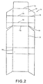
- Fig. 2 illustrates a plan view of a stamped piece of the sheeted material for a box board.
- the die-cutting machine comprises an upper slider 10, a lower platen 20, a chase 30 attached on the upper slider 10, a dead plate 40 attached on the lower platen 20.
- the chase 30 is one of general apparatuses to be accurately located and fixed on the upper slider 10 of the die-cutting machine
- the dead plate 40 is one of general apparatuses to be accurately located and fixed on the lower platen 20.
- the cutting die 50 fixed on the upper slider is constructed by fixing cutting blades (knife rules) 52 and rulings (creasing rules) 53 on a base plate 51.
- the base plate 51 is made of a veneer plate or a metal plate, on which fixing grooves 54 are formed by means of a laser-machining.
- both the cutting blades 52 and the rulings 53 are formed by bending a strip of plate material (steel rule) and inserted into grooves 54 formed on the base plate 51.
- a counter plate 60 fixed on the dead plate 40 is made of a metal plate with a thickness of about 1.5 mm.
- the counter plate 60 is provided as a flat receiving surface 62 except portions formed as hollows or recesses 61 corresponding to the rulings 53.
- an iron plate (not shown in the figure) of about 5 mm thickness is attached to the die-cutting machine, so that the cutting blades 52 become positioned at a surface of the iron plate when the cutting die 50 moves downward.
- the counter plate 60 of about 1.5 mm in thickness is used and thus a thickness of the dead plate 40 is adjusted to about 3.5 mm.
- the die-cutting machine so constructed is able to stamp a sheet of material 70 such as a synthetic resin film, a thin sheet of paper, and a sheet of box board into a desired shape by pressing the cutting blades 52 against the receiving surface 62 of the counter plate 60 by pulling down the cutting die 50 (i.e., from its resting position) after placing the sheet material 70 on the counter plate 60.
- a sheet of material 70 such as a synthetic resin film, a thin sheet of paper, and a sheet of box board
- Fig. 2 there is shown one of the examples of obtainable stamped pieces of the sheet material (hereinafter referred as a stamped sheet) by the die-cutting machine.
- the stamped sheet 71 is of desired shape and has cut lines 72 and ruled lines (creased lines) 73 (i.e., polygonal lines) as folds to bend.
- the cut line 72 is formed by contacting a tip of the cutting blades 52 on the receiving surface 62 of the counter plate 60 while the ruled line is formed by inserting a tip of the ruling 53 into the hollow 61.
- the counter plate 60 described above should be made of a material having an extremely high hardness (i.e., around HRC 50°), such as a high-hardness stainless steel. Therefore, it is a time-consuming job to make the hollows 61 on the counter plate 60 by a machining center and results in several disadvantages such as the high cost of production.
- the counter plate 60 is prepared cost effectively because it shortens its useful life by forming a recessed area as a result of press-contacting with the cutting blade 52.
- the cutting blade to be used in the cutting die described above is prepared typically from a band-shaped material having an extremely high hardness (i.e., around HRC 50°), so that it takes much time to cut the material into pieces having a predetermined length and bending each piece into a predetermined shape. It is noted that a spring-back can be occurred at the time of bending the cutting blade, so that a corrective action should be performed in consideration of the spring-back when the bending step is performed using a machine. Consequently, these operations are made in complicated steps.
- the present invention is attained by new concepts of: obtaining a high-hardness counter plate by using a cheap material having a comparatively low hardness, which is easily machined with less expensive to prepare a counter plate; and hardening only a portion thereof corresponding to a cutting blade by means of a laser irradiation.
- the counter plate of the present invention may be made of a material selected from any materials, typically a thin steel plate, to be hardened by means of a laser irradiation.
- a SK material as carbon tool steel may be used for obtaining a high hardness (i.e., about HRC 50°) by means of a laser irradiation.
- HRC 50° high hardness
- a thickness of the counter plate is in the range of 0.5 mm to 2 mm in consideration of forming the hollows thereon.
- hollows may be formed on the counter plate by way of the previously known cutting operations using a milling cutter or the like, or other operations using an etching, an electro-chemical machining, or the like.
- the hardening using the laser irradiation may be performed by the way of heating the material up to a predetermined temperature followed by cooling at a predetermined rate or over.
- a carbon dioxide laser beam machine for forming grooves on a base plate of the cutting die, which correspond to the cutting blades or the like may be also used in the process for machining the counter plate. In this case, however, a typical laser beam machine may be also applicable.
- the biggest advantage of the present invention is to provide a useful counter plate by hardening only portions thereof to be contacted with cutting blades of a cutting die. Furthermore, ditto for the formation of hollows, the hardening process is easily performed with the aid of CAD (computer-aided design) data used in the process of forming grooves of the base plate to be used for fixing cutting blades or the like, resulting that the machining operations can be down very easily. Accordingly, the counter plate can be provided by the process with less expensive as a consequence of simplified machining and of using a comparatively cheap material.
- CAD computer-aided design
- a necessary condition for the hardening process using a laser beam irradiation is to air-cooling after the irradiation.
- a coolant cooling water, liquid nitrogen, or the like may be sprayed on a front or back side of the target portion directly after the laser irradiation. In the case of spraying water on the surface, there is a problem of laser beam absorption.
- this kind of absorption can be of a negligible amount when the carbon dioxide laser is used because the target portion is well hardened through a water layer with a thickness of several millimeters.
- This kind of the cooling can be effectively applied on a very thin steel plate in a sense of preventing the deformation of the plate, and so on to be caused by the hardening.
- nozzle means it is preferable to use nozzle means to be moved in synchronization with a laser beam scanning.
- the hardening by irradiating the laser beam it is preferable to keep an absorptivity of the laser energy constant on a surface of the plate. If the general steel plate is used as-is, the hardness to stand contact with the cutting blade is obtained at the minimum.
- the absorptivity of the laser energy constant it is preferable to form a uniform layer on the surface by means of painting, printing, or the like. For example, it can be also performed by ejecting ink just at the front of a scanning position of the laser beam from an ink-jet nozzle. Alternatively, the surface may be polished.
- the material is deformed as a warp or the like to be caused by the hardening using the laser irradiation.
- the extent of the deformation can be reduced to a certain extent by means of cooling or the like.
- other type of hardened portion can be formed for canceling the warp of the whole material, for example the method of forming the hardened portion on the backside being opposed to the hardened portion of the surface, or the method of forming two hardened portions on the both sides of the backside being opposed to the hardened portion of the surface.
- the hardening can be performed from the backside using the laser irradiation when it is subjected to a thin steel plate especially of about 1 mm or less in thickness. If the hardening is performed on such material from its surface, for example, a center of the material suffers upward warping so as to make a protuberance on the surface. If the hardening is performed on such material from its backside, on the other hand, a center of the material suffers downward warping so as to make a hollow on the back, resulting in the advantage of making easy to deal with.
- the required level of quality of the cutting blade may be capable of being subjected to the hardening using the laser beam irradiation. Therefore, the material of the cutting blade may be a thin steel plate in general. Preferably, a SK material as carbon tool steel may be used for obtaining a high hardness (i.e., about HRC 50°) by the laser beam hardening. Considering of the formation of rust of a surface of the material, it is preferable to subject at least a surface thereof to plating. A thickness of the cutting blade may be the same as that of the conventional one, typically of the order of 0.5 mm to 3 mm.
- the method for forming the cutting edge of the cutting blade is not restricted in narrow limits but it is possible to form the cutting edge by one of the previously known operations such as cutting and forging.
- a cutting operation it is possible to machine a material to be provided as the cutting blade after hardening entirely.
- the material may be subjected to annealing after the machining and then only the cutting edge portion may be hardened by the laser irradiation.
- the hardened material is machined without annealing or with slightly annealing, it may be acceptable to slightly harden the cutting blade throughout within the scope of the present invention.
- the hardening of the cutting edge portion using a laser beam irradiation may be performed by irradiating the laser beam from the tip of the cutting edge to heat it up to the predetermined temperature and then cool it at the predetermined rate or over.
- a carbon dioxide laser beam machine for forming grooves on a base plate of the cutting die, which correspond to the cutting blades or the like, may be also used. In this case, however, some typical laser beam machines may be also applicable.
- the biggest advantage of the present invention is to provide a cutting die that allows easy processing and installation, in which at least the cutting edge of the cutting blade has a sufficient hardness as a result of easily hardening only the cutting edge. Furthermore, the hardening process is easily performed with the aid of CAD data used in the process of forming grooves of the base plate to be used for fixing cutting blades or the like, resulting that the machining operations can be down very easily. Accordingly, the cutting die can be provided by the process with less expensive as a consequence of simplified machining and of using a comparatively cheap material.
- the cutting blade comprises a base portion without being subjected to a substantial hardening and a hardened cutting edge portion.
- the base portion can be elastically deformed in a easy manner to absorb an impactive force to be applied on the cutting edge portion. It means that there is another advantage that a long wearing cutting edge portion can be obtained in accordance with present invention.
- the laser beam hardening against the cutting blade to be installed in the cutting die of the present invention is performed under the same conditions as that of the counter plate described above.
- FIG. 3 there is shown a schematic cross section of the die-cutting machine that uses a counter plate in accordance with the present invention.
- each part corresponding to that of the conventional die-cutting machine (FIG. 1) explained in the earlier section "Back Ground of the Invention" is designated as the same reference numeral.
- a counter plate 100 is fixed on a dead plate 60 of a lower platen 20, while a chase 30 and a cutting die 50 are attached on an upper slider 10.
- the cutting die 50 is manufactured by fixing a plurality of cutting blades 52 and a plurality of rulings 53 on a base plate 51 made of a veneer plate having a plurality of grooves 54 formed by means of a carbon dioxide laser beam machining.
- the cutting blades 52 and the rulings 53 are formed by the process including the steps of bending a thin strip of flexible material and inserting bent portions thereof respectively into the grooves so as to be secured therein.
- the counter plate 100 is made of an SK material of about 1.5 mm thickness and includes first portions that correspond to the rulings 53 and second portions that correspond to the cutting blades 52.
- the first portions are formed as hollows 101, while the second portions are provided as edge-bearing portions 102 which are prepared by means of a laser beam hardening.
- a surface hardness of the edge-bearing portion 102 is around Hv 180.
- the counter plate 100 except the edge-bearing portions 102 has a surface hardness of around Hv 180.
- the laser beam hardening applied in the present embodiment uses a carbon dioxide beam machine which is used for preparing the base plate as described above, under the conditions of: 500 W in output power; 10 inches in a focal length; and 2,400 mm/min. in a processing rate. Accordingly, the hardening process is easily performed with the aid of CAD data used in the process of forming grooves 54 of the base plate 51, resulting that the edge-bearing portions 102 can be obtained very easily. In this process, it is noted that there is no need to use additional devices, especially a cooling device.
- hollows 101 are formed by using a milling cutter.
- the counter plate 100 is easily processed because a hardness of SK material is comparatively not high. In this case, the process is also easily performed with the aid of CAD data described above.
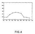
- FIG. 4 there is shown results of measuring the surface hardness (i.e., Vickers' hardness: Hv) of the counter plate 100 in the direction of an arrow A in FIG. 3 by using a Vickers' hardness tester under the conditions of a load weighting of 100g at a holding time of 30 seconds.
- a lateral axis represents coordinates along the axis A
- a vertical axis represents the obtained values of Vickers' hardness.
- the coordinates 10.02 - 10.41 corresponding to a width of the edge-bearing portion 102 take the values of Vickers' hardness in the range of about Hv 400 to about Hv 500, especially over Hv 500 in the middle. This hardness provides a sufficient strength of the cutting die 50 enough to guard against contact with the cutting blade 52.
- the counter plate of the present embodiment is prepared from a steel plate with a comparatively low hardness.
- the steel plate is easily machined with less expensive, and also a surface thereof is easily subjected to the hollow formation and the hardening process for providing an edge bearing portions, resulting that an extremely low cost counter plate.
- each hardened portion is formed as an arrow head in cross section, in which the width thereof is gradually decreased downward as shown in Fig. 3.
- the present invention is realized by new concepts including that only an edge-bearing portion is subjected to the hardening process using a laser irradiation, so that the following advantages are obtained. It means that the process for manufacturing a counter plate including the step of hardening only a contact portion of a cutting blade of a cutting die can be effectively used to a considerable degree because of the following reasons:
- a cheap counter plate with high durability can be materialized by the process including the steps of using a cheap material to be easily machined and hardening only a portion corresponding to a cutting blade by means of a laser irradiation to easily form a high hardness edge-bearing portion.
- FIG. 5 there is shown a schematic cross section of the die-cutting machine that uses a counter plate in accordance with the present invention.
- each part corresponding to that of the conventional die-cutting machine (FIG. 1) explained in the earlier section "Back Ground of the Invention" is designated as the same reference numeral.
- a cutting die 100 comprises cutting blades 102 and rulings 103 which are mounted securely on a base plate 101.
- the base plate 101 is made of a veneer plate having a plurality of grooves 104 formed by means of a carbon dioxide laser beam machining.
- cutting blades 102 and rulings 103 are formed by the process including the steps of bending a thin strip of flexible plate material and inserting bent portions thereof respectively into the grooves so as to be secured therein.
- the cutting die 100 is fixed on an upper slider 10 with a chase 30, while a counter plate 60 is fixed on a dead plate 60 of a lower platen 20 made of a plate material of about 1.5 mm in thickness. In the lower platen 20, furthermore, hollows 61 are formed on appropriate portions corresponding to the rulings 103, respectively.
- Each of the cutting blades 102 is formed as a band-shaped SK material of about 0.7 mm in thickness and mainly comprises a base portion 102a and an edge portion 102b.
- the base portion 102a is not hardened, while the edge portion 102b is hardened by a laser irradiation.
- the edge portion 102b is formed by the process including the steps of cutting a band-shaped material without hardening into a cutting edge portion 102b, roughly; cutting and bending the cutting edge blade 102 into a predetermined length so as to fit into a specified geometry of the above groove 104; inserting the cutting blade 102 into the groove 104 so as to be secured therein; and hardening the top portion thereof by a laser irradiation to obtain the hardened cutting edge portion 102b.
- a surface hardness of the cutting edge portion 102b is around Hv 500
- a surface hardness of the base portion 102a is around Hv 180.
- the laser beam hardening applied in the present embodiment uses a device for carbon dioxide beam machining, which is used for preparing the base plate as described above, under the conditions of: 500 W in output power; 10 inches in a focal length; and 2,400 mm/min. in a processing rate. Accordingly, the hardening process is easily performed with the aid of CAD data used in the process of forming grooves 104 of the base plate 101, resulting that the machining is performed very easily. In this machining, it is noted that there is no need to use additional devices, especially a cooling device.
- the steps of cutting and bending for preparing the above cutting blade 102 are easily performed because the SK material having not great hardness.
- the bending in particular is easily performed without a corrective action on a spring-back.
- a cutting die is constructed by the process including the steps of machining a cheap and easy-machining steel plate having lower hardness compared with that of the conventional one, instead of machining a high-hardness steel being used in the process for preparing the conventional cutting edge; and hardening only the cutting edge by means of a laser irradiation after fixing securely on the base plate, resulting in a very cheap cutting die.
- the present invention is realized by new concepts including that only the edge portion of the cutting blade is subjected to the hardening process using a laser irradiation. That is, it means that the process for manufacturing a counter plate including the step of hardening only the edge portion of the cutting blade can be effectively used to a considerable degree because of the following reasons:
- a cheap cutting die with high durability can be materialized by the process including the steps of using a cheap material to be easily machined and hardening only an edge portion of a cutting blade by means of a laser irradiation to easily form a high hardness cutting blade.
Description
Claims (8)
- A method for manufacturing a counter plate (100) for a cutting die (50) having cutting blades (52) and rulings (53) for stamping sheet material into a predetermined shape and making ruled lines thereon, the counter plate (100) being provided with recesses (101) corresponding to said rulings (53) and edge-bearing portions (102) corresponding to said cutting blades (52),
characterised in that
a thin steel plate is used as said counter plate (100),
said edge-bearing portions (102) are hardened by laser beam irradiation, and
deformations of said counter plate (100), caused by said laser beam irradiation, are corrected before or after said irradiation. - The method of claim 1, wherein the correction is performed by hardening using laser beam irradiation on the back of said counter plate (100).
- The method of claim 2, wherein the laser beam hardening on the back of said counter plate (100) is performed at portions corresponding to said edge-bearing portions (102).
- The method of claim 2, wherein the laser beam hardening on the back of said counter plate (100) is performed at both side areas of portions corresponding to said edge-bearing portions (102).
- The method of any preceding claim, wherein portions to be hardened by laser beam irradiation are pre-treated to keep their absorptivity for the laser energy constant.
- The method of any preceding claim, wherein portions irradiated by laser beam are cooled after said laser beam irradiation.
- The method of any preceding claim, wherein said laser beam irradiation is done using a carbon dioxide laser.
- The method of any preceding claim, wherein said laser beam irradiation is performed using CAD data that were used in forming grooves (104) for fixing said cutting blades (52) on said cutting die (50).
Applications Claiming Priority (6)
| Application Number | Priority Date | Filing Date | Title |
|---|---|---|---|
| JP330857/95 | 1995-12-19 | ||
| JP33085795A JPH09168999A (en) | 1995-12-19 | 1995-12-19 | Counter plate for blanking and manufacture thereof |
| JP33085795 | 1995-12-19 | ||
| JP2154/96 | 1996-01-10 | ||
| JP215496A JPH09193081A (en) | 1996-01-10 | 1996-01-10 | Trimming die for punching machine and its manufacture |
| JP215496 | 1996-01-10 |
Publications (2)
| Publication Number | Publication Date |
|---|---|
| EP0780199A1 EP0780199A1 (en) | 1997-06-25 |
| EP0780199B1 true EP0780199B1 (en) | 2002-03-27 |
Family
ID=26335479
Family Applications (1)
| Application Number | Title | Priority Date | Filing Date |
|---|---|---|---|
| EP19960114320 Expired - Lifetime EP0780199B1 (en) | 1995-12-19 | 1996-09-06 | Method of producing a counter plate |
Country Status (2)
| Country | Link |
|---|---|
| EP (1) | EP0780199B1 (en) |
| DE (1) | DE69620119T2 (en) |
Families Citing this family (5)
| Publication number | Priority date | Publication date | Assignee | Title |
|---|---|---|---|---|
| DE20116375U1 (en) * | 2001-10-05 | 2002-11-21 | Mm Packaging Trier Gmbh | Punching device for the production of folding boxes and packaging blanks |
| DE102004031421A1 (en) * | 2004-06-29 | 2006-02-16 | Böhler-Uddeholm Precision Strip GmbH & Co. KG | Cutting lines having cutting tools or punching knife |
| CN102009421A (en) * | 2010-07-12 | 2011-04-13 | 吴江市变压器厂有限公司 | Trimming die device for manufacturing transposition paperboard |
| US10994437B2 (en) * | 2014-12-31 | 2021-05-04 | Michigan Lasercut | Hardened steel counter-die |
| CN110712231B (en) * | 2019-12-10 | 2021-12-14 | 安徽鼎元新材料有限公司 | Equal-specification bar cutting device and method for rock wool belt processing |
Family Cites Families (10)
| Publication number | Priority date | Publication date | Assignee | Title |
|---|---|---|---|---|
| US5211084A (en) * | 1981-09-08 | 1993-05-18 | Ameritek, Inc. | Method of making a steel rule die |
| JPS61202734A (en) * | 1985-03-06 | 1986-09-08 | Takefu Tokushu Kozai Kk | Production of round tooth cutter |
| GB2180504B (en) * | 1985-09-19 | 1989-08-23 | Michel Said Achou | Creasing machines |
| JPS62116717A (en) * | 1985-11-18 | 1987-05-28 | Kobe Steel Ltd | Method and apparatus for laser heat treatment of plate-shaped member |
| IT1196856B (en) * | 1986-12-19 | 1988-11-25 | Fiat Auto Spa | PROCESSING PROCESS OF LARGE CAST IRON MOLDS PARTICULARLY FOR THE MOLDING OF VEHICLE SHEETS AND EQUIPMENT FOR ITS REALIZATION |
| AT394680B (en) * | 1988-02-03 | 1992-05-25 | Boehler Gmbh | LINE CUTTING KNIFE FOR THE PROCESSING OF FLAT MATERIAL |
| YU135290A (en) * | 1989-07-25 | 1992-12-21 | Schuler, Albert | HARDENING PROCEDURE FOR CUTTING EDGES OF SAWS, KNIVES AND PUNCHING TOOLS |
| US5370028A (en) * | 1989-08-31 | 1994-12-06 | Karl Marbach Gmbh & Co. | Strip steel punching and indenting tool |
| DE3929415A1 (en) * | 1989-09-05 | 1991-03-07 | Marbach Gmbh Karl | PUNCHING - SCREED PLATE |
| RU2004603C1 (en) * | 1990-04-17 | 1993-12-15 | Юрий Иванович Мулин | Method for thermal hardening of metal items by laser radiation |
-
1996
- 1996-09-06 EP EP19960114320 patent/EP0780199B1/en not_active Expired - Lifetime
- 1996-09-06 DE DE1996620119 patent/DE69620119T2/en not_active Expired - Fee Related
Also Published As
| Publication number | Publication date |
|---|---|
| DE69620119T2 (en) | 2002-11-28 |
| DE69620119D1 (en) | 2002-05-02 |
| EP0780199A1 (en) | 1997-06-25 |
Similar Documents
| Publication | Publication Date | Title |
|---|---|---|
| US6189414B1 (en) | Counter plate and cutting die for die cutting machine | |
| EP0541723B1 (en) | Shaving system | |
| EP2300192B1 (en) | Method and system for manufacturing intaglio printing plates for the production of security papers | |
| US20130220088A1 (en) | Punch Tool With a Stamp Supported in a Floating Manner | |
| US20050211032A1 (en) | Cutting technology for metal sheet | |
| US6476349B1 (en) | Strip guiding device | |
| JP6884794B2 (en) | Die-cutting device and die-cutting method | |
| EP0780199B1 (en) | Method of producing a counter plate | |
| US5211084A (en) | Method of making a steel rule die | |
| JPH0677920B2 (en) | Strip punching / pushing tool and strip punching / pushing tool adjustment method | |
| JPS5847523A (en) | Punching tool made of strip-like steel | |
| US6367302B1 (en) | Method for bending and cutting metal strip material | |
| US6479787B1 (en) | Laser unit and method for engraving articles to be included in cans | |
| EP1304179A1 (en) | Metal mold for press working | |
| US5201253A (en) | Shaving system | |
| EP0418893A2 (en) | Method of machining a press die | |
| CA2185088A1 (en) | Counter plate and cutting die for die-cutting machine | |
| JPH09168999A (en) | Counter plate for blanking and manufacture thereof | |
| JPH09193081A (en) | Trimming die for punching machine and its manufacture | |
| EP3765233B1 (en) | Laser assisted machining of sheet material | |
| CN106925671A (en) | Stamping mold and the process for stamping using the stamping mold | |
| EP0857538A1 (en) | Method for manufacturing rotary cutting tool and rotary cutting tool | |
| US5939135A (en) | General type press forming knife-mould made of plain, soft and thin material | |
| JPH10280032A (en) | Formation of quenched part | |
| KR102660364B1 (en) | Laser-assisted processing of sheet materials |
Legal Events
| Date | Code | Title | Description |
|---|---|---|---|
| PUAI | Public reference made under article 153(3) epc to a published international application that has entered the european phase |
Free format text: ORIGINAL CODE: 0009012 |
|
| AK | Designated contracting states |
Kind code of ref document: A1 Designated state(s): DE FR GB IT |
|
| 17P | Request for examination filed |
Effective date: 19971216 |
|
| 17Q | First examination report despatched |
Effective date: 20000703 |
|
| RTI1 | Title (correction) |
Free format text: METHOD OF PRODUCING A COUNTER PLATE |
|
| GRAG | Despatch of communication of intention to grant |
Free format text: ORIGINAL CODE: EPIDOS AGRA |
|
| GRAG | Despatch of communication of intention to grant |
Free format text: ORIGINAL CODE: EPIDOS AGRA |
|
| GRAG | Despatch of communication of intention to grant |
Free format text: ORIGINAL CODE: EPIDOS AGRA |
|
| GRAH | Despatch of communication of intention to grant a patent |
Free format text: ORIGINAL CODE: EPIDOS IGRA |
|
| GRAH | Despatch of communication of intention to grant a patent |
Free format text: ORIGINAL CODE: EPIDOS IGRA |
|
| REG | Reference to a national code |
Ref country code: GB Ref legal event code: IF02 |
|
| GRAA | (expected) grant |
Free format text: ORIGINAL CODE: 0009210 |
|
| AK | Designated contracting states |
Kind code of ref document: B1 Designated state(s): DE FR GB IT |
|
| REF | Corresponds to: |
Ref document number: 69620119 Country of ref document: DE Date of ref document: 20020502 |
|
| ET | Fr: translation filed | ||
| PLBE | No opposition filed within time limit |
Free format text: ORIGINAL CODE: 0009261 |
|
| STAA | Information on the status of an ep patent application or granted ep patent |
Free format text: STATUS: NO OPPOSITION FILED WITHIN TIME LIMIT |
|
| 26N | No opposition filed |
Effective date: 20021230 |
|
| PGFP | Annual fee paid to national office [announced via postgrant information from national office to epo] |
Ref country code: FR Payment date: 20040730 Year of fee payment: 9 |
|
| PGFP | Annual fee paid to national office [announced via postgrant information from national office to epo] |
Ref country code: GB Payment date: 20050915 Year of fee payment: 10 |
|
| PGFP | Annual fee paid to national office [announced via postgrant information from national office to epo] |
Ref country code: DE Payment date: 20051122 Year of fee payment: 10 |
|
| PGFP | Annual fee paid to national office [announced via postgrant information from national office to epo] |
Ref country code: IT Payment date: 20060930 Year of fee payment: 11 |
|
| PG25 | Lapsed in a contracting state [announced via postgrant information from national office to epo] |
Ref country code: DE Free format text: LAPSE BECAUSE OF NON-PAYMENT OF DUE FEES Effective date: 20070403 |
|
| GBPC | Gb: european patent ceased through non-payment of renewal fee |
Effective date: 20060906 |
|
| REG | Reference to a national code |
Ref country code: FR Ref legal event code: ST Effective date: 20070531 |
|
| PG25 | Lapsed in a contracting state [announced via postgrant information from national office to epo] |
Ref country code: GB Free format text: LAPSE BECAUSE OF NON-PAYMENT OF DUE FEES Effective date: 20060906 |
|
| PG25 | Lapsed in a contracting state [announced via postgrant information from national office to epo] |
Ref country code: FR Free format text: LAPSE BECAUSE OF NON-PAYMENT OF DUE FEES Effective date: 20061002 |
|
| PG25 | Lapsed in a contracting state [announced via postgrant information from national office to epo] |
Ref country code: FR Free format text: LAPSE BECAUSE OF NON-PAYMENT OF DUE FEES Effective date: 20050930 |
|
| PG25 | Lapsed in a contracting state [announced via postgrant information from national office to epo] |
Ref country code: IT Free format text: LAPSE BECAUSE OF NON-PAYMENT OF DUE FEES Effective date: 20070906 |