EP0780086A2 - Water delivery tube with reservoir - Google Patents
Water delivery tube with reservoir Download PDFInfo
- Publication number
- EP0780086A2 EP0780086A2 EP96402793A EP96402793A EP0780086A2 EP 0780086 A2 EP0780086 A2 EP 0780086A2 EP 96402793 A EP96402793 A EP 96402793A EP 96402793 A EP96402793 A EP 96402793A EP 0780086 A2 EP0780086 A2 EP 0780086A2
- Authority
- EP
- European Patent Office
- Prior art keywords
- fluid
- pump
- outlet
- section
- delivery tube
- Prior art date
- Legal status (The legal status is an assumption and is not a legal conclusion. Google has not performed a legal analysis and makes no representation as to the accuracy of the status listed.)
- Withdrawn
Links
Images

Classifications
-
- A—HUMAN NECESSITIES
- A47—FURNITURE; DOMESTIC ARTICLES OR APPLIANCES; COFFEE MILLS; SPICE MILLS; SUCTION CLEANERS IN GENERAL
- A47L—DOMESTIC WASHING OR CLEANING; SUCTION CLEANERS IN GENERAL
- A47L15/00—Washing or rinsing machines for crockery or tableware
- A47L15/42—Details
- A47L15/4214—Water supply, recirculation or discharge arrangements; Devices therefor
- A47L15/4219—Water recirculation
- A47L15/4221—Arrangements for redirection of washing water, e.g. water diverters to selectively supply the spray arms
Definitions
- the present invention is directed to washers, and more particularly to washers having a valve for alternating the flow of fluid between two fluid delivery tubes.
- washers In order to efficiently distribute wash fluid, many washers have two spray arms disposed at different heights within a wash area. Some of these washers direct the wash fluid to the spray arms simultaneously, while other washers direct the wash fluid to the spray arms alternately. If wash fluid is directed to the spray arms alternately, the size of the circulating pump and the wash fluid distribution circuit can be reduced.
- a washer utilizing the Milocco system has upper and lower fluid delivery tubes for respectively supplying wash fluid to the upper and lower spray arms.
- the upper fluid delivery tube is connected to the upper spray arm while the lower fluid delivery tube is connected to the lower spray arm. Accordingly, the upper fluid delivery tube is substantially longer than the lower fluid delivery tube and, thus, has a substantially larger interior volume.
- Wash fluid is pumped through the upper and lower fluid delivery tubes by a pump having an intake side and a delivery side.
- the flow of wash fluid from the delivery side of the pump is controlled by a valve.
- the valve includes a housing having an inlet connected to the delivery side of the pump and upper and lower outlets respectively connected to the inlets of the upper and lower fluid delivery tubes.
- a valve closing element within the housing has a stable unblocking position spaced from, but aligned with the upper outlet.
- a first phase of operation the pump directs wash fluid against the closing element, moving the closing element from the stable unblocking position to a first blocking position.
- the first blocking position closes the upper outlet, directing most of the wash fluid into the lower fluid delivery tube.
- a bypass channel allows some of the pumped wash fluid to bypass the closing element and enter the upper fluid delivery tube as well.
- the bypass wash fluid in the upper fluid delivery tube flows downward and moves the blocking element from the first blocking position to an unstable unblocking position spaced from, but aligned with the lower fluid delivery tube.
- a second phase of pump operation is started before the flow of bypass wash fluid stops and the blocking element moves away from the unstable unblocking position.
- wash fluid from the pump moves the closing element from the unstable unblocking position to a second blocking position closing the lower outlet, thereby directing the wash fluid into the upper fluid delivery tube.
- wash fluid flows downward from the upper fluid delivery tube.
- the pump is not returned to the first phase of operation until after the upper fluid delivery tube is drained.
- the closing element will move to the stable unblocking position aligned with the upper outlet.
- the closing element will again be moved to the first blocking position, closing the upper outlet and directing most of the wash fluid into the lower fluid delivery tube.
- wash fluid is alternately directed to the upper and lower fluid delivery tubes and, thus, the upper and lower spray arms.
- the timing for the starting and stopping of the pump is critical to the operation of the Milocco system.
- the timing for starting phase two of the pump operation is especially critical. If phase two of the pump operation is not started before the wash fluid completely drains from the upper fluid delivery tube, the closing element will move away from the unstable unblocking position and move towards the stable unblocking position. As a result, the closing element will move to the first blocking position rather than the second blocking position when phase two of the pump operation is finally started, resulting in the blockage of the upper outlet instead of the lower outlet.
- the amount of time required to drain the upper fluid delivery tube is small. Accordingly, the pause between phase one and phase two of the pump operation is short. A short pause imposes a tight timing tolerance on a controller for the pump. Inexpensive electro-mechanical controllers often cannot meet the timing tolerance. Therefore, expensive electronic controllers such as a microprocessor-based programmable controllers are usually used to control a Milocco system. For this reason, there is a need in the art for an apparatus that increases the timing tolerance imposed on a controller for a pump in a Milocco system. The present invention is directed to such an apparatus.
- a fluid delivery tube for use with a washer having a sprayer and a valve with an inlet passage and first and second outlet passages.
- the fluid delivery tube has an inlet section, a reservoir section and an outlet section.
- the inlet section has an inlet opening for communication with the second outlet passage of the valve.
- the outlet section has an outlet opening for communication with the sprayer.
- the reservoir section is located between the inlet section and the outlet section and has a cross-sectional area that is greater than the cross-sectional area of the inlet opening and greater than the cross-sectional area of the outlet opening.
- a washer having a fluid delivery tube, a hollow spray arm, a pump for pumping fluid and a valve for directing fluid from the pump.
- the valve includes a housing and a closing element.
- the housing has an inlet passage in communication with the pump and first and second outlet passages.
- the closing element is located within the housing and is movable to a first blocking position that substantially closes the second outlet passage and is movable to a second blocking position that closes the first outlet passage.
- the fluid delivery tube has an inlet section, a reservoir section and an outlet section.
- the inlet section has an inlet opening in communication with the second outlet passage of the valve.
- the outlet section has an outlet opening in communication with the interior of the spray arm.
- the reservoir is located between the inlet section and the outlet section and has a cross-sectional area that is greater than the cross-sectional area of the inlet opening and greater than the cross-sectional area of the outlet opening.
- a washer having lower and upper delivery tubes, lower and upper hollow spray arms for spraying fluid, a pump for pumping fluid to the lower and upper spray arms and a valve.
- the valve directs fluid from the pump to the lower and upper spray arms so as to alternate fluid flow between the lower and upper spray arms.
- the valve includes a housing, a closing element and a bypass means.
- the housing has an inlet passage in communication with the pump and has first and second outlet passages.
- the closing element within the housing moves in response to a first stoppage of the pump from a blocking position that substantially closes the second outlet passage to an unstable unblocking position.
- the closing element is held in the unstable unblocking position by a reverse flow of fluid that enters the second outlet passage.
- the bypass means allows fluid to exit the second outlet passage when the closing element is in the blocking position.
- the lower delivery tube has an inner section with an inner opening in communication with the first outlet passage of the valve and has an outer section with an outer opening in communication with the interior of the lower spray arm.
- the upper delivery tube has a reservoir section, an inlet section and an outlet section.
- the inlet section has an inlet opening in communication with the second outlet passage of the valve, while the outlet section has an outlet opening in communication with the interior of the upper spray arm.
- the upper delivery tube retains fluid that passes through the bypass means when the closing element is in the blocking position.
- the upper delivery tube discharges the retained fluid into the second outlet passage of the valve upon the first stoppage of the pump and thereby creates the reverse flow of fluid.
- the reservoir section provides sufficient volume for retaining fluid when the closing element is in the blocking position so as to increase the duration of the reverse flow of fluid and therefore the amount of time the closing element is in the unstable unblocking position.
- the washer 10 generally includes a wash tub 20, a first or lower spray arm 30, a second or upper spray'arm 40, a first or lower fluid delivery tube 50, a second or upper fluid delivery tube 60, a pump 70 and a controller 80.
- the wash tub 20 has a lower wash area 22 with a lower rack 24 and an upper wash area 25 with an upper rack 27. Both the lower and upper racks 24, 27 hold objects to be washed, such as dishes, silverware, glasses and cookware.
- the lower portion of the wash tub 20 defines a sump 28 for collecting wash fluid. Located in the sump is an inlet to the pump 70.
- the pump 70 has an impeller 73 driven by a motor 75.
- An outlet 72 from the pump 70 is connected to a valve 100 which distributes wash fluid to the lower and upper fluid delivery tubes 50,60.
- the lower fluid delivery tube 50 has an inlet section 51 with an opening that is in communication with a first outlet passage 150 of the valve 100.
- the lower fluid delivery tube 50 is substantially straight and is relatively short in length. Accordingly, the interior volume of the lower fluid delivery tube 50 is relatively small.
- An opening in an outlet section 52 of the lower fluid delivery tube 50 is in communication with a central opening in the lower spray arm 30, which is substantially hollow. Disposed along the top surface of the lower spray arm 30 are a plurality of upwardly directed openings. Wash fluid delivered to the lower spray arm 30 through the lower fluid delivery tube 50 projects through these openings in a series of upwardly directed sprays of wash fluid. These upwardly-directed sprays enter the lower wash area 22 and impinge upon the objects in the lower rack 24, loosening food particles and other material adhering thereto.
- the upper fluid delivery tube 60 has an inlet section 61 with an inlet opening that is in communication with a second outlet passage 160 of the valve 100.
- An outlet opening in an outlet section 62 of the upper fluid delivery tube 60 is in communication with a central opening in the upper spray arm 40, which is also substantially hollow.
- Disposed along the bottom surface of the upper spray arm 40 are a plurality of downwardly directed openings. Wash fluid delivered to the upper spray arm 40 through the upper fluid delivery tube 60 projects through these openings in a series of downwardly directed sprays of wash fluid. These downwardly-directed sprays enter the upper wash area 25 and impinge upon the objects in the upper rack 27, loosening food particles and other material adhering thereto.
- the upper fluid delivery tube 60 In contrast to the lower fluid delivery tube 50, the upper fluid delivery tube 60 is long and generally C-shaped.
- the inlet section 61 of the upper fluid delivery tube 60 has a cylindrical portion that is horizontally oriented and contains the inlet opening. After the cylindrical portion, the inlet section 61 reduces into a slightly more narrow tubular portion, which extends out horizontally and then curves outward and upward so as to be vertically positioned. After the tubular portion, the inlet section 61 expands and is joined with a reservoir section 64, which first extends upward and then curves inward so as to be substantially horizontal. Accordingly, the reservoir section 64 substantially has an inverted L-shape.
- the reservoir section 64 After extending inward for a distance, the reservoir section 64 is joined with the outlet section 62, which narrows into an elliptical portion. After the elliptical portion, the outlet section 62 expands slightly and turns downward in an end portion where the outlet opening is located.
- the cross-sectional area of the reservoir section 64 is substantially greater than the cross-sectional area of either the inlet opening or the outlet opening. In a preferred embodiment of the present invention, the cross-sectional area of the reservoir section 64 is at least twice the cross-sectional area of either the inlet opening or the outlet opening.
- the valve 100 is shown as it appears when the pump 70 has been idle for an extended period of time.
- the valve 100 generally includes a housing 105 with the second outlet passage 160, the first outlet passage 150 and an inlet passage 101 connected to the outlet 72 from the pump 70.
- a bypass channel 110 leads from the inlet passage 101 to the outer portion of the second outlet passage 160.
- the bypass channel 110 has a cross-sectional area substantially smaller than either the first or second outlet passages 150,160.
- a spherical closing element 180 resting on a guide 190 that slopes downward from an upper end 191 located below the first outlet passage 150 to a lower end 193 located below the second outlet passage 160.
- the closing element 180 is made from a material having a specific gravity greater than the wash fluid. Accordingly, the closing element 180 naturally gravitates towards the lower end 193.
- the closing element 180 is stable and is not blocking either the second outlet passage 160 or the first outlet passage 150, i.e., the closing element is in a stable unblocking position. In the stable unblocking position, the closing element 180 is aligned below the second outlet passage 160.
- the valve 100 operates to alternately direct wash fluid from the pump 70 to the lower and upper delivery tubes 50,60.
- the valve 100 operates in response to a cycling of the pump 70 through four phases: a first phase of operation, a first phase of non-operation, a second phase of operation and a second phase of non-operation.
- the cycling of the pump 70 is accomplished by the controller 80 (shown in Fig.1), which starts and stops the motor 75.
- the controller 80 is an electro-mechanical or electronic controller known in the prior art.
- An example of such an electro-mechanical controller is the controller disclosed in assignee's application 08/383,055 which has just recently been allowed.
- the closing element 180 is in the stable unblocking position when the pump 70 has been idle for an extended period of time.
- the pump 70 enters the first phase of operation.
- the pump 70 directs wash fluid against the closing element 180, moving the closing element 180 from the stable unblocking position to a first blocking position shown in Fig.4.
- the closing element 180 is pressed against the inner portion of the second outlet passage 160, substantially blocking the flow of wash fluid through the second outlet passage 160.
- most of the wash fluid from the pump 70 flows through the first outlet passage 150 and the lower fluid delivery tube 50 and enters the lower spray arm 30.
- the wash fluid then projects through the upwardly-directed openings in the lower spray arm 30 and enters the lower wash area 22.
- bypass wash fluid enters and passes through the inlet section 61 of the upper fluid delivery tube 60 and proceeds into the reservoir section 64.
- the bypass wash fluid continues to enter the upper fluid delivery tube 60 and fill the volume of the reservoir section 64 until the pump 70 is stopped or the hydrostatic pressure exerted by the wash fluid in the upper fluid delivery tube 60 equals the pressure of the wash fluid entering the upper fluid delivery tube 60.
- the size of the bypass channel 110 is limited in relation to the capacity of the pump 70 so as to allow the hydrostatic pressure of the wash fluid -in the upper fluid delivery tube 60 to stop the flow of bypass wash fluid before the bypass wash fluid completely fills the upper fluid delivery tube 60 and exits through the upper spray arm 40.
- bypass channel 110 can be replaced by other arrangements that permit a small amount of wash fluid to bypass the closing element 180, enter the upper fluid delivery tube 60 and fill the reservoir section 64.
- the inner portion of the second outlet passage 160 can be made irregular so that the closing element 180 does not completely seal the inner portion when the closing element 180 is in the first blocking position.
- the pump 70 enters the first phase of non-operation.
- the bypass wash fluid in the upper fluid delivery tube 60 and the wash fluid in the lower fluid delivery tube 50 flow by gravity back into the valve 100.
- gravity urges the closing element 180 to move away from the first blocking position of Fig.4.
- the force of gravity on the closing element 180 would, by itself, move the closing element 180 back to the stable unblocking position.
- the flow of bypass wash' fluid from the upper fluid delivery tube 60 exerts a substantial hydrostatic pressure on the closing element 180 and, instead, moves the closing element 180 to an unstable unblocking position shown in Fig.5.
- the flow of wash fluid from the lower fluid delivery tube 50 also exerts a force on the closing element 180, but this force is small since the amount of wash fluid in the lower delivery tube 50 is negligible.
- the closing element 180 In the-unstable unblocking position, the closing element 180 is resting on the upper end 191 of the guide 190 and is spaced from, but aligned with, the first outlet passage 150. This position is unstable because the closing element 180 would, absent the flow of bypass wash fluid, slide along the guide 190 and return to the stable unblocking position at the lower end 193 of the guide 190.
- the pump 70 is started by the controller 80 before the expiration of a first period of time, which is the time it takes for the bypass wash fluid to stop flowing from the upper fluid delivery tube 60. When the pump 70 is again started, the pump enters the second phase of operation.
- the pump 70 directs wash fluid against the closing element 180, moving the closing element 180 from the unstable unblocking position shown in Fig. 5 to a second blocking position shown in Fig.6.
- the closing element 180 In the second blocking position, the closing element 180 is pressed against the inner portion of the first outlet passage 150, blocking the flow of wash fluid through the first outlet passage 150.
- the wash fluid from the pump 70 flows through the second outlet passage 160 and into the upper fluid delivery tube 60.
- the wash fluid exits the upper fluid delivery tube 60 and enters the upper spray arm 40.
- the wash fluid projects through the downwardly-directed openings in the upper spray arm 40 and enters the upper wash area 25.
- the upper fluid delivery tube 60 including the reservoir section 64, fills with wash fluid.
- the pump 70 When the pump 70 is stopped by the controller 80, the pump enters the second phase of non-operation.
- the wash fluid in the upper fluid delivery tube 60 flows by gravity back into the valve 100.
- gravity urges the closing element 180 to move away from the second blocking position.
- the force of gravity on the closing element 180 would, by itself, move the closing element 180 back to the stable unblocking position.
- the closing element 180 is prevented from moving past the unstable unblocking position by the hydrostatic pressure exerted by the flow of wash fluid from the upper fluid delivery tube 60. If the pump 70 was started before the flow of wash fluid from the upper fluid delivery tube 60 ceased, the closing element 180 would be moved back to the second blocking position as occurs in the second phase of operation.
- the duration of the second phase of non-operation is greater than a second period of time, which is the time it takes for the wash fluid to drain from the upper fluid delivery tube 60 and for the closing element 180 to subsequently move to the stable unblocking position.
- a second period of time which is the time it takes for the wash fluid to drain from the upper fluid delivery tube 60 and for the closing element 180 to subsequently move to the stable unblocking position.
- wash fluid is supplied to the lower spray arm 30 during the first phase of operation of the pump 70 and wash fluid is supplied to the upper spray arm 40 during the second phase of operation of the pump 70.
- the controller 80 does not have to be programmed to continuously cycle the pump 70 through the four phases so as to continuously alternate the supply of wash fluid to the lower and upper spray arms 30,40.
- the controller 80 can be programmed to alternate the supply of wash fluid to the lower and upper spray arms 30,40 for a period of time and then supply only one of the spray arms for the remainder of the operation of the washer 10, or the controller 80 can be programmed to only supply wash fluid to the lower spray arm 30.
- the foregoing is accomplished by programming the controller 80 to stop progressing the pump 70 to subsequent phases. It should be appreciated, however, that wash fluid cannot be supplied only to the upper spray arm 40 because the pump 70 has to progress through the first phase of operation and first phase of non-operation in order to reach the second phase of operation wherein wash fluid is supplied to the upper spray arm 40.
- the controller 80 can also be programmed to change the duration wash fluid is supplied to a particular spray arm by changing the durations of the first and second phases of operation.
- the pauses between the changes in supply to the spray arms, i.e., the first and second phases of non-operation, can also be changed, but only to an extent.
- the pause between supplying wash fluid to the lower spray arm 30 and supplying wash fluid to the upper spray arm 40, i.e., the first phase of non-operation cannot be greater than the first period of time. However, the first phase of non-operation can be less than the first period of time.
- the pause between supplying wash fluid to the upper spray arm 40 and supplying wash fluid to the lower spray arm 30, i.e., the second phase of non-operation, cannot be less than the second period of time.
- the second phase of non-operation can have a duration greater than the second period of time.
- the stopping and starting of the pump 70 to switch the flow of wash fluid from the lower spray arm 30 to the upper spray arm 40 is the most stringent operating parameter that has to be met by the controller 80 because the time between the stopping and the starting of the pump 70 i.e., the first period of time, is short. Accordingly, the first period of time determines the timing tolerance of the controller 80. Since the first period of time is the time it takes for the bypass wash fluid to stop flowing from the upper fluid delivery tube 60, the first period of time is a function of the volume of the upper fluid delivery tube 60. The volume of the upper fluid delivery tube 60 is significantly greater than the volume of prior art upper fluid delivery tubes because of the reservoir section 64.
- the time it takes for bypass wash fluid to stop flowing from the upper fluid delivery tube 60 of the present invention is significantly greater than the time it takes for bypass wash fluid to stop flowing from prior art upper fluid delivery tubes.
- the timing tolerance imposed on the controller 80 is greater than the timing tolerance imposed on the electronic controllers used in prior art Milocco systems. This increase in timing tolerance permits the controller 80 to be a conventional electro-mechanical controller instead of a sophisticated electronic controller. Of course, a sophisticated electronic controller can also be used in the washer 10, which has the upper fluid delivery tube 60 of the present invention.
Landscapes
- Engineering & Computer Science (AREA)
- Water Supply & Treatment (AREA)
- Cleaning By Liquid Or Steam (AREA)
- Nozzles (AREA)
Abstract
A fluid delivery tube for a washer having a hollow spray arm and a valve with an inlet passage and first and second outlet passages. The fluid delivery tube has an inlet section, a reservoir section and an outlet section. The inlet section has an inlet opening for communication with the second outlet passage of the valve. The outlet section has an outlet opening for communication with the interior of the spray arm. The reservoir section is located between the inlet section and the outlet section and has a cross-sectional area that is greater than the cross-sectional area of the inlet opening and greater than the cross-sectional area of the outlet opening.
Description
- The present invention is directed to washers, and more particularly to washers having a valve for alternating the flow of fluid between two fluid delivery tubes.
- In order to efficiently distribute wash fluid, many washers have two spray arms disposed at different heights within a wash area. Some of these washers direct the wash fluid to the spray arms simultaneously, while other washers direct the wash fluid to the spray arms alternately. If wash fluid is directed to the spray arms alternately, the size of the circulating pump and the wash fluid distribution circuit can be reduced.
- One system for alternating the flow of wash fluid to two spray arms is the system disclosed in U.S. Patent No. 4,741,353 to Milocco, incorporated herein by reference. A method for controlling a washing cycle in a washer having a Milocco system is disclosed in U.S. Patent No. 5,264,043 also to Milocco, incorporated herein by reference. A washer utilizing the Milocco system has upper and lower fluid delivery tubes for respectively supplying wash fluid to the upper and lower spray arms. The upper fluid delivery tube is connected to the upper spray arm while the lower fluid delivery tube is connected to the lower spray arm. Accordingly, the upper fluid delivery tube is substantially longer than the lower fluid delivery tube and, thus, has a substantially larger interior volume. Wash fluid is pumped through the upper and lower fluid delivery tubes by a pump having an intake side and a delivery side. The flow of wash fluid from the delivery side of the pump is controlled by a valve. The valve includes a housing having an inlet connected to the delivery side of the pump and upper and lower outlets respectively connected to the inlets of the upper and lower fluid delivery tubes. A valve closing element within the housing has a stable unblocking position spaced from, but aligned with the upper outlet.
- In a first phase of operation, the pump directs wash fluid against the closing element, moving the closing element from the stable unblocking position to a first blocking position. The first blocking position closes the upper outlet, directing most of the wash fluid into the lower fluid delivery tube. A bypass channel, however, allows some of the pumped wash fluid to bypass the closing element and enter the upper fluid delivery tube as well. When the pump is stopped, the bypass wash fluid in the upper fluid delivery tube flows downward and moves the blocking element from the first blocking position to an unstable unblocking position spaced from, but aligned with the lower fluid delivery tube. A second phase of pump operation is started before the flow of bypass wash fluid stops and the blocking element moves away from the unstable unblocking position. In the second phase of operation, wash fluid from the pump moves the closing element from the unstable unblocking position to a second blocking position closing the lower outlet, thereby directing the wash fluid into the upper fluid delivery tube.
- When the pump is stopped, wash fluid flows downward from the upper fluid delivery tube. However, the pump is not returned to the first phase of operation until after the upper fluid delivery tube is drained. As a result, the closing element will move to the stable unblocking position aligned with the upper outlet. Thus, when the first phase of pump operation is started again, the closing element will again be moved to the first blocking position, closing the upper outlet and directing most of the wash fluid into the lower fluid delivery tube.
- In the foregoing manner, wash fluid is alternately directed to the upper and lower fluid delivery tubes and, thus, the upper and lower spray arms. As can be appreciated, the timing for the starting and stopping of the pump is critical to the operation of the Milocco system. The timing for starting phase two of the pump operation is especially critical. If phase two of the pump operation is not started before the wash fluid completely drains from the upper fluid delivery tube, the closing element will move away from the unstable unblocking position and move towards the stable unblocking position. As a result, the closing element will move to the first blocking position rather than the second blocking position when phase two of the pump operation is finally started, resulting in the blockage of the upper outlet instead of the lower outlet.
- In the Milocco system, the amount of time required to drain the upper fluid delivery tube is small. Accordingly, the pause between phase one and phase two of the pump operation is short. A short pause imposes a tight timing tolerance on a controller for the pump. Inexpensive electro-mechanical controllers often cannot meet the timing tolerance. Therefore, expensive electronic controllers such as a microprocessor-based programmable controllers are usually used to control a Milocco system. For this reason, there is a need in the art for an apparatus that increases the timing tolerance imposed on a controller for a pump in a Milocco system. The present invention is directed to such an apparatus.
- In accordance with the present invention, a fluid delivery tube is provided for use with a washer having a sprayer and a valve with an inlet passage and first and second outlet passages. The fluid delivery tube has an inlet section, a reservoir section and an outlet section. The inlet section has an inlet opening for communication with the second outlet passage of the valve. The outlet section has an outlet opening for communication with the sprayer. The reservoir section is located between the inlet section and the outlet section and has a cross-sectional area that is greater than the cross-sectional area of the inlet opening and greater than the cross-sectional area of the outlet opening.
- Also in accordance with the present invention, a washer is provided having a fluid delivery tube, a hollow spray arm, a pump for pumping fluid and a valve for directing fluid from the pump. The valve includes a housing and a closing element. The housing has an inlet passage in communication with the pump and first and second outlet passages. The closing element is located within the housing and is movable to a first blocking position that substantially closes the second outlet passage and is movable to a second blocking position that closes the first outlet passage. The fluid delivery tube has an inlet section, a reservoir section and an outlet section. The inlet section has an inlet opening in communication with the second outlet passage of the valve. The outlet section has an outlet opening in communication with the interior of the spray arm. The reservoir is located between the inlet section and the outlet section and has a cross-sectional area that is greater than the cross-sectional area of the inlet opening and greater than the cross-sectional area of the outlet opening. When the closing element is in the second blocking position, the reservoir section conducts fluid from the inlet section to the outlet section and thence the spray arm. When the closing element is in the first blocking position, the reservoir section holds fluid.
- Also in accordance with the present invention, a washer is provided having lower and upper delivery tubes, lower and upper hollow spray arms for spraying fluid, a pump for pumping fluid to the lower and upper spray arms and a valve. The valve directs fluid from the pump to the lower and upper spray arms so as to alternate fluid flow between the lower and upper spray arms. The valve includes a housing, a closing element and a bypass means. The housing has an inlet passage in communication with the pump and has first and second outlet passages. The closing element within the housing moves in response to a first stoppage of the pump from a blocking position that substantially closes the second outlet passage to an unstable unblocking position. The closing element is held in the unstable unblocking position by a reverse flow of fluid that enters the second outlet passage. The bypass means allows fluid to exit the second outlet passage when the closing element is in the blocking position.
- The lower delivery tube has an inner section with an inner opening in communication with the first outlet passage of the valve and has an outer section with an outer opening in communication with the interior of the lower spray arm. The upper delivery tube has a reservoir section, an inlet section and an outlet section. The inlet section has an inlet opening in communication with the second outlet passage of the valve, while the outlet section has an outlet opening in communication with the interior of the upper spray arm. The upper delivery tube retains fluid that passes through the bypass means when the closing element is in the blocking position. The upper delivery tube discharges the retained fluid into the second outlet passage of the valve upon the first stoppage of the pump and thereby creates the reverse flow of fluid. The reservoir section provides sufficient volume for retaining fluid when the closing element is in the blocking position so as to increase the duration of the reverse flow of fluid and therefore the amount of time the closing element is in the unstable unblocking position.
- The features, aspects, and advantages of the present invention will become better understood with regard to the following description, appended claims, and accompanying drawings where:
- Fig. 1 shows a schematic view of a washer having a fluid delivery tube in accordance with the present invention;
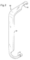
- Fig. 2 shows the delivery tube of the present invention; and
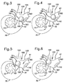
- Figs. 3 through 6 are enlarged schematic views illustrating the different operating positions of a valve used in conjunction with the fluid delivery tube of the present invention.
- It should be noted that in the detailed description which follows, identical components have the same reference numerals, regardless whether they are shown in different embodiments of the present invention. It should also be noted that in order to clearly and concisely disclose the present invention, the drawings may not necessarily be to scale and certain features of the invention may be shown in somewhat schematic form.
- Referring now to Fig. 1, there is shown a
washer 10, such as a dishwasher, having the apparatus of the present invention. Thewasher 10 generally includes awash tub 20, a first orlower spray arm 30, a second orupper spray'arm 40, a first or lowerfluid delivery tube 50, a second or upperfluid delivery tube 60, apump 70 and acontroller 80. Thewash tub 20 has alower wash area 22 with alower rack 24 and anupper wash area 25 with anupper rack 27. Both the lower andupper racks wash tub 20 defines asump 28 for collecting wash fluid. Located in the sump is an inlet to thepump 70. Thepump 70 has animpeller 73 driven by amotor 75. Anoutlet 72 from thepump 70 is connected to avalve 100 which distributes wash fluid to the lower and upperfluid delivery tubes - The lower
fluid delivery tube 50 has aninlet section 51 with an opening that is in communication with afirst outlet passage 150 of thevalve 100. The lowerfluid delivery tube 50 is substantially straight and is relatively short in length. Accordingly, the interior volume of the lowerfluid delivery tube 50 is relatively small. An opening in anoutlet section 52 of the lowerfluid delivery tube 50 is in communication with a central opening in thelower spray arm 30, which is substantially hollow. Disposed along the top surface of thelower spray arm 30 are a plurality of upwardly directed openings. Wash fluid delivered to thelower spray arm 30 through the lowerfluid delivery tube 50 projects through these openings in a series of upwardly directed sprays of wash fluid. These upwardly-directed sprays enter thelower wash area 22 and impinge upon the objects in thelower rack 24, loosening food particles and other material adhering thereto. - The upper
fluid delivery tube 60 has aninlet section 61 with an inlet opening that is in communication with asecond outlet passage 160 of thevalve 100. An outlet opening in anoutlet section 62 of the upperfluid delivery tube 60 is in communication with a central opening in theupper spray arm 40, which is also substantially hollow. Disposed along the bottom surface of theupper spray arm 40 are a plurality of downwardly directed openings. Wash fluid delivered to theupper spray arm 40 through the upperfluid delivery tube 60 projects through these openings in a series of downwardly directed sprays of wash fluid. These downwardly-directed sprays enter theupper wash area 25 and impinge upon the objects in theupper rack 27, loosening food particles and other material adhering thereto. - Referring now to Fig. 2, there is shown a drawing of the upper
fluid delivery tube 60. In contrast to the lowerfluid delivery tube 50, the upperfluid delivery tube 60 is long and generally C-shaped. Theinlet section 61 of the upperfluid delivery tube 60 has a cylindrical portion that is horizontally oriented and contains the inlet opening. After the cylindrical portion, theinlet section 61 reduces into a slightly more narrow tubular portion, which extends out horizontally and then curves outward and upward so as to be vertically positioned. After the tubular portion, theinlet section 61 expands and is joined with areservoir section 64, which first extends upward and then curves inward so as to be substantially horizontal. Accordingly, thereservoir section 64 substantially has an inverted L-shape. After extending inward for a distance, thereservoir section 64 is joined with theoutlet section 62, which narrows into an elliptical portion. After the elliptical portion, theoutlet section 62 expands slightly and turns downward in an end portion where the outlet opening is located. The cross-sectional area of thereservoir section 64 is substantially greater than the cross-sectional area of either the inlet opening or the outlet opening. In a preferred embodiment of the present invention, the cross-sectional area of thereservoir section 64 is at least twice the cross-sectional area of either the inlet opening or the outlet opening. - Referring now to Fig.3, the
valve 100 is shown as it appears when thepump 70 has been idle for an extended period of time. Thevalve 100 generally includes ahousing 105 with thesecond outlet passage 160, thefirst outlet passage 150 and aninlet passage 101 connected to theoutlet 72 from thepump 70. Abypass channel 110 leads from theinlet passage 101 to the outer portion of thesecond outlet passage 160. Thebypass channel 110 has a cross-sectional area substantially smaller than either the first or second outlet passages 150,160. - Located within the
valve chamber 100 is aspherical closing element 180 resting on aguide 190 that slopes downward from anupper end 191 located below thefirst outlet passage 150 to alower end 193 located below thesecond outlet passage 160. Theclosing element 180 is made from a material having a specific gravity greater than the wash fluid. Accordingly, theclosing element 180 naturally gravitates towards thelower end 193. At thelower end 193, theclosing element 180 is stable and is not blocking either thesecond outlet passage 160 or thefirst outlet passage 150, i.e., the closing element is in a stable unblocking position. In the stable unblocking position, theclosing element 180 is aligned below thesecond outlet passage 160. - The
valve 100 operates to alternately direct wash fluid from thepump 70 to the lower andupper delivery tubes valve 100 operates in response to a cycling of thepump 70 through four phases: a first phase of operation, a first phase of non-operation, a second phase of operation and a second phase of non-operation. The cycling of thepump 70 is accomplished by the controller 80 (shown in Fig.1), which starts and stops themotor 75. Thecontroller 80 is an electro-mechanical or electronic controller known in the prior art. An example of such an electro-mechanical controller is the controller disclosed in assignee's application 08/383,055 which has just recently been allowed. - As stated above, the
closing element 180 is in the stable unblocking position when thepump 70 has been idle for an extended period of time. When thepump 70 is subsequently started by thecontroller 80, thepump 70 enters the first phase of operation. In the first phase of operation, thepump 70 directs wash fluid against theclosing element 180, moving theclosing element 180 from the stable unblocking position to a first blocking position shown in Fig.4. In the first blocking position, theclosing element 180 is pressed against the inner portion of thesecond outlet passage 160, substantially blocking the flow of wash fluid through thesecond outlet passage 160. As a result, most of the wash fluid from thepump 70 flows through thefirst outlet passage 150 and the lowerfluid delivery tube 50 and enters thelower spray arm 30. The wash fluid then projects through the upwardly-directed openings in thelower spray arm 30 and enters thelower wash area 22. - Although most of the wash fluid flows through the lower
fluid delivery tube 50, some of the wash fluid is able to bypass theclosing element 180 and flow through thesecond outlet passage 160 by travelling through thebypass channel 110. This bypass wash fluid enters and passes through theinlet section 61 of the upperfluid delivery tube 60 and proceeds into thereservoir section 64. The bypass wash fluid continues to enter the upperfluid delivery tube 60 and fill the volume of thereservoir section 64 until thepump 70 is stopped or the hydrostatic pressure exerted by the wash fluid in the upperfluid delivery tube 60 equals the pressure of the wash fluid entering the upperfluid delivery tube 60. The size of thebypass channel 110 is limited in relation to the capacity of thepump 70 so as to allow the hydrostatic pressure of the wash fluid -in the upperfluid delivery tube 60 to stop the flow of bypass wash fluid before the bypass wash fluid completely fills the upperfluid delivery tube 60 and exits through theupper spray arm 40. - It should be appreciated that the
bypass channel 110 can be replaced by other arrangements that permit a small amount of wash fluid to bypass theclosing element 180, enter the upperfluid delivery tube 60 and fill thereservoir section 64. For example, the inner portion of thesecond outlet passage 160 can be made irregular so that theclosing element 180 does not completely seal the inner portion when theclosing element 180 is in the first blocking position. - When the
pump 70 is stopped by thecontroller 80, thepump 70 enters the first phase of non-operation. At the beginning of the first phase of non-operation, the bypass wash fluid in the upperfluid delivery tube 60 and the wash fluid in the lowerfluid delivery tube 50 flow by gravity back into thevalve 100. In addition, gravity urges theclosing element 180 to move away from the first blocking position of Fig.4. The force of gravity on theclosing element 180 would, by itself, move theclosing element 180 back to the stable unblocking position. However, the flow of bypass wash' fluid from the upperfluid delivery tube 60 exerts a substantial hydrostatic pressure on theclosing element 180 and, instead, moves theclosing element 180 to an unstable unblocking position shown in Fig.5. The flow of wash fluid from the lowerfluid delivery tube 50 also exerts a force on theclosing element 180, but this force is small since the amount of wash fluid in thelower delivery tube 50 is negligible. - In the-unstable unblocking position, the
closing element 180 is resting on theupper end 191 of theguide 190 and is spaced from, but aligned with, thefirst outlet passage 150. This position is unstable because theclosing element 180 would, absent the flow of bypass wash fluid, slide along theguide 190 and return to the stable unblocking position at thelower end 193 of theguide 190. Thepump 70, however, is started by thecontroller 80 before the expiration of a first period of time, which is the time it takes for the bypass wash fluid to stop flowing from the upperfluid delivery tube 60. When thepump 70 is again started, the pump enters the second phase of operation. - During the second phase of operation, the
pump 70 directs wash fluid against theclosing element 180, moving theclosing element 180 from the unstable unblocking position shown in Fig. 5 to a second blocking position shown in Fig.6. In the second blocking position, theclosing element 180 is pressed against the inner portion of thefirst outlet passage 150, blocking the flow of wash fluid through thefirst outlet passage 150. As a result, the wash fluid from thepump 70 flows through thesecond outlet passage 160 and into the upperfluid delivery tube 60. The wash fluid exits the upperfluid delivery tube 60 and enters theupper spray arm 40. The wash fluid then projects through the downwardly-directed openings in theupper spray arm 40 and enters theupper wash area 25. During the second phase of operation of thepump 70, the upperfluid delivery tube 60, including thereservoir section 64, fills with wash fluid. - When the
pump 70 is stopped by thecontroller 80, the pump enters the second phase of non-operation. At the beginning of the second phase of non-operation, the wash fluid in the upperfluid delivery tube 60 flows by gravity back into thevalve 100. In addition, gravity urges theclosing element 180 to move away from the second blocking position. Once again, the force of gravity on theclosing element 180 would, by itself, move theclosing element 180 back to the stable unblocking position. However, theclosing element 180 is prevented from moving past the unstable unblocking position by the hydrostatic pressure exerted by the flow of wash fluid from the upperfluid delivery tube 60. If thepump 70 was started before the flow of wash fluid from the upperfluid delivery tube 60 ceased, theclosing element 180 would be moved back to the second blocking position as occurs in the second phase of operation. The duration of the second phase of non-operation, however, is greater than a second period of time, which is the time it takes for the wash fluid to drain from the upperfluid delivery tube 60 and for theclosing element 180 to subsequently move to the stable unblocking position. When thepump 70 is started, thepump 70 returns to the first phase of operation and moves theclosing element 180 back to the first blocking position. - In the foregoing manner, wash fluid is supplied to the
lower spray arm 30 during the first phase of operation of thepump 70 and wash fluid is supplied to theupper spray arm 40 during the second phase of operation of thepump 70. It should be appreciated, however, that thecontroller 80 does not have to be programmed to continuously cycle thepump 70 through the four phases so as to continuously alternate the supply of wash fluid to the lower andupper spray arms controller 80 can be programmed to alternate the supply of wash fluid to the lower andupper spray arms washer 10, or thecontroller 80 can be programmed to only supply wash fluid to thelower spray arm 30. The foregoing is accomplished by programming thecontroller 80 to stop progressing thepump 70 to subsequent phases. It should be appreciated, however, that wash fluid cannot be supplied only to theupper spray arm 40 because thepump 70 has to progress through the first phase of operation and first phase of non-operation in order to reach the second phase of operation wherein wash fluid is supplied to theupper spray arm 40. - The
controller 80 can also be programmed to change the duration wash fluid is supplied to a particular spray arm by changing the durations of the first and second phases of operation. The pauses between the changes in supply to the spray arms, i.e., the first and second phases of non-operation, can also be changed, but only to an extent. The pause between supplying wash fluid to thelower spray arm 30 and supplying wash fluid to theupper spray arm 40, i.e., the first phase of non-operation, cannot be greater than the first period of time. However, the first phase of non-operation can be less than the first period of time. The pause between supplying wash fluid to theupper spray arm 40 and supplying wash fluid to thelower spray arm 30, i.e., the second phase of non-operation, cannot be less than the second period of time. However, the second phase of non-operation can have a duration greater than the second period of time. - The stopping and starting of the
pump 70 to switch the flow of wash fluid from thelower spray arm 30 to theupper spray arm 40 is the most stringent operating parameter that has to be met by thecontroller 80 because the time between the stopping and the starting of thepump 70 i.e., the first period of time, is short. Accordingly, the first period of time determines the timing tolerance of thecontroller 80. Since the first period of time is the time it takes for the bypass wash fluid to stop flowing from the upperfluid delivery tube 60, the first period of time is a function of the volume of the upperfluid delivery tube 60. The volume of the upperfluid delivery tube 60 is significantly greater than the volume of prior art upper fluid delivery tubes because of thereservoir section 64. Accordingly, the time it takes for bypass wash fluid to stop flowing from the upperfluid delivery tube 60 of the present invention is significantly greater than the time it takes for bypass wash fluid to stop flowing from prior art upper fluid delivery tubes. As a result, the timing tolerance imposed on thecontroller 80 is greater than the timing tolerance imposed on the electronic controllers used in prior art Milocco systems. This increase in timing tolerance permits thecontroller 80 to be a conventional electro-mechanical controller instead of a sophisticated electronic controller. Of course, a sophisticated electronic controller can also be used in thewasher 10, which has the upperfluid delivery tube 60 of the present invention. - It is to be understood that the description of the preferred embodiments are intended to be only illustrative, rather than exhaustive, of the present invention. Those of ordinary skill will be able to make certain additions, deletions, and/or modifications to the embodiments of the disclosed subject matter without departing from the spirit of the invention or its scope, as defined by the appended claims.
Claims (15)
- A fluid delivery tube for use with a washer having a sprayer and a valve with an inlet passage and first and second outlet passages, said fluid delivery tube comprising:an inlet section with an inlet opening for communication with the second outlet passage of the valve;an outlet section with an outlet opening for communication with the sprayer; anda reservoir section located between the inlet section and the outlet section and having a cross-sectional area that is greater than the cross-sectional area of the inlet opening and greater than the cross-sectional area of the outlet opening.
- The fluid delivery tube of claim 1 wherein the fluid delivery tube is substantially C-shaped.
- The fluid delivery tube of claim 2 wherein the reservoir section substantially has an inverted L-shape.
- A washer comprising:a hollow spray arm;a pump for pumping fluid;a valve for directing fluid from the pump, said valve comprising:a housing with an inlet passage in communication with the pump and having first and second outlet passages; anda closing element within the housing movable to a first blocking position that substantially closes the second outlet passage and movable to a second blocking position that closes the first outlet passage; anda fluid delivery tube comprising:an inlet section with an inlet opening in communication with the second outlet passage of the valve;an outlet section with an outlet opening in communication with the interior of the spray arm; anda reservoir section located between the inlet section and the outlet section and having a cross-sectional area that is greater than the cross-sectional area of the inlet opening and greater than the cross-sectional area of the outlet opening, said reservoir section conducting fluid from the inlet section to the outlet section and thence the spray arm when the closing element is in the second blocking position and said reservoir section holding fluid when the closing element is in the first blocking position.
- The washer of claim 4 wherein the fluid delivery tube is generally C-shaped.
- The fluid delivery tube of claim 5 wherein the reservoir section substantially has an inverted L-shape.
- The washer of claim 6 further comprising:a hollow lower spray arm; anda lower fluid delivery tube having an inner section with an inner opening in communication with the first outlet passage of the valve and an outer section with an outer opening in communication with the interior of the lower spray arm.
- The washer of claim 7 wherein the valve is operable in response to stopping and starting the pump to alternate the fluid flow between the spray arm and the lower spray arm.
- The washer of claim 8 further comprising an electro-mechanical controller for stopping and starting the pump.
- A washer comprising:lower and upper hollow spray arms for spraying fluid;a pump for pumping fluid to the lower and upper spray arms;a valve for directing fluid from the pump to the lower and upper spray arms so as to alternate fluid flow between the lower and upper spray arms, said valve comprising:a housing with an inlet passage in communication with the pump and having first and second outlet passages;a closing element within the housing that moves in response to a first stoppage of the pump from a blocking position that substantially closes the second outlet passage to an unstable unblocking position, said closing element being held in the unstable unblocking position by a reverse flow of fluid that enters the second outlet passage;bypass means for allowing fluid to exit the second outlet passage when the closing element is in the blocking position;a lower fluid delivery tube having an inner section with an inner opening in communication with the first outlet passage of the valve and having an outer section with an outer opening in communication with the interior of the lower spray arm;an upper fluid delivery tube having a reservoir section, an inlet section with an inlet opening in communication with the second outlet passage of the valve and an outlet section with an outlet opening in communication with the interior of the upper spray arm, said upper fluid delivery tube retaining fluid that passes through the bypass means when the closing element is in the blocking position, said upper fluid delivery tube discharging the retained fluid into the second outlet passage of the valve upon the first stoppage of the pump and thereby creating the reverse flow of fluid, said reservoir section providing sufficient volume for retaining fluid when the closing element is in the blocking position so as to increase the duration of the reverse flow of fluid and therefore the amount of time the closing element is in the unstable unblocking position.
- The washer of claim 10 wherein the closing element moves in response to a first restarting of the pump from the unstable unblocking position to a second blocking position that closes the first outlet passage of the valve, said first restarting of the pump occurring before the reverse flow of fluid terminates.
- The washer of claim 11 wherein the closing element moves in response to a second stoppage of the pump from the second blocking position to a stable unblocking position.
- The washer of claim 12 wherein the closing element moves in response to a second restarting of the pump from the stable unblocking position to the first blocking position.
- The washer of claim 13 further comprising a controller operable to cause the first stoppage of the pump, the first restarting of the pump, the second stoppage of the pump and the second restarting of the pump.
- The washer of claim 14 wherein the controller is an electro-mechanical controller.
Applications Claiming Priority (2)
| Application Number | Priority Date | Filing Date | Title |
|---|---|---|---|
| US57774395A | 1995-12-22 | 1995-12-22 | |
| US577743 | 1995-12-22 |
Publications (2)
| Publication Number | Publication Date |
|---|---|
| EP0780086A2 true EP0780086A2 (en) | 1997-06-25 |
| EP0780086A3 EP0780086A3 (en) | 1998-07-15 |
Family
ID=24309975
Family Applications (1)
| Application Number | Title | Priority Date | Filing Date |
|---|---|---|---|
| EP96402793A Withdrawn EP0780086A3 (en) | 1995-12-22 | 1996-12-18 | Water delivery tube with reservoir |
Country Status (3)
| Country | Link |
|---|---|
| EP (1) | EP0780086A3 (en) |
| AU (1) | AU1014197A (en) |
| CA (1) | CA2193584A1 (en) |
Cited By (9)
| Publication number | Priority date | Publication date | Assignee | Title |
|---|---|---|---|---|
| EP0930044A1 (en) * | 1998-01-13 | 1999-07-21 | Electrolux Zanussi S.p.A. | Dishwashing machine with selectively actuatable spraying means |
| EP0943281A2 (en) * | 1998-02-23 | 1999-09-22 | White Consolidated Industries, Inc. | Feed system for a middle-level spray arm |
| EP1046369A1 (en) * | 1999-04-22 | 2000-10-25 | BSH Bosch und Siemens Hausgeräte GmbH | Two way valve for a liquid carrying domestic appliance |
| DE19947323A1 (en) * | 1999-10-01 | 2001-04-05 | Bsh Bosch Siemens Hausgeraete | Household dishwasher |
| DE19959355A1 (en) * | 1999-12-09 | 2001-07-05 | Whirlpool Co | Household dishwasher |
| DE102006061149A1 (en) * | 2006-12-22 | 2008-06-26 | BSH Bosch und Siemens Hausgeräte GmbH | Dishwasher has washing space in which three spraying devices are arranged and pump is provided for promoting rinsing water to spraying device |
| EP3181033A1 (en) * | 2015-12-17 | 2017-06-21 | Whirlpool Corporation | Dish treating appliance with self-draining feedtube |
| US9814366B2 (en) | 2015-01-14 | 2017-11-14 | Haier Us Appliance Solutions, Inc. | Dishwasher appliance and a method for operating a dishwasher appliance |
| CN108814513A (en) * | 2018-06-15 | 2018-11-16 | 佛山市顺德区美的洗涤电器制造有限公司 | Gushing arm component and washing electric appliance |
Citations (2)
| Publication number | Priority date | Publication date | Assignee | Title |
|---|---|---|---|---|
| US4741353A (en) | 1986-03-19 | 1988-05-03 | Industrie Zanussi, S.P.A. | Washing machine with improved liquid flow distributing valve |
| US5264043A (en) | 1990-10-30 | 1993-11-23 | Zanussi Elettrodomestici S.P.A. | Method of controlling a washing cycle in an automatic dishwasher |
Family Cites Families (2)
| Publication number | Priority date | Publication date | Assignee | Title |
|---|---|---|---|---|
| GB1392805A (en) * | 1971-04-27 | 1975-04-30 | Hoover Ltd | Washing machines |
| IT1050958B (en) * | 1975-09-24 | 1981-03-20 | Zanussi A Spa Industrie | IMPROVEMENTS IN DISHWASHER MACHINES |
-
1996
- 1996-12-18 EP EP96402793A patent/EP0780086A3/en not_active Withdrawn
- 1996-12-20 CA CA002193584A patent/CA2193584A1/en not_active Abandoned
-
1997
- 1997-01-13 AU AU10141/97A patent/AU1014197A/en not_active Abandoned
Patent Citations (2)
| Publication number | Priority date | Publication date | Assignee | Title |
|---|---|---|---|---|
| US4741353A (en) | 1986-03-19 | 1988-05-03 | Industrie Zanussi, S.P.A. | Washing machine with improved liquid flow distributing valve |
| US5264043A (en) | 1990-10-30 | 1993-11-23 | Zanussi Elettrodomestici S.P.A. | Method of controlling a washing cycle in an automatic dishwasher |
Cited By (13)
| Publication number | Priority date | Publication date | Assignee | Title |
|---|---|---|---|---|
| EP0930044A1 (en) * | 1998-01-13 | 1999-07-21 | Electrolux Zanussi S.p.A. | Dishwashing machine with selectively actuatable spraying means |
| EP0943281A2 (en) * | 1998-02-23 | 1999-09-22 | White Consolidated Industries, Inc. | Feed system for a middle-level spray arm |
| EP0943281A3 (en) * | 1998-02-23 | 2000-12-20 | White Consolidated Industries, Inc. | Feed system for a middle-level spray arm |
| EP1046369A1 (en) * | 1999-04-22 | 2000-10-25 | BSH Bosch und Siemens Hausgeräte GmbH | Two way valve for a liquid carrying domestic appliance |
| DE19947323A1 (en) * | 1999-10-01 | 2001-04-05 | Bsh Bosch Siemens Hausgeraete | Household dishwasher |
| DE19959355C2 (en) * | 1999-12-09 | 2003-11-20 | Whirlpool Co | Domestic dishwasher |
| DE19959355A1 (en) * | 1999-12-09 | 2001-07-05 | Whirlpool Co | Household dishwasher |
| DE102006061149A1 (en) * | 2006-12-22 | 2008-06-26 | BSH Bosch und Siemens Hausgeräte GmbH | Dishwasher has washing space in which three spraying devices are arranged and pump is provided for promoting rinsing water to spraying device |
| US9814366B2 (en) | 2015-01-14 | 2017-11-14 | Haier Us Appliance Solutions, Inc. | Dishwasher appliance and a method for operating a dishwasher appliance |
| EP3181033A1 (en) * | 2015-12-17 | 2017-06-21 | Whirlpool Corporation | Dish treating appliance with self-draining feedtube |
| US9986885B2 (en) | 2015-12-17 | 2018-06-05 | Whirlpool Corporation | Dish treating appliance with self-draining feedtube |
| CN108814513A (en) * | 2018-06-15 | 2018-11-16 | 佛山市顺德区美的洗涤电器制造有限公司 | Gushing arm component and washing electric appliance |
| CN108814513B (en) * | 2018-06-15 | 2023-08-29 | 佛山市顺德区美的洗涤电器制造有限公司 | Spray arm assembly and washing electrical appliance |
Also Published As
| Publication number | Publication date |
|---|---|
| AU1014197A (en) | 1998-07-16 |
| EP0780086A3 (en) | 1998-07-15 |
| CA2193584A1 (en) | 1997-06-23 |
Similar Documents
| Publication | Publication Date | Title |
|---|---|---|
| US4741353A (en) | Washing machine with improved liquid flow distributing valve | |
| EP0943281B1 (en) | Feed system for a middle-level spray arm | |
| US4097307A (en) | Fill control for an automatic dishwasher | |
| US5193446A (en) | Automatic spray ring for use in a juice finisher | |
| US4410329A (en) | Washing machine with oversuds detection and correction capability | |
| US5241975A (en) | Dishwasher | |
| EP0780086A2 (en) | Water delivery tube with reservoir | |
| US4210285A (en) | Dishwasher having improved spray arm | |
| EP2583614A2 (en) | Dishwashing machine | |
| CN111727284A (en) | Washing machine equipped with liquid supply line | |
| EP1437082A2 (en) | Dish washer and device for controlling the flow of washing water | |
| EP2772175B1 (en) | Dishwasher | |
| EP1088509B1 (en) | Household dishwasher | |
| EP3424399B1 (en) | Method of controlling dishwasher | |
| CA2598105C (en) | Dishwasher and method of controlling the same | |
| US20120055511A1 (en) | Dishwasher and a control method the same | |
| EP0685198B1 (en) | Control device for feeding differentiated volumes of washing liquid in a dishwasher | |
| US2832366A (en) | Chemical feeder | |
| CA3124119A1 (en) | Multi-function fixture for a lavatory system | |
| CN113853148A (en) | Dishwasher with improved detergent dispenser | |
| KR0140181Y1 (en) | A dish washer | |
| JPH0824195A (en) | Dish washing machine | |
| KR200237846Y1 (en) | controlling of feed water device for washer of bowl | |
| JP2001321316A (en) | Dishwasher | |
| JPH0219394B2 (en) |
Legal Events
| Date | Code | Title | Description |
|---|---|---|---|
| PUAI | Public reference made under article 153(3) epc to a published international application that has entered the european phase |
Free format text: ORIGINAL CODE: 0009012 |
|
| AK | Designated contracting states |
Kind code of ref document: A2 Designated state(s): AT BE CH DE DK ES FI FR GB IE IT LI LU NL PT SE |
|
| PUAL | Search report despatched |
Free format text: ORIGINAL CODE: 0009013 |
|
| AK | Designated contracting states |
Kind code of ref document: A3 Designated state(s): AT BE CH DE DK ES FI FR GB IE IT LI LU NL PT SE |
|
| STAA | Information on the status of an ep patent application or granted ep patent |
Free format text: STATUS: THE APPLICATION IS DEEMED TO BE WITHDRAWN |
|
| 18D | Application deemed to be withdrawn |
Effective date: 19990116 |