EP0779677B1 - Crimpable electrical terminal - Google Patents
Crimpable electrical terminal Download PDFInfo
- Publication number
- EP0779677B1 EP0779677B1 EP96119412A EP96119412A EP0779677B1 EP 0779677 B1 EP0779677 B1 EP 0779677B1 EP 96119412 A EP96119412 A EP 96119412A EP 96119412 A EP96119412 A EP 96119412A EP 0779677 B1 EP0779677 B1 EP 0779677B1
- Authority
- EP
- European Patent Office
- Prior art keywords
- terminal
- web
- generally
- terminating
- sidewalls
- Prior art date
- Legal status (The legal status is an assumption and is not a legal conclusion. Google has not performed a legal analysis and makes no representation as to the accuracy of the status listed.)
- Expired - Lifetime
Links
Images

Classifications
-
- H—ELECTRICITY
- H01—ELECTRIC ELEMENTS
- H01R—ELECTRICALLY-CONDUCTIVE CONNECTIONS; STRUCTURAL ASSOCIATIONS OF A PLURALITY OF MUTUALLY-INSULATED ELECTRICAL CONNECTING ELEMENTS; COUPLING DEVICES; CURRENT COLLECTORS
- H01R12/00—Structural associations of a plurality of mutually-insulated electrical connecting elements, specially adapted for printed circuits, e.g. printed circuit boards [PCB], flat or ribbon cables, or like generally planar structures, e.g. terminal strips, terminal blocks; Coupling devices specially adapted for printed circuits, flat or ribbon cables, or like generally planar structures; Terminals specially adapted for contact with, or insertion into, printed circuits, flat or ribbon cables, or like generally planar structures
- H01R12/50—Fixed connections
- H01R12/59—Fixed connections for flexible printed circuits, flat or ribbon cables or like structures
- H01R12/65—Fixed connections for flexible printed circuits, flat or ribbon cables or like structures characterised by the terminal
- H01R12/67—Fixed connections for flexible printed circuits, flat or ribbon cables or like structures characterised by the terminal insulation penetrating terminals
- H01R12/68—Fixed connections for flexible printed circuits, flat or ribbon cables or like structures characterised by the terminal insulation penetrating terminals comprising deformable portions
-
- H—ELECTRICITY
- H01—ELECTRIC ELEMENTS
- H01R—ELECTRICALLY-CONDUCTIVE CONNECTIONS; STRUCTURAL ASSOCIATIONS OF A PLURALITY OF MUTUALLY-INSULATED ELECTRICAL CONNECTING ELEMENTS; COUPLING DEVICES; CURRENT COLLECTORS
- H01R4/00—Electrically-conductive connections between two or more conductive members in direct contact, i.e. touching one another; Means for effecting or maintaining such contact; Electrically-conductive connections having two or more spaced connecting locations for conductors and using contact members penetrating insulation
- H01R4/10—Electrically-conductive connections between two or more conductive members in direct contact, i.e. touching one another; Means for effecting or maintaining such contact; Electrically-conductive connections having two or more spaced connecting locations for conductors and using contact members penetrating insulation effected solely by twisting, wrapping, bending, crimping, or other permanent deformation
- H01R4/18—Electrically-conductive connections between two or more conductive members in direct contact, i.e. touching one another; Means for effecting or maintaining such contact; Electrically-conductive connections having two or more spaced connecting locations for conductors and using contact members penetrating insulation effected solely by twisting, wrapping, bending, crimping, or other permanent deformation by crimping
- H01R4/182—Electrically-conductive connections between two or more conductive members in direct contact, i.e. touching one another; Means for effecting or maintaining such contact; Electrically-conductive connections having two or more spaced connecting locations for conductors and using contact members penetrating insulation effected solely by twisting, wrapping, bending, crimping, or other permanent deformation by crimping for flat conductive elements, e.g. flat cables
Definitions
- This invention generally relates to the art of electrical connectors and, particularly, to a crimpable electrical terminal for terminating an electrical conductor, such as a flat flexible circuitry (see as an ex. DE-A-1.465 328 or DE-A-30 11 872).
- Electrical terminals are used in a wide variety of applications for terminating electrical conductors so that the conductors can be connected to other electrical devices.
- the terminals often have contact portions whereby the terminated conductors are connected to the other electrical devices through interengagement of the contact portions of mating terminals.
- cellular or mobile telephones have become increasingly smaller in size or overall dimensions.
- the battery packs for such telephones are a fraction of the size of battery packs only a few years ago.
- These battery packs require electrical terminals which, in turn, also must be considerably miniaturized.
- Such miniaturization creates all kinds of problems in terminal configuration and design. For instance, heretofore, the terminals in a battery pack for a cellular or mobile telephone most often were soldered to the conductors of flat flexible cables within the pack. Because of the miniaturization, such soldering techniques have become increasingly difficult, if at all possible, since the high temperature for soldering could destroy the conductor on the flat flexible circuitry. Consequently, crimp terminals have been considered for such uses.
- crimp terminals most often have included a channel-shaped terminating portion for receiving the electrical conductor to be terminated.
- the channel-shaped terminating portion includes a base or web, with a pair of sidewalls extending from the two opposite longitudinal edges of the web. The sidewalls are crimped inwardly toward each other for terminating the electrical conductor. If the sidewalls are disposed diametrically opposite each other, i.e. transversely across the web, obviously the web and, in turn, the terminating portion of the terminal must be sufficiently wide to allow the sidewalls to be fully bent inwardly toward the opposite sidewalls.
- the crimpable sidewalls In order to reduce the width of the terminating crimp portion of the terminal, the crimpable sidewalls have been staggered lengthwise of the terminal so that the sidewalls can be crimped in a fashion to bypass each other when crimped generally toward each other. However, when the sidewalls are staggered to reduce the width of the terminal, the length of the terminal then is made longer than if the sidewalls were diametrically opposite each other. This dilemma has caused considerable comprises in reducing the overall dimensions of such crimpable terminals.
- the present invention is directed to solving the above problems in a crimpable electrical terminal which has reduced dimensional parameters than heretofore has been available in the prior art.
- An object, therefore, of the invention is to provide a new and improved crimpable electrical terminal of the character described, for terminating an electrical conductor.
- the electrical terminal includes a contact portion at one end and a terminating portion at an opposite end.
- the contact portion and the terminating portion form an elongated unitary structure, such as of stamped and formed sheet metal material.
- the terminating portion is generally U-shaped in cross-section and includes a web and a pair of sidewalls extending from two opposite longitudinal edges of the web.
- the sidewalls have a general trapezoid shape with relatively wide bases, joined to the longitudinal edges of the web, and relatively narrow tips.
- the bases are transversely aligned across the web.
- the tips are offset across the web such that the tips are spaced longitudinally of the web. Therefore, the tips will bypass each other when crimped toward each other to terminate the electrical conductor, all within the longitudinal confines of the bases of the sidewalls.
- the electrical terminal is shown herein adapted for use with a flat flexible circuit.
- the terminal also includes a contact portion which is generally channel-shaped in cross-section generally transverse to the terminating portion.
- a crimpable electrical terminal generally designated 10
- a wall 12 Fig. 2
- a frame generally designated 14
- a battery pack for a cellular or mobile telephone.
- the entire battery pack is not shown in the drawings, but frame 14 is sufficient for a clear and concise understanding of the invention as embodied in terminal 10.
- Two of the terminals are shown mounted to frame 14 in Fig. 1.
- each terminal 10 is adapted for terminating to a flat flexible circuit 16 shown in phantom.
- flat flexible circuit is used herein in a generic sense to include conductors in conventional flexible flat cables and flexible circuitry of the type produced by etching or otherwise. Conductors of these types include flat conductors encased in an insulating film such as Mylar (polyethyleneterephthalate). Of course, it should be understood that the concepts of the invention herein for considerably reducing the dimensions of a crimpable electrical terminal are equally applicable for use with a wide variety of electrical conductors.
- each crimpable electrical terminal 10 includes a contact portion, generally designated 20, at one end of the terminal, and a terminating portion, generally designated 22, at the opposite end of the terminal.
- Contact portion 20 and terminating portion 22 form an elongated unitary structure which can be fabricated of stamped and formed sheet metal material.
- the contact and terminating portions generally define a longitudinal axis 24 of the terminal.
- Contact portion 20 is generally channel-shaped in cross-section generally transverse to terminating portion 22 and longitudinal axis 24 as seen best in Figs. 2 and 3.
- the channel-shaped portion includes a base 26 and a pair of legs 28.
- Base 26 is generally flat (actually, slightly curved) to form a contact surface 30 which is engageable with a complementary contact within the telephone (not shown).
- Legs 28 are adapted for bending and clamping about wall 12 of frame 14.
- the legs are shown in phantom in Fig. 3 projecting rearwardly of base 26 in a straight configuration to allow the terminal to be mounted onto the front of wall 12. When so mounted, the legs are bent toward each other as shown in full lines in Fig. 3 to embrace wall 12 and securely mount the terminal to frame 14.
- Terminating portion 22 of terminal 10 is generally U-shaped in cross-section and includes a web 32, an elongated dimple 33, and a pair of side walls extending from the two opposite longitudinal edges of the web.
- the side walls are generally trapezoidally shaped with relatively wide base portions 34a, joined to the longitudinal edges of web 32, and relatively narrow tips 34b which have beveled edges. It can be seen quite clearly in Fig. 3 that bases 34a of sidewalls 34 are transversely aligned across web 32, i.e. transversely of longitudinal axis 24. This enables the terminating portion of the terminal to have as short a dimension as possible, i.e. in contrast to longitudinally offsetting the bases of the sidewalls.
- tips 34b of sidewalls 34 are offset transversely of web 32 (i.e. longitudinally of axis 24) such that the tips are spaced longitudinally of the web. Therefore, the tips will bypass each other when crimped toward each other to terminate electrical conductor 16. This allows for the terminating portion of the terminal to be as narrow as possible.
- Fig. 4 shows sidewalls 34 of one of the terminals 10 crimped onto flat conductor cable 16. Arrows “A” indicate the crimped "height" of the terminating portion 22 of the terminal. Fig. 4 also shows that a contact plating 36 can be applied to surface 30 of base 26 of the contact portion 20 of the terminal.
- Fig. 5 shows the terminal 10 after it is stamped and formed.
- the carrier strip 18 which is manufactured with the terminal 10 is shown in phantom.
- the carrier strip is used to conveniently gang load the terminal on to wall 12 of frame 14.
- This carrier is severed from the terminal at cut 19 after the terminal is fully mounted to fram 14 with legs 28 bent around wall 12.
- Fig. 6 shows the frame 14 without any terminals mounted to it.
- Fig. 7 is a more complete view of frame 14 showing terminals 10 mounted thereon and the carrier strip already severed.
- An electrical device such as a battery (not shown) is held within this frame.
- Also shown on frame 14 are locking ledges 15 upon which a cover (not shown) may snap.
- FIGs. 8-10 show an anvil 38 and a punch 40 of a type for crimping terminating end 22 of one of the terminals 10.
- Anvil 38 includes a trough 42 into which web 32 of the terminal is positioned.
- Punch 40 includes a dual-radius forming surface 44 for engaging and crimping sidewalls 34 of the terminal toward each other.
- Fig. 9 shows one of the terminals 10 mounted such that terminating portion 22 is located between anvil 38 and punch 40, with the web 32 resting on the anvil and sidewalls 34 projecting upwardly toward the punch.
- the contact portion 20 of the terminal would be positioned in an appropriate jig (not shown).
- the entire frame 14 (Fig. 1) can be placed into a jig after the terminals are mounted thereon, and the terminals can be crimped onto their respective flat conductor cables 16 simultaneously in a two-position press.
- Fig. 10 shows an end view of the terminal positioned between anvil 38 and punch 40 with sidewalls 34 projecting upwardly toward the punch.
- curved forming surfaces 44 engage tips 34b of the sidewalls and bend or form the tips inwardly in the direction of arrows "C”.
- sidewalls 34 will be crimped or formed as shown in phantom in Fig. 10, with tips 34b of the sidewalls curved completely under and into engagement with flat conductor cable 16.
- tips 34b of sidewalls 34 will be crimped or bent inwardly toward each other and bypass each other until the tips reach their eventual terminating positions against the flat conductor cable as shown in Fig. 10. If the tips were not offset longitudinally of the terminal as is contemplated by the present invention, the terminating end 22 of the terminal, including web 32, would have to be made considerably wider as can be understood from the depiction of Fig. 10, in order for the tips of the sidewalls to move in an arcuate path into their eventual curved and crimped terminating positions.
Description
- This invention generally relates to the art of electrical connectors and, particularly, to a crimpable electrical terminal for terminating an electrical conductor, such as a flat flexible circuitry (see as an ex. DE-A-1.465 328 or DE-A-30 11 872).
- Electrical terminals are used in a wide variety of applications for terminating electrical conductors so that the conductors can be connected to other electrical devices. The terminals often have contact portions whereby the terminated conductors are connected to the other electrical devices through interengagement of the contact portions of mating terminals.
- With the ever-increasing miniaturization of contemporary electronics and electrical devices, it continuously becomes increasingly difficult to design electrical terminals which meet the dimensional parameters or size restrictions required in many applications. In other words, the electrical terminals have become smaller and smaller, resulting in many design difficulties.
- For example, cellular or mobile telephones have become increasingly smaller in size or overall dimensions. Correspondingly, the battery packs for such telephones are a fraction of the size of battery packs only a few years ago. These battery packs require electrical terminals which, in turn, also must be considerably miniaturized. Such miniaturization creates all kinds of problems in terminal configuration and design. For instance, heretofore, the terminals in a battery pack for a cellular or mobile telephone most often were soldered to the conductors of flat flexible cables within the pack. Because of the miniaturization, such soldering techniques have become increasingly difficult, if at all possible, since the high temperature for soldering could destroy the conductor on the flat flexible circuitry. Consequently, crimp terminals have been considered for such uses.
- Heretofore, crimp terminals most often have included a channel-shaped terminating portion for receiving the electrical conductor to be terminated. The channel-shaped terminating portion includes a base or web, with a pair of sidewalls extending from the two opposite longitudinal edges of the web. The sidewalls are crimped inwardly toward each other for terminating the electrical conductor. If the sidewalls are disposed diametrically opposite each other, i.e. transversely across the web, obviously the web and, in turn, the terminating portion of the terminal must be sufficiently wide to allow the sidewalls to be fully bent inwardly toward the opposite sidewalls. In order to reduce the width of the terminating crimp portion of the terminal, the crimpable sidewalls have been staggered lengthwise of the terminal so that the sidewalls can be crimped in a fashion to bypass each other when crimped generally toward each other. However, when the sidewalls are staggered to reduce the width of the terminal, the length of the terminal then is made longer than if the sidewalls were diametrically opposite each other. This dilemma has caused considerable comprises in reducing the overall dimensions of such crimpable terminals.
- The present invention is directed to solving the above problems in a crimpable electrical terminal which has reduced dimensional parameters than heretofore has been available in the prior art.
- An object, therefore, of the invention is to provide a new and improved crimpable electrical terminal of the character described, for terminating an electrical conductor.
- In the exemplary embodiment of the invention, the electrical terminal includes a contact portion at one end and a terminating portion at an opposite end. The contact portion and the terminating portion form an elongated unitary structure, such as of stamped and formed sheet metal material. The terminating portion is generally U-shaped in cross-section and includes a web and a pair of sidewalls extending from two opposite longitudinal edges of the web. The sidewalls have a general trapezoid shape with relatively wide bases, joined to the longitudinal edges of the web, and relatively narrow tips. The bases are transversely aligned across the web. The tips are offset across the web such that the tips are spaced longitudinally of the web. Therefore, the tips will bypass each other when crimped toward each other to terminate the electrical conductor, all within the longitudinal confines of the bases of the sidewalls.
- The electrical terminal is shown herein adapted for use with a flat flexible circuit. The terminal also includes a contact portion which is generally channel-shaped in cross-section generally transverse to the terminating portion.
- Other objects, features and advantages of the invention will be apparent from the following detailed description taken in connection with the accompanying drawings.
- The features of this invention which are believed to be novel are set forth with particularity in the appended claims. The invention, together with its objects and the advantages thereof, may be best understood by reference to the following description taken in conjunction with the accompanying drawings, in which:
- Fig. 1
- is a perspective view of a portion of a battery pack housing onto which a pair of the electrical terminals according to the invention have been mounted;
- Fig. 2
- is a perspective view of one of the terminals mounted to a plastic wall of the battery pack housing;
- Fig.3
- is a side elevational view looking toward the left-hand side of Fig. 2;
- Fig. 4
- is a fragmented vertical section similar to the elevational view of Fig. 3, but with the sidewalls of the terminal crimped about the flat flexible circuit;
- Fig. 5
- is a perspective view of the stamped terminal attached to its carrier;
- Fig. 6
- is a perspective view of the battery pack housing without terminals;
- Fig. 7
- is a perspective view of the battery pack with terminals prior to being crimped to the flat flexible circuit;
- Fig. 8
- is a fragmented perspective view of an anvil and a punch for crimping the terminal of Figs. 1-4;
- Fig. 9
- is a fragmented side elevational view of one of the terminals positioned between the anvil and the punch;
- Fig. 10
- is an end elevational view somewhat schematically showing the terminal between the anvil and the punch;
- Fig. 11
- is an elevation view of the terminal attached to the dielectric material and the flat flexible cable; and
- Fig. 12
- is a top view of the terminal in Fig. 11.
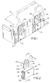
- Referring to the drawings in greater detail, and first to Fig. 1, the invention is embodied in a crimpable electrical terminal, generally designated 10, which is shown mounted to a wall 12 (Fig. 2) of a frame, generally designated 14 (Fig. 1), of a battery pack for a cellular or mobile telephone. The entire battery pack is not shown in the drawings, but
frame 14 is sufficient for a clear and concise understanding of the invention as embodied interminal 10. Two of the terminals are shown mounted to frame 14 in Fig. 1. Generally, each terminal 10 is adapted for terminating to a flatflexible circuit 16 shown in phantom. - The term "flat flexible circuit" is used herein in a generic sense to include conductors in conventional flexible flat cables and flexible circuitry of the type produced by etching or otherwise. Conductors of these types include flat conductors encased in an insulating film such as Mylar (polyethyleneterephthalate). Of course, it should be understood that the concepts of the invention herein for considerably reducing the dimensions of a crimpable electrical terminal are equally applicable for use with a wide variety of electrical conductors.
- Referring to Fig. 3 in conjunction with Figs. 1 and 2, each crimpable
electrical terminal 10 includes a contact portion, generally designated 20, at one end of the terminal, and a terminating portion, generally designated 22, at the opposite end of the terminal.Contact portion 20 and terminatingportion 22 form an elongated unitary structure which can be fabricated of stamped and formed sheet metal material. The contact and terminating portions generally define alongitudinal axis 24 of the terminal. -
Contact portion 20 is generally channel-shaped in cross-section generally transverse to terminatingportion 22 andlongitudinal axis 24 as seen best in Figs. 2 and 3. The channel-shaped portion includes abase 26 and a pair oflegs 28.Base 26 is generally flat (actually, slightly curved) to form acontact surface 30 which is engageable with a complementary contact within the telephone (not shown).Legs 28 are adapted for bending and clamping aboutwall 12 offrame 14. The legs are shown in phantom in Fig. 3 projecting rearwardly ofbase 26 in a straight configuration to allow the terminal to be mounted onto the front ofwall 12. When so mounted, the legs are bent toward each other as shown in full lines in Fig. 3 to embracewall 12 and securely mount the terminal to frame 14. - Terminating
portion 22 ofterminal 10 is generally U-shaped in cross-section and includes aweb 32, anelongated dimple 33, and a pair of side walls extending from the two opposite longitudinal edges of the web. The side walls are generally trapezoidally shaped with relativelywide base portions 34a, joined to the longitudinal edges ofweb 32, and relativelynarrow tips 34b which have beveled edges. It can be seen quite clearly in Fig. 3 that bases 34a ofsidewalls 34 are transversely aligned acrossweb 32, i.e. transversely oflongitudinal axis 24. This enables the terminating portion of the terminal to have as short a dimension as possible, i.e. in contrast to longitudinally offsetting the bases of the sidewalls. On the other hand,tips 34b ofsidewalls 34 are offset transversely of web 32 (i.e. longitudinally of axis 24) such that the tips are spaced longitudinally of the web. Therefore, the tips will bypass each other when crimped toward each other to terminateelectrical conductor 16. This allows for the terminating portion of the terminal to be as narrow as possible. - Fig. 4 shows sidewalls 34 of one of the
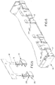
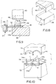
terminals 10 crimped ontoflat conductor cable 16. Arrows "A" indicate the crimped "height" of the terminatingportion 22 of the terminal. Fig. 4 also shows that a contact plating 36 can be applied to surface 30 ofbase 26 of thecontact portion 20 of the terminal. - Fig. 5 shows the terminal 10 after it is stamped and formed. The
carrier strip 18 which is manufactured with the terminal 10 is shown in phantom. The carrier strip is used to conveniently gang load the terminal on to wall 12 offrame 14. This carrier is severed from the terminal atcut 19 after the terminal is fully mounted tofram 14 withlegs 28 bent aroundwall 12. Fig. 6 shows theframe 14 without any terminals mounted to it. Fig. 7 is a more complete view offrame 14showing terminals 10 mounted thereon and the carrier strip already severed. An electrical device such as a battery (not shown) is held within this frame. Also shown onframe 14 are lockingledges 15 upon which a cover (not shown) may snap. - Figs. 8-10 show an
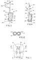
anvil 38 and apunch 40 of a type for crimping terminatingend 22 of one of theterminals 10.Anvil 38 includes atrough 42 into whichweb 32 of the terminal is positioned.Punch 40 includes a dual-radius forming surface 44 for engaging and crimpingsidewalls 34 of the terminal toward each other. - Fig. 9 shows one of the
terminals 10 mounted such that terminatingportion 22 is located betweenanvil 38 and punch 40, with theweb 32 resting on the anvil and sidewalls 34 projecting upwardly toward the punch. Thecontact portion 20 of the terminal would be positioned in an appropriate jig (not shown). In fact, the entire frame 14 (Fig. 1) can be placed into a jig after the terminals are mounted thereon, and the terminals can be crimped onto their respectiveflat conductor cables 16 simultaneously in a two-position press. - Fig. 10 shows an end view of the terminal positioned between
anvil 38 and punch 40 withsidewalls 34 projecting upwardly toward the punch. As the punch is moved downwardly toward the anvil in the direction of arrow "B", curved formingsurfaces 44 engagetips 34b of the sidewalls and bend or form the tips inwardly in the direction of arrows "C". Eventually, sidewalls 34 will be crimped or formed as shown in phantom in Fig. 10, withtips 34b of the sidewalls curved completely under and into engagement withflat conductor cable 16. - During the crimping operation,
tips 34b ofsidewalls 34 will be crimped or bent inwardly toward each other and bypass each other until the tips reach their eventual terminating positions against the flat conductor cable as shown in Fig. 10. If the tips were not offset longitudinally of the terminal as is contemplated by the present invention, the terminatingend 22 of the terminal, includingweb 32, would have to be made considerably wider as can be understood from the depiction of Fig. 10, in order for the tips of the sidewalls to move in an arcuate path into their eventual curved and crimped terminating positions. - It will be understood that the invention may be embodied in other specific forms without departing from the scope of the appended claims.
Claims (5)
- An electrical terminal (10) adapted for use with a flat conductor cable (16), the terminal having a terminating portion (22) and a contact portion (20) at one end of the terminating portion, the terminating portion with a generally U-shaped cross-section comprising a web (32) and a pair of sidewalls (34) extending from two opposite longitudinal edges of the web, the sidewalls being generally trapezoidally shaped with relatively wide bases (34a) and relatively narrow tips (34b), the bases (34a) being transversely aligned across the web (32), and the tips (34b) being offset across the web so as to be spaced longitudinally of the web, whereby the tips (34b) will bypass each other when crimped toward each other to terminate the flat conductor cable (16), the contact portion being generally channel-shaped in cross section generally transverse to the terminating portion comprising a generally flat contact surface with legs extending from the contact surface adapted to be fixed to a dielectric material.
- The electrical terminal of claim 1
wherein at least the terminating portion (22) of the terminal (10) is stamped and formed of sheet metal material. - The electrical terminal of claim 1,
including a contact portion (20) of the terminal at one end of the terminating portion (22). - The electrical terminal of claim 3
wherein said contact portion (20) is generally channel-shaped in cross-section generally transverse to the terminating portion (22). - The electrical terminal of claim 2
wherein the legs extending from the contact surface are bent around edges of the dielectric material.
Applications Claiming Priority (2)
| Application Number | Priority Date | Filing Date | Title |
|---|---|---|---|
| US572279 | 1995-12-13 | ||
| US08/572,279 US5634813A (en) | 1995-12-13 | 1995-12-13 | Crimpable electrical terminal |
Publications (3)
| Publication Number | Publication Date |
|---|---|
| EP0779677A2 EP0779677A2 (en) | 1997-06-18 |
| EP0779677A3 EP0779677A3 (en) | 1997-07-02 |
| EP0779677B1 true EP0779677B1 (en) | 2000-08-30 |
Family
ID=24287118
Family Applications (1)
| Application Number | Title | Priority Date | Filing Date |
|---|---|---|---|
| EP96119412A Expired - Lifetime EP0779677B1 (en) | 1995-12-13 | 1996-12-04 | Crimpable electrical terminal |
Country Status (4)
| Country | Link |
|---|---|
| US (1) | US5634813A (en) |
| EP (1) | EP0779677B1 (en) |
| JP (1) | JP2958865B2 (en) |
| DE (1) | DE69610063T2 (en) |
Families Citing this family (1)
| Publication number | Priority date | Publication date | Assignee | Title |
|---|---|---|---|---|
| US6364668B1 (en) | 2001-01-22 | 2002-04-02 | Molex Incorporated | Electrical connection system and method for flat circuits |
Family Cites Families (10)
| Publication number | Priority date | Publication date | Assignee | Title |
|---|---|---|---|---|
| DE1465328C3 (en) * | 1964-10-30 | 1975-06-12 | Bosch-Siemens-Hausgeraete Gmbh, 7000 Stuttgart | Flat angled device socket |
| US3395381A (en) * | 1966-11-25 | 1968-07-30 | Amp Inc | Crimpable connecting device for flat conductor cable |
| US3697925A (en) * | 1970-07-22 | 1972-10-10 | Amp Inc | Termination means for flat cable |
| BE789365A (en) * | 1971-09-30 | 1973-03-27 | Amp Inc | ELECTRICAL CONNECTOR |
| GB1474249A (en) * | 1974-01-09 | 1977-05-18 | Amp Inc | Electrical contact for flat conductor cable |
| US3933405A (en) * | 1974-05-16 | 1976-01-20 | General Motors Corporation | Electrical connector with deflectable butt contact terminal |
| FR2344979A1 (en) * | 1976-03-17 | 1977-10-14 | Amp Inc | INSULATION BOX FOR CONTACT TERMINAL |
| DE3011872A1 (en) * | 1980-03-27 | 1981-10-01 | Précision Mécanique Labinal S.A., 93403 Saint Quen, Seine-Saint-Denis | Female spade connector casing - has upper and lower inner abutments to resist removal of connector and which allow easy insertion |
| US4561714A (en) * | 1983-12-08 | 1985-12-31 | Bally Midway Mfg. Co. | Contact assembly for ribbon cable |
| US5078617A (en) * | 1991-01-25 | 1992-01-07 | Molex Incorporated | Piercing insulation displacement board terminal |
-
1995
- 1995-12-13 US US08/572,279 patent/US5634813A/en not_active Expired - Fee Related
-
1996
- 1996-12-04 EP EP96119412A patent/EP0779677B1/en not_active Expired - Lifetime
- 1996-12-04 DE DE69610063T patent/DE69610063T2/en not_active Expired - Fee Related
- 1996-12-11 JP JP8351909A patent/JP2958865B2/en not_active Expired - Lifetime
Also Published As
| Publication number | Publication date |
|---|---|
| EP0779677A2 (en) | 1997-06-18 |
| DE69610063T2 (en) | 2001-05-10 |
| JPH09180773A (en) | 1997-07-11 |
| JP2958865B2 (en) | 1999-10-06 |
| DE69610063D1 (en) | 2000-10-05 |
| US5634813A (en) | 1997-06-03 |
| EP0779677A3 (en) | 1997-07-02 |
Similar Documents
| Publication | Publication Date | Title |
|---|---|---|
| US4159158A (en) | Displation connector having improved terminal supporting means | |
| US5964620A (en) | Insulation displacement connector | |
| US5788539A (en) | Surface mountable electrical connector | |
| US3881796A (en) | Terminal for flat conductor | |
| EP0112144B1 (en) | Electrical connector for flat flexible cable | |
| JP3097895B2 (en) | Electrical connector | |
| US20060128204A1 (en) | Electric connector | |
| US5716230A (en) | Surface engageable electrical connector | |
| EP0795930B1 (en) | High contact force pin-receiving electrical contact | |
| JP3463900B2 (en) | Electrical connector and method of manufacturing the same | |
| EP0718918B1 (en) | Connector with spring contact member and shorting means | |
| EP1139492B1 (en) | A method for connecting a terminal fitting and a flat conductor and a terminal connection apparatus | |
| US5554046A (en) | Solderless terminal | |
| EP0779677B1 (en) | Crimpable electrical terminal | |
| US6033255A (en) | Press-connecting terminal | |
| US5697813A (en) | Connection terminal | |
| US5246381A (en) | Electrical terminal for modulator connector | |
| US4540224A (en) | Grounding clip for use with shielded, jacketed flat cable | |
| US5591044A (en) | Press-connecting terminal | |
| JP2988608B2 (en) | Female terminal and method of manufacturing the same | |
| EP0600402B1 (en) | Electrical connector with improved terminal retention | |
| EP0718919A1 (en) | Connector with spring contact member and shorting means | |
| GB1585345A (en) | Electrical connector having displaceable sidewall terminal element | |
| US6283784B1 (en) | Press-contact terminal fitting | |
| US4533206A (en) | Flexible printed circuit connector |
Legal Events
| Date | Code | Title | Description |
|---|---|---|---|
| PUAI | Public reference made under article 153(3) epc to a published international application that has entered the european phase |
Free format text: ORIGINAL CODE: 0009012 |
|
| PUAL | Search report despatched |
Free format text: ORIGINAL CODE: 0009013 |
|
| AK | Designated contracting states |
Kind code of ref document: A2 Designated state(s): DE FR GB IT |
|
| RHK1 | Main classification (correction) |
Ipc: H01R 9/07 |
|
| AK | Designated contracting states |
Kind code of ref document: A3 Designated state(s): DE FR GB IT |
|
| 17P | Request for examination filed |
Effective date: 19971206 |
|
| GRAG | Despatch of communication of intention to grant |
Free format text: ORIGINAL CODE: EPIDOS AGRA |
|
| 17Q | First examination report despatched |
Effective date: 20000105 |
|
| GRAG | Despatch of communication of intention to grant |
Free format text: ORIGINAL CODE: EPIDOS AGRA |
|
| GRAH | Despatch of communication of intention to grant a patent |
Free format text: ORIGINAL CODE: EPIDOS IGRA |
|
| ITF | It: translation for a ep patent filed |
Owner name: DE DOMINICIS & MAYER S.R.L. |
|
| RIC1 | Information provided on ipc code assigned before grant |
Free format text: 7H 01R 12/08 A, 7H 01R 12/38 B, 7H 01R 13/40 B, 7H 01R 13/42 B |
|
| GRAH | Despatch of communication of intention to grant a patent |
Free format text: ORIGINAL CODE: EPIDOS IGRA |
|
| GRAA | (expected) grant |
Free format text: ORIGINAL CODE: 0009210 |
|
| AK | Designated contracting states |
Kind code of ref document: B1 Designated state(s): DE FR GB IT |
|
| REF | Corresponds to: |
Ref document number: 69610063 Country of ref document: DE Date of ref document: 20001005 |
|
| PGFP | Annual fee paid to national office [announced via postgrant information from national office to epo] |
Ref country code: GB Payment date: 20001107 Year of fee payment: 5 |
|
| ET | Fr: translation filed | ||
| PGFP | Annual fee paid to national office [announced via postgrant information from national office to epo] |
Ref country code: FR Payment date: 20001204 Year of fee payment: 5 |
|
| PGFP | Annual fee paid to national office [announced via postgrant information from national office to epo] |
Ref country code: DE Payment date: 20001222 Year of fee payment: 5 |
|
| PLBE | No opposition filed within time limit |
Free format text: ORIGINAL CODE: 0009261 |
|
| STAA | Information on the status of an ep patent application or granted ep patent |
Free format text: STATUS: NO OPPOSITION FILED WITHIN TIME LIMIT |
|
| 26N | No opposition filed | ||
| PG25 | Lapsed in a contracting state [announced via postgrant information from national office to epo] |
Ref country code: GB Free format text: LAPSE BECAUSE OF NON-PAYMENT OF DUE FEES Effective date: 20011204 |
|
| REG | Reference to a national code |
Ref country code: GB Ref legal event code: IF02 |
|
| PG25 | Lapsed in a contracting state [announced via postgrant information from national office to epo] |
Ref country code: DE Free format text: LAPSE BECAUSE OF NON-PAYMENT OF DUE FEES Effective date: 20020702 |
|
| GBPC | Gb: european patent ceased through non-payment of renewal fee |
Effective date: 20011204 |
|
| PG25 | Lapsed in a contracting state [announced via postgrant information from national office to epo] |
Ref country code: FR Free format text: LAPSE BECAUSE OF NON-PAYMENT OF DUE FEES Effective date: 20020830 |
|
| REG | Reference to a national code |
Ref country code: FR Ref legal event code: ST |
|
| PG25 | Lapsed in a contracting state [announced via postgrant information from national office to epo] |
Ref country code: IT Free format text: LAPSE BECAUSE OF NON-PAYMENT OF DUE FEES;WARNING: LAPSES OF ITALIAN PATENTS WITH EFFECTIVE DATE BEFORE 2007 MAY HAVE OCCURRED AT ANY TIME BEFORE 2007. THE CORRECT EFFECTIVE DATE MAY BE DIFFERENT FROM THE ONE RECORDED. Effective date: 20051204 |