EP0779535B1 - Camera with variable deflection - Google Patents
Camera with variable deflection Download PDFInfo
- Publication number
- EP0779535B1 EP0779535B1 EP96119278A EP96119278A EP0779535B1 EP 0779535 B1 EP0779535 B1 EP 0779535B1 EP 96119278 A EP96119278 A EP 96119278A EP 96119278 A EP96119278 A EP 96119278A EP 0779535 B1 EP0779535 B1 EP 0779535B1
- Authority
- EP
- European Patent Office
- Prior art keywords
- camera
- lens system
- cameras
- objective lens
- stereoscopic
- Prior art date
- Legal status (The legal status is an assumption and is not a legal conclusion. Google has not performed a legal analysis and makes no representation as to the accuracy of the status listed.)
- Expired - Lifetime
Links
Images
Classifications
-
- G—PHYSICS
- G03—PHOTOGRAPHY; CINEMATOGRAPHY; ANALOGOUS TECHNIQUES USING WAVES OTHER THAN OPTICAL WAVES; ELECTROGRAPHY; HOLOGRAPHY
- G03B—APPARATUS OR ARRANGEMENTS FOR TAKING PHOTOGRAPHS OR FOR PROJECTING OR VIEWING THEM; APPARATUS OR ARRANGEMENTS EMPLOYING ANALOGOUS TECHNIQUES USING WAVES OTHER THAN OPTICAL WAVES; ACCESSORIES THEREFOR
- G03B35/00—Stereoscopic photography
- G03B35/08—Stereoscopic photography by simultaneous recording
-
- G—PHYSICS
- G03—PHOTOGRAPHY; CINEMATOGRAPHY; ANALOGOUS TECHNIQUES USING WAVES OTHER THAN OPTICAL WAVES; ELECTROGRAPHY; HOLOGRAPHY
- G03B—APPARATUS OR ARRANGEMENTS FOR TAKING PHOTOGRAPHS OR FOR PROJECTING OR VIEWING THEM; APPARATUS OR ARRANGEMENTS EMPLOYING ANALOGOUS TECHNIQUES USING WAVES OTHER THAN OPTICAL WAVES; ACCESSORIES THEREFOR
- G03B35/00—Stereoscopic photography
-
- H—ELECTRICITY
- H04—ELECTRIC COMMUNICATION TECHNIQUE
- H04N—PICTORIAL COMMUNICATION, e.g. TELEVISION
- H04N13/00—Stereoscopic video systems; Multi-view video systems; Details thereof
- H04N13/20—Image signal generators
- H04N13/204—Image signal generators using stereoscopic image cameras
- H04N13/239—Image signal generators using stereoscopic image cameras using two 2D image sensors having a relative position equal to or related to the interocular distance
-
- H—ELECTRICITY
- H04—ELECTRIC COMMUNICATION TECHNIQUE
- H04N—PICTORIAL COMMUNICATION, e.g. TELEVISION
- H04N13/00—Stereoscopic video systems; Multi-view video systems; Details thereof
- H04N13/20—Image signal generators
- H04N13/204—Image signal generators using stereoscopic image cameras
- H04N13/243—Image signal generators using stereoscopic image cameras using three or more 2D image sensors
-
- H—ELECTRICITY
- H04—ELECTRIC COMMUNICATION TECHNIQUE
- H04N—PICTORIAL COMMUNICATION, e.g. TELEVISION
- H04N13/00—Stereoscopic video systems; Multi-view video systems; Details thereof
- H04N13/20—Image signal generators
- H04N13/296—Synchronisation thereof; Control thereof
-
- H—ELECTRICITY
- H04—ELECTRIC COMMUNICATION TECHNIQUE
- H04N—PICTORIAL COMMUNICATION, e.g. TELEVISION
- H04N23/00—Cameras or camera modules comprising electronic image sensors; Control thereof
- H04N23/58—Means for changing the camera field of view without moving the camera body, e.g. nutating or panning of optics or image sensors
-
- H—ELECTRICITY
- H04—ELECTRIC COMMUNICATION TECHNIQUE
- H04N—PICTORIAL COMMUNICATION, e.g. TELEVISION
- H04N13/00—Stereoscopic video systems; Multi-view video systems; Details thereof
- H04N2013/0074—Stereoscopic image analysis
- H04N2013/0081—Depth or disparity estimation from stereoscopic image signals
Definitions
- the present invention relates to a camera with variable deflection and to a stereoscopic camera system using such cameras.
- Known cameras used in stereoscopic applications do not differ in principle from normal cameras and comprise an objective lens system, which receives the light emitted from a target object, and an intermediate optic system, which forms the light beam into an appropriate shape for the following image device, which creates pixel signals and is formed by an electronic image device.
- Known stereoscopic camera systems use two or more different angle images.
- two or more cameras depending on the number of images required, have to be used.
- each camera forms special convergence angles with each of the other cameras.
- the number of cameras is chosen as two.
- the only convergence angle is the angle formed by the two cameras focused on the target object.
- the convergence angle is related to the viewing position of the observer. If, for example, the target moves, the two cameras must be focused onto the moving target under the condition that the convergence angle has to be kept in an appropriate range.
- FR 2 699 296 shows a camera system for the generation of stereoscopic images using two single cameras, wherein the distance of the camera and their convergence angle can be changed automatically as function of the distance of the target object.
- the cameras are moved and rotated as a whole by motor means on a supplying arm to change the convergence angle.
- a vari-angle prism is an electro-optically induced deflection device.
- Such kind of devices are described e.g. in the articles "A Planar Electrooptic-Prism Switch”, from I. P. Kaminow et al.; IEEE Journal of Quantum Electronics, August 1975 and ""Electro-optically induced deflection in liquid-crystal waveguides", J. P. Sheridan et al; Journal of Applied Physics, Vol. 45, No 12, December 1974.
- the known camera systems show the above mentioned disadvantages, i.e. it is not easy to change the convergence angle rapidly as the distance between the cameras and the target changes.
- the present invention relates to a camera with an objective lens system, an intermediate lens system, which forms the incident light beam, and an image device wherein a controllable light deflecting device is located between the objective lens system and the intermediate lens system.
- Such a controllable light deflecting device of the camera can be any device, which allows the controllable deflection of an incident light beam, like for example an electro-optical device, such as a vari-angle prism or a vari-angle plate.
- the image device can be formed by an electronically image device for creating pixel signals.
- the objective lens system is rotatable by a rotation mechanism.
- the combination of a rotable objective lens and a controllable light deflecting device has the advantage, that a very wide range of convergence angles can be covered, but it is not necessary to rotate the whole camera. Instead it is sufficient just to rotate the objective lens. Therefore, smaller motors can be used.
- Both the rotation mechanism and the controllable light deflecting device can be controlled with the help of a common convergence angle signal.
- the invention relates to a camera system using at least two of the above described cameras which can be focused at a target object and include controllable light deflecting devices, wherein the convergence angle between each two of the cameras and the object can be controlled.
- At least one of said cameras can be provided with a moving mechanism for manually or automatic control.
- each camera can be provided with a focus controller for controlling the optics of the camera.
- rotation mechanism controllers and the controllers of the light deflection devices are controlled by a common convergence angle signal, which can be supplied by, for example, a conventional sensor which measures the distance between the camera and said target object.
- controllers of the camera system according to the invention are controlled by a distance signal.
- This distance signal is converted by a signal converter into a convergence angle signal used for the vari-angle prism controllers and the rotation mechanism controllers.
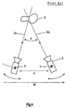
- Fig. 4 shows a stereoscopic camera system according to the prior art, wherein two cameras 1, 2 are focused onto a target object 3, so that a convergence angle 4 is enclosed between an optical axis LA of the left camera and an optical axis RA of the right camera 2.
- Both cameras 1, 2 can be independently rotated around a respective centre of rotation 5, 6. Further the cameras can be moved, e.g. such that the distance d between them is varied and/or as the whole camera sytem is moved in any direction, indicated by arrow M for one coordinate. As it is clear from Fig. 4, the cameras are moved and rotated as a whole in respect to their optical axes.
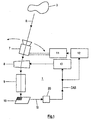
- Fig. 1 shows a preferred embodiment according to the present invention, which is a camera, wherein an objective lens system 7 captures the incident light rays R from a target object 3.
- This objective lens system 7 is rotatable by a rotation mechanism 11, which is controlled by a controller 12.
- the light from the objective lens system 7 passes through a vari-angle prism 8, wherein the deflection angle can be controlled.
- Such vari-angle prisms are known in the art.
- the light passes through an intermediate bus system 9 which can be viewed as a beam forming optics, and is incident onto an image device 10, which is usually an electronic image device.
- the deflection angle of the vari-angle prism 8 is controlled as a function of a convergence angle signal CAS by a controller 13.
- the signal CAS is determined by detecting means 20, which get input signals IS from said image device 10.
- Signals IS are a mass for the position of object 3 in relation to the direction of the whole camera 1.
- a closed loop control of signal CAS can be realsied.
- Such means may work with electromagnetical, optical and/or acoustical ray detection and may include as well receiving means as transmitting means for said rays.
- deflection angle controllable device 8 it is not necessary to rotate the whole camera, instead it is only necessary to rotate the objective lens system 7 so that the necessary motors (not shown) can be of a smaller size.
- the embodiment is not restricted to the use of a vari-angle prism 8, but every electronical and/or optical controllable device capable of controlling the deflection of a light beam can be used.
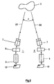
- Fig. 2 shows the basic illustration of a stereoscopic camera system using two cameras according to Fig. 1.
- the left camera 1 having objective lens system 7 captures the incident light rays LR from a target object 3.
- the right camera 2 is symmetrical to the left camera 1 and receives rays RR and includes also an objectice lens 7, a vari-angle prism 8, a intermediate bus system 9, and an image device 10.
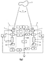
- FIG. 3 shows more detailed schematics of a embodiment of a stereo camera system. Means having same functions as in the preceding figures are marked with the same reference numbers.
- the two cameras 1, 2 are formed by cameras according to Fig. 1, each comprising an objective lens system 7, a vari-angle prism 8, an intermediate lens system 9 and an image device 10.
- the rotation of the objective lens system 7 of each camera 1, 2 is controlled by a respective rotation mechanism 11, together with controllers 12.
- the deflection angles of the vari-angle prisms 8 are controlled by controllers 13.
- Both cameras 1, 2 can be moved independent from each other by a respective moving mechanism 14 controlled by a controller 15, respectively.
- each camera 1, 2 is controlled by a focus controller 16 provided for each camera 1, 2. Both focus controllers 16 are controlled by a distance signal DS of the distance between the cameras and the target object 3 which is measured appropriately. This distance signal DS is also used to control the moving mechanisms 14 by the controllers 15. With a signal converter 17 this distance signal DS is converted into a convergence angle signal CAS, which is necessary for the rotation and the deflection angle controllers 12, 13.
- the signal DS is determined e.g. by not shown detecting means, which get input signals from said image devices 10, by a manual-input signal from a camera operator, or thelike. These input signals are a mass for the position of object 3 in relation to the direction of the whole camera 1. As said input signal depends also on control parameters for rotation mechanism 11 and prism 8, a closed loop control of said input signals and of signal CAS can be realsied.
- detecting means which detect the distance between camera system 1, 2 and object 3.
- Such means are well known for focus-control and may work with electromagnetical, optical and/or acoustical ray detection and may include as well receiving means as transmitting means for said rays.
- the present invention it is possible for a wide range of possible values of the convergence angle and the target object distance, to keep the intermediate optics 9, i.e. the whole camera, fixed.
- the deflection angle of the vari-angle prism 8 it is only necessary that the objective lens optics 7 of the cameras 1, 2 is rotated.
- the stereoscopic camera system is not limited to the use of two cameras. According to the application it is possible to use more than two cameras.
Landscapes
- Engineering & Computer Science (AREA)
- Multimedia (AREA)
- Signal Processing (AREA)
- Physics & Mathematics (AREA)
- General Physics & Mathematics (AREA)
- Stereoscopic And Panoramic Photography (AREA)
- Testing, Inspecting, Measuring Of Stereoscopic Televisions And Televisions (AREA)
- Mechanical Light Control Or Optical Switches (AREA)
Description
- D:
- distance between camera system and target object;
- d:
- distance between said two cameras of the camera system.
- Fig. 1
- shows a basic embodiment of a camera according to the invention;
- Fig. 2
- shows a first embodiment of a stereoscopic camera system using cameras according to the embodiment of Fig. 1;
- Fig. 3
- shows a second embodiment of a stereoscopic camera system;
- Fig. 4
- shows a diagram of a prior stereoscopic camera system.
Claims (8)
- A camera (1, 2) comprising:a rotatable objective lens system (7);an intermediate lens system (9);a controllable light deflecting device (8) located between the objective lens system (7) and the intermediate lens system (9);an imager device (10) which receives images from said intermediate lens system, and produces an image signal (IS); andcircuitry (20, 12, 13) responsive to said image signal (IS) for generating a convergence angle signal (CAS) responsive to an imaged object for controlling said controllable light deflecting device (8) and said rotatable objective lens system, said image signal depending on relative position between said camera (1, 2) and a target object (3).
- Camera according to claim 1 characterized in that the controllable light deflecting device (8) is an electro-optical device, such as a variangle prism or a variangle plate.
- Camera according to claim 1 characterized in that it comprises rotating means (11) for rotating said rotatable lens system and wherein said circuitry responsive to said image signal (IS) includes means (12, 13) for controlling said rotating means (11) and said light deflecting device (8).
- A stereoscopic camera system, comprising:a plurality of cameras, each said camera (1, 2) capable of focusing at a target object (3) wherein a convergence angle between two of said cameras and the object can be controlled, each said camera being a camera according to one of the preciding claims.
- The stereoscopic camera system according to claim 4, characterized in that it comprises respective rotating means for rotating the respective rotatable objective lens system of each camera and wherein said respective rotating means and said respective deflecting devices are controlled responsive to a common convergence angle signal (GAS).
- The stereoscopic camera system according to claim 4, characterized in that at least one of said camera (1, 2) is provided with a moving mechanism (14) for moving said camera independently from the other one.
- The stereoscopic camera system according to claims 4 to 6, characterized in that each camera (1, 2) is provided with a focus controller (16) for controlling the optics of the camera (1, 2).
- The stereoscopic camera system according to claims 4 to 7, characterized in that all controllers (12, 13, 16) of the system are controlled in dependance function of a distance signal (DS).
Applications Claiming Priority (2)
| Application Number | Priority Date | Filing Date | Title |
|---|---|---|---|
| GB9525309A GB2308199A (en) | 1995-12-11 | 1995-12-11 | Camera with variable deflection |
| GB9525309 | 1995-12-11 |
Publications (2)
| Publication Number | Publication Date |
|---|---|
| EP0779535A1 EP0779535A1 (en) | 1997-06-18 |
| EP0779535B1 true EP0779535B1 (en) | 2003-06-25 |
Family
ID=10785253
Family Applications (1)
| Application Number | Title | Priority Date | Filing Date |
|---|---|---|---|
| EP96119278A Expired - Lifetime EP0779535B1 (en) | 1995-12-11 | 1996-12-02 | Camera with variable deflection |
Country Status (5)
| Country | Link |
|---|---|
| EP (1) | EP0779535B1 (en) |
| JP (1) | JP3806198B2 (en) |
| KR (1) | KR100450917B1 (en) |
| DE (1) | DE69628806T2 (en) |
| GB (1) | GB2308199A (en) |
Cited By (1)
| Publication number | Priority date | Publication date | Assignee | Title |
|---|---|---|---|---|
| WO2009014416A1 (en) * | 2007-07-20 | 2009-01-29 | Mimos Berhad | Setup for three dimensional image capture |
Families Citing this family (9)
| Publication number | Priority date | Publication date | Assignee | Title |
|---|---|---|---|---|
| DE19836681B4 (en) * | 1997-09-19 | 2008-03-27 | Carl Zeiss Ag | Stereoscopic recording and playback system |
| DE19956266A1 (en) * | 1999-11-23 | 2001-06-21 | Schuetz Dich Entwicklungs & Ve | Monitoring system |
| DE10250659A1 (en) * | 2002-10-31 | 2004-05-13 | Valeo Schalter Und Sensoren Gmbh | Monitoring device and dome control module |
| WO2006095274A1 (en) * | 2005-02-02 | 2006-09-14 | Koninklijke Philips Electronics N.V. | Camera pair using fluid based lenses |
| IT1393775B1 (en) * | 2009-04-03 | 2012-05-08 | Univ Degli Studi Torino | STEREOSCOPIC RECOVERY SYSTEM |
| DE102011010012A1 (en) * | 2011-02-02 | 2012-08-02 | Conti Temic Microelectronic Gmbh | Optical device with electro-optical medium |
| DE102011112726A1 (en) * | 2011-09-07 | 2013-03-07 | 3Ality Digital Systems, Llc | Method for controlling rig of camera for recording three-dimensional film, involves automatically pivoting cameras apart about an axis passing via camera vertical axis if background disparity of recorded image is more than critical value |
| DE102011016171B4 (en) * | 2011-04-05 | 2012-12-27 | 3Ality Digital Systems, Llc | Method of Aligning a 3D Camera and Method of Controlling a 3D Camera While Filming |
| CN110213470A (en) * | 2019-06-25 | 2019-09-06 | 深圳市永顺创能技术有限公司 | Camera apparatus with upper and lower shooting function |
Family Cites Families (13)
| Publication number | Priority date | Publication date | Assignee | Title |
|---|---|---|---|---|
| US4114171A (en) * | 1976-04-06 | 1978-09-12 | Vivitar Corporation | Reflex camera with internal zoom lens |
| CH598616A5 (en) * | 1976-06-24 | 1978-05-12 | Lexie Real Estate Ets | |
| US4464028A (en) * | 1981-11-17 | 1984-08-07 | Condon Chris J | Motion picture system for single strip 3-D filming |
| JPS59501964A (en) * | 1982-08-09 | 1984-11-22 | キスゼミ・イノヴエシオス・イロダ | Method for recording and reproducing visual information for three-dimensional reproduction, and apparatus for recording and reproducing three-dimensional images |
| US4437745A (en) * | 1982-09-30 | 1984-03-20 | Stephen Hajnal | Three dimensional camera system |
| FR2616923B1 (en) * | 1987-06-17 | 1990-06-08 | Drouard Gabriel | MODULAR DEVICE FOR STEREOSCOPIC VIEWING |
| JPH0193983A (en) * | 1987-10-05 | 1989-04-12 | Sharp Corp | Automatic convergence angle adjusting type stereoscopic camera |
| JPH0193984A (en) * | 1987-10-05 | 1989-04-12 | Sharp Corp | Automatic adjusting mechanism for stereoscopic camera convergence angle |
| JPH0193727A (en) * | 1987-10-05 | 1989-04-12 | Sharp Corp | Stereoscopic image pickup camera of convergence angle automatically following type |
| JP2775878B2 (en) * | 1989-07-26 | 1998-07-16 | キヤノン株式会社 | Anti-vibration imaging device |
| WO1991009343A1 (en) * | 1989-12-18 | 1991-06-27 | Lezy Jean Pierre | Method and devices for recording images which are visible in three dimensions, and uses of said method |
| FR2699296B1 (en) | 1992-12-14 | 1994-12-30 | Olivier Boute | Device for triscopic shots. |
| JPH06308427A (en) * | 1993-04-26 | 1994-11-04 | Canon Inc | Stereoscopic image forming device |
-
1995
- 1995-12-11 GB GB9525309A patent/GB2308199A/en not_active Withdrawn
-
1996
- 1996-11-28 JP JP31791396A patent/JP3806198B2/en not_active Expired - Fee Related
- 1996-12-02 EP EP96119278A patent/EP0779535B1/en not_active Expired - Lifetime
- 1996-12-02 DE DE69628806T patent/DE69628806T2/en not_active Expired - Lifetime
- 1996-12-09 KR KR1019960062965A patent/KR100450917B1/en not_active IP Right Cessation
Cited By (1)
| Publication number | Priority date | Publication date | Assignee | Title |
|---|---|---|---|---|
| WO2009014416A1 (en) * | 2007-07-20 | 2009-01-29 | Mimos Berhad | Setup for three dimensional image capture |
Also Published As
| Publication number | Publication date |
|---|---|
| DE69628806T2 (en) | 2004-04-15 |
| KR100450917B1 (en) | 2004-12-29 |
| GB9525309D0 (en) | 1996-02-07 |
| JP3806198B2 (en) | 2006-08-09 |
| KR970048902A (en) | 1997-07-29 |
| GB2308199A (en) | 1997-06-18 |
| DE69628806D1 (en) | 2003-07-31 |
| EP0779535A1 (en) | 1997-06-18 |
| JPH09185139A (en) | 1997-07-15 |
Similar Documents
| Publication | Publication Date | Title |
|---|---|---|
| US5003385A (en) | Stereoscopic television system | |
| US5142642A (en) | Stereoscopic television system | |
| US5448395A (en) | Non-mechanical step scanner for electro-optical sensors | |
| US5937212A (en) | Image pickup apparatus | |
| US4288819A (en) | Multi-field imaging device | |
| US5727239A (en) | Photographing optical apparatus | |
| EP0779535B1 (en) | Camera with variable deflection | |
| KR20000035957A (en) | Viewing apparatus | |
| US6112033A (en) | Multiple-lens image pickup apparatus for viewing in stereoscopic panoramic, and ordinary photographing modes | |
| US5107117A (en) | Optoelectronic viewing system | |
| KR100220888B1 (en) | Method for providing multiview 3-dimensional images using aperture and system therefor | |
| US6020993A (en) | 3-D photo attachment for a 2-D light microscope | |
| US20010010565A1 (en) | Three dimensional display apparatus of the integral photography type | |
| US20030164841A1 (en) | System and method for passive three-dimensional data acquisition | |
| US4509832A (en) | Optical arrangement for producing two anamorphotically compressed images correlated by an interocular base distance | |
| JP3064992B2 (en) | Stereoscopic image display method and device | |
| JPH07255006A (en) | Scanning light beam valve sensor system | |
| JP2864561B2 (en) | Scanning imaging device | |
| US20050185274A1 (en) | Method and arrangement for stereoscopic viewing | |
| US5438386A (en) | Coaxial master-slave lens photographing apparatus | |
| JPH0678337A (en) | Stereoscopic image pickup device | |
| JPH08220448A (en) | Stereoscopic vision adapter for endoscope | |
| JPH07209573A (en) | 3-d vision camera | |
| JPS62266535A (en) | Stereoscopic image pickup device | |
| JPH095642A (en) | Stereoscopic endoscope device |
Legal Events
| Date | Code | Title | Description |
|---|---|---|---|
| PUAI | Public reference made under article 153(3) epc to a published international application that has entered the european phase |
Free format text: ORIGINAL CODE: 0009012 |
|
| AK | Designated contracting states |
Kind code of ref document: A1 Designated state(s): DE FR GB IT |
|
| 17P | Request for examination filed |
Effective date: 19971211 |
|
| RAP1 | Party data changed (applicant data changed or rights of an application transferred) |
Owner name: THOMSON MULTIMEDIA |
|
| 17Q | First examination report despatched |
Effective date: 20020522 |
|
| GRAH | Despatch of communication of intention to grant a patent |
Free format text: ORIGINAL CODE: EPIDOS IGRA |
|
| GRAH | Despatch of communication of intention to grant a patent |
Free format text: ORIGINAL CODE: EPIDOS IGRA |
|
| GRAA | (expected) grant |
Free format text: ORIGINAL CODE: 0009210 |
|
| AK | Designated contracting states |
Designated state(s): DE FR GB IT |
|
| REG | Reference to a national code |
Ref country code: GB Ref legal event code: FG4D |
|
| REF | Corresponds to: |
Ref document number: 69628806 Country of ref document: DE Date of ref document: 20030731 Kind code of ref document: P |
|
| ET | Fr: translation filed | ||
| PLBE | No opposition filed within time limit |
Free format text: ORIGINAL CODE: 0009261 |
|
| STAA | Information on the status of an ep patent application or granted ep patent |
Free format text: STATUS: NO OPPOSITION FILED WITHIN TIME LIMIT |
|
| 26N | No opposition filed |
Effective date: 20040326 |
|
| PGFP | Annual fee paid to national office [announced via postgrant information from national office to epo] |
Ref country code: GB Payment date: 20121219 Year of fee payment: 17 Ref country code: IT Payment date: 20121220 Year of fee payment: 17 |
|
| PGFP | Annual fee paid to national office [announced via postgrant information from national office to epo] |
Ref country code: DE Payment date: 20121217 Year of fee payment: 17 Ref country code: FR Payment date: 20130128 Year of fee payment: 17 |
|
| REG | Reference to a national code |
Ref country code: DE Ref legal event code: R119 Ref document number: 69628806 Country of ref document: DE |
|
| GBPC | Gb: european patent ceased through non-payment of renewal fee |
Effective date: 20131202 |
|
| REG | Reference to a national code |
Ref country code: FR Ref legal event code: ST Effective date: 20140829 |
|
| REG | Reference to a national code |
Ref country code: DE Ref legal event code: R119 Ref document number: 69628806 Country of ref document: DE Effective date: 20140701 |
|
| PG25 | Lapsed in a contracting state [announced via postgrant information from national office to epo] |
Ref country code: DE Free format text: LAPSE BECAUSE OF NON-PAYMENT OF DUE FEES Effective date: 20140701 |
|
| PG25 | Lapsed in a contracting state [announced via postgrant information from national office to epo] |
Ref country code: FR Free format text: LAPSE BECAUSE OF NON-PAYMENT OF DUE FEES Effective date: 20131231 Ref country code: GB Free format text: LAPSE BECAUSE OF NON-PAYMENT OF DUE FEES Effective date: 20131202 |
|
| PG25 | Lapsed in a contracting state [announced via postgrant information from national office to epo] |
Ref country code: IT Free format text: LAPSE BECAUSE OF NON-PAYMENT OF DUE FEES Effective date: 20131231 |
|
| PG25 | Lapsed in a contracting state [announced via postgrant information from national office to epo] |
Ref country code: IT Free format text: LAPSE BECAUSE OF NON-PAYMENT OF DUE FEES Effective date: 20131202 |