EP0779006B1 - Television tuning systems and methods to produce a ghost-free television signal - Google Patents
Television tuning systems and methods to produce a ghost-free television signal Download PDFInfo
- Publication number
- EP0779006B1 EP0779006B1 EP96916274A EP96916274A EP0779006B1 EP 0779006 B1 EP0779006 B1 EP 0779006B1 EP 96916274 A EP96916274 A EP 96916274A EP 96916274 A EP96916274 A EP 96916274A EP 0779006 B1 EP0779006 B1 EP 0779006B1
- Authority
- EP
- European Patent Office
- Prior art keywords
- ghost
- television signal
- antenna
- television
- ghost cancellation
- Prior art date
- Legal status (The legal status is an assumption and is not a legal conclusion. Google has not performed a legal analysis and makes no representation as to the accuracy of the status listed.)
- Expired - Lifetime
Links
Images

Classifications
-
- H—ELECTRICITY
- H04—ELECTRIC COMMUNICATION TECHNIQUE
- H04N—PICTORIAL COMMUNICATION, e.g. TELEVISION
- H04N5/00—Details of television systems
- H04N5/14—Picture signal circuitry for video frequency region
- H04N5/21—Circuitry for suppressing or minimising disturbance, e.g. moiré or halo
- H04N5/211—Ghost signal cancellation
Definitions
- the invention relates to a television system and a method for receiving a television signal.
- the invention is in particular useful to television systems and methods to produce a television signal from which images which are substantially ghost-free can be obtained.
- Such reflected signals have different delay times and amplitudes than the transmitted original television signal, causing the images which are displayed on a television display from a received television signal (which has been interfered with and altered) to have superimposed copies thereof, i.e., ghosts.
- These ghosts are classified as pre-ghosts and post-ghosts depending on whether the signals of the received television signal which produce them are received before or after the main signal of the received television signal which corresponds substantially to the transmitted original television signal.
- the position or phase of an antenna is hereafter referred to as the "directionality" of the antenna, and rotating the position or adjusting the phase of an antenna is hereinafter referred to as “changing the directionality” of the antenna.
- directionality The position or phase of an antenna
- changing the directionality the antenna directionality change approach
- a viewer changes the directionality of an antenna until reception of ghosts is minimized and/or reception of the main signal is maximized. In general, this is a trial and error procedure which often only minimizes, rather than solves, the ghosting problem.
- each time the directionality of the antenna is changed it may be necessary for a tuner which is used in the process of obtaining images, from a television signal received by the television for a selected channel, on a television display to change its tuning frequency. (It is noted that each channel has a different television signal associated with it.) Still further, since the characteristics of a transmission path varies from channel to channel, changing the directionality of the antenna is usually necessary whenever a different channel is selected by a the viewer.
- JP-A-58-115902 discloses a TV reception antenna system stores the directivity of an antenna when a ghost detection circuit detects that a ghost component in a video signal is minimized.
- the antenna is controlled automatically to attain the stored directivity.
- US-A-4,542,326 discloses a microprocessor-controlled antenna positing system for automatically steering a rotatable antenna in the direction of a source of radiated signals.
- the system seeks the best signal when a new channel or frequency is selected, remembers that preferred antenna position, and will return to it whenever that channel or frequency is subsequently selected.
- the selected antenna heading may be modified to avoid TV ghosts.
- This second approach involves performing a ghost cancellation operation on a television signal after it has been received and demodulated, i.e., at baseband.
- a transmission channel is characterized (at least those parameters which contribute to signal interference and alteration) by transmitting a ghost cancellation reference signal (hereinafter referred to as a "GCR signal") having known characteristics over the transmission channel as part of a television signal.
- GCR signal ghost cancellation reference signal
- both the television signal and the GCR signal are subjected to the characteristics of the transmission channel.
- the received GCR signal (as altered by the channel characteristics) is compared to the original GCR signal, and filter coefficients reflecting the differences between the original and received GCR signals are calculated.
- These coefficients hereinafter referred to as “ghost cancellation coefficients" are provided to digital IIR and/or FIR filters in order to model an inverse of the channel characteristics.
- JP-A-58-121877 which is considered to be the closest prior art, discloses a ghost detection circuit determining tap gain settings for a transversal filter processing the TV signal.
- the tap gain settings are stored in a memory to eliminate a ghost signal just after channel switching.
- test signal is transmitted over a communication channel and the signal is received by a receiver.
- the temporal evolution of the test signal is represented in a matrix and the inverse of the test signal evolution matrix is stored in the receiver.
- Samples of the received signal and the test signal evolution matrix inverse are used to compute the channel impulse response, and the values of the channel impulse response set signal restoration filter coefficient values.
- the received signal is then restored by flittering.
- US-A-5,111,298 and US-A-5,172,232 both disclose a method and apparatus for improved ghost cancellation for use in particular in television receivers.
- the sequence of coefficients derived from a received ghost Cancellation Reference signal (GCR) is further processed to effect a transfer of energy from minor echo coefficients to major echo coefficients.
- GCR ghost Cancellation Reference signal
- US-A-5,121,211 discloses a system for improved echo cancellation for use in particular in television receivers.
- the system features a ghost cancellation reference signal which exhibits improved performance in noisy environments and which exhibits the flat and wide bandwidth necessary for effective channel characterization while exhibiting a higher and more evenly distributed amplitude versus time characteristic than that provided by known, non-cyclic ghost cancellation signals.
- a problem with the baseband approach is its that its ability to perform ghost cancellation, and the quantity of such ghost cancellation when it can be performed, is limited by the reception quality of a television signal received by a television. Accordingly, if the television signal which is received by the television and supplied to a baseband ghost cancellation unit is of poor reception quality, the baseband ghost cancellation unit may either not be able to perform ghost cancellation on that signal, or if it can perform ghost cancellation, not be able to perform sufficient ghost cancellation to produce a television signal from which substantially ghost-free images can be obtained (that type of television signal is hereinafter referred to as a "ghost-free television signal").
- a first aspect of the invention provides a television system as claimed in claiml.
- a second aspect of the invention provides a method of receiving as claimed in claim 9.
- Advantageous embodiments are defined in the dependent claims.
- a ghost-free television signal can be produced from such a combination from a received television signal which ordinarily would not become a ghost-free television signal as a result of either separately changing the directionality of an antenna or supplying the received television signal to a baseband ghost cancellation unit.
- the directionality of the antenna is set such that the received television signal is of sufficient reception quality to enable a baseband ghost cancellation unit to produce a ghost cancelled television signal which is a ghost-free television signal.
- a properly tuned ghost-free television signal can be produced. This is achieved by (automatically) setting the directionality of the antenna and the tuning frequency of the tuner such that the (tuned) television signal which is produced by the latter and supplied to the baseband ghost cancellation unit is properly tuned and of sufficient reception quality that the baseband ghost cancellation unit can produce a ghost cancelled television signal which is a properly tuned ghost-free television signal.
- the desired directionality setting (and the desired tuning frequency setting) for those method can be obtained from a storage device.
- that (those) setting(s) can also be obtained by determining which setting(s) produce(s) a (properly tuned) ghost cancelled television signal.
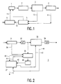
- Fig. 1 shows a block diagram of a television tuning system in accordance with the invention.
- the system of Fig. 1 includes an antenna unit 0, a tuner 1, an IF amplifier and detector 2, a baseband ghost cancellation unit 3, a signal processing unit 4 and a microcontroller 5.
- Antenna unit 0 is of a type which (a) receives television signals "from the air” via an antenna (not shown), and provides them to an output thereof, and (b) is capable of changing the directionality of the antenna, to change the reception quality of the television signals it receives, by either rotating the position of the antenna or adjusting the phase of the antenna.
- antenna unit 0 also has a control input coupled to a first output of microcontroller 5 for receiving a directionality control signal 10 produced by microcontroller 5 for controlling the position or phase of the antenna (or both, if the antenna has the ability to change both).
- Tuner 1 The output of antenna unit 0 is coupled to a first input of Tuner 1 which receives the television signals 11.
- Tuner 1 is of a type known to those skilled in the art which (a) receives television signals over a tuning frequency range (e.g., over the tuning frequency ranges of 181 channels), (b) tunes to a tuning frequency within the tuning frequency range, and (c) produces a tuned television signal at the tuning frequency.
- the tuner 1 also has a control input coupled to a second output of microcontroller 5 for receiving a tuning control signal produced by microcontroller 5 for controlling the frequency at which tuner 1 is set, and an output for supplying the tuned television signal.
- IF amplifier and detector 2 receives the tuned television signal.
- IF amplifier and detector 2 is of a type known to persons skilled in the art which (a) receives the tuned television signal, (b) increases its strength and (c) and converts it into a baseband television signal, which is made available at an output of IF amplifier and detector 2.
- the output of IF amplifier and detector 2 is coupled to an input of baseband ghost cancellation unit 3 which receives the baseband television signal.
- the baseband ghost cancellation unit 3 also has (a) a first output for supplying a ghost cancelled television signal produced therein from the baseband television signal, and (b) a second output for supplying to a first input of microcontroller 5 an non-adaption indicator signal 12 when the baseband ghost cancellation unit (i) is not capable of performing ghost cancellation or (ii) is unable to provide sufficient ghost cancellation to produce a ghost cancelled television signal which is a ghost-free television signal.
- the non-adaption indictor signal 12 is produced by baseband ghost cancellation unit 3 when the baseband ghost cancellation unit is unable to produce a ghost-free television signal.
- baseband ghost cancellation unit 3 Since a detailed discussion of baseband ghost cancellation units is provided in U.S. Patents Nos. 5,047,859, 5,111,298, 5,121,211, and 5,172,232, a detailed discussion of baseband ghost cancellation unit 3 is unnecessary. Nevertheless, to aid in the understanding of the invention, and in particular when the non-adaption indicator signal is produced, a simplified version of baseband ghost cancellation unit 3 is shown in Fig. 2 and now briefly discussed.
- Baseband ghost cancellation unit 3 of Fig. 2 includes a processor 31, an A/D converter 32, a ghost cancellation filter 33, a D/A converter 34, a RAM 35, a noise filter 36 and a microcontroller 37.
- the processor 31 has an input (which is the input of the baseband ghost cancellation unit 3 of Fig. 1) coupled to the output of the IF amplifier and detector of Fig. 1, for receiving the baseband television signal produced by IF amplifier and detector 2.
- the processor 31 (a) generates timing signals (only one of which is shown) from the baseband television signal for controlling timing functions of baseband ghost cancellation unit 3, and (b) supplies the baseband television signal via a first output to an input of A/D converter 32.
- A/D converter 32 converts the baseband television signal into a digital television signal.
- GCR indicator signal 39 which indicates where within the digital television signal the (now digital) GCR signal (which must be transmitted along with the transmitted original television signal in order for the baseband ghost cancellation unit used in accordance with the invention to be used and operated in accordance with the invention) is supposed to be located.
- GCR indicator signal 39 which is supplied from a second output of the processor 31 to a first input of RAM 35.
- RAM 35 samples, via a second input coupled to the output of the A/D converter 32, the digital television signal at the location where the (digital) GCR signal is supposed to be located.
- RAM 35 has a first output, coupled to a first input of microcontroller 37, for supplying the signal 40 that it sampled to the microcontroller 37.
- microcontroller 37 determines that the sampled signal 40 corresponds to the (digital) GCR signal, then it supplies a transfer signal 41 to RAM 35, via a first output of microcontroller 37 coupled to a third input of RAM 35.
- the transfer signal 41 is received by RAM 35, it supplies the (digital) GCR signal to noise filter 36, via a second output of RAM 35 coupled to an input of noise filter 36, which filters the (digital) GCR signal to remove noise.
- the noise reduced (digital) GCR signal 42 is supplied to microcontroller 37, via an output of the noise filter 36 to a second input of microcontroller 37, so that microcontroller 37 can determine ghost cancellation coefficients for ghost cancellation filter 33.
- Ghost cancellation filter 33 has a first input coupled to the output of A/D converter 32 for receiving the digital television signal, and a second input coupled to a second output of microcontroller 37 for receiving the ghost cancellation coefficients 43.
- ghost cancellation filter 33 can be a filter like the Zoran ZR33072 72-Tap Video-Rate Digital (Ghost Cancellation) Filter which is capable of performing baseband ghost cancellation on the digital television signal it receives on the basis of the ghost cancellation coefficients 43 it receives.
- ghost cancellation filter 33 has a second output, coupled to a third input of the microcontroller 37, for producing an overflow ("OVR") signal 44, like the Zoran ZR33072 filter, whenever ghost cancellation filter 33 is not producing a ghost cancelled digital television signal from which substantially ghost-free images can be produced as a result of the digital television signal and/or the ghost cancellation coefficients ghost cancellation filter 33 receives and uses.
- ghost cancellation filter 33 also has a second output, coupled to an input of D/A converter 34, for supplying the ghost cancelled digital television signal to D/A converter 34 for conversion back into an analog signal, i.e., into a ghost cancelled television signal.
- the ghost cancelled television signal is available at an output of the D/A converter 34 (which corresponds to the first output of the ghost cancellation unit 3 of Fig. 1).
- Microcontroller 37 of Fig. 2 can be a microprocessor, PROM, etc. which in addition to determining the ghost cancellation coefficients for use by the ghost cancellation filter 33 is also able to produce the non-adaption indicator signal 12 at a third output (which corresponds to the second output of the baseband ghost cancellation unit 3 of Fig. 1) whenever baseband ghost cancellation unit 3 is unable to produce a ghost-free television signal.
- microcontroller 37 produces the non-adaption indicator signal 12 in the following situations:
- baseband ghost cancellation unit 3 of Fig. 2 could also include a signal evaluation unit or processor (not shown) coupled to the second output of the ghost cancellation filter 33 or the output of the D/A convener 34 for measuring the quality of the signal at either, and supplying a triggering signal to the microcontroller 37 to produce the non-adaption indicator signal 12 if the signal at either output is deemed to be of a quality which would not enable ghost-free images to be obtained from that signal.
- the first output of baseband ghost cancellation unit 3 of Fig. 1 is coupled to an input of signal processing unit 4 which receives the ghost cancelled television signal.
- Signal processing unit 4 is of a type known to those skilled in the art. For purposes of this discussion and the invention, the only functions which signal processing unit 4 needs to perform are (a) to determine if the ghost cancelled television signal is properly tuned, on the basis of specific signal characteristics known to persons skilled in the art, and (b) if so, to provide a tuning lock indicator signal 13 at a first output thereof.
- the first output of signal processing unit 4 is coupled to a second input of microcontroller 5.
- Signal processing unit 4 also has a second output for making the ghost cancelled television signal available for further post processing.
- Microcontroller 5 which can be a microprocessor, PROM, etc. and is coupled to antenna control unit 0, tuner 1, baseband ghost cancellation unit 3 and signal processing unit 4, operates to cause the system of Fig. 1 to operate in accordance with the invention. Specifically, microcontroller 5 controls the operations of antenna unit 0 and tuner 1 to ensure that the system produces a properly tuned ghost-free television signal.
- Fig. 3 shows a method in accordance with the invention which my be performed by microcontroller 5. (For clarity purposes, the method of Fig. 3 is being discussed in terms of the system of Fig. 1.)
- the method of Fig. 3 begins either when a television having a system such as the one shown in Fig. 1 is turned on or a channel change request or selection is made by a viewer. (Since when a television is first turned on it typically selects the previous channel which it had been tuned to, turning on the television is essentially the same as requesting or selecting a channel change.
- channel change request will refer to either turning on a television having a system in accordance with the invention or requesting or selecting a channel change.
- the antenna of antenna unit 0 is either (a) set at a predetermined rotational position or setting, or phase position or setting, or (b) a previously set rotational position or setting, or phase position or setting.
- step S1 of Fig. 3 is performed.
- microcontroller 5 of Fig. 1 determines whether a requested channel (e.g., channel 4) is tuned in on the basis of whether it receives the tuning lock indicator signal from signal processor 4.
- step S2 of Fig. 3 is preformed.
- microcontroller 5 causes tuner 1 to be set to a particular tuning frequency via a tuning control signal.
- This causes baseband ghost cancellation unit 3 to determine ghost cancellation coefficients for use in performing ghost cancellation on the baseband television signal which results from the tuned television signal produced by tuner 1 being set to the particular tuning frequency.
- the first time step S2 is performed after a channel change request occurs (or the directionality of the antenna has been changed (see below)), microcontroller 5 causes tuner 1 to be set to an initial tuning frequency.
- the initial tuning frequency is the lowest frequency in the tuning frequency range for the requested channel (e.g., if channel 4, which has a tuning frequency range of between 66 and 68 MHz, is requested, then the initial tuning frequency would be 66 MHz).
- step S1 is performed again. If it is determined that the requested channel is not tuned in, then step S2 is repeated. This time, in the preferred embodiment, however, microprocessor 5 (in step S2) causes tuner 1 to be set to a different tuning frequency which is an incremental increase from the initial tuning frequency. Thereafter step S1 is repeated again, and, if tuning lock in has not occurred, then step S2 is also repeated again.
- step S2 is performed after tuner 1 is set at the initial tuning frequency, the tuning frequency which microcontroller 5 cause tuner 1 to be set at is an incremental increase from the previous tuning frequency which tuner 1 is set at. The incremental increase is preferably 62.5 KHz. Steps S1 and S2 are repeated in the previously described manner until (a) the requested channel is tuned in or (b) tuner 1 has been incremented to the highest tuning frequency in the tuning frequency range of the requested channel without tuning lock in having occurred.
- step S3 of Fig. 3 is performed.
- step S3 a determination is made as to whether ghost cancellation adaption has occurred, i.e. whether baseband ghost cancellation unit 3 is able to produce a ghost-free television signal. As mentioned above, this determination is made by baseband ghost cancellation unit 3, and the results thereof are provided by whether microprocessor 37 produces and microprocessor 5 receives the non-adaption indicator signal 12.
- step S4 of Fig. 3 is preformed.
- microcontroller 5 causes antenna unit 0 to change the directionality, i.e., the position or phase, of the antenna by a predetermined amount, e.g., one rotational position or setting, or one phase position or setting.
- baseband ghost cancellation unit 3 determine ghost cancellation coefficients for use in performing ghost cancellation on the baseband television signal which results from the change in directionality.
- step S4 step S1 is repeated. If tuning lock in does not occur, then step S3 is repeated. If tuning lock in does not occur (in step S1), then steps S2 and S1 are repeated until either (a) tuning lock in occurs or (b) tuner 1 has been incremented through the entire tuning frequency range of the requested channel without tuning lock in having occurred. If tuning lock does occur (in step S1), then step S3 is repeated. If at that point ghost cancellation adaption is does not occur, then step S4 is repeated and the directionality of the antenna changed again.
- Step S4 followed by steps S1-S3 (as necessary) are repeated until (a) ghost cancellation adaption occurs (i.e., baseband ghost cancellation unit 3 is able to produced a ghost-free television signal for a tuned in requested channel ) or (b) the directionality of the antenna has been set at every rotational position or setting, or phase position or setting without ghost cancellation adaption having occurred. If in step S3, it is determined that ghost cancellation adaption has occurred, then the desired result is obtained from the system of Fig. 1, i.e., production of a properly tuned ghost-free television signal.
- the system in accordance with the invention is capable of automatically changing the directionality of the antenna of antenna unit 0 to enable baseband ghost cancellation unit 3 to produce a ghost-free television signal
- the system can also make use of that capability to aid in tuning. Accordingly, if tuner 1 has been incremented though the entire tuning frequency range of a requested channel without tuning lock in having occurred, then the system can operate to change the directionality of the antenna to enable reception of a television signal which can be locked in.
- This procedure is incorporated into the method of Fig. 3. Specifically, if step S2 of Fig. 3 has been performed enough times so that tuner 1 has been incremented to the highest tuning frequency in the tuning frequency range of the requested channel without tuning lock in having occurred, then step S4 is performed, and the directionality of the antenna is changed.
- the desired setting information must be obtain each time a different channel is requested. Since time is required to obtain the desired setting information for each channel, it is desirable to store and use that information after it has been obtained (unless there is a change in the transmission path or the channel characteristics), each time that channel is requested.
- An embodiment of a system in accordance with the invention which can perform the task of obtaining the desired setting information for each channel, storing that information and then utilizing that information when that channel is again requested is shown in Fig. 4.
- the tuning system shown in Fig. 4 is essentially the same as the tuning system shown in Fig. 1 (like elements having the same reference numbers), except that the system shown in Fig. 3 also includes a storage device 6 coupled a microcontroller 5' via two communication paths, and additional communication paths between baseband ghost cancellation unit 3 and microcontroller 5'.
- the system shown in Fig. 3 operates in substantially the same way as the system shown in Fig. 1, except for the feature discussed hereinafter.
- Storage device 6 is a non-volatile memory unit, such as a RAM or the like, which is capable of (a) storing the desired setting information for each channel which a television can receive (e.g., 181), and (b) providing that information when requested to microprocessor 5'.
- Storage device 6 has an input for receiving the desired setting information for a requested channel from a fourth output of microprocessor 5', and an output for providing the desired setting information for a requested channel stored therein to microcontroller 5' via a fourth input coupled to the output of the storage device 6.
- Microcontroller 5' like microcontroller 5 of Fig. 1 is a microprocessor, PROM or the like. Microcontroller 5' operates in substantially the same manner as microcontroller 5 (described above), but is also capable of (a) receiving the ghost cancellation coefficients which produce a (properly tuned) ghost-free television signal for each requested channel from baseband ghost cancellation unit 3 (in particular, microcontroller 37 of Fig.
- microcontroller 5' can be programmed to perform the method shown and described with respect to Fig. 3 for each of the channels which a television including a tuning system in accordance with the invention can obtain individually during a television set-up operation to obtain the desired setting information for each channel.
- microcontroller 5 After the desired setting information for a requested channel has been stored in storage device 6 and is being used to control the system of Fig. 4, it is possible and beneficial to have microcontroller 5' periodically run through a check/update desired setting information method to make sure that stored and used desired setting information for a requested channel is resulting in the tuning system producing a (properly tuned) ghost-free television signal, and if not, for updating that information.
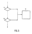
- Fig. 5 shows such a method.
- the method of Fig. 5 begins with step S1 of Fig. 3, i.e., a determination is made as to whether tuner 1 is tuned in. If it is, then steps S3 of Fig. 3 is performed, i.e., a determination is made as to whether ghost cancellation adaption has occurred. If it has, then a successful check has occurred. If, in the method of Fig. 5, it is determined that either tuner 1 is not tuned in (step S1) or ghost cancellation adaption has not occurred (step S3), then step S5 if performed. Step S5 involves repeating the method shown in Fig. 3 for a requested channel and then storing the new desired setting information in the storage device 6 for latter retrieval and use.
Abstract
Description
In step S1,
Claims (10)
- A television system comprisingcharacterized in that the system further comprisesan antenna unit (0) having an antenna for receiving a television signal, anda ghost cancellation unit (3) for effecting ghost cancellation on the television signal,means (3; 5) for determining as to whether sufficient ghost cancellation has occurred, andcontrol means (5) for changing a directionality of the antenna if sufficient ghost cancellation has not occurred.
- A television system as claimed in claim 1, characterized in that the ghost cancellation unit (3) is a baseband ghost cancellation unit coupled to the antenna unit (0) for receiving a baseband television signal and for performing a baseband ghost cancellation on the baseband television signal to produce a ghost cancelled television signal.
- A television system as claimed in claim 2, characterized in that means for determining (3; 5) comprise a detector (37; 5) for detecting whether the baseband ghost cancellation unit is able to produce a ghost free ghost cancelled television signal.
- A television system as claimed in claim 1, characterized in that said antenna is either a rotatable antenna or a phase adjustable antenna, said antenna unit (0) having antenna directionality change means for changing the directionality of said antenna, under the control of said control means (5), by rotating the position or adjusting the phase of said antenna.
- A television system as claimed in claim 2, characterized in that said antenna is set at a desired directionality setting when the ghost cancelled television signal is a ghost free television signal, and the system further comprises storage means (6) for storing the desired directionality setting.
- A television system as claimed in claim 5, characterized in that said ghost cancellation unit (3) produces ghost cancellation coefficients for use therein in producing the ghost cancelled television signal which is a ghost free television signal, and said ghost cancellation coefficients are storable in the storage means (6).
- A television system as claimed in claim 2, characterized in that the television system further comprises a tuner (1) coupled to said antenna unit (0) for receiving and tuning said television signal to a tuning frequency to produce the baseband television signal, the control means (5) being adapted to further control the tuning frequency if sufficient ghost cancellation has not occurred.
- A television system as claimed in claim 7, characterized in that said antenna is set at a desired directionality setting and the tuning frequency to which the television signal is tuned is at a desired tuning frequency setting when the ghost cancelled television signal is a ghost free television signal, and the system further comprises storage means (6) for storing the desired directionality setting and the desired tuning frequency setting.
- A method of receiving, comprising the steps of:receiving a television signal by means of an antenna unit (0) having an antenna, andeffecting (3) ghost cancellation on the television signal, characterized by the further steps of:determining (3; 5; S3) as to whether sufficient ghost cancellation has occurred, andchanging (5; S4) a directionality of the antenna if sufficient ghost cancellation has not occurred.
- A method as claimed in claim 9, characterized in that the step of receiving comprises a step of tuning (1) said television signal to a tuning frequency to produce the baseband television signal, the step of changing (5; S4) being adapted to further control the tuning frequency if sufficient ghost cancellation has not occurred.
Applications Claiming Priority (3)
| Application Number | Priority Date | Filing Date | Title |
|---|---|---|---|
| US496719 | 1990-03-21 | ||
| US08/496,719 US5654766A (en) | 1995-06-29 | 1995-06-29 | Television tuning systems and methods employing use of ghost cancellation and antenna directionality control to produce a ghost-free television signal |
| PCT/IB1996/000603 WO1997001924A2 (en) | 1995-06-29 | 1996-06-21 | Television tuning systems and methods to produce a ghost-free television signal |
Publications (2)
| Publication Number | Publication Date |
|---|---|
| EP0779006A2 EP0779006A2 (en) | 1997-06-18 |
| EP0779006B1 true EP0779006B1 (en) | 2000-10-11 |
Family
ID=23973836
Family Applications (1)
| Application Number | Title | Priority Date | Filing Date |
|---|---|---|---|
| EP96916274A Expired - Lifetime EP0779006B1 (en) | 1995-06-29 | 1996-06-21 | Television tuning systems and methods to produce a ghost-free television signal |
Country Status (7)
| Country | Link |
|---|---|
| US (2) | US5654766A (en) |
| EP (1) | EP0779006B1 (en) |
| JP (1) | JPH10505476A (en) |
| AT (1) | ATE196962T1 (en) |
| AU (1) | AU5908896A (en) |
| DE (1) | DE69610599T2 (en) |
| WO (1) | WO1997001924A2 (en) |
Families Citing this family (14)
| Publication number | Priority date | Publication date | Assignee | Title |
|---|---|---|---|---|
| US5179444A (en) * | 1990-10-09 | 1993-01-12 | North American Philips Corporation | System for echo cancellation comprising an improved ghost cancellation reference signal |
| US5654766A (en) * | 1995-06-29 | 1997-08-05 | Philips Electronics North America Corporation | Television tuning systems and methods employing use of ghost cancellation and antenna directionality control to produce a ghost-free television signal |
| JPH1023296A (en) * | 1996-07-05 | 1998-01-23 | Canon Inc | Signal-processing unit and its method |
| JP3803843B2 (en) * | 1997-09-09 | 2006-08-02 | 株式会社日立製作所 | Digital signal recording apparatus, recording / reproducing apparatus, and receiving / recording / reproducing apparatus |
| US6208388B1 (en) * | 1997-10-18 | 2001-03-27 | Lucent Technologies, Inc. | Channel responsive television input signal interface circuit and method |
| KR100269130B1 (en) * | 1997-11-21 | 2000-10-16 | 윤종용 | Digital and analog TV broadcast common-use receiver having single ghost canceller and ghost cancelleration method |
| US6307595B1 (en) * | 1998-01-13 | 2001-10-23 | Samsung Electronics Co., Ltd. | NTSC/DTV reception apparatus automatically conditioned for NTSC signal reception responsive to 4.5 MHz intercarrier |
| US6397369B1 (en) * | 1998-11-06 | 2002-05-28 | Acorn Technologies, Inc. | Device for using information about the extent of errors in a signal and method |
| JP4470045B2 (en) * | 2004-11-29 | 2010-06-02 | 船井電機株式会社 | Television broadcast receiver |
| JP4631411B2 (en) * | 2004-11-29 | 2011-02-16 | 船井電機株式会社 | Television broadcast receiver |
| JP2007318585A (en) * | 2006-05-29 | 2007-12-06 | Alps Electric Co Ltd | Digital signal receiver |
| EP1879377A3 (en) * | 2006-07-13 | 2010-06-16 | Panasonic Corporation | Portable Device |
| US20120225626A1 (en) * | 2009-11-17 | 2012-09-06 | Thomson Licensing | Reuse of a switch ic as a step attenuator |
| AU2012202200B2 (en) * | 2011-01-14 | 2015-04-16 | Electronic Controlled Systems, Inc. | Mobile television antenna with integral signal meter display |
Family Cites Families (13)
| Publication number | Priority date | Publication date | Assignee | Title |
|---|---|---|---|---|
| US4542326A (en) * | 1982-10-08 | 1985-09-17 | Heath Company | Automatic antenna positioning system |
| US4797950A (en) * | 1986-11-10 | 1989-01-10 | Kenneth Rilling | Multipath reduction system |
| US5121211A (en) * | 1990-10-09 | 1992-06-09 | North American Philips Corporation | System for echo cancellation comprising an improved ghost cancellation reference signal |
| US5119196A (en) * | 1990-06-25 | 1992-06-02 | At&T Bell Laboratories | Ghost cancellation of analog tv signals |
| US5172232A (en) * | 1990-10-09 | 1992-12-15 | North American Philips Corporation | Method and apparatus for communication channel identification and signal restoration |
| US5047859A (en) * | 1990-10-09 | 1991-09-10 | North American Philips Corporation | Method and apparatus for communication channel identification and signal restoration |
| US5111298A (en) * | 1990-10-09 | 1992-05-05 | North American Philips Corporation | Method and apparatus for communication channel identification and signal restoration |
| JPH05236393A (en) * | 1991-09-11 | 1993-09-10 | Toshiba Corp | Television receiver |
| JP2866775B2 (en) * | 1991-12-26 | 1999-03-08 | 三星電子株式会社 | Antenna moving device and method |
| US5483688A (en) * | 1993-01-22 | 1996-01-09 | Seiko Communications Holding N.V. | Adaptive automatic antenna tuning method and apparatus |
| KR950015100B1 (en) * | 1993-03-13 | 1995-12-21 | 엘지전자주식회사 | Tuning data control apparatus & method in tv monitor |
| US5491472A (en) * | 1993-12-28 | 1996-02-13 | Kurtz; Fred R. | RF switching with remote controllers dedicated to other devices |
| US5654766A (en) * | 1995-06-29 | 1997-08-05 | Philips Electronics North America Corporation | Television tuning systems and methods employing use of ghost cancellation and antenna directionality control to produce a ghost-free television signal |
-
1995
- 1995-06-29 US US08/496,719 patent/US5654766A/en not_active Expired - Fee Related
-
1996
- 1996-06-21 JP JP9504278A patent/JPH10505476A/en active Pending
- 1996-06-21 WO PCT/IB1996/000603 patent/WO1997001924A2/en active IP Right Grant
- 1996-06-21 AT AT96916274T patent/ATE196962T1/en not_active IP Right Cessation
- 1996-06-21 AU AU59088/96A patent/AU5908896A/en not_active Abandoned
- 1996-06-21 EP EP96916274A patent/EP0779006B1/en not_active Expired - Lifetime
- 1996-06-21 DE DE69610599T patent/DE69610599T2/en not_active Expired - Fee Related
- 1996-10-02 US US08/725,113 patent/US5907371A/en not_active Expired - Lifetime
Also Published As
| Publication number | Publication date |
|---|---|
| US5654766A (en) | 1997-08-05 |
| ATE196962T1 (en) | 2000-10-15 |
| DE69610599T2 (en) | 2001-05-31 |
| AU5908896A (en) | 1997-01-30 |
| EP0779006A2 (en) | 1997-06-18 |
| US5907371A (en) | 1999-05-25 |
| WO1997001924A3 (en) | 1997-02-27 |
| DE69610599D1 (en) | 2000-11-16 |
| WO1997001924A2 (en) | 1997-01-16 |
| JPH10505476A (en) | 1998-05-26 |
Similar Documents
| Publication | Publication Date | Title |
|---|---|---|
| EP0779006B1 (en) | Television tuning systems and methods to produce a ghost-free television signal | |
| US5065242A (en) | Deghosting apparatus using pseudorandom sequences | |
| US5341177A (en) | System to cancel ghosts generated by multipath transmission of television signals | |
| US5940028A (en) | System and method for aligning an antenna | |
| US7038733B2 (en) | Television receivers and methods for processing signal sample streams synchronously with line/frame patterns | |
| US5121211A (en) | System for echo cancellation comprising an improved ghost cancellation reference signal | |
| EP1252684A1 (en) | Rf receiving antenna system | |
| US20050185097A1 (en) | TV receiver and diversity receiving method | |
| US5661528A (en) | Apparatus and method for controlling operation of a high defination television adaptive equalizer | |
| US5568202A (en) | System for echo cancellation comprising an improved ghost cancellation reference signal | |
| EP0559344B1 (en) | Television tuner | |
| EP0702461B1 (en) | Reducing multipath fading | |
| US5878086A (en) | Method and apparatus for producing a deterministic sequence from an IIR filter | |
| US5138453A (en) | Ghost cancelling circuit having filter controlled by variable limiter | |
| US4939577A (en) | Receiver and demodulation circuit suitable for said receiver | |
| US5386243A (en) | Ghost signal cancellation system for television signals | |
| JP2940326B2 (en) | Ghost removal device | |
| JPS58117780A (en) | Ghost eliminating device | |
| KR960013227B1 (en) | Method and apparatus for ghost canceller filter coefficient weighted average processing | |
| JPH03132166A (en) | Ghost elimination device | |
| JPH03132165A (en) | Television receiver, ghost elimination device and ghost elimination control method | |
| EP0608934A2 (en) | Television signal reception | |
| JPH04245815A (en) | Sound volume controller | |
| JPH06197243A (en) | Noise reducing device | |
| KR19990043807A (en) | Antenna auto tuning method |
Legal Events
| Date | Code | Title | Description |
|---|---|---|---|
| PUAI | Public reference made under article 153(3) epc to a published international application that has entered the european phase |
Free format text: ORIGINAL CODE: 0009012 |
|
| AK | Designated contracting states |
Kind code of ref document: A2 Designated state(s): AT CH DE FR GB LI |
|
| 17P | Request for examination filed |
Effective date: 19970716 |
|
| RAP3 | Party data changed (applicant data changed or rights of an application transferred) |
Owner name: KONINKLIJKE PHILIPS ELECTRONICS N.V. |
|
| 17Q | First examination report despatched |
Effective date: 19990623 |
|
| GRAG | Despatch of communication of intention to grant |
Free format text: ORIGINAL CODE: EPIDOS AGRA |
|
| 17Q | First examination report despatched |
Effective date: 19990623 |
|
| GRAG | Despatch of communication of intention to grant |
Free format text: ORIGINAL CODE: EPIDOS AGRA |
|
| GRAH | Despatch of communication of intention to grant a patent |
Free format text: ORIGINAL CODE: EPIDOS IGRA |
|
| GRAH | Despatch of communication of intention to grant a patent |
Free format text: ORIGINAL CODE: EPIDOS IGRA |
|
| GRAA | (expected) grant |
Free format text: ORIGINAL CODE: 0009210 |
|
| AK | Designated contracting states |
Kind code of ref document: B1 Designated state(s): AT CH DE FR GB LI |
|
| REF | Corresponds to: |
Ref document number: 196962 Country of ref document: AT Date of ref document: 20001015 Kind code of ref document: T |
|
| REG | Reference to a national code |
Ref country code: CH Ref legal event code: EP |
|
| REF | Corresponds to: |
Ref document number: 69610599 Country of ref document: DE Date of ref document: 20001116 |
|
| ET | Fr: translation filed | ||
| PGFP | Annual fee paid to national office [announced via postgrant information from national office to epo] |
Ref country code: FR Payment date: 20010625 Year of fee payment: 6 Ref country code: AT Payment date: 20010625 Year of fee payment: 6 |
|
| PGFP | Annual fee paid to national office [announced via postgrant information from national office to epo] |
Ref country code: GB Payment date: 20010629 Year of fee payment: 6 |
|
| PLBE | No opposition filed within time limit |
Free format text: ORIGINAL CODE: 0009261 |
|
| STAA | Information on the status of an ep patent application or granted ep patent |
Free format text: STATUS: NO OPPOSITION FILED WITHIN TIME LIMIT |
|
| PGFP | Annual fee paid to national office [announced via postgrant information from national office to epo] |
Ref country code: DE Payment date: 20010821 Year of fee payment: 6 |
|
| PGFP | Annual fee paid to national office [announced via postgrant information from national office to epo] |
Ref country code: CH Payment date: 20010910 Year of fee payment: 6 |
|
| 26N | No opposition filed | ||
| REG | Reference to a national code |
Ref country code: GB Ref legal event code: IF02 |
|
| PG25 | Lapsed in a contracting state [announced via postgrant information from national office to epo] |
Ref country code: GB Free format text: LAPSE BECAUSE OF NON-PAYMENT OF DUE FEES Effective date: 20020621 Ref country code: AT Free format text: LAPSE BECAUSE OF NON-PAYMENT OF DUE FEES Effective date: 20020621 |
|
| PG25 | Lapsed in a contracting state [announced via postgrant information from national office to epo] |
Ref country code: LI Free format text: LAPSE BECAUSE OF THE APPLICANT RENOUNCES Effective date: 20020630 Ref country code: CH Free format text: LAPSE BECAUSE OF THE APPLICANT RENOUNCES Effective date: 20020630 |
|
| REG | Reference to a national code |
Ref country code: CH Ref legal event code: PL |
|
| PG25 | Lapsed in a contracting state [announced via postgrant information from national office to epo] |
Ref country code: DE Free format text: LAPSE BECAUSE OF NON-PAYMENT OF DUE FEES Effective date: 20030101 |
|
| GBPC | Gb: european patent ceased through non-payment of renewal fee |
Effective date: 20020621 |
|
| PG25 | Lapsed in a contracting state [announced via postgrant information from national office to epo] |
Ref country code: FR Free format text: LAPSE BECAUSE OF NON-PAYMENT OF DUE FEES Effective date: 20030228 |
|
| REG | Reference to a national code |
Ref country code: FR Ref legal event code: ST |