EP0778503A2 - Electrophotographic image forming device providing positive charge to toners - Google Patents
Electrophotographic image forming device providing positive charge to toners Download PDFInfo
- Publication number
- EP0778503A2 EP0778503A2 EP96308895A EP96308895A EP0778503A2 EP 0778503 A2 EP0778503 A2 EP 0778503A2 EP 96308895 A EP96308895 A EP 96308895A EP 96308895 A EP96308895 A EP 96308895A EP 0778503 A2 EP0778503 A2 EP 0778503A2
- Authority
- EP
- European Patent Office
- Prior art keywords
- toner
- toners
- developing
- image forming
- forming device
- Prior art date
- Legal status (The legal status is an assumption and is not a legal conclusion. Google has not performed a legal analysis and makes no representation as to the accuracy of the status listed.)
- Granted
Links
Images


Classifications
-
- G—PHYSICS
- G03—PHOTOGRAPHY; CINEMATOGRAPHY; ANALOGOUS TECHNIQUES USING WAVES OTHER THAN OPTICAL WAVES; ELECTROGRAPHY; HOLOGRAPHY
- G03G—ELECTROGRAPHY; ELECTROPHOTOGRAPHY; MAGNETOGRAPHY
- G03G21/00—Arrangements not provided for by groups G03G13/00 - G03G19/00, e.g. cleaning, elimination of residual charge
- G03G21/10—Collecting or recycling waste developer
-
- G—PHYSICS
- G03—PHOTOGRAPHY; CINEMATOGRAPHY; ANALOGOUS TECHNIQUES USING WAVES OTHER THAN OPTICAL WAVES; ELECTROGRAPHY; HOLOGRAPHY
- G03G—ELECTROGRAPHY; ELECTROPHOTOGRAPHY; MAGNETOGRAPHY
- G03G15/00—Apparatus for electrographic processes using a charge pattern
- G03G15/06—Apparatus for electrographic processes using a charge pattern for developing
- G03G15/08—Apparatus for electrographic processes using a charge pattern for developing using a solid developer, e.g. powder developer
- G03G15/0806—Apparatus for electrographic processes using a charge pattern for developing using a solid developer, e.g. powder developer on a donor element, e.g. belt, roller
- G03G15/0812—Apparatus for electrographic processes using a charge pattern for developing using a solid developer, e.g. powder developer on a donor element, e.g. belt, roller characterised by the developer regulating means, e.g. structure of doctor blade
-
- G—PHYSICS
- G03—PHOTOGRAPHY; CINEMATOGRAPHY; ANALOGOUS TECHNIQUES USING WAVES OTHER THAN OPTICAL WAVES; ELECTROGRAPHY; HOLOGRAPHY
- G03G—ELECTROGRAPHY; ELECTROPHOTOGRAPHY; MAGNETOGRAPHY
- G03G2215/00—Apparatus for electrophotographic processes
- G03G2215/06—Developing structures, details
- G03G2215/0602—Developer
- G03G2215/0604—Developer solid type
- G03G2215/0614—Developer solid type one-component
- G03G2215/0617—Developer solid type one-component contact development (i.e. the developer layer on the donor member contacts the latent image carrier)
Definitions
- the present invention relates to an electrophotographic type image forming device such as a laser printer, a facsimile machine, and a copying machine, and more particularly, to a type thereof having a developing roller and a photosensitive drum.
- reversal developing operation is widely performed on a negatively charged photosensitive drum having negatively chargeable characteristic with employing negatively charged toner.
- a widely available scorotoron charger is used so as to negatively charge the photosensitive drum, large volume of ozone will be generated. Further, the generated ozone may degrade the photosensitive member made of organic material and having negatively chargeable characteristic.
- toners are added with a silica as additives at a surface of the toner so as to enhance fluidity.
- an electrically conductive roller formed of an elastic material is used as the developing roller which carries toners, and the developing roller is depressed against the photosensitive drum.
- R & D activities have been made on the electrophotographic process in an attempt to avoid generation of waste toner in view of ecology.
- so called cleaner-less process has been proposed in which residual toners remaining on the photosensitive drum after transfer operation are carried to the developing unit at a proper timing at which charging process and electrostatic latent image forming process are not interrupted, and the residual toners are collected by the developing unit for reuse.
- a cleaning device such as a cleaning blade can be dispensed with, and therefore, can be prevented a damage to the photosensitive drum due to the direct contact of the blade therewith for toner scraping operation.
- residual toners can be relatively efficiently returned to the developing unit.
- the above described problem may not occur since the residual toners are not deposited onto the charger in the cleaner-less process.
- developing operation is performed by using a photosensitive drum having a negatively chargeable characteristic, negatively chargeable toners and a scorotoron charger which is a typical example of the non-contact type charger.
- electrolytic dissociation occurs in air in a space between the charger and the photosensitive drum to generate large amount of ozone. Further, the generated ozone may deteriorate an organic material such as the photosensitive drum having the negatively chargeable characteristic.
- a thickness regulation blade is provided for regulating a thickness of the toner layer carried on the developing roller.
- positive charging to the toners is required by the frictional contact between the thickness regulation blade and the toners.
- silica which is added for improving fluidity of the toner, normally provides a negatively chargeable characteristic, and therefore, the toners may not be charged to positive polarity but may be charged to negative polarity due to the domination of negatively chargeable characteristic of silica.
- the toner includes a resin base and the above described external additive provided at the surface of the resin base.
- the above described unwanted phenomena is due to the fact that, if such toner is sufficiently subjected to friction, chargeable characteristic of the resin is overriding, whereas if friction applied to such toner is insufficient, the chargeable characteristic of the additive formed over the surface of the resin becomes dominant.
- the toner layer on the developing roller has a large thickness, every toner does not subjected to sufficient friction by the thickness regulation blade, and as a result, the toners are charged to negative polarity, or amount or percentage of the positively charged toners are insufficient or small among the all toners in the toner layer.
- an object of the present invention to overcome the above described problems and to provide an improved image forming device capable of forming a high grade image by way of developing operation with using a photosensitive member having a positively chargeable characteristic and using toners having a positively chargeable characteristic.
- Another object of the present invention is to provide such image forming device capable of forming a high grade image while restraining generation of ozone as much as possible.
- an image forming device for forming an image on an image recording medium, the device including a photosensitive member having a positively chargeable characteristic, means for charging the photosensitive member to a positive polarity, means for forming an electrostatic latent image on the photosensitive member charged to the positive polarity, a developing roller for developing the electrostatic latent image into a toner image on the photosensitive member, the toner image being formed by a toner layer consisting of toners, means for regulating a thickness of the toner layer so that the toner layer on the developing roller amounts to not more than 0.5mg/cm 2 , and means for transferring the toner image onto an image recording medium.
- the regulation means and the photosensitive drum rub the toners positioned therebetween for charging the toners to a positive polarity.
- the photosensitive member In another aspect of the invention, there is provided the photosensitive member, the charging means, the electrostatic latent image forming means, the developing roller, the transferring means, and means for regulating a thickness of the toner layer so that from one to less than two toner particles are deposited in a radial direction of the developing roller.
- the regulation means and the photosensitive drum rub the deposited toners positioned between therebetween for charging the toners to a positive polarity.
- the photosensitive member the charging means, the electrostatic latent image forming means, the developing roller, means for regulating a thickness of the toner layer, and the transferring means.
- the regulation means and the photosensitive drum rub the toners positioned therebetween for charging the toners to a positive polarity.
- the charging means is out of contact from and in confrontation with the photosensitive member at a charging position whereby residual toners remaining on the photosensitive member after the toner transfer onto the image recording medium are carried on the photosensitive member, and the developing roller collects the residual toners after the residual toners carried on the photosensitive member are passed through the charging position.
- the laser printer includes a case 2, a feed unit 10 for supplying sheets P on which images are to be formed, a photosensitive drum 20 on which exposure, development and transfer process are successively performed for image formation, a fixing unit 70 for fixing an image transferred onto the sheet P from the photosensitive drum 20, and a discharge tray 77 onto which sheets P with the fixed images formed thereon are discharged through a sheet feed passage PP.
- the laser printer also provides a driving mechanism (not shown) for drivingly rotating the photosensitive drum 20.
- the laser printer 1 further includes, in order along a peripheral surface of the photosensitive drum 20, a laser scanner unit 30, a developing unit 50, a transfer roller 60, a cleaning roller 42, a discharge lamp 41 and a charger 40.
- the laser scanner unit 30 is adapted for forming the electrostatic latent image on the photosensitive drum 20.
- the developing unit 50 has a developing roller 56 for developing the electrostatic latent image on the photosensitive drum 20 with positively charged toners.
- the transfer roller 60 is adapted for transferring the developed toner image on the photosensitive drum 20 into the sheet P.
- the cleaning roller 42 is adapted for temporarily absorbing residual toners remaining on the photosensitive drum 20 after the transfer operation by the transfer roller 60 in order to return the absorbed toner to the developing unit 50 at a predetermined timing by co-operation with the photosensitive drum 20 in accordance with a cleaner-less system.
- the discharge lamp 41 is adapted for discharging residual potential remaining on the photosensitive drum 20 after transfer operation.
- the charger 40 is adapted for charging the photosensitive drum 20 after discharging operation so as to enable the drum to form the electrostatic latent image.
- the feed unit 10 includes a feeder case 3 disposed at the upper rear end of the case 2.
- a sheet-pressing plate 11 having a width substantially the same as the width of sheets P is supported within the feeder case 3.
- the sheet pressing plate has a rearmost edge pivotally supported to the feeder case 3.
- a compression spring 12 is disposed at the frontmost edge of the sheet pressing plate 11 for resiliently urging the pressing plate 11 upwardly.
- a sheet-supply roller 13 extending rightward and leftward, that is, in the direction perpendicular to the surface of Fig. 1, is rotatably supported to the sheet pressing plate 11.
- the driving mechanism (not shown) is also connected to the sheet feed roller 13 for driving the sheet-roller 13 to rotate at a proper sheet supplying timing.
- a sheet-cassette 14 capable of housing a plurality of stacked sheets cut into a predetermined shape is detachably and slantingly mounted in the case 3. Rotation of the sheet-supply roller 13 supplies an uppermost sheet P of the sheet stack contained in the sheet-supply cassette 14.
- a separation member 15 for preventing two sheets from being supplied at the same time is provided below the sheet-supply roller 13.
- a compression spring 16 is provided for resiliently urging the separating member 15 against the sheet-supply roller 13.
- a pair of resist rollers 17, 18 for aligning the leading edge of supplied sheet P are rotatably provided downstream of the sheet supply roller 13 in a sheet-transport direction.
- the photosensitive drum 20 is formed of a material having a positively chargeable characteristic.
- the material is, for example, a positively chargeable organic photosensitive material.
- the photosensitive drum 20 includes a hollow cylindrical aluminum sleeve 21 and a photoconductive layer 22 formed to a predetermined thickness, for example, about 20 ⁇ m, to the outer peripheral surface of the sleeve 21.
- the photo-conductive layer 22 is made of a poly-carbonate and a photo-conductive resin dispersed therein.
- the sleeve 21 is rotatably mounted on the case 2 in a grounded condition.
- the laser scanner unit 30 is disposed below the photosensitive drum 20 and includes a laser emitting unit 31 for generating the laser light L to form electrostatic latent image on the surface of the photosensitive drum 20, a five-sided polygon mirror 32 driven to rotate, a pair of lenses 33, 34, and a pair of reflection mirrors 35, 36. Because the laser scanner unit 30 is disposed below the photosensitive drum 20, the length of the image forming device in the sheet-transport direction can be reduced, so that the laser printer 1 can be provided in a more compact size. Also, the laser scanner unit 30 can emit the laser light L to form the electrostatic latent image on the surface of the photosensitive drum 20 without interference with the sheets transported in the sheet-transport pathway PP.
- the charger 40 is of a scorotoron type charger for generating a corona discharge from a tungsten charge wire.
- the charger 40 is held out of contact with the photosensitive drum 20. Because the photosensitive drum 20 is made of a material having a positively chargeable characteristic, the charger 40 is imparted with voltage of positive polarity. Further, because the cleaner-less method is applied, an because the charger 40 is out of contact with the photosensitive drum 20, the residual toner on the photosensitive drum 20 are not deposited on the charger 40.
- the discharge lamp 41 is provided by a light source, such as a LDE (laser emitting diode), an EL (electroluminescence) and a fluorescent lamp.
- the discharge lamp 41 is adapted for removing residual charge remaining on the photosensitive drum 20 after transfer operation in order to prevent the residual charge from affecting on the a subsequently formed electrostatic latent image, thereby degrading a resultant output image formed on the sheet P.
- the cleaning roller 42 is adapted for temporarily absorbing residual toners 53 remaining on the photosensitive drum 20 after transferring operation by changing biasing voltage, and for discharging the absorbed toners 53 to the photosensitive drum 20 at a proper timing at which exposure, developing and transferring operation on the photosensitive drum 20 are not interrupted by the toners, thereby returning the toners from the photosensitive drum 20 to the developing unit 50.
- the cleaning roller 42 is made of a foamable elastic material having an electrical conductivity such as a silicone rubber and polyurethane rubber to which biasing voltage is applicable.
- the developing unit 50 includes a developing case 4 and a double-cylindrical toner box 51 detachably mounted within the developing case 4.
- a drivingly rotatable agitator 52 and electrically insulative toners 53 having positively chargeable characteristic are contained in the toner box 51.
- a toner-supply port 51a is formed in the toner box 51.
- a toner-storage chamber 54 is provided at a front side of the toner box 51 for storing therein the toners 53 supplied from the toner box 51 through the toner-supply port 51a by the rotation of the agitator 52.
- a toner supply roller 55 is rotatably supported in the toner-storage chamber 54 and extends in a horizontal direction.
- a developing roller 56 is rotatably supported in contact with both the toner supply roller 55 and the photosensitive drum 20. The developing roller 56 extends in the horizontal direction so as to form a front wall of the toner-storage chamber 54.
- the toner-supply roller 55 is formed of a foamable elastic material such as silicone rubber and polyurethane rubber having electrical conductivity.
- a resistance at a portion in contact with the developing roller 56 is set to about 5 X 10 4 to 1 X 10 9 Ohms.
- the developing roller 56 has a relatively high hardness and is formed from a silicone rubber or polyurethane rubber having electrical conductive properties.
- the resistance value from the core electrode, which is applied with a developing bias voltage, to the outer peripheral surface in contact with the photosensitive drum 20 is set to about 5 x 10 4 to 1 x 10 7 Ohms.
- the toner supply roller 55 and the developing roller 56 are driven to be rotated in a clockwise direction in Fig. 2 by the driving mechanism (not shown).
- the developing roller 56 is adapted for performing developing operation using the tones 53 in co-operation with the photosensitive drum 20, and for collecting the residual toners returned onto the photosensitive drum 20 by the cleaning roller 42. More specifically, provided that the residual toners are carried on the photosensitive drum 20 by an amount of about 10% of entire toner amount used for the transfer operation, and such photosensitive drum 20 carrying the residual toner is exposed to laser beam by the laser scanner unit 30 so that the laser beam sufficiently reaches beneath the residual toners 53.
- the developing unit 50 by utilizing potential difference between an exposed portion and non-exposed portion regardless of the existence of the residual toners on the photosensitive drum 20, the residual toners 53 are moved to or collected by the developing rollers 56 if the residual toners 53 are affixed on the non-exposed portion of the photosensitive drum 20. Simultaneously, the residual toners 53 are maintained to be affixed on the photosensitive drum 20 if the residual toners have already been affixed to the exposed portion of the photosensitive drum 20. Concurrently, positively charged toners 53 are moved from the developing roller 56 to the photosensitive drum 20 if the residual toners 53 have not been affixed to the exposed portion of the photosensitive drum 20. That is, developing cycle and toner collecting cycle are performed concurrently.
- the toner-storage chamber 54 in the developing unit 50 is formed with a relatively large open space S above the toner supply roller 55. Therefore, even when a great deal of toner 53 are supplied from the toner box 51 through the toner-supply port 51a into the toner-storage chamber 54, the toners 53 will not become compressed in the toner-storage chamber 54. Therefore, the toners 53 will constantly be in a fluffed condition which can provide sufficient fluidity. This allows tne supply roller 55 to stably supply toner.
- a resilient thickness-regulating blade 57 formed in a thin-plate shape from stainless steel or phosphor bronze is dependingly attached to the developing case 4.
- the thickness-regulating blade 57 has a lowermost bending portion 57a in pressing contact with the developing roller 56.
- the thickness-regulating blade 57 regulates thickness of toners 53 supplied from the toner supply roller 55 and adhering to the surface of the developing roller 56 to a predetermined thickness of from one toner particle to less than two particles in the thickness direction of the toner layer. that is, to about 7 to 12 ⁇ m thick, which is equivalent to about not more than 0.5 mg/cm 2 with respect to the amount of the toners on the developing roller 56.
- the bent portion 57a has a radius of curvature of about 0.3 mm to insure a toner amount of 0.4 mg/cm 2 .
- developing bias and rotation number of the developing roller 56 will determine the minimum amount of toners on the developing roller 56. For example, if the toner amount on the developing roller is about 3mg/cm 2 , developing operation can be made with a sufficient toner density by using an ordinarily available developing bias and rotation numbers of the developing roller 56.
- the thickness of the toner layer is regulated by the thickness regulation blade 57 in such a manner that the toner amount on the developing roller is not more than 0.5mg/cm 2 , from one to less than two toner particles are stacked on the developing roller in a radial direction thereof to provide the toner layer.
- the toners 53 are sufficiently rubbed by the developing roller 56 and the thickness regulation blade 57, and are sufficiently charged.
- "+" mark is affixed to the toner particles which is indicative of the tonersimparted with sufficient charge.
- the toners 53 which have not been used for the developing operation are not accumulated on the contacting portion between the photosensitive drum 20 and the developing roller 56, but can be collected by the adhesion to the developing roller 56.
- the transfer roller 60 is freely rotatably disposed above and in contact with the photosensitive drum 20.
- the transfer roller 60 is formed from foamable elastic material and having electrical conductivity such as silicone rubber, and polyurethane rubber.
- the resistance value where the transfer roller 60 contacts the photosensitive drum 20 is set to about 1 x 10 6 to 1 x 10 10 Ohms. This resistance value is relatively large so that even though the transfer roller 60 contacts the surface of the photosensitive drum 20, the voltage applied to the transfer roller 60 will not destroy the photoconductive layer 22 formed on the photosensitive drum 20 yet the toner image on the photosensitive drum 20 can be reliably transferred onto the sheet P.
- the fixing unit 70 is provided downstream in the sheet-transport direction of the photosensitive drum 20.
- the fixing unit 20 includes a heat roller 71 housing therein a conventional halogen lamp and a pressing roller 72.
- a sheet P with the toner image transferred onto its lower surface is heated and pressed between the heat roller 71 and the pressing roller 72 so that the toner image is fixed onto the sheet P.
- a pair of transport rollers 75 and the discharge tray 77 are provided downstream in the sheet-transport direction from the fixing unit 70.
- the sheet roller 30, the photosensitive drum 20, the fixing unit 70, and the discharge tray 77 form a substantially linear sheet transport pathway PP along which sheets P supplied from the sheet supply cassette 14 are transported.
- the toner 53 is a non-magnetic and single component type toner.
- the toner is formed of polymerized material such as styreneacryl, which may be pulverized toner or a spherically shaped toner. Particle size of the toner 53 is in a range of from 6 to 12 ⁇ m.
- the toner 53 includes a base toner 201 and the additive 202 added to the base toner 201. Silica is used as the additive for imparting the resultant toner with fluidity.
- the base toner 201 contains resin, wax, carbon black and CCA (charge control agent such as nigrosine and triphenylmethane). The resultant toner has positively chargeable characteristic by the function of CCA.
- CCA charge control agent such as nigrosine and triphenylmethane
- Silica which is the example of the additives is a surface quality changing agent of the toner in order to enhance fluidity of the toner 53, and generally has negatively chargeable characteristic. Even though amino-deformation silica is known as a silica having positively chargeable characteristic, the positively chargeable silica generally provides insufficient fluidity. Accordingly, negatively chargeable silica having low polarity is often used as the additive. If charging amount is positively increased by the addition of a silica to the base toner, the silica is the positively chargeable silica, and if charging amount is negatively increased by the addition of a silica to the base toner, the silica is the negatively chargeable silica.
- the charging characteristic of the CCA contained in the base toner 201 becomes dominant, so that the toner 53 is charged to the positive polarity based on the charging characteristic of the base toner 201.
- the charging characteristic of the silica 202 which is exposed to the surface of the base toner 201 becomes dominant, so that the toner 53 is charged to negative polarity based on the charging characteristic of the silica 202.
- the additive can be provided with toner blocking preventing function, cleaning enhancement function, less damaging function to the photosensitive drum, image density improving function, and image quality improving function in addition to the enhancement of fluidity.
- Minute powders of colloidal silica, titanium oxide, and aluminum oxide (alumina) are available as additives other than silica.
- the present embodiment is advantageous in that not only the positively chargeable additives but also negatively chargeable additives can be used.
- particle size of the base toner 201 is in a range of from 6 to 12 ⁇ m
- particle size of silica 202 is in a range of from 10 to 30 ⁇ m. Therefore, in fact, silica 202 is extremely smaller than base toner 201 in comparison with the illustration shown in Fig. 5.
- the photosensitive drum 20 is driven to be rotated in the clockwise direction by the driving mechanism (not shown). Also, the toner supply roller 55 and the developing roller 56 are driven to be rotated in the clockwise direction. With this configuration, as shown in Fig. 6, the toner supply roller 55 and the developing roller 56 scrape against each other. Also, the thickness-regulating blade 57 pressingly abrades against the developing roller 56. The scraping and abrading action positively charges individual toner 53. The positively charged toner 53 adheres to the electrostatic latent image formed on the surface of the photosensitive drum 20 by the laser beam L, thereby performing reversal developing.
- the toner layer provided on the developing roller 56 by the thickness regulation blade 57 has toner amount of not more than 0.5mg/cm 2 . Therefore, from one to less than two toner particles are deposited on the developing roller 56 in the radial direction thereof in the toner layer. Accordingly, almost all the toner 53 undergo sufficient friction by the developing roller 56 and the thickness regulation blade 57, so that the toners 53 can be sufficiently positively charged. Consequently, the electrostatic latent image on the photosensitive drum 20 can be sufficiently developed with the sufficiently charged toners 53.
- the amount of toner adhering to the surface of the sheet needs to be about 0.78 mg/cm 2 .
- a development efficiency is set to slightly less than 100 percent, and peripheral velocity of the developing roller 56 is set twice as high as the peripheral velocity of the photosensitive drum 20. That is, at the nip portion, direct contact between the developing roller 56 and the photosensitive drum 20 is avoided, yet small amount of toners 53 can remain on the developing roller 56 by the Van der Waals attraction.
- the charging amount of the toner 53 depends on the temperature and humidity of the ambient environment. For example, in a low temperature and a low humidity environment of 10 degrees C and 20 percent humidity, the charge amount can be about 25 ⁇ C/g. This can decrease to about 20 ⁇ C/g at high temperature and high humidity conditions of about 32 degrees C and 80 percent humidity. As shown in Fig.
- the effective developing bias voltage of the developing roller 56 needs to be set to about 200 volts. Because the voltage of the electrostatic latent image formed on the surface of the photosensitive drum 20 is about 100 volts, the developing bias voltage of a power source E for applying voltage to the developing roller 56 is set to 300 volts.
- any charges remaining on the surface of the photosensitive drum 20 are removed by the discharge lamp 41. Then, as shown in Fig. 9, the charger 40 applies a uniform charge of about 800 volts to the surface of the photosensitive drum 20.
- the laser emitting unit 31 emits a laser beam L, which is scanned in a main scanning direction by the polygon mirror 32.
- the laser beam L then irradiates the surface of the photosensitive drum 20, after passing through the lenses 33, 34 and reflecting off the reflecting mirror 35, 36, to form the electrostatic latent image on the surface of the photosensitive drum 20.
- Voltage at the surface of the photosensitive drum 20 formed with the electrostatic latent image drops to about 100 volts as shown in Fig. 9.
- toner 53 Because positively charged toners 53 are adhering in a thickness of from one particle to less than two particles in the radial direction of the developing roller 56, while a developing bias voltage of about positive 300 volts is applied to the developing roller 56, the toner 53 is attracted to the voltage lower then itself, that is, to the electrostatic latent image voltage, which is about positive 100 volts, rather than to the high charge voltage of about 800 volts at areas other than the electrostatic latent image. Therefore, the toner 53 from the developing roller 56 are moved to only a portion where the electrostatic latent image is formed on the surface of the photosensitive drum 20. thereby producing a visible toner image.
- the toner image formed by developing the electrostatic latent image using toner 53 is transferred to the sheet P by the transfer roller 60. Afterward, the toner image is fixed to the sheet P by the fixing unit 70 and discharged onto the discharge tray 77.
- the sheet-transport pathway PP through which the sheet P supplied from the sheet-supply cassette 14 is transferred is approximately linear in shape. Therefore, an accurate and clean toner image can be formed even on thick sheets P such as envelopes, postcards and OHP films.
- the residual toners 53 remaining on the photosensitive drum 20 due to non-transfer to the sheet P when the sheet P is moved past the transfer roller 60 are temporarily absorbed to the cleaning roller 42 by changing biasing voltage of the cleaning roller 42.
- the temporarily absorbed toners 53 are then released from the cleaning roller 42 to the photosensitive drum 20 by changing the biasing voltage of the cleaning roller 42 at a proper timing at which subsequent exposure, developing and transfer operation are not interrupted by the toner releasing.
- the residual toners 53 on the photosensitive drum 20 are collected by the developing roller 56 and are subjected to recycling.
- Fig. 4 shows a developing unit according to a comparative example.
- a toner layer is provided by a thickness regulation blade 157 having a bending portion 157a whose radius of curvature is greater than that of the bending portion 57a of the thickness regulation blade 57 according to the first embodiment.
- the bending portion 157a is adapted for providing the toner layer having a toner amount of more than 0.5mg/cm 2 on the developing roller 56.
- the thickness of the toner layer on the developing roller 56 is such that not less than two toner particles are deposited on the developing roller 56 in a radial direction thereof.
- the toners 53 contain the additives having negatively chargeable characteristic such as silica, the toners which have not been sufficiently rubbed by the developing roller 56 and the thickness regulation blade 57 may become toners having reverse characteristic (negative polarity). Thus, excessive printing defect such as fogging results.
- Fig.10 shows a modified arrangement of a developing unit.
- a toner collection roller 156 is provided at a position beside the developing roller 56 and at a position close to the laser scanner unit 30 for exclusively collecting the residual toners 53.
- the developing roller 56 is adapted for exclusively performing developing operation.
- a developing case 104 is shaped such that the residual toners 53 collected by the toner collection roller 156 can be fed toward the toner supply roller 55 and the developing roller 56 by the rotation of the toner collection roller 156.
- the collection roller 156 is exclusively used for collecting the residual toners. Therefore, the residual toners can surely be collected with relatively simple construction.
- the developing operation is performed on the positively charged photosensitive drum 20 by using the non-magnetic, single component type and positively chargeable toners 53 containing negatively chargeable silica additives.
- the thickness of the toner layer on the developing roller 56 is regulated by the layer thickness regulating blade so that the layer amounts to not more than 0.5mg/cm 2 . Accordingly, from one toner particle to less than two particles are deposited on the photosensitive drum in a thickness direction of the toner layer.
- the residual toners 53 are carried in accordance with the rotation of the photosensitive drum 20, the residual toners 53 are not deposited onto the charger 4), because the charger 40 confronting the photosensitive drum 20 is out of contact with the photosensitive drum 20. Accordingly, charging performance of the charger 40 is not lowered. Consequently, high quality image can be formed on the sheet P.
- the photosensitive drum is relatively easily charged to positive polarity by the scorotoron charger. Further, generation amount of ozone due to electrolytic dissociation of the air between the charger 40 and the photosensitive drum 20 can be reduced to one tenth in comparison with a case where the photosensitive member is charged to negative polarity by the scorotoron charger.
- developing and toner collecting operation can be performed by the single roller. Therefore, compact developing unit results, and collection of the residual toners by the cleaner-less method can be achieved efficiently. Further, in this case, by performing the developing and collecting operation at independent cycle, collection of the residual toners can be carried with a relatively simple construction under the cleaner-less method. On the other hand, the developing and collecting operation can be performed almost concurrently in the same cycle. With such an arrangement, entire operation period can be shortened. Thus, image forming operation can be performed rapidly.
- the cleaning roller 42 is provided in order to efficiently perform the cleaner-less type toner collection,
- a cleaning brush to which a biasing voltage is applied can be provided so as to level the residual toners on the photosensitive drum 20.
- non-magnetic, single component type toners are used.
- two components type toners or magnetic toners are also available as far as the toners are chargeable to positive polarity and the positively chargeable photosensitive drum is employed.
- a drum shaped photosensitive member is used.
- a belt shaped photosensitive member is also available as far as it is formed of the positively chargeable material.
- the developing cycle and the toner collection cycle can be performed at different timing, and biasing voltage applied to the developing roller 56 relative to the photosensitive drum 20 is changed at every cycle.
- developing bias voltage is applied so that the positively charged toners 53 are moved (developed) from the developing roller 56 to the exposed area of the photosensitive drum 20
- collection bias voltage is applied so that the residual toners 53 are moved (collected) from the photosensitive drum 20 to the developing roller 56.
- various arrangement can be used so as to collect residual toners in the developing unit 50 using the developing roller 56.
- the above description concerns formation of a monochromatic image.
- color image formation is also available in the above described embodiment.
- the developing roller 56 and the photosensitive drum 20 are rotated in the same direction (these are moved in opposite directions at the confronting contacting surfaces).
- these rollers can be rotated in the opposite rotating direction (these are moved in the same direction at the contacting surfaces).
- the illustrated embodiment is arranged so as to collect the residual toners for recycling.
- the developing roller 56 etc. is effectively functioned in a case where a cleaning device having a cleaning blade is provided, or toners are returned from the cleaning device to the developing unit 50 by using a toner transport spring.
- the illustrated embodiment pertains to the laser printer.
- the present invention can be applied to a copying machine and a facsimile machine those being an electrophotographic type image forming device using toners.
Abstract
Description
- The present invention relates to an electrophotographic type image forming device such as a laser printer, a facsimile machine, and a copying machine, and more particularly, to a type thereof having a developing roller and a photosensitive drum.
- In an electrophotographic type image forming device, reversal developing operation is widely performed on a negatively charged photosensitive drum having negatively chargeable characteristic with employing negatively charged toner. However, if a widely available scorotoron charger is used so as to negatively charge the photosensitive drum, large volume of ozone will be generated. Further, the generated ozone may degrade the photosensitive member made of organic material and having negatively chargeable characteristic.
- With this reason, another image forming device has been provided in which a photosensitive drum having a positively chargeable characteristic is charged by the scorotoron charger in order to reduce amount of ozone generation, and positively charged toners are used for the developing operation.
- In the image forming device, strong demand has been made on the improvement on imaging quality. Therefore, in a electrophotographic type image forming device, a given degree of fluidity is required in the toners, so that the toners can be properly subjected to developing, transferring and cleaning on the photosensitive drum. To this effect, generally, toners are added with a silica as additives at a surface of the toner so as to enhance fluidity.
- In another aspect, in the electrophotographic type image forming device, in an impression type developing method, an electrically conductive roller formed of an elastic material is used as the developing roller which carries toners, and the developing roller is depressed against the photosensitive drum. Recently, in such type of developing method, R & D activities have been made on the electrophotographic process in an attempt to avoid generation of waste toner in view of ecology. As one example of the process, so called cleaner-less process has been proposed in which residual toners remaining on the photosensitive drum after transfer operation are carried to the developing unit at a proper timing at which charging process and electrostatic latent image forming process are not interrupted, and the residual toners are collected by the developing unit for reuse. According to the cleaner-less process, a cleaning device such as a cleaning blade can be dispensed with, and therefore, can be prevented a damage to the photosensitive drum due to the direct contact of the blade therewith for toner scraping operation. Thus, residual toners can be relatively efficiently returned to the developing unit.
- Because of the strong demand in enhancing the imaging quality in the electrophotographic type image forming device, charging process is extremely important capable of properly performing formation of the electrostatic latent image and developing operation. However, in the cleaner-less process, since the residual toners are carried on the photosensitive drum, the residual toners are inevitably passed through a charging position where a charging unit confronts the photosensitive drum. As a result, if a contact type charging unit is used, residual toners may be deposited onto a contacting portion between the charger and the photosensitive drum, which in turn lowers the charging efficiency, to thereby lower the developing efficiency and degrades an output image.
- On the other hand, if a charger of non-contact type is used, the above described problem may not occur since the residual toners are not deposited onto the charger in the cleaner-less process. However, in an electrophotographic type image forming device, developing operation is performed by using a photosensitive drum having a negatively chargeable characteristic, negatively chargeable toners and a scorotoron charger which is a typical example of the non-contact type charger. In this case, electrolytic dissociation occurs in air in a space between the charger and the photosensitive drum to generate large amount of ozone. Further, the generated ozone may deteriorate an organic material such as the photosensitive drum having the negatively chargeable characteristic.
- In an impression type developing system in which toners are carried on a surface of the developing roller and a photosensitive drum is in contact with the developing roller, a thickness regulation blade is provided for regulating a thickness of the toner layer carried on the developing roller. In this case, positive charging to the toners is required by the frictional contact between the thickness regulation blade and the toners. However, silica, which is added for improving fluidity of the toner, normally provides a negatively chargeable characteristic, and therefore, the toners may not be charged to positive polarity but may be charged to negative polarity due to the domination of negatively chargeable characteristic of silica.
- The toner includes a resin base and the above described external additive provided at the surface of the resin base. The above described unwanted phenomena is due to the fact that, if such toner is sufficiently subjected to friction, chargeable characteristic of the resin is overriding, whereas if friction applied to such toner is insufficient, the chargeable characteristic of the additive formed over the surface of the resin becomes dominant.
- That is, in the above phenomena, since the toner layer on the developing roller has a large thickness, every toner does not subjected to sufficient friction by the thickness regulation blade, and as a result, the toners are charged to negative polarity, or amount or percentage of the positively charged toners are insufficient or small among the all toners in the toner layer.
- As a result, insufficient developing portion is provided on the photosensitive drum due to the shortage of the positive charging, and consequently, degradation of image such as fogging may occur in an ultimate output image.
- It is therefore, an object of the present invention to overcome the above described problems and to provide an improved image forming device capable of forming a high grade image by way of developing operation with using a photosensitive member having a positively chargeable characteristic and using toners having a positively chargeable characteristic.
- Another object of the present invention is to provide such image forming device capable of forming a high grade image while restraining generation of ozone as much as possible.
- These and other objects of the present invention will be attained by providing an image forming device for forming an image on an image recording medium, the device including a photosensitive member having a positively chargeable characteristic, means for charging the photosensitive member to a positive polarity, means for forming an electrostatic latent image on the photosensitive member charged to the positive polarity, a developing roller for developing the electrostatic latent image into a toner image on the photosensitive member, the toner image being formed by a toner layer consisting of toners, means for regulating a thickness of the toner layer so that the toner layer on the developing roller amounts to not more than 0.5mg/cm2, and means for transferring the toner image onto an image recording medium. The regulation means and the photosensitive drum rub the toners positioned therebetween for charging the toners to a positive polarity.
- In another aspect of the invention, there is provided the photosensitive member, the charging means, the electrostatic latent image forming means, the developing roller, the transferring means, and means for regulating a thickness of the toner layer so that from one to less than two toner particles are deposited in a radial direction of the developing roller. The regulation means and the photosensitive drum rub the deposited toners positioned between therebetween for charging the toners to a positive polarity.
- In still another aspect of the invention, there is provided the photosensitive member, the charging means, the electrostatic latent image forming means, the developing roller, means for regulating a thickness of the toner layer, and the transferring means. The regulation means and the photosensitive drum rub the toners positioned therebetween for charging the toners to a positive polarity. The charging means is out of contact from and in confrontation with the photosensitive member at a charging position whereby residual toners remaining on the photosensitive member after the toner transfer onto the image recording medium are carried on the photosensitive member, and the developing roller collects the residual toners after the residual toners carried on the photosensitive member are passed through the charging position.
- The present invention will be more clearly understood from the following description, given by way of example only, with reference to the accompanying drawings in which:
- Fig. 1 is a cross-sectional side view showing a laser printer according to one embodiment of the present invention;
- Fig. 2 is an enlarged side view showing details of a developing unit and a photosensitive drum in the laser printer shown in Fig. 1;
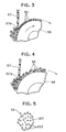
- Fig. 3 is an enlarged side view showing details of a developing roller and a thickness regulation blade in the laser printer shown in Fig. 1;
- Fig. 4 is an enlarged side view showing details of a developing roller and a thickness regulation blade in a comparative example;
- Fig. 5 is a schematic perspective view showing a toner used in the laser printer shown in Fig. 1;
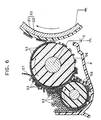
- Fig. 6 is an enlarged side view showing the developing unit of the laser printer shown in Fig. 1
- Fig. 7 is a graph showing the relationship between transmission density and amount of developing toner in the laser printer shown in Fig. 1;
- Fig. 8 is a graph showing the relationship between amount of developing toner and an effective bias voltage in the laser printer shown in Fig. 1;
- Fig. 9 is a graphical representation for description of voltage level in each developing section according to the reversal development in the laser printer shown in Fig. 1;
- Fig. 10 is an enlarged side view showing details of a photosensitive drum and a developing unit according to a second embodiment of the present invention.
- An image forming device according to a first embodiment of the present invention will be described with reference to Figs. 1 through 9, in which a reference is made on a laser printer.
- The laser printer includes a case 2, a
feed unit 10 for supplying sheets P on which images are to be formed, aphotosensitive drum 20 on which exposure, development and transfer process are successively performed for image formation, afixing unit 70 for fixing an image transferred onto the sheet P from thephotosensitive drum 20, and adischarge tray 77 onto which sheets P with the fixed images formed thereon are discharged through a sheet feed passage PP. - The laser printer also provides a driving mechanism (not shown) for drivingly rotating the
photosensitive drum 20. Around thephotosensitive drum 20, the laser printer 1 further includes, in order along a peripheral surface of thephotosensitive drum 20, alaser scanner unit 30, a developingunit 50, atransfer roller 60, acleaning roller 42, adischarge lamp 41 and acharger 40. Thelaser scanner unit 30 is adapted for forming the electrostatic latent image on thephotosensitive drum 20. The developingunit 50 has a developingroller 56 for developing the electrostatic latent image on thephotosensitive drum 20 with positively charged toners. Thetransfer roller 60 is adapted for transferring the developed toner image on thephotosensitive drum 20 into the sheet P. Thecleaning roller 42 is adapted for temporarily absorbing residual toners remaining on thephotosensitive drum 20 after the transfer operation by thetransfer roller 60 in order to return the absorbed toner to the developingunit 50 at a predetermined timing by co-operation with thephotosensitive drum 20 in accordance with a cleaner-less system. Thedischarge lamp 41 is adapted for discharging residual potential remaining on thephotosensitive drum 20 after transfer operation. Thecharger 40 is adapted for charging thephotosensitive drum 20 after discharging operation so as to enable the drum to form the electrostatic latent image. - Respective components constituting the laser printer 1 will next be described with reference to Figs. 1 through 5.
- In Fig. 1, the
feed unit 10 includes afeeder case 3 disposed at the upper rear end of the case 2. A sheet-pressingplate 11 having a width substantially the same as the width of sheets P is supported within thefeeder case 3. The sheet pressing plate has a rearmost edge pivotally supported to thefeeder case 3. Acompression spring 12 is disposed at the frontmost edge of thesheet pressing plate 11 for resiliently urging thepressing plate 11 upwardly. A sheet-supply roller 13 extending rightward and leftward, that is, in the direction perpendicular to the surface of Fig. 1, is rotatably supported to thesheet pressing plate 11. The driving mechanism (not shown) is also connected to thesheet feed roller 13 for driving the sheet-roller 13 to rotate at a proper sheet supplying timing. A sheet-cassette 14 capable of housing a plurality of stacked sheets cut into a predetermined shape is detachably and slantingly mounted in thecase 3. Rotation of the sheet-supply roller 13 supplies an uppermost sheet P of the sheet stack contained in the sheet-supply cassette 14. Aseparation member 15 for preventing two sheets from being supplied at the same time is provided below the sheet-supply roller 13. Acompression spring 16 is provided for resiliently urging the separatingmember 15 against the sheet-supply roller 13. A pair of resistrollers 17, 18 for aligning the leading edge of supplied sheet P are rotatably provided downstream of thesheet supply roller 13 in a sheet-transport direction. - In Figs. 1 and 2, the
photosensitive drum 20 is formed of a material having a positively chargeable characteristic. The material is, for example, a positively chargeable organic photosensitive material. More specifically, as shown in Fig. 2, thephotosensitive drum 20 includes a hollowcylindrical aluminum sleeve 21 and aphotoconductive layer 22 formed to a predetermined thickness, for example, about 20 µm, to the outer peripheral surface of thesleeve 21. The photo-conductive layer 22 is made of a poly-carbonate and a photo-conductive resin dispersed therein. Thesleeve 21 is rotatably mounted on the case 2 in a grounded condition. With this configuration, developing is possible by reversal development wherein positively chargedtoner 53 develops a positively charged electrostatic latent image formed on the surface of thephotosensitive drum 20. Thephotosensitive drum 20 is drivingly rotated in a clockwise direction in Fig. 2 by the driving mechanism (not shown). - In Fig. 1, the
laser scanner unit 30 is disposed below thephotosensitive drum 20 and includes alaser emitting unit 31 for generating the laser light L to form electrostatic latent image on the surface of thephotosensitive drum 20, a five-sided polygon mirror 32 driven to rotate, a pair oflenses laser scanner unit 30 is disposed below thephotosensitive drum 20, the length of the image forming device in the sheet-transport direction can be reduced, so that the laser printer 1 can be provided in a more compact size. Also, thelaser scanner unit 30 can emit the laser light L to form the electrostatic latent image on the surface of thephotosensitive drum 20 without interference with the sheets transported in the sheet-transport pathway PP. - The
charger 40 is of a scorotoron type charger for generating a corona discharge from a tungsten charge wire. Thecharger 40 is held out of contact with thephotosensitive drum 20. Because thephotosensitive drum 20 is made of a material having a positively chargeable characteristic, thecharger 40 is imparted with voltage of positive polarity. Further, because the cleaner-less method is applied, an because thecharger 40 is out of contact with thephotosensitive drum 20, the residual toner on thephotosensitive drum 20 are not deposited on thecharger 40. - The
discharge lamp 41 is provided by a light source, such as a LDE (laser emitting diode), an EL (electroluminescence) and a fluorescent lamp. Thedischarge lamp 41 is adapted for removing residual charge remaining on thephotosensitive drum 20 after transfer operation in order to prevent the residual charge from affecting on the a subsequently formed electrostatic latent image, thereby degrading a resultant output image formed on the sheet P. - The cleaning
roller 42 is adapted for temporarily absorbingresidual toners 53 remaining on thephotosensitive drum 20 after transferring operation by changing biasing voltage, and for discharging the absorbedtoners 53 to thephotosensitive drum 20 at a proper timing at which exposure, developing and transferring operation on thephotosensitive drum 20 are not interrupted by the toners, thereby returning the toners from thephotosensitive drum 20 to the developingunit 50. The cleaningroller 42 is made of a foamable elastic material having an electrical conductivity such as a silicone rubber and polyurethane rubber to which biasing voltage is applicable. - In Figs. 1 and 2, the developing
unit 50 includes a developingcase 4 and a double-cylindrical toner box 51 detachably mounted within the developingcase 4. A drivinglyrotatable agitator 52 and electricallyinsulative toners 53 having positively chargeable characteristic are contained in thetoner box 51. A toner-supply port 51a is formed in thetoner box 51. A toner-storage chamber 54 is provided at a front side of thetoner box 51 for storing therein thetoners 53 supplied from thetoner box 51 through the toner-supply port 51a by the rotation of theagitator 52. Atoner supply roller 55 is rotatably supported in the toner-storage chamber 54 and extends in a horizontal direction. A developingroller 56 is rotatably supported in contact with both thetoner supply roller 55 and the photosensitive drum 20.The developingroller 56 extends in the horizontal direction so as to form a front wall of the toner-storage chamber 54. - The toner-
supply roller 55 is formed of a foamable elastic material such as silicone rubber and polyurethane rubber having electrical conductivity. A resistance at a portion in contact with the developingroller 56 is set to about 5 X 10⁴ to 1 X 10⁹ Ohms. - Further, the developing
roller 56 has a relatively high hardness and is formed from a silicone rubber or polyurethane rubber having electrical conductive properties. The resistance value from the core electrode, which is applied with a developing bias voltage, to the outer peripheral surface in contact with thephotosensitive drum 20 is set to about 5 x 10⁴ to 1 x 10⁷ Ohms. Thetoner supply roller 55 and the developingroller 56 are driven to be rotated in a clockwise direction in Fig. 2 by the driving mechanism (not shown). - The developing
roller 56 is adapted for performing developing operation using thetones 53 in co-operation with thephotosensitive drum 20, and for collecting the residual toners returned onto thephotosensitive drum 20 by the cleaningroller 42. More specifically, provided that the residual toners are carried on thephotosensitive drum 20 by an amount of about 10% of entire toner amount used for the transfer operation, and suchphotosensitive drum 20 carrying the residual toner is exposed to laser beam by thelaser scanner unit 30 so that the laser beam sufficiently reaches beneath theresidual toners 53. Then, in the developingunit 50, by utilizing potential difference between an exposed portion and non-exposed portion regardless of the existence of the residual toners on thephotosensitive drum 20, theresidual toners 53 are moved to or collected by the developingrollers 56 if theresidual toners 53 are affixed on the non-exposed portion of thephotosensitive drum 20. Simultaneously, theresidual toners 53 are maintained to be affixed on thephotosensitive drum 20 if the residual toners have already been affixed to the exposed portion of thephotosensitive drum 20. Concurrently, positively chargedtoners 53 are moved from the developingroller 56 to thephotosensitive drum 20 if theresidual toners 53 have not been affixed to the exposed portion of thephotosensitive drum 20. That is, developing cycle and toner collecting cycle are performed concurrently. - As shown in Fig. 2, the toner-
storage chamber 54 in the developingunit 50 is formed with a relatively large open space S above thetoner supply roller 55. Therefore, even when a great deal oftoner 53 are supplied from thetoner box 51 through the toner-supply port 51a into the toner-storage chamber 54, thetoners 53 will not become compressed in the toner-storage chamber 54. Therefore, thetoners 53 will constantly be in a fluffed condition which can provide sufficient fluidity. This allowstne supply roller 55 to stably supply toner. - A resilient thickness-regulating
blade 57 formed in a thin-plate shape from stainless steel or phosphor bronze is dependingly attached to the developingcase 4. The thickness-regulatingblade 57 has alowermost bending portion 57a in pressing contact with the developingroller 56. The thickness-regulatingblade 57 regulates thickness oftoners 53 supplied from thetoner supply roller 55 and adhering to the surface of the developingroller 56 to a predetermined thickness of from one toner particle to less than two particles in the thickness direction of the toner layer. that is, to about 7 to 12 µm thick, which is equivalent to about not more than 0.5 mg/cm2 with respect to the amount of the toners on the developingroller 56. Thebent portion 57a has a radius of curvature of about 0.3 mm to insure a toner amount of 0.4 mg/cm2. Incidentally, developing bias and rotation number of the developingroller 56 will determine the minimum amount of toners on the developingroller 56. For example, if the toner amount on the developing roller is about 3mg/cm2, developing operation can be made with a sufficient toner density by using an ordinarily available developing bias and rotation numbers of the developingroller 56. - As shown in Fig. 3, on the developing
roller 56, since the thickness of the toner layer is regulated by thethickness regulation blade 57 in such a manner that the toner amount on the developing roller is not more than 0.5mg/cm2, from one to less than two toner particles are stacked on the developing roller in a radial direction thereof to provide the toner layer. As a result, almost all thetoners 53 are sufficiently rubbed by the developingroller 56 and thethickness regulation blade 57, and are sufficiently charged. (In Fig. 3, "+" mark is affixed to the toner particles which is indicative of the tonersimparted with sufficient charge.) Accordingly, the electrostatic latent image formed on thephotosensitive drum 20 is sufficiently developed with the sufficiently positively chargedtoners 53. Further, since from one to less than two toner particles are stacked on the developing roller in a radial direction thereof to provide the toner layer, thetoners 53 which have not been used for the developing operation are not accumulated on the contacting portion between thephotosensitive drum 20 and the developingroller 56, but can be collected by the adhesion to the developingroller 56. - The
transfer roller 60 is freely rotatably disposed above and in contact with thephotosensitive drum 20. Thetransfer roller 60 is formed from foamable elastic material and having electrical conductivity such as silicone rubber, and polyurethane rubber. The resistance value where thetransfer roller 60 contacts thephotosensitive drum 20 is set to about 1 x 10⁶ to 1 x 10¹⁰ Ohms. This resistance value is relatively large so that even though thetransfer roller 60 contacts the surface of thephotosensitive drum 20, the voltage applied to thetransfer roller 60 will not destroy thephotoconductive layer 22 formed on thephotosensitive drum 20 yet the toner image on thephotosensitive drum 20 can be reliably transferred onto the sheet P. - The fixing
unit 70 is provided downstream in the sheet-transport direction of thephotosensitive drum 20. The fixingunit 20 includes aheat roller 71 housing therein a conventional halogen lamp and apressing roller 72. A sheet P with the toner image transferred onto its lower surface is heated and pressed between theheat roller 71 and thepressing roller 72 so that the toner image is fixed onto the sheet P. - A pair of
transport rollers 75 and thedischarge tray 77 are provided downstream in the sheet-transport direction from the fixingunit 70. In the depicted embodiment, as shown in Fig. 1, thesheet roller 30, thephotosensitive drum 20, the fixingunit 70, and thedischarge tray 77 form a substantially linear sheet transport pathway PP along which sheets P supplied from thesheet supply cassette 14 are transported. - The
toner 53 is a non-magnetic and single component type toner. The toner is formed of polymerized material such as styreneacryl, which may be pulverized toner or a spherically shaped toner. Particle size of thetoner 53 is in a range of from 6 to 12 µm. As shown in Fig. 5, thetoner 53 includes abase toner 201 and the additive 202 added to thebase toner 201. Silica is used as the additive for imparting the resultant toner with fluidity. Thebase toner 201 contains resin, wax, carbon black and CCA (charge control agent such as nigrosine and triphenylmethane). The resultant toner has positively chargeable characteristic by the function of CCA. Silica which is the example of the additives is a surface quality changing agent of the toner in order to enhance fluidity of thetoner 53, and generally has negatively chargeable characteristic. Even though amino-deformation silica is known as a silica having positively chargeable characteristic, the positively chargeable silica generally provides insufficient fluidity. Accordingly, negatively chargeable silica having low polarity is often used as the additive. If charging amount is positively increased by the addition of a silica to the base toner, the silica is the positively chargeable silica, and if charging amount is negatively increased by the addition of a silica to the base toner, the silica is the negatively chargeable silica. - If the toner is subjected to sufficient friction by the
thickness regulation blade 57 and the developingroller 56, the charging characteristic of the CCA contained in thebase toner 201 becomes dominant, so that thetoner 53 is charged to the positive polarity based on the charging characteristic of thebase toner 201. On the other hand, if thetoner 53 is insufficiently rubbed, the charging characteristic of thesilica 202 which is exposed to the surface of thebase toner 201 becomes dominant, so that thetoner 53 is charged to negative polarity based on the charging characteristic of thesilica 202. - Further, the additive can be provided with toner blocking preventing function, cleaning enhancement function, less damaging function to the photosensitive drum, image density improving function, and image quality improving function in addition to the enhancement of fluidity. Minute powders of colloidal silica, titanium oxide, and aluminum oxide (alumina) are available as additives other than silica. However, the present embodiment is advantageous in that not only the positively chargeable additives but also negatively chargeable additives can be used. Incidentally, particle size of the
base toner 201 is in a range of from 6 to 12 µm, whereas particle size ofsilica 202 is in a range of from 10 to 30 µm. Therefore, in fact,silica 202 is extremely smaller thanbase toner 201 in comparison with the illustration shown in Fig. 5. - Operation of the laser printer 1 will next be described with reference to Figs. 1, 6 through 9.
- In Fig. 1, the
photosensitive drum 20 is driven to be rotated in the clockwise direction by the driving mechanism (not shown). Also, thetoner supply roller 55 and the developingroller 56 are driven to be rotated in the clockwise direction. With this configuration, as shown in Fig. 6, thetoner supply roller 55 and the developingroller 56 scrape against each other. Also, the thickness-regulatingblade 57 pressingly abrades against the developingroller 56. The scraping and abrading action positively chargesindividual toner 53. The positively chargedtoner 53 adheres to the electrostatic latent image formed on the surface of thephotosensitive drum 20 by the laser beam L, thereby performing reversal developing. - As described above, the toner layer provided on the developing
roller 56 by thethickness regulation blade 57 has toner amount of not more than 0.5mg/cm2. Therefore, from one to less than two toner particles are deposited on the developingroller 56 in the radial direction thereof in the toner layer. Accordingly, almost all thetoner 53 undergo sufficient friction by the developingroller 56 and thethickness regulation blade 57, so that thetoners 53 can be sufficiently positively charged. Consequently, the electrostatic latent image on thephotosensitive drum 20 can be sufficiently developed with the sufficiently chargedtoners 53. - As shown in Fig. 7, in order to obtain a transmission density (image density) of 2.0, the amount of toner adhering to the surface of the sheet needs to be about 0.78 mg/cm2. It should be noted that when the thickness-regulating
blade 57 regulates the toner amount on the developingroller 56 to 0.4 mg/cm2 as described above, a development efficiency is set to slightly less than 100 percent, and peripheral velocity of the developingroller 56 is set twice as high as the peripheral velocity of thephotosensitive drum 20. That is, at the nip portion, direct contact between the developingroller 56 and thephotosensitive drum 20 is avoided, yet small amount oftoners 53 can remain on the developingroller 56 by the Van der Waals attraction. - The charging amount of the
toner 53 depends on the temperature and humidity of the ambient environment. For example, in a low temperature and a low humidity environment of 10 degrees C and 20 percent humidity, the charge amount can be about 25 µC/g. This can decrease to about 20 µC/g at high temperature and high humidity conditions of about 32 degrees C and 80 percent humidity. As shown in Fig. 8, in order to obtain the predetermined developing toner amount of approximately 0.78 mg/cm2 in the low temperature and low humidity environment as indicated by the one-dot chain line or in the high temperature and high humidity environment as indicated by the two-dot chain line, under the condition that the developingroller 56 is driven in the same rotational direction as thephotosensitive drum 20, the effective developing bias voltage of the developingroller 56 needs to be set to about 200 volts. Because the voltage of the electrostatic latent image formed on the surface of thephotosensitive drum 20 is about 100 volts, the developing bias voltage of a power source E for applying voltage to the developingroller 56 is set to 300 volts. - When image forming processes are started under the above described set voltage, any charges remaining on the surface of the
photosensitive drum 20 are removed by thedischarge lamp 41. Then, as shown in Fig. 9, thecharger 40 applies a uniform charge of about 800 volts to the surface of thephotosensitive drum 20. - The
laser emitting unit 31 emits a laser beam L, which is scanned in a main scanning direction by thepolygon mirror 32. The laser beam L then irradiates the surface of thephotosensitive drum 20, after passing through thelenses mirror photosensitive drum 20. Voltage at the surface of thephotosensitive drum 20 formed with the electrostatic latent image drops to about 100 volts as shown in Fig. 9. - Because positively charged
toners 53 are adhering in a thickness of from one particle to less than two particles in the radial direction of the developingroller 56, while a developing bias voltage of about positive 300 volts is applied to the developingroller 56, thetoner 53 is attracted to the voltage lower then itself, that is, to the electrostatic latent image voltage, which is about positive 100 volts, rather than to the high charge voltage of about 800 volts at areas other than the electrostatic latent image. Therefore, thetoner 53 from the developingroller 56 are moved to only a portion where the electrostatic latent image is formed on the surface of thephotosensitive drum 20. thereby producing a visible toner image. - The toner image formed by developing the electrostatic latent
image using toner 53 is transferred to the sheet P by thetransfer roller 60. Afterward, the toner image is fixed to the sheet P by the fixingunit 70 and discharged onto thedischarge tray 77. As mentioned above, the sheet-transport pathway PP through which the sheet P supplied from the sheet-supply cassette 14 is transferred is approximately linear in shape. Therefore, an accurate and clean toner image can be formed even on thick sheets P such as envelopes, postcards and OHP films. - On the other hand, in Fig. 1, the
residual toners 53 remaining on thephotosensitive drum 20 due to non-transfer to the sheet P when the sheet P is moved past thetransfer roller 60 are temporarily absorbed to the cleaningroller 42 by changing biasing voltage of the cleaningroller 42. The temporarily absorbedtoners 53 are then released from the cleaningroller 42 to thephotosensitive drum 20 by changing the biasing voltage of the cleaningroller 42 at a proper timing at which subsequent exposure, developing and transfer operation are not interrupted by the toner releasing. Then theresidual toners 53 on thephotosensitive drum 20 are collected by the developingroller 56 and are subjected to recycling. - Fig. 4 shows a developing unit according to a comparative example. A toner layer is provided by a
thickness regulation blade 157 having a bendingportion 157a whose radius of curvature is greater than that of the bendingportion 57a of thethickness regulation blade 57 according to the first embodiment. The bendingportion 157a is adapted for providing the toner layer having a toner amount of more than 0.5mg/cm2 on the developingroller 56. In Fig. 4, the thickness of the toner layer on the developingroller 56 is such that not less than two toner particles are deposited on the developingroller 56 in a radial direction thereof. Accordingly, in the comparative example, because thetoners 53 on the developing roller are not sufficiently rubbed by the developingroller 56 and thethickness regulation blade 157, large volume oftoners 53 have not been sufficiently charged. (In Fig. 4, similar to Fig. 3, "+" mark is affixed to the toner particles which is indicative of the toners imparted with sufficient charge.) The electrostatic latent image on thephotosensitive drum 56 cannot be sufficiently developed with the insufficiently chargedtoners 53. Accordingly, printing defect such as fogging may be generated in the final output image. Particularly, if thetoners 53 contain the additives having negatively chargeable characteristic such as silica, the toners which have not been sufficiently rubbed by the developingroller 56 and thethickness regulation blade 57 may become toners having reverse characteristic (negative polarity). Thus, excessive printing defect such as fogging results. - Fig.10 shows a modified arrangement of a developing unit. In the modification, a
toner collection roller 156 is provided at a position beside the developingroller 56 and at a position close to thelaser scanner unit 30 for exclusively collecting theresidual toners 53. In this case, the developingroller 56 is adapted for exclusively performing developing operation. Further, in this case, a developingcase 104 is shaped such that theresidual toners 53 collected by thetoner collection roller 156 can be fed toward thetoner supply roller 55 and the developingroller 56 by the rotation of thetoner collection roller 156. In this modified embodiment, thecollection roller 156 is exclusively used for collecting the residual toners. Therefore, the residual toners can surely be collected with relatively simple construction. - In the laser printer 1 according to the foregoing embodiments, the developing operation is performed on the positively charged
photosensitive drum 20 by using the non-magnetic, single component type and positivelychargeable toners 53 containing negatively chargeable silica additives. Here, the thickness of the toner layer on the developingroller 56 is regulated by the layer thickness regulating blade so that the layer amounts to not more than 0.5mg/cm2. Accordingly, from one toner particle to less than two particles are deposited on the photosensitive drum in a thickness direction of the toner layer. Consequently, almost all the toners are sufficiently subjected to friction by the developing roller and the thickness regulation blade, and are sufficiently charged to positive polarity, Therefore, the electrostatic latent image on the photosensitive member is sufficiently developed with the sufficiently charged toners. As a result, printing defect such as fogging can be reduced, and high quality image can be provided. Further, because positive charging is performed by the scorotoron charger, ozone generation amount can be reduced. - Further, in the laser printer 1 according to the depicted embodiment, despite cf the fact that the
residual toners 53 are carried in accordance with the rotation of thephotosensitive drum 20, theresidual toners 53 are not deposited onto the charger 4), because thecharger 40 confronting thephotosensitive drum 20 is out of contact with thephotosensitive drum 20. Accordingly, charging performance of thecharger 40 is not lowered. Consequently, high quality image can be formed on the sheet P. Further, the photosensitive drum is relatively easily charged to positive polarity by the scorotoron charger. Further, generation amount of ozone due to electrolytic dissociation of the air between thecharger 40 and thephotosensitive drum 20 can be reduced to one tenth in comparison with a case where the photosensitive member is charged to negative polarity by the scorotoron charger. - Further, developing and toner collecting operation can be performed by the single roller. Therefore, compact developing unit results, and collection of the residual toners by the cleaner-less method can be achieved efficiently. Further, in this case, by performing the developing and collecting operation at independent cycle, collection of the residual toners can be carried with a relatively simple construction under the cleaner-less method. On the other hand, the developing and collecting operation can be performed almost concurrently in the same cycle. With such an arrangement, entire operation period can be shortened. Thus, image forming operation can be performed rapidly.
- While the invention has been described in detail and with reference to the specific embodiments thereof, it would be apparent to those skilled in the art that various changes and modifications may be made therein without departing from the spirit and scope of the invention. For example, in the above described embodiment, the cleaning
roller 42 is provided in order to efficiently perform the cleaner-less type toner collection, However, instead of the cleaningroller 42, or in addition thereto, a cleaning brush to which a biasing voltage is applied can be provided so as to level the residual toners on thephotosensitive drum 20. - Further, in the illustrated embodiment, non-magnetic, single component type toners are used. However, two components type toners or magnetic toners are also available as far as the toners are chargeable to positive polarity and the positively chargeable photosensitive drum is employed.
- Furthermore, in the depicted embodiment, a drum shaped photosensitive member is used. However, a belt shaped photosensitive member is also available as far as it is formed of the positively chargeable material.
- As an further alternative of the developing
unit 50, the developing cycle and the toner collection cycle can be performed at different timing, and biasing voltage applied to the developingroller 56 relative to thephotosensitive drum 20 is changed at every cycle. For example, in the developing cycle, developing bias voltage is applied so that the positively chargedtoners 53 are moved (developed) from the developingroller 56 to the exposed area of thephotosensitive drum 20, and in the collection cycle, collection bias voltage is applied so that theresidual toners 53 are moved (collected) from thephotosensitive drum 20 to the developingroller 56. In this way, various arrangement can be used so as to collect residual toners in the developingunit 50 using the developingroller 56. - Moreover, the above description concerns formation of a monochromatic image. However, color image formation is also available in the above described embodiment. Further, in the depicted embodiment, the developing
roller 56 and thephotosensitive drum 20 are rotated in the same direction (these are moved in opposite directions at the confronting contacting surfaces). However, these rollers can be rotated in the opposite rotating direction (these are moved in the same direction at the contacting surfaces). Furthermore, the illustrated embodiment is arranged so as to collect the residual toners for recycling. For recycling the toners, the developingroller 56 etc. is effectively functioned in a case where a cleaning device having a cleaning blade is provided, or toners are returned from the cleaning device to the developingunit 50 by using a toner transport spring. - Further, the illustrated embodiment pertains to the laser printer. However, the present invention can be applied to a copying machine and a facsimile machine those being an electrophotographic type image forming device using toners.
Claims (18)
- An image forming device for forming an image on an image recording medium comprising:a photosensitive member having a positively chargeable characteristic;means for charging the photosensitive member to a positive polarity;means for forming an electrostatic latent image on the photosensitive member charged to the positive polarity;a developing roller for developing the electrostatic latent image into a toner image on the photosensitive member, the toner image being formed by a toner layer consisting of toners;means for regulating a thickness of the toner layer, the regulation means and the photosensitive drum rubbing the toners positioned therebetween for charging the toners to a positive polarity; and,means for transferring the toner image onto an image recording medium.
- The image forming device as claimed in claim 1, wherein the toner is made of a non-magnetic single component type toner.
- The image forming device as claimed in claim 1 or 2, wherein the toner comprises: a base having a positively chargeable characteristic, and an additive formed over an outer surface of the base and having a negatively chargeable characteristic.
- The image forming device as claimed in claim 1, 2 or 3, wherein each toner has a particle size in a range of from 6 to 12 µm.
- The image forming device as claimed in any preceding claim, wherein the regulating means comprises a layer thickness regulation blade provided with a bending portion, the bending portion being disposed in contact with the developing roller.
- The image forming device as claimed in claim 5, wherein the thickness regulation blade is made of a resilient material.
- The image forming device as claimed in claim 5 or 6, wherein the bending portion has a radius of a curvature of 0.3mm.
- The image forming device as claimed in claim 5, 6 or 7, further comprising a developing case for rotatably installing therein the developing roller, the thickness regulation blade being dependingly attached to the developing case.
- The image forming device as claimed in claim 8, further comprising a toner box detachably mounted within the developing case;a toner supply roller being rotatably supplied in the developing case and in contact with the developing roller;an agitator drivingly rotatable in the toner box.
- The image forming device as claimed in any one of claims 1 to 7, further comprising:a developing case in which the developing roller is installed;a toner supply roller disposed in the developing case for supplying the toners to the developing roller; anda toner collection roller disposed in the developing case for collecting residual toners on the photosensitive member and delivering the collected residual toners toward the toner supply roller.
- The image forming device as claimed in any preceding claim, wherein the charging means comprises a scorotoron charger.
- The image forming device as claimed in any preceding claim, wherein the developing roller is made of a material selected from the group consisting of silicone rubber and polyurethane rubber.
- The image forming device as claimed in any preceding claim, wherein the charging means is out of contact from and in confrontation with the photosensitive member at a charging position whereby residual toners remaining on the photosensitive member after the toner transfer onto the image recording medium are carried on the photosensitive member, and the developing roller collects the residual toners after the residual toners carried on the photosensitive member are passed through the charging position.
- The image forming device as claimed in claim 13, further comprising a toner collection roller for exclusively collecting the residual toners on the photosensitive member, the developing roller exclusively performing developing operation.
- The image forming device as claimed in claim 14, wherein the toner collection roller is positioned upstream of the charging means for temporarily absorbing residual toners before the residual toners reach the charging position, and for discharging the temporarily absorbed toners onto the photosensitive member at a predetermined timing.
- The image forming device as claimed in claim 14 or 15, wherein the toner collection roller is formed of a foamable elastic material having an electrical conductivity.
- The image forming device as claimed in any preceding claim wherein:
said means for regulating a thickness of the toner layer is so that from one to less than two toner particles are deposited in a radial direction of the developing roller. - The image forming device as claimed in any preceding claim wherein:
said means for regulating a thickness of the toner layer is so that the toner layer on the developing roller amounts to not more than 0.5mg/cm2.
Applications Claiming Priority (6)
| Application Number | Priority Date | Filing Date | Title |
|---|---|---|---|
| JP32091595A JPH09160378A (en) | 1995-12-08 | 1995-12-08 | Image forming device |
| JP320915/95 | 1995-12-08 | ||
| JP32091595 | 1995-12-08 | ||
| JP34371695A JPH09185257A (en) | 1995-12-28 | 1995-12-28 | Image forming device |
| JP34371695 | 1995-12-28 | ||
| JP343716/95 | 1995-12-28 |
Publications (3)
| Publication Number | Publication Date |
|---|---|
| EP0778503A2 true EP0778503A2 (en) | 1997-06-11 |
| EP0778503A3 EP0778503A3 (en) | 1999-05-12 |
| EP0778503B1 EP0778503B1 (en) | 2003-04-16 |
Family
ID=26570271
Family Applications (1)
| Application Number | Title | Priority Date | Filing Date |
|---|---|---|---|
| EP96308895A Expired - Lifetime EP0778503B1 (en) | 1995-12-08 | 1996-12-09 | Electrophotographic image forming device providing positive charge to toners |
Country Status (3)
| Country | Link |
|---|---|
| US (1) | US5752146A (en) |
| EP (1) | EP0778503B1 (en) |
| DE (1) | DE69627460T2 (en) |
Families Citing this family (13)
| Publication number | Priority date | Publication date | Assignee | Title |
|---|---|---|---|---|
| JP3495873B2 (en) * | 1997-03-11 | 2004-02-09 | キヤノン株式会社 | Image forming device |
| JP3691249B2 (en) * | 1998-06-02 | 2005-09-07 | シャープ株式会社 | Developing device using one-component developer |
| US6195522B1 (en) * | 1998-11-24 | 2001-02-27 | Brother Kogyo Kabushiki Kaisha | Developing device |
| US6021298A (en) * | 1999-01-26 | 2000-02-01 | Aetas Technology Corp. | Embedded doctor blade arrangement |
| US6352771B1 (en) * | 1999-02-24 | 2002-03-05 | Mearthane Products Corporation | Conductive urethane roller |
| US6021299A (en) * | 1999-05-27 | 2000-02-01 | Oki Data America, Inc. | Precision blade for metering toner on developing roller |
| JP2001022176A (en) * | 1999-07-13 | 2001-01-26 | Canon Inc | Developing device, and process cartridge and image forming device equipped with developing device |
| JP2001281985A (en) * | 2000-03-30 | 2001-10-10 | Sharp Corp | Developing device |
| US6806014B2 (en) | 2001-08-21 | 2004-10-19 | Aetas Technology, Inc. | Monocomponent developing arrangement for electrophotography |
| JP2004252420A (en) * | 2003-01-31 | 2004-09-09 | Canon Inc | Developing device, process cartridge, and image forming apparatus |
| US7013104B2 (en) * | 2004-03-12 | 2006-03-14 | Lexmark International, Inc. | Toner regulating system having toner regulating member with metallic coating on flexible substrate |
| US8892011B2 (en) * | 2011-07-29 | 2014-11-18 | Brother Kogyo Kabushiki Kaisha | Developing apparatus having thickness regulating member |
| JP5611381B2 (en) * | 2012-03-19 | 2014-10-22 | キヤノン株式会社 | Developing device, process cartridge, and image forming apparatus |
Family Cites Families (19)
| Publication number | Priority date | Publication date | Assignee | Title |
|---|---|---|---|---|
| JPS5290939A (en) * | 1976-01-26 | 1977-07-30 | Canon Inc | Electrostatic printing |
| JPS5466139A (en) * | 1977-11-04 | 1979-05-28 | Minolta Camera Co Ltd | Electrophotographic copier |
| JPS5741677A (en) * | 1980-08-25 | 1982-03-08 | Fuji Xerox Co Ltd | Cleaning-developing-device |
| US4673631A (en) * | 1984-12-15 | 1987-06-16 | Canon Kabushiki Kaisha | Toner, charge-imparting material and composition containing metal complex |
| EP0212669B1 (en) * | 1985-08-30 | 1991-10-16 | Konica Corporation | Method for the development of an electrostatic latent image |
| US4769676A (en) * | 1986-03-04 | 1988-09-06 | Kabushiki Kaisha Toshiba | Image forming apparatus including means for removing residual toner |
| US4833059A (en) * | 1986-03-18 | 1989-05-23 | Kabushiki Kaisha Toshiba | Developing method using one-component non-magnetic toner with positive frictional charge |
| US4920916A (en) * | 1988-03-16 | 1990-05-01 | Minolta Camera Kabushiki Kaisha | Electrostatic latent image developing device |
| JPH07117808B2 (en) * | 1988-06-20 | 1995-12-18 | シャープ株式会社 | Image forming device |
| JP3014103B2 (en) * | 1989-07-17 | 2000-02-28 | ミノルタ株式会社 | Developing device |
| JPH03118563A (en) * | 1989-09-29 | 1991-05-21 | Mita Ind Co Ltd | Image forming device |
| JP3090485B2 (en) * | 1990-04-26 | 2000-09-18 | 株式会社リコー | toner |
| JP2714234B2 (en) * | 1990-07-31 | 1998-02-16 | 株式会社東芝 | Image forming device |
| JPH04337760A (en) * | 1991-05-15 | 1992-11-25 | Seiko Epson Corp | Image forming device |
| JPH05232792A (en) * | 1992-02-20 | 1993-09-10 | Canon Inc | Developing device |
| JPH06258928A (en) * | 1993-03-04 | 1994-09-16 | Toshiba Corp | Electrophotographic device |
| US5506665A (en) * | 1994-05-12 | 1996-04-09 | Brother Kogyo Kabushiki Kaisha | Developing device having detachable toner box for use in image recording apparatus |
| JPH0815893A (en) * | 1994-06-29 | 1996-01-19 | Mita Ind Co Ltd | Contact developing method |
| US5530537A (en) * | 1994-09-15 | 1996-06-25 | Xerox Corporation | Biased foam roll cleaner |
-
1996
- 1996-12-05 US US08/760,982 patent/US5752146A/en not_active Expired - Lifetime
- 1996-12-09 DE DE69627460T patent/DE69627460T2/en not_active Expired - Lifetime
- 1996-12-09 EP EP96308895A patent/EP0778503B1/en not_active Expired - Lifetime
Non-Patent Citations (1)
| Title |
|---|
| None |
Also Published As
| Publication number | Publication date |
|---|---|
| US5752146A (en) | 1998-05-12 |
| EP0778503A3 (en) | 1999-05-12 |
| DE69627460T2 (en) | 2004-03-11 |
| EP0778503B1 (en) | 2003-04-16 |
| DE69627460D1 (en) | 2003-05-22 |
Similar Documents
| Publication | Publication Date | Title |
|---|---|---|
| US5867755A (en) | Electrophotographic type image forming device and developing roller for use in the device | |
| US5752146A (en) | Electrophotographic type image forming device providing positive charge to toners | |
| EP0822466A1 (en) | Developing device for an image forming apparatus | |
| US7469116B2 (en) | Image forming apparatus | |
| US7805089B2 (en) | Image forming apparatus | |
| US6134405A (en) | Combined charging and cleaning blade | |
| US6389251B2 (en) | Electrophotographic image forming apparatus including discharging device | |
| JP4328994B2 (en) | Image forming apparatus | |
| EP0762233B1 (en) | Image forming device having photosensitive drum and developing roller | |
| US7139503B2 (en) | Cleaning apparatus with conductive member | |
| EP0821282A2 (en) | Image forming machine | |
| JP3918703B2 (en) | Electrostatic development toner | |
| JPH1152705A (en) | Image forming device | |
| JPH09160370A (en) | Image forming device and developing roller for the same | |
| JPH09305067A (en) | Image forming device | |
| JPH1152704A (en) | Image forming device | |
| JP3063885B2 (en) | Image forming device | |
| JPH1195540A (en) | Image forming device | |
| JPH09160379A (en) | Image forming device | |
| JPH09185255A (en) | Image forming device | |
| JPH1152609A (en) | Image forming device | |
| JPH09185257A (en) | Image forming device | |
| JP2001060037A (en) | Image forming device | |
| JPH1152706A (en) | Image forming device | |
| JPH0980898A (en) | Image forming device |
Legal Events
| Date | Code | Title | Description |
|---|---|---|---|
| PUAI | Public reference made under article 153(3) epc to a published international application that has entered the european phase |
Free format text: ORIGINAL CODE: 0009012 |
|
| AK | Designated contracting states |
Kind code of ref document: A2 Designated state(s): DE FR GB |
|
| RHK1 | Main classification (correction) |
Ipc: G03G 15/08 |
|
| PUAL | Search report despatched |
Free format text: ORIGINAL CODE: 0009013 |
|
| AK | Designated contracting states |
Kind code of ref document: A3 Designated state(s): DE FR GB |
|
| 17P | Request for examination filed |
Effective date: 19990715 |
|
| 17Q | First examination report despatched |
Effective date: 20010521 |
|
| RTI1 | Title (correction) |
Free format text: ELECTROPHOTOGRAPHIC IMAGE FORMING DEVICE PROVIDING POSITIVE CHARGE TO TONERS |
|
| GRAH | Despatch of communication of intention to grant a patent |
Free format text: ORIGINAL CODE: EPIDOS IGRA |
|
| RTI1 | Title (correction) |
Free format text: ELECTROPHOTOGRAPHIC IMAGE FORMING DEVICE PROVIDING POSITIVE CHARGE TO TONERS |
|
| GRAH | Despatch of communication of intention to grant a patent |
Free format text: ORIGINAL CODE: EPIDOS IGRA |
|
| GRAA | (expected) grant |
Free format text: ORIGINAL CODE: 0009210 |
|
| AK | Designated contracting states |
Designated state(s): DE FR GB |
|
| REG | Reference to a national code |
Ref country code: GB Ref legal event code: FG4D |
|
| REF | Corresponds to: |
Ref document number: 69627460 Country of ref document: DE Date of ref document: 20030522 Kind code of ref document: P |
|
| ET | Fr: translation filed | ||
| PLBE | No opposition filed within time limit |
Free format text: ORIGINAL CODE: 0009261 |
|
| STAA | Information on the status of an ep patent application or granted ep patent |
Free format text: STATUS: NO OPPOSITION FILED WITHIN TIME LIMIT |
|
| 26N | No opposition filed |
Effective date: 20040119 |
|
| REG | Reference to a national code |
Ref country code: FR Ref legal event code: PLFP Year of fee payment: 20 |
|
| PGFP | Annual fee paid to national office [announced via postgrant information from national office to epo] |
Ref country code: GB Payment date: 20151125 Year of fee payment: 20 |
|
| PGFP | Annual fee paid to national office [announced via postgrant information from national office to epo] |
Ref country code: FR Payment date: 20151124 Year of fee payment: 20 |
|
| PGFP | Annual fee paid to national office [announced via postgrant information from national office to epo] |
Ref country code: DE Payment date: 20151230 Year of fee payment: 20 |
|
| REG | Reference to a national code |
Ref country code: DE Ref legal event code: R071 Ref document number: 69627460 Country of ref document: DE |
|
| REG | Reference to a national code |
Ref country code: GB Ref legal event code: PE20 Expiry date: 20161208 |
|
| PG25 | Lapsed in a contracting state [announced via postgrant information from national office to epo] |
Ref country code: GB Free format text: LAPSE BECAUSE OF EXPIRATION OF PROTECTION Effective date: 20161208 |