EP0778471B1 - Radar detection method and system - Google Patents
Radar detection method and system Download PDFInfo
- Publication number
- EP0778471B1 EP0778471B1 EP96402522A EP96402522A EP0778471B1 EP 0778471 B1 EP0778471 B1 EP 0778471B1 EP 96402522 A EP96402522 A EP 96402522A EP 96402522 A EP96402522 A EP 96402522A EP 0778471 B1 EP0778471 B1 EP 0778471B1
- Authority
- EP
- European Patent Office
- Prior art keywords
- radar
- frequency
- distance
- doppler
- processing operation
- Prior art date
- Legal status (The legal status is an assumption and is not a legal conclusion. Google has not performed a legal analysis and makes no representation as to the accuracy of the status listed.)
- Expired - Lifetime
Links
Images

Classifications
-
- G—PHYSICS
- G01—MEASURING; TESTING
- G01S—RADIO DIRECTION-FINDING; RADIO NAVIGATION; DETERMINING DISTANCE OR VELOCITY BY USE OF RADIO WAVES; LOCATING OR PRESENCE-DETECTING BY USE OF THE REFLECTION OR RERADIATION OF RADIO WAVES; ANALOGOUS ARRANGEMENTS USING OTHER WAVES
- G01S13/00—Systems using the reflection or reradiation of radio waves, e.g. radar systems; Analogous systems using reflection or reradiation of waves whose nature or wavelength is irrelevant or unspecified
- G01S13/88—Radar or analogous systems specially adapted for specific applications
- G01S13/89—Radar or analogous systems specially adapted for specific applications for mapping or imaging
- G01S13/90—Radar or analogous systems specially adapted for specific applications for mapping or imaging using synthetic aperture techniques, e.g. synthetic aperture radar [SAR] techniques
- G01S13/9021—SAR image post-processing techniques
- G01S13/9029—SAR image post-processing techniques specially adapted for moving target detection within a single SAR image or within multiple SAR images taken at the same time
Definitions
- the present invention relates to a detection method using using synthetic aperture radar, as well as opening summary for the implementation of this process.
- This navigation data is determined by sensors auxiliaries, generally integrated in an inertial unit boarded said aircraft.
- Synthetic aperture radar is therefore dependent in its functioning of external means, and its measures can therefore be distorted by measurement errors and / or dysfunctions of these external means.
- the object of the present invention is to remedy these drawbacks. It relates to a detection method using a synthetic aperture radar, capable of being work without using navigation data relating to the aircraft carrying said radar, so completely independent of auxiliary sensors and if necessary of a inertial unit.
- the treatments usually requiring data navigation namely focus processing and transposition processing, are carried out according to the invention using data determined directly by said radar.
- said gradient Doppler can be determined in different ways.
- the present invention also makes it possible to estimate the duration ⁇ t between two successive radar images, so that make a radar map obtained by the juxtaposition of a plurality of successive radar images.
- the method according to the invention makes it possible to plus, calculate the speed of a moving moving target on said observed territory.
- the present invention also relates to a synthetic radar opening comprising the means mentioned above and intended for the implementation of the above method.
- said synthetic aperture radar is remarkable, according to the invention, in that it comprises, in addition to the above-mentioned means, calculation means for determining, only on the basis of data received of the aforementioned means integrated into the radar, a Doppler gradient which is representative of said disturbing phase shift existing in the detected signal, said calculation means transmitting the Doppler gradient thus determined to said focusing means and to said transposition means for their treatments.
- said radar may include means for determining the speed of a moving target moving on the observed territory, by implementing the method of determining speed previously specified.
- said radar further comprises means for determining the mean Doppler frequency and the mean analysis distance of the analysis window of said synthetic aperture radar.
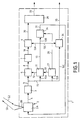
- Figure 1 is the block diagram of a synthetic radar opening according to the invention.
- Figure 2 illustrates the illumination of a territory by a radar on board an aircraft flying over said territory.
- FIG. 3 is the block diagram of computing means used in the radar according to the invention.
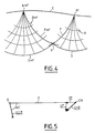
- FIG. 4 illustrates the transposition of data of a coordinate system distance and frequency to an auxiliary reference.
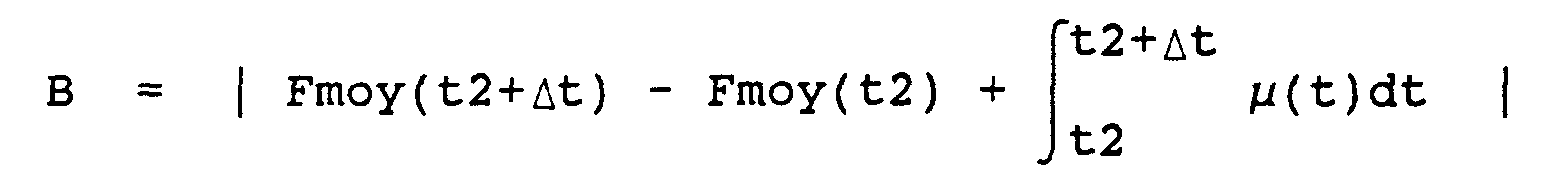
- Figure 5 illustrates the position and speed of a target movable relative to the radar according to the invention.
- the synthetic aperture radar 1 according to the invention and shown diagrammatically in FIG. 1 is mounted on an aircraft A and is used to observe a territory T overflown by said aircraft A (moving at a speed V ), as shown in Figure 2.
- this navigation data is determined by auxiliary means, external to the radar and equipping said aircraft A.
- the synthetic aperture radar 1 according to the invention overcomes these disadvantages.
- said radar 1 comprises, more, computing means 11 for determining, only at from data received from at least some of the above means, for example means 3 in one embodiment particular described below, a Doppler gradient which is representative of said disturbing phase shift existing in said detected signal S2, said calculation means 11 being linked, respectively via a link 12 and of a branch 13A of a connection 13, to said means 5 and 9 to transmit the determined Doppler gradient to them.
- said means 5 and 9 are formed to perform the necessary treatments, only from said Doppler gradient and not from navigation data, as described below.
- the memory 23 transmits, by the link 12 and / or the link 13, like Doppler gradient, the theoretical gradient for which the contrast is the highest.
- Means 5 and 9 use the Doppler gradient as well determined in their treatments, as specified below.
- the means 9 carry out said transposition processing in a simplified way and without use navigation data.
- said auxiliary reference Rref corresponds at the distance and frequency mark at an instant tref (defined in relation to a reference time), and it is defined as a function of the position of aircraft A on its trajectory C at this instant tref.
- said means 9 thus form a radar image of part of the territory overflown.
- the radar 1 comprises means 26 connected to means 11 by a branch 13B of connection 13 and likely to calculate said duration ⁇ t, without using any navigation data, unlike known speed cameras, and transmit said duration ⁇ t to means 2, via a link 31, in order to develop the radar image next.
- the radar 1 includes means 29 which receive the radar images of the means 9 via a link 30, and which determine a radar map which they can transmit to a user device not shown by a link 32.
- said means 27 are formed so as to determine, by more than the above-mentioned average Doppler frequency, also the average scan distance from the radar scan window 1, which allows said analysis window to be centered in order to obtain optimal measurements, likely in particular to be transmitted to the computing means 11 (by a link 33).
- This embodiment therefore makes it possible to increase the precision of the processing carried out.
- said means 27 are of the type of those disclosed in French patent application 95 07199 supra.
- the radar 1 comprises means 34 connected to a branch 15C of the link 15 and capable of determining, moreover, the speed VCM of a moving target CM moving over the observed territory T.
- Said speed VCM is formed by a transverse velocity vt and with a radial speed Vr , as shown in Figure 5 which is a top view, corresponding to the orthogonal projection of the different vectors in the ground plane (with the speed of the aircraft, the nominal speed Vnom ).
- Said means 34 can transmit the speeds as well determined (for example after having transposed them into the OXYZ reference mark) to a non-user device represented by a link 35.
Description
La présente invention concerne un procédé de détection au moyen d'un radar à synthèse d'ouverture, ainsi qu'un radar à synthèse d'ouverture pour la mise en oeuvre de ce procédé.The present invention relates to a detection method using using synthetic aperture radar, as well as opening summary for the implementation of this process.
On sait qu'un radar à synthèse d'ouverture, qui est généralement embarqué à bord d'un aéronef, est particulièrement bien approprié à l'observation de la terre.We know that a synthetic aperture radar, which is generally on board an aircraft, is particularly well suited for earth observation.
De plus, un tel radar présente de très nombreux avantages qui expliquent le grand intérêt et le développement important de ce type de radar, en particulier :
- il peut être utilisé par tout temps ;
- il présente un encombrement réduit ; et
- ses traitements sont peu dépendants de la distance d'observation.
- it can be used in any weather;
- it has a reduced bulk; and
- its treatments are not very dependent on the observation distance.
De façon connue, un tel radar à synthèse d'ouverture comporte des moyens pour réaliser successivement les opérations suivantes :
- émettre un rayonnement électromagnétique en direction d'un territoire observé et survolé par l'aéronef porteur dudit radar ;
- détecter un signal correspondant audit rayonnement électromagnétique renvoyé par ledit territoire survolé et observé ;
- effectuer un traitement de détermination de distance, à partir dudit signal détecté ;
- effectuer un traitement de focalisation destiné à corriger un déphasage perturbateur existant dans ledit signal détecté et dû notamment au déplacement dudit radar à synthèse d'ouverture de manière à obtenir un signal corrigé ;
- effectuer un traitement de détermination de fréquence à partir dudit signal corrigé, lesdits traitements de focalisation et de détermination de fréquence pouvant être réalisés simultanément à l'aide d'un "traitement de corrélation" (radar à synthèse d'ouverture en "mode glissant") ; et
- effectuer un traitement de transposition destiné à transposer, dans un repère de référence lié audit territoire observé, les résultats obtenus à partir des opérations précédentes et définis dans un repère de distance et de fréquence lié au radar, de manière à former une image radar définie dans ledit repère de référence lié au territoire observé.
- emit electromagnetic radiation towards a territory observed and overflown by the aircraft carrying said radar;
- detecting a signal corresponding to said electromagnetic radiation returned by said overflown and observed territory;
- perform a distance determination processing, from said detected signal;
- perform a focusing processing intended to correct a disturbing phase shift existing in said detected signal and due in particular to the displacement of said synthetic aperture radar so as to obtain a corrected signal;
- carry out a frequency determination processing from said corrected signal, said focusing and frequency determination treatments being able to be carried out simultaneously using a "correlation processing" (synthetic aperture radar in "sliding mode") ); and
- perform a transposition processing intended to transpose, in a reference frame linked to said observed territory, the results obtained from the previous operations and defined in a distance and frequency frame linked to the radar, so as to form a radar image defined in said reference benchmark linked to the territory observed.
Toutefois, un tel radar à synthèse d'ouverture présente l'inconvénient que certaines des opérations citées précédemment, notamment le traitement de focalisation et le traitement de transposition, nécessitent pour leur mise en oeuvre des données de navigation relatives à l'aéronef porteur dudit radar.However, such a synthetic aperture radar has the disadvantage that some of the operations mentioned above, including focusing processing and processing for transposition, require for their implementation navigation data relating to the carrier aircraft of said radar.
Ces données de navigation sont déterminées par des capteurs auxiliaires, intégrés généralement dans une centrale inertielle montée à bord dudit aéronef.This navigation data is determined by sensors auxiliaries, generally integrated in an inertial unit boarded said aircraft.
Le radar à synthèse d'ouverture est donc dépendant dans son fonctionnement de moyens externes, et ses mesures peuvent par conséquent être faussées par des erreurs de mesure et/ou des dysfonctionnements de ces moyens externes.Synthetic aperture radar is therefore dependent in its functioning of external means, and its measures can therefore be distorted by measurement errors and / or dysfunctions of these external means.
De plus, l'utilisation d'une centrale inertielle présente de nombreux désavantages, en particulier :
- un coût élevé,
- un encombrement important, et
- une fiabilité parfois réduite.
- high cost,
- significant bulk, and
- reliability sometimes reduced.
La présente invention a pour objet de remédier à ces inconvénients. Elle concerne un procédé de détection au moyen d'un radar à synthèse d'ouverture, susceptible d'être mis en oeuvre sans utiliser de données de navigation relatives à l'aéronef porteur dudit radar, donc de façon complètement indépendante de capteurs auxiliaires et le cas échéant d'une centrale inertielle.The object of the present invention is to remedy these drawbacks. It relates to a detection method using a synthetic aperture radar, capable of being work without using navigation data relating to the aircraft carrying said radar, so completely independent of auxiliary sensors and if necessary of a inertial unit.
A cet effet, selon l'invention, ledit procédé présentant les opérations successives précitées est remarquable en ce que :
- on détermine, à l'aide de données obtenues uniquement à partir d'au moins l'une desdites opérations précitées, un gradient Doppler qui est représentatif dudit déphasage perturbateur existant dans le signal détecté ; et
- on utilise le gradient Doppler ainsi déterminé :
- d'une part, lors dudit traitement de focalisation, pour corriger ledit déphasage perturbateur du signal détecté ; et
- d'autre part, lors dudit traitement de transposition, pour déterminer un repère auxiliaire permettant d'effectuer la transposition dudit repère de distance et de fréquence vers ledit repère de référence, par l'intermédiaire dudit repère auxiliaire.
- determining, using data obtained solely from at least one of said operations above, a Doppler gradient which is representative of said disturbing phase shift existing in the detected signal; and
- we use the Doppler gradient thus determined:
- on the one hand, during said focusing processing, to correct said disturbing phase shift of the detected signal; and
- on the other hand, during said transposition processing, to determine an auxiliary coordinate system allowing the transposition of said distance and frequency coordinate system to said reference coordinate system, via said auxiliary coordinate system.
Ainsi, les traitements nécessitant usuellement des données de navigation, à savoir le traitement de focalisation et le traitement de transposition, sont réalisés selon l'invention en utilisant des données déterminées directement par ledit radar.Thus, the treatments usually requiring data navigation, namely focus processing and transposition processing, are carried out according to the invention using data determined directly by said radar.
Par conséquent, le radar à synthèse d'ouverture mettant en oeuvre le procédé conforme à l'invention est complètement indépendant de moyens externes, notamment d'une centrale inertielle, ce qui permet de remédier aux inconvénients précités.Therefore, synthetic aperture radar highlighting works the process according to the invention is completely independent of external resources, in particular of a central inertial, which overcomes the disadvantages supra.
Dans le cadre de la présente invention, ledit gradient Doppler peut être déterminé de différentes manières. In the context of the present invention, said gradient Doppler can be determined in different ways.
Dans un premier mode de réalisation, pour déterminer ledit gradient Doppler, on effectue, à partir d'un signal détecté et soumis à un traitement de détermination de distance, les opérations suivantes :
- pour une pluralité de gradients théoriques, de valeurs
différentes, choisis arbitrairement, successivement :
- on effectue un traitement de focalisation, en utilisant le gradient théorique choisi ;
- on effectue un traitement de détermination de fréquence ; et
- on mesure le contraste sur une image radar obtenue des traitements précédents, ledit contraste correspondant à l'écart type moyen de l'amplitude du signal détecté sur ladite image radar ;
- on compare les différents contrastes ainsi mesurés ; et
- on choisit, comme gradient Doppler, le gradient théorique pour lequel le contraste est le plus important.
- for a plurality of theoretical gradients, of different values, chosen arbitrarily, successively:
- a focusing treatment is carried out, using the chosen theoretical gradient;
- a frequency determination processing is carried out; and
- the contrast is measured on a radar image obtained from the preceding processing operations, said contrast corresponding to the average standard deviation of the amplitude of the signal detected on said radar image;
- the different contrasts thus measured are compared; and
- the theoretical gradient for which the contrast is the greatest is chosen as the Doppler gradient.
Dans un second mode de réalisation, pour déterminer ledit gradient Doppler µ, on effectue les opérations suivantes :
- on détecte deux signaux, à deux instants différents décalés d'une durée ΔT ;
- pour chacun desdits signaux préalablement soumis à un traitement de distance, on effectue un traitement de détermination de fréquence ;
- on calcule le décalage fréquentiel ΔFd entre les deux images radar obtenues à partir des traitements précédents ; et
- on calcule le gradient Doppler µ à partir de l'expression
:
- two signals are detected, at two different times offset by a duration ΔT;
- for each of said signals previously subjected to a distance processing, a frequency determination processing is carried out;
- the frequency shift ΔFd is calculated between the two radar images obtained from the previous processing; and
- we calculate the Doppler gradient µ from the expression:
De plus, selon l'invention, lors dudit traitement de transposition, pour passer du repère de distance et de fréquence au repère de référence, par l'intermédiaire dudit repère auxiliaire, on effectue les opérations suivantes :
- pour chaque point dudit repère de distance et de fréquence,
présentant une fréquence F et une distance D, on
détermine le point associé de fréquence Fref et de distance
Dref dudit repère auxiliaire, à partir des relations
suivantes :

- µ(t) représente le gradient Doppler déterminé et variant au cours du temps t ;
- tref représente la durée entre un instant de référence prédéterminé et l'instant où le repère de distance et de fréquence correspond au repère auxiliaire ;
- t1 représente la durée entre ledit instant de référence et l'instant de la détection ; et
- λ représente la longueur d'onde du rayonnement électromagnétique émis ; et
- pour chaque point de fréquence Fref et de distance Dref
ainsi déterminé dudit repère auxiliaire, on détermine le
point associé de coordonnées X, Y et Z dudit repère de
référence, à partir des relations suivantes :
dans lesquelles :

- Vnom est la vitesse nominale de l'aéronef ; et
- hnom est l'altitude nominale de l'aéronef.
- for each point of said distance and frequency frame, having a frequency F and a distance D, the associated point of frequency Fref and distance Dref of said auxiliary frame is determined, from the following relationships:
- µ (t) represents the Doppler gradient determined and varying over time t ;
- tref represents the duration between a predetermined reference instant and the instant when the distance and frequency reference corresponds to the auxiliary reference;
- t1 represents the duration between said reference instant and the instant of detection; and
- λ represents the wavelength of the electromagnetic radiation emitted; and
- for each point of frequency Fref and of distance Dref thus determined from said auxiliary reference frame, the associated point of coordinates X, Y and Z of said reference frame is determined, from the following relationships: in which :
- Vnom is the nominal speed of the aircraft; and
- hnom is the nominal altitude of the aircraft.
On notera que l'on utilise la vitesse nominale de l'aéronef, qui est connue, et non la vitesse réelle qui, quant à elle, doit être mesurée par des capteurs appropriés.It will be noted that the nominal speed of the aircraft is used, which is known, not the actual speed which, in turn, must be measured by appropriate sensors.
Le mode de transposition décrit précédemment est particulièrement avantageux, puisque :
- il est complètement indépendant de données de navigation ;
- il peut être mis en oeuvre rapidement et facilement ; et
- il ne nécessite qu'une double transposition de repères, à la différence des méthodes usuelles qui mettent en oeuvre généralement trois transpositions successives.
- it is completely independent of navigation data;
- it can be implemented quickly and easily; and
- it only requires a double transposition of marks, unlike the usual methods which generally implement three successive transpositions.
La présente invention permet également d'estimer la durée Δt entre deux images radar successives, de manière à pouvoir réaliser une carte radar obtenue par la juxtaposition d'une pluralité d'images radar successives.The present invention also makes it possible to estimate the duration Δt between two successive radar images, so that make a radar map obtained by the juxtaposition of a plurality of successive radar images.
Selon l'invention, en supposant que la trajectoire de
l'aéronef porteur du radar est parabolique entre deux images
radar successives, on peut calculer ladite durée Δt, dans un
premier mode de réalisation, à partir de l'expression
simplifiée : Δt = B/ |µ|
dans laquelle :
- µ est le gradient Doppler déterminé ; et
- B est la largeur de la bande de fréquences traitée pour obtenir une image radar.
in which :
- µ is the determined Doppler gradient; and
- B is the width of the frequency band processed to obtain a radar image.
En outre, dans l'hypothèse d'une trajectoire quelconque de
l'aéronef, ladite durée Δt peut être calculée, dans un
second mode de réalisation, à partir de l'expression :

- Fmoy représente la fréquence Doppler moyenne de l'image radar considérée ;
- µ(t) représente le gradient Doppler déterminé et variant au cours du temps t ; et
- t2 représente un temps de référence relatif à l'instant de détection de la première desdites deux images radar considérées.
- Fmoy represents the average Doppler frequency of the radar image considered;
- µ (t) represents the Doppler gradient determined and varying over time t ; and
- t2 represents a reference time relative to the time of detection of the first of said two radar images considered.
Par ailleurs, le procédé conforme à l'invention permet, de plus, de calculer la vitesse d'une cible mobile se déplaçant sur ledit territoire observé.Furthermore, the method according to the invention makes it possible to plus, calculate the speed of a moving moving target on said observed territory.
A cet effet, selon l'invention :
- la vitesse radiale Vr de ladite cible mobile est déterminée
à partir de l'expression :
- Vnom est la vitesse nominale de l'aéronef ;
- λ est la longueur d'onde du rayonnement électromagnétique émis ;
- αc est l'azimut de la cible mobile par rapport à l'aéronef ; et
- Fc est la fréquence Doppler obtenue à partir du rayonnement électromagnétique renvoyé par ladite cible mobile ; et
- la vitesse transversale Vt de ladite cible mobile est
déterminée à partir de l'expression :
- d est la distance entre la cible mobile et le radar ; et
- Δµ est la différence entre le gradient Doppler associé à la cible mobile et celui associé à un point fixe quelconque du territoire observé.
- the radial speed Vr of said moving target is determined from the expression:
- Vnom is the nominal speed of the aircraft;
- λ is the wavelength of the electromagnetic radiation emitted;
- αc is the azimuth of the moving target relative to the aircraft; and
- Fc is the Doppler frequency obtained from the electromagnetic radiation returned by said moving target; and
- the transverse speed Vt of said moving target is determined from the expression:
- d is the distance between the moving target and the radar; and
- Δµ is the difference between the Doppler gradient associated with the moving target and that associated with any fixed point in the observed territory.
La présente invention concerne également un radar à synthèse d'ouverture comportant les moyens mentionnés ci-dessus et destiné à la mise en oeuvre du procédé précité.The present invention also relates to a synthetic radar opening comprising the means mentioned above and intended for the implementation of the above method.
A cet effet, ledit radar à synthèse d'ouverture est remarquable, selon l'invention, en ce qu'il comporte, en plus des moyens précités, des moyens de calcul pour déterminer, uniquement à partir de données reçues desdits moyens précités intégrés dans le radar, un gradient Doppler qui est représentatif dudit déphasage perturbateur existant dans le signal détecté, lesdits moyens de calcul transmettant le gradient Doppler ainsi déterminé auxdits moyens de focalisation et auxdits moyens de transposition pour leurs traitements.To this end, said synthetic aperture radar is remarkable, according to the invention, in that it comprises, in addition to the above-mentioned means, calculation means for determining, only on the basis of data received of the aforementioned means integrated into the radar, a Doppler gradient which is representative of said disturbing phase shift existing in the detected signal, said calculation means transmitting the Doppler gradient thus determined to said focusing means and to said transposition means for their treatments.
En outre, de façon avantageuse, ledit radar peut comporter des moyens pour déterminer la vitesse d'une cible mobile se déplaçant sur le territoire observé, en mettant en oeuvre le procédé de détermination de vitesse spécifié précédemment.In addition, advantageously, said radar may include means for determining the speed of a moving target moving on the observed territory, by implementing the method of determining speed previously specified.
Par ailleurs, dans un mode de réalisation particulièrement avantageux de l'invention, ledit radar comporte de plus des moyens pour déterminer la fréquence Doppler moyenne et la distance d'analyse moyenne de la fenêtre d'analyse dudit radar à synthèse d'ouverture.Furthermore, in a particularly advantageous embodiment of the invention, said radar further comprises means for determining the mean Doppler frequency and the mean analysis distance of the analysis window of said synthetic aperture radar.
Ces moyens présentent, notamment, l'avantage :
- de permettre la détermination de la fréquence Doppler moyenne, notamment en vue d'effectuer un centrage autour de ladite fréquence Doppler moyenne, sans utiliser de données de navigation, à la différence des méthodes généralement utilisées ; et
- de permettre le centrage de la fenêtre d'analyse du radar de manière à obtenir des mesures optimales, utilisées notamment par lesdits moyens de calcul, ce qui permet d'augmenter la précision des traitements réalisés conformément à l'invention.
- to allow the determination of the average Doppler frequency, in particular with a view to centering around said average Doppler frequency, without using navigation data, unlike the methods generally used; and
- allow centering of the radar analysis window so as to obtain optimal measurements, used in particular by said calculation means, which makes it possible to increase the precision of the treatments carried out in accordance with the invention.
Les figures du dessin annexé feront bien comprendre comment l'invention peut être réalisée. Sur ces figures, des références identiques désignent des éléments semblables.The figures in the accompanying drawing will make it clear how the invention can be realized. In these figures, references identical denote similar elements.
La figure 1 est le schéma synoptique d'un radar à synthèse d'ouverture conforme à l'invention.Figure 1 is the block diagram of a synthetic radar opening according to the invention.
La figure 2 illustre l'illumination d'un territoire par un radar embarqué à bord d'un aéronef qui survole ledit territoire.Figure 2 illustrates the illumination of a territory by a radar on board an aircraft flying over said territory.
La figure 3 est le schéma synoptique de moyens de calcul utilisés dans le radar conforme à l'invention.Figure 3 is the block diagram of computing means used in the radar according to the invention.
La figure 4 illustre la transposition de données d'un repère de distance et de fréquence vers un repère auxiliaire.FIG. 4 illustrates the transposition of data of a coordinate system distance and frequency to an auxiliary reference.
La figure 5 illustre la position et la vitesse d'une cible mobile par rapport au radar conforme à l'invention.Figure 5 illustrates the position and speed of a target movable relative to the radar according to the invention.
Le radar à synthèse d'ouverture 1 conforme à l'invention et
représenté schématiquement sur la figure 1 est monté sur un
aéronef A et est utilisé pour observer un territoire T
survolé par ledit aéronef A (se déplaçant à une vitesse
De façon connue, ledit radar à synthèse d'ouverture 1 comporte :
- des moyens 2 pour émettre un rayonnement électromagnétique S1 en direction du territoire survolé T, de manière à illuminer une zone ZI dudit territoire T, comme illustré sur la figure 2 ;
- des moyens 2 pour détecter un signal S2 correspondant
audit rayonnement électromagnétique renvoyé par ladite
zone ZI illuminée.
Lesdits moyens 2 d'émission et de réception sont réalisés, de préférence, sous forme d'un système électronique 2A comportant une antenne 2B d'émission et de réception ; - des moyens 3 reliés par une
liaison 4 auxdits moyens 2 et susceptibles d'effectuer un traitement de détermination de distance, à partir dudit signal détecté S2 ; - des moyens 5 reliés par une
liaison 6 auxdits moyens 3 et susceptibles d'effectuer un traitement de focalisation destiné à corriger un déphasage perturbateur existant dans ledit signal détecté S2 et dû notamment au déplacement dudit radar à synthèse d'ouverture 1 embarqué à bord de l'aéronef A, de manière à obtenir un signal corrigé Sc ; - des moyens 7 reliés par une liaison 8 auxdits moyens 5 et susceptibles d'effectuer un traitement de détermination de fréquence, à partir dudit signal corrigé Sc ; et
- des moyens 9 reliés par une
liaison 10 auxdits moyens 7 et susceptibles d'effectuer un traitement de transposition destiné à transposer, dans un repère de référence OXYZ lié audit territoire T et représenté sur la figure 2, les résultats obtenus à partir des opérations précédentes et définis dans un repère de distance et de fréquence R lié au radar tel que représenté sur la figure 4, de manière à former une image radar définie dans ledit repère de référence OXYZ lié au territoire observé T.
- means 2 for emitting electromagnetic radiation S1 in the direction of the territory overflown T, so as to illuminate an area ZI of said territory T, as illustrated in FIG. 2;
- means 2 for detecting a signal S2 corresponding to said electromagnetic radiation returned by said illuminated zone ZI. Said transmission and reception means 2 are preferably produced in the form of an
electronic system 2A comprising anantenna 2B for transmission and reception; - means 3 connected by a
link 4 to saidmeans 2 and capable of carrying out a distance determination processing, from said detected signal S2; - means 5 connected by a
link 6 to saidmeans 3 and capable of performing a focusing treatment intended to correct a disturbing phase shift existing in said detected signal S2 and due in particular to the displacement of said synthetic aperture radar 1 on board the aircraft A, so as to obtain a corrected signal Sc; - means 7 connected by a link 8 to said
means 5 and capable of performing frequency determination processing, from said corrected signal Sc; and - means 9 connected by a
link 10 to saidmeans 7 and capable of carrying out a transposition processing intended to transpose, into an OXYZ reference frame linked to said territory T and represented in FIG. 2, the results obtained from the previous operations and defined in a distance and frequency reference frame R linked to the radar as shown in FIG. 4, so as to form a radar image defined in said reference frame OXYZ linked to the observed territory T.
On sait que les radars à synthèse d'ouverture connus utilisent
des données de navigation de l'aéronef A porteur du
radar pour effectuer certains traitements, et notamment les
traitements mis en oeuvre par lesdits moyens 5 et 9. We know that known synthetic aperture radars use
navigation data of aircraft A carrying the
radar to perform certain treatments, including
treatments implemented by said
De façon connue, ces données de navigation sont déterminées par des moyens auxiliaires, externes au radar et équipant ledit aéronef A.In a known manner, this navigation data is determined by auxiliary means, external to the radar and equipping said aircraft A.
Ceci présente l'inconvénient important que les radars connus sont dépendants de ces moyens auxiliaires et les résultats de la détection peuvent donc être faussés par des erreurs de mesure et/ou des dysfonctionnements de ces moyens auxiliaires.This has the significant drawback that known radars are dependent on these aids and the results of the detection can therefore be distorted by errors of measurement and / or malfunctions of these auxiliary means.
Le radar à synthèse d'ouverture 1 conforme à l'invention permet de remédier à ces inconvénients.The synthetic aperture radar 1 according to the invention overcomes these disadvantages.
A cet effet, selon l'invention, ledit radar 1 comporte, de
plus, des moyens de calcul 11 pour déterminer, uniquement à
partir de données reçues d'au moins certains moyens précédents,
par exemple des moyens 3 dans un mode de réalisation
particulier décrit ci-dessous, un gradient Doppler qui est
représentatif dudit déphasage perturbateur existant dans
ledit signal détecté S2, lesdits moyens de calcul 11 étant
reliés, respectivement par l'intermédiaire d'une liaison 12
et d'une branche 13A d'une liaison 13, auxdits moyens 5 et 9
pour leur transmettre le gradient Doppler déterminé. Selon
l'invention, lesdits moyens 5 et 9 sont formés pour effectuer
les traitements nécessaires, uniquement à partir dudit
gradient Doppler et non à partir de données de navigation,
de la manière décrite ci-dessous.To this end, according to the invention, said radar 1 comprises,
more, computing means 11 for determining, only at
from data received from at least some of the above means,
for example means 3 in one embodiment
particular described below, a Doppler gradient which is
representative of said disturbing phase shift existing in
said detected signal S2, said calculation means 11 being
linked, respectively via a
Dans un mode de réalisation particulièrement avantageux de l'invention, pour déterminer ledit gradient Doppler µ, les moyens de calcul 11 effectuent successivement les opérations :
- ils détectent deux signaux S2, à deux instants différents décalés d'une durée ΔT ;
- pour chacun desdits signaux préalablement soumis à un traitement de distance, ils effectuent un traitement de détermination de fréquence ;
- ils calculent le décalage fréquentiel ΔFd entre les deux images radar obtenues à partir des traitements précédents ; et
- ils calculent le gradient Doppler µ à partir de l'expression : µ = ΔFd / ΔT.
- they detect two signals S2, at two different times offset by a duration ΔT;
- for each of said signals previously subjected to a distance processing, they perform a frequency determination processing;
- they calculate the frequency shift ΔFd between the two radar images obtained from the previous processing; and
- they calculate the Doppler gradient µ from the expression: µ = ΔFd / ΔT.
Dans un autre mode de réalisation avantageux de l'invention, lesdits moyens de calcul 11 comportent, tel que représenté sur la figure 3 :
- un élément de calcul 14 qui est relié par une branche
15A d'une liaison 15 à laliaison 6, c'est-à-dire à la sortie des moyens 3, et qui effectue, à partir des informations reçues desdits moyens 3, des traitements de focalisation précisés ci-dessous, en utilisant à chaque fois l'un d'une pluralité de gradients théoriques, de valeurs différentes, choisis arbitrairement et reçus par uneliaison 16. Ledit élément de calcul 14 peut correspondre aux moyens 5 précités ou il peut représenter un élément de calcul indépendant, travaillant selon le même principe que lesdits moyens 5 ; - un élément de calcul 17 relié par une
liaison 18 à l'élément de calcul 14 et effectuant des traitements de détermination de fréquence. De même, ledit élément de calcul 17 peut correspondre aux moyens 7 précités ou il peut représenter un élément de calcul indépendant, travaillant selon le même principe que lesdits moyens 7 ; - un élément de calcul 19 relié par une
liaison 20 à l'élément de calcul 17 et déterminant le contraste sur une image formée et transmise par l'élément de calcul 17, ledit contraste correspondant à l'écart-type moyen de l'amplitude du signal détecté sur ladite image ; un comparateur 21 comparant le contraste déterminé par l'élément de calcul 19 et transmis par uneliaison 22, à un contraste enregistré dans une mémoire 23 et reçu par uneliaison 24 ; et- ladite mémoire 23 :
- qui enregistre à chaque fois la valeur du contraste la
plus élevée des valeurs comparées par le comparateur 21,
reçue par une
liaison 25, ainsi que le gradient théorique correspondant ; et - qui transmet au comparateur 21 par
la liaison 24 pour une comparaison suivante la valeur du contraste ainsi enregistrée.
- qui enregistre à chaque fois la valeur du contraste la
plus élevée des valeurs comparées par le comparateur 21,
reçue par une
- a
computing element 14 which is connected by abranch 15A of alink 15 to thelink 6, that is to say at the output of themeans 3, and which performs, from the information received from said means 3, focusing treatments specified below, each time using one of a plurality of theoretical gradients, of different values, chosen arbitrarily and received by alink 16. Saidcalculation element 14 may correspond to theaforementioned means 5 or it may represent an independent calculation element, working according to the same principle as said means 5; - a
calculation element 17 connected by alink 18 to thecalculation element 14 and performing frequency determination treatments. Likewise, saidcalculation element 17 can correspond to theaforementioned means 7 or it can represent an independent calculation element, working according to the same principle as said means 7; - a
calculation element 19 connected by alink 20 to thecalculation element 17 and determining the contrast on an image formed and transmitted by thecalculation element 17, said contrast corresponding to the average standard deviation of the amplitude of the signal detected on said image; - a
comparator 21 comparing the contrast determined by thecalculation element 19 and transmitted by alink 22, to a contrast recorded in amemory 23 and received by alink 24; and - said memory 23:
- which records each time the value of the highest contrast of the values compared by the
comparator 21, received by alink 25, as well as the corresponding theoretical gradient; and - which transmits to the
comparator 21 via thelink 24 for a next comparison the value of the contrast thus recorded.
- which records each time the value of the highest contrast of the values compared by the
Lorsque les traitements définis précédemment ont été réalisés
pour tous les gradients théoriques choisis arbitrairement,
la mémoire 23 transmet, par la liaison 12 et/ou la
liaison 13, comme gradient Doppler, le gradient théorique
pour lequel le contraste est le plus élevé.When the treatments defined above have been carried out
for all the theoretical gradients chosen arbitrarily,
the
Les moyens 5 et 9 utilisent le gradient Doppler ainsi
déterminé dans leurs traitements, tel que précisé ci-dessous.
A cet effet, on rappellera, tout d'abord, que pour un rayonnement électromagnétique émis S1, le radar détecte un signal S2 de phase (t), telle que (t) = o + 2.π.F.t + π.µ.t2, dans laquelle :
- o est la phase du signal à un instant de référence de la détection ;
- F est la fréquence Doppler caractéristique de la position angulaire d'un point P correspondant du territoire observé T par rapport au radar 1 ; et
- µ est le gradient Doppler qui engendre un déphasage perturbateur π.µ.t2 dû au déplacement dudit radar 1 par rapport audit point P.
- o is the phase of the signal at a reference instant of detection;
- F is the Doppler frequency characteristic of the angular position of a point P corresponding to the observed territory T with respect to the radar 1; and
- µ is the Doppler gradient which generates a disturbing phase shift π.µ.t 2 due to the displacement of said radar 1 relative to said point P.
Pour corriger ce déphasage perturbateur, qui entraíne
notamment un flou dans l'image obtenue, les moyens 5
déterminent, lors du traitement de focalisation, un signal
corrigé Sc(t) à partir de l'expression :
- S2(t) le signal capté et reçu des moyens 3 ; et
- µ le gradient Doppler déterminé par les moyens de calcul 11, comme indiqué précédemment.
- S2 (t) the signal received and received from the
means 3; and - µ the Doppler gradient determined by the calculation means 11, as indicated above.
On notera que les radars à synthèse d'ouverture connus effectuent cette focalisation, c'est-à-dire la correction dudit déphasage perturbateur, en utilisant des données de navigation, à savoir généralement la vitesse et l'accélération radiale de l'aéronef porteur du radar, ce qui n'est pas le cas dans la présente invention.Note that known aperture synthesis radars focus, i.e. correct of said disturbing phase shift, using data from navigation, usually speed and acceleration radial of the aircraft carrying the radar, which is not the case in the present invention.
Quant au traitement de transposition précité, il est réalisé dans les radars connus, en effectuant successivement à l'aide de données de navigation trois transpositions non représentées, à savoir :
- d'abord, dudit repère de distance et de fréquence lié au radar vers un repère orthonormé local, en utilisant notamment la vitesse de l'aéronef ;
- ensuite, dudit repère orthonormé local vers un repère géographique local ; et
- enfin, dudit repère géographique local vers ledit repère de référence lié au territoire survolé.
- first, from said distance and frequency reference linked to the radar to a local orthonormal reference, using in particular the speed of the aircraft;
- then from said local orthonormal benchmark to a local geographic benchmark; and
- finally, from said local geographic reference point to said reference reference point linked to the territory overflown.
Conformément à l'invention, les moyens 9 effectuent ledit
traitement de transposition de façon simplifiée et sans
utiliser de données de navigation.According to the invention, the
Pour ce faire, lesdits moyens 9 réalisent :
- d'abord, une transposition du repère de distance et de fréquence R représenté sur la figure 4, vers un repère auxiliaire Rref également représenté sur cette figure 4 ; et
- ensuite, une transposition dudit repère auxiliaire Rref vers ledit repère de référence OXYZ lié à un point O dudit territoire T, comme représenté sur la figure 2.
- first, a transposition of the distance and frequency reference frame R shown in FIG. 4, to an auxiliary reference frame Rref also shown in this figure 4; and
- then, a transposition of said auxiliary reference frame Rref to said reference reference frame OXYZ linked to a point O of said territory T, as shown in FIG. 2.
Selon l'invention, ledit repère auxiliaire Rref correspond au repère de distance et de fréquence à un instant tref (défini par rapport à un temps de référence), et il est défini en fonction de la position de l'aéronef A sur sa trajectoire C à cet instant tref.According to the invention, said auxiliary reference Rref corresponds at the distance and frequency mark at an instant tref (defined in relation to a reference time), and it is defined as a function of the position of aircraft A on its trajectory C at this instant tref.
Pour expliciter le mode de mise en oeuvre de l'invention, on utilise un repère de distance et de fréquence R quelconque relatif à une position A1 de l'aéronef A sur sa trajectoire C à un instant t1 (également défini par rapport audit temps de référence).To explain the mode of implementation of the invention, we uses any distance and frequency mark R relating to a position A1 of the aircraft A on its trajectory C at an instant t1 (also defined with respect to said time reference).
Selon l'invention, pour réaliser la première des deux
transpositions précitées, on détermine, pour chaque point P
de distance D et de fréquence F du repère R, les coordonnées
correspondantes (distance Dref et fréquence Fref) dudit
point P dans le repère Rref, à partir des relations suivantes
:

- µ(t) représente le gradient Doppler déterminé et variant au cours du temps t ; et
- λ représente la longueur d'onde du rayonnement électromagnétique S1 émis.
- µ (t) represents the Doppler gradient determined and varying over time t ; and
- λ represents the wavelength of the electromagnetic radiation S1 emitted.
Ensuite, pour passer dudit repère Rref vers le repère de
référence OXYZ, les moyens 9 déterminent, pour chaque point
P (de distance Dref et de fréquence Fref) ainsi caractérisé,
ses coordonnées X, Y et Z dans ledit repère de référence
OXYZ, à partir des relations suivantes :

- Vnom est la vitesse nominale de l'aéronef A ; et
- hnom est l'altitude nominale de l'aéronef A.
- Vnom is the nominal speed of the aircraft A; and
- hnom is the nominal altitude of aircraft A.
Comme indiqué précédemment, lesdits moyens 9 forment ainsi une image radar d'une partie du territoire survolé.As indicated above, said means 9 thus form a radar image of part of the territory overflown.
De façon connue, pour réaliser une carte radar qui est obtenue par la juxtaposition d'une pluralité de telles images radar, généralement réalisées sous forme de bandes imagées, il est nécessaire de connaítre la durée réelle Δt entre deux images radar successives, pour pouvoir effectuer une juxtaposition précise.In known manner, to produce a radar map which is obtained by the juxtaposition of a plurality of such radar images, usually taken in the form of bands pictorial, it is necessary to know the real duration Δt between two successive radar images, to be able to perform a precise juxtaposition.
Selon l'invention, le radar 1 comporte des moyens 26 reliés
aux moyens 11 par une branche 13B de la liaison 13 et
susceptibles de calculer ladite durée Δt, sans utiliser de
données de navigation, au contraire des radars connus, et de
transmettre ladite durée Δt aux moyens 2, par l'intermédiaire
d'une liaison 31, afin d'élaborer l'image radar
suivante.According to the invention, the radar 1 comprises means 26 connected
to means 11 by a
A cet effet, lesdits moyens 26 déterminent ladite durée Δt :
- dans un premier mode de réalisation, en supposant que la
trajectoire C de l'aéronef A est parabolique entre les
deux images radar successives considérées, à partir de
l'expression simplifiée Δt = B/|µ|
dans laquelle :- µ est le gradient Doppler déterminé ; et
- B est la largeur de la bande de fréquences traitée pour obtenir une image radar ; et
- dans un second mode de réalisation, pour une trajectoire C
quelconque de l'aéronef A, à partir de l'expression :
dans laquelle :
- Fmoy représente une fréquence Doppler moyenne de l'image
radar considérée, qui est déterminée par des moyens 27
précisés ci-dessous et qui est transmise aux moyens 26
par une liaison 28 ; - µ(t) représente le gradient Doppler déterminé et variant au cours du temps t ; et
- t2 représente un temps de référence relatif à l'instant de détection de la première desdites deux images radar.
- in a first embodiment, assuming that the trajectory C of the aircraft A is parabolic between the two successive radar images considered, from the simplified expression Δt = B / | µ |
in which :- µ is the determined Doppler gradient; and
- B is the width of the frequency band processed to obtain a radar image; and
- in a second embodiment, for any trajectory C of the aircraft A, from the expression: in which :
- Fmoy represents an average Doppler frequency of the radar image considered, which is determined by
means 27 specified below and which is transmitted to themeans 26 by alink 28; - µ (t) represents the Doppler gradient determined and varying over time t ; and
- t2 represents a reference time relative to the instant of detection of the first of said two radar images.
Par ailleurs, le radar 1 comporte des moyens 29 qui reçoivent
les images radar des moyens 9 par l'intermédiaire d'une
liaison 30, et qui déterminent une carte radar qu'ils
peuvent transmettre à un dispositif utilisateur non représenté
par une liaison 32.Furthermore, the radar 1 includes
Dans un mode de réalisation avantageux de l'invention, lesdits moyens 27 sont formés de manière à déterminer, en plus de la fréquence Doppler moyenne précitée, également la distance d'analyse moyenne de la fenêtre d'analyse du radar 1, ce qui permet de centrer ladite fenêtre d'analyse de manière à obtenir des mesures optimales, susceptibles notamment d'être transmises aux moyens de calcul 11 (par une liaison 33). Ce mode de réalisation permet donc d'augmenter la précision des traitement effectués.In an advantageous embodiment of the invention, said means 27 are formed so as to determine, by more than the above-mentioned average Doppler frequency, also the average scan distance from the radar scan window 1, which allows said analysis window to be centered in order to obtain optimal measurements, likely in particular to be transmitted to the computing means 11 (by a link 33). This embodiment therefore makes it possible to increase the precision of the processing carried out.
De préférence, lesdits moyens 27 sont du type de ceux divulgués dans la demande de brevet français 95 07199 précitée.Preferably, said means 27 are of the type of those disclosed in French patent application 95 07199 supra.
Par ailleurs, le radar 1 comporte des moyens 34 reliés à une
branche 15C de la liaison 15 et susceptibles de déterminer,
de plus, la vitesse
Ladite vitesse
Selon l'invention, les moyens 34 déterminent :
- ladite vitesse radiale Vr, à partir de l'expression :
- λ est la longueur d'onde du rayonnement électromagnétique
S1
émis par l'antenne 2B ; - αc est l'azimut de la cible mobile CM par rapport audit radar 1 ; et
- Fc est la fréquence Doppler obtenue à partir du rayonnement électromagnétique S2 renvoyé par ladite cible mobile CM ; et
- λ est la longueur d'onde du rayonnement électromagnétique
S1
- ladite vitesse transversale Vt, à partir de l'expression :
- d est la distance entre la cible mobile CM et le radar 1 (ou l'aéronef A) ; et
- Δµ est la différence entre le gradient Doppler associé à la cible mobile CM et celui associé à un point fixe quelconque du territoire observé, par exemple le point P d'azimut α de la figure 1.
- said radial speed Vr, from the expression:
- λ is the wavelength of the electromagnetic radiation S1 emitted by the
antenna 2B; - αc is the azimuth of the moving target CM with respect to said radar 1; and
- Fc is the Doppler frequency obtained from the electromagnetic radiation S2 returned by said moving target CM; and
- λ is the wavelength of the electromagnetic radiation S1 emitted by the
- said transverse speed Vt, from the expression:
- d is the distance between the moving target CM and the radar 1 (or the aircraft A); and
- Δµ is the difference between the Doppler gradient associated with the moving target CM and that associated with any fixed point in the observed territory, for example the point P of azimuth α in Figure 1.
Lesdits moyens 34 peuvent transmettre les vitesses ainsi
déterminées (par exemple après les avoir transposées dans le
repère de référence OXYZ) à un dispositif utilisateur non
représenté, par une liaison 35.Said means 34 can transmit the speeds as well
determined (for example after having transposed them into the
OXYZ reference mark) to a non-user device
represented by a
Claims (8)
- Detection method, using a synthetic aperture radar (1) on board an aircraft (A) and observing an overflown territory (T), wherein the following operations are effected:characterised in that:electromagnetic radiation (S1) is transmitted towards said overflown territory (T);a signal (S2) corresponding to said electromagnetic radiation reflected by said overflown territory is detected;a distance determination processing operation is carried out on said detected signal (S2);a focusing processing operation is carried out to correct an unwanted phase-shift in said detected signal and due notably to the displacement of said synthetic aperture radar, in order to obtain a corrected signal;a frequency determination processing operation is carried out on said corrected signal; anda transposition processing operation is carried out in order to transpose, into a reference frame of reference (OXYZ) tied to said observed territory, the results obtained from the previous operations and defined in a distance and frequency frame of reference (R) tied to the radar (1), in order to form a radar image defined in said reference frame of reference (OXYZ) tied to the observed territory,using data obtained exclusively from at least one of the preceding operations, a Doppler gradient is determined that is representative of said unwanted phase-shift in the detected signal; andthe Doppler gradient determined in this way is used:on the one hand, during said focusing processing operation, to correct said unwanted phase-shift of the detected signal (S2); andon the other hand, during said transposition processing operation, to determine an auxiliary frame of reference (Rref) enabling the transposition from said distance and frequency frame of reference (R) to said reference frame of reference (OXYZ) by way of said auxiliary frame of reference (Rref) andduring said transposition processing operation, in order to transpose from the distance and frequency frame of reference (R) to the reference frame of reference (OXYZ) by way of said auxiliary frame of reference (Rref), the following operations are carried out:for each point (P) of said distance and frequency frame of reference (R), having a frequency F and a distance D, the associated point having a frequency Fref and a distance Dref of said auxiliary frame of reference (Rref) is determined from the following equations:in which :
 µ(t) represents the Doppler gradient determined and varying with time t;tref represents the time between a predetermined reference time and the time at which the distance and frequency frame of reference corresponds to the auxiliary frame of reference;t1 represents the time between said reference time and the detection time; andλ represents the wavelength of the electromagnetic radiation (S1) transmitted; andfor each point having a frequency Fref and a distance Dref determined in this way of said auxiliary frame of reference (Rref), the associated point with coordinates X, Y and Z of said reference frame of reference (OXYZ) is determined from the following equations:Vnom is the nominal speed of the aircraft (A); andhnom is the nominal altitude of the aircraft (A).
 - Method according to claim 1,
characterised in that, in order to determine said Doppler gradient, the following operations are carried out on a detected signal subjected to a distance determination processing operation:successively for a plurality of different theoretical gradient values chosen arbitrarily:a focusing processing operation is carried out using the chosen theoretical gradient;a frequency determination processing operation is carried out; andthe contrast is measured on a radar image obtained from the previous processing operations, said contrast corresponding to the mean standard deviation of the amplitude of the detected signal over said radar image;the various contrasts measured in this way are compared; andthe Doppler gradient chosen is the theoretical gradient for which the contrast is the highest. - Method according to claim 1,
characterised in that, in order to determine said Doppler gradient µ, the following operations are carried out:two signals (S2) are detected at two different times separated by a time ΔT;for each of said signals previously subjected to a distance processing operation, a Doppler frequency determination processing operation is carried out;the frequency shift ΔFd between the two radar signals obtained from the previous processing operations is calculated; andthe Doppler gradient µ is calculated from the expression: - Method according to any one of the preceding claims for estimating the time Δt between two successive radar images in order to be able to form a radar map by juxtaposing a plurality of successive radar images,
characterised in that the trajectory of the aircraft is parabolic between said two successive radar images and in that said time Δt is calculated from the simplified expression: Δt = B/|µ|
in which:µ is the Doppler gradient determined; andB is the width of the frequency band processed to obtain a radar image. - Method according to any one of claims 1 to 3, for estimating the time Δt between two successive radar images, in order to be able to form a radar map by juxtaposing a plurality of successive radar images,
characterised in that said time Δt is calculated from the expression:in which: B represents the width of the band of frequencies processed to obtain a radar image;Fmoy represents the mean Doppler frequency of the radar image considered;µ(t) represents the Doppler gradient determined and varying with time t; andt2 represents a reference time relating to the time of detection of the first of said two radar images considered.
 - Method according to any one of the preceding claims, enabling additional calculation of the speed of a mobile target (CM) moving over said observed territory,
characterised in that:the radial speed Vr of said mobile target (CM) is determined from the expression:Vnom is the nominal speed of the aircraft (A);λ is the wavelength of the electromagnetic radiation (S1) transmitted;αc is the azimuth of the mobile target (CM) relative to the aircraft (A); andFc is the Doppler frequency obtained from the electromagnetic radiation (S2) reflected by said mobile target (CM); andthe transverse speed Vt of said mobile target (CM) is determined from the expression:d is the distance between the mobile target (CM) and the radar; andΔµ is the difference between the Doppler gradient associated with the mobile target and that associated with any fixed point of the observed territory. - Synthetic aperture radar for implementing the method specified in any one of claims 1 through 6, including:characterised in that it further includes calculation means (11) for determining, exclusively from data received from the preceding means, a Doppler gradient that is representative of said unwanted phase-shift in the detected signal (S2), said calculation means (11) transmitting the Doppler gradient determined to said focusing means (5) and to said transposition means (9) for processing, and in that said transposition means (9) effect transposition by means of an auxiliary frame of reference (Rref) which is determined using said Doppler gradient.means (2) for transmitting electromagnetic radiation (S1) towards a territory (T) overflown by the aircraft (A) carrying said radar;means (2) for detecting a signal (S2) corresponding to said electromagnetic radiation reflected by said overflown and observed territory;means (3) for carrying out a distance determination processing operation using said detected signal (S2);means (5) for carrying out a focusing processing operation to correct an unwanted phase-shift in said detected signal (S2) and due notably to the displacement of said synthetic aperture radar, in order to obtain a corrected signal;means (7) for carrying out a frequency determination processing operation on said corrected signal; andmeans (9) for carrying out a transposition processing operation in order to transpose into a reference frame of reference (OXYZ) tied to said observed territory (T) the results obtained from the previous operations and defined in a distance and frequency frame of reference (R) tied to the radar, in order to form a radar image defined in said reference frame of reference (OXYZ) tied to the observed territory,
- Synthetic aperture radar according to claim 7,
characterised in that it includes means (34) for determining the speed of a mobile target (CM) moving across the observed territory using the method specified in claim 6.
Applications Claiming Priority (2)
| Application Number | Priority Date | Filing Date | Title |
|---|---|---|---|
| FR9514555 | 1995-12-08 | ||
| FR9514555A FR2742233B1 (en) | 1995-12-08 | 1995-12-08 | DETECTION METHOD USING RADAR AND RADAR FOR CARRYING OUT SAID METHOD |
Publications (2)
| Publication Number | Publication Date |
|---|---|
| EP0778471A1 EP0778471A1 (en) | 1997-06-11 |
| EP0778471B1 true EP0778471B1 (en) | 2002-01-02 |
Family
ID=9485296
Family Applications (1)
| Application Number | Title | Priority Date | Filing Date |
|---|---|---|---|
| EP96402522A Expired - Lifetime EP0778471B1 (en) | 1995-12-08 | 1996-11-22 | Radar detection method and system |
Country Status (5)
| Country | Link |
|---|---|
| EP (1) | EP0778471B1 (en) |
| DE (1) | DE69618328T2 (en) |
| ES (1) | ES2171633T3 (en) |
| FR (1) | FR2742233B1 (en) |
| IL (1) | IL119704A (en) |
Families Citing this family (3)
| Publication number | Priority date | Publication date | Assignee | Title |
|---|---|---|---|---|
| US7106243B2 (en) * | 2004-11-23 | 2006-09-12 | Raytheon Company | Technique for enhanced quality high resolution 2D imaging of ground moving targets |
| GB2425905B (en) * | 2005-05-07 | 2009-09-30 | Sula Systems Ltd | Method for resolving ambiguity in the detection and location of moving targets in synthetic aperture radar |
| ITMI20112428A1 (en) * | 2011-12-29 | 2013-06-30 | Selex Galileo Spa | RADAR EQUIPMENT FOR SYNTHETIC OPENING AND METHOD FOR THE PRODUCTION OF RADAR IMAGES FOR SYNTHETIC OPENING OF MOVING OBJECTS |
Family Cites Families (1)
| Publication number | Priority date | Publication date | Assignee | Title |
|---|---|---|---|---|
| GB8714746D0 (en) * | 1987-06-24 | 1987-07-29 | Secr Defence | Synthetic aperture radar |
-
1995
- 1995-12-08 FR FR9514555A patent/FR2742233B1/en not_active Expired - Fee Related
-
1996
- 1996-11-22 ES ES96402522T patent/ES2171633T3/en not_active Expired - Lifetime
- 1996-11-22 DE DE69618328T patent/DE69618328T2/en not_active Expired - Fee Related
- 1996-11-22 EP EP96402522A patent/EP0778471B1/en not_active Expired - Lifetime
- 1996-11-27 IL IL11970496A patent/IL119704A/en not_active IP Right Cessation
Also Published As
| Publication number | Publication date |
|---|---|
| FR2742233A1 (en) | 1997-06-13 |
| EP0778471A1 (en) | 1997-06-11 |
| IL119704A0 (en) | 1997-02-18 |
| DE69618328D1 (en) | 2002-02-07 |
| DE69618328T2 (en) | 2002-08-14 |
| IL119704A (en) | 2001-04-30 |
| ES2171633T3 (en) | 2002-09-16 |
| FR2742233B1 (en) | 1998-02-06 |
Similar Documents
| Publication | Publication Date | Title |
|---|---|---|
| EP2122388B1 (en) | Device and method for locating a mobile approaching a surface reflecting electromagnetic waves | |
| FR2517435A1 (en) | MISSILE GUIDING SYSTEM WITH CARD EQUALIZER HORIZONTAL AND VERTICAL BRAND CONTROL | |
| EP0658775B1 (en) | Anticollision device for automotive vehicle | |
| EP2574957B1 (en) | Method for estimating the unambiguous Doppler frequency of a moving target, in particular marine, and radar implementing said method | |
| FR2648570A1 (en) | DEVICE AND METHOD FOR MEASURING THE AZIMUT AND THE SITE OF AN OBJECT | |
| EP2469299B1 (en) | Method for enhancing images acquired by a radar with synthetic aperture | |
| EP0568426A1 (en) | Method and device for detection and localisation of objects on a relatively level surface | |
| FR2722302A1 (en) | METHOD FOR DETECTING, LOCATING AND DETERMINING THE SPEED OF MOBILE TARGETS FROM RAW RADAR DATA OF A COHERENT IMAGING SYSTEM | |
| EP0716317B1 (en) | Device for the detection and location of ground objects | |
| EP2344901B1 (en) | Method of determining the direction of arrival of an electromagnetic wave | |
| EP0778471B1 (en) | Radar detection method and system | |
| EP2544020B1 (en) | Method and device for detecting a target masked by high-energy reflectors | |
| EP1227333A1 (en) | Method and device to locate a ground-based emitter from a satellite | |
| EP1324065B1 (en) | Method for passively finding the position of a target and especially for air-air locating | |
| FR2632420A1 (en) | METHOD AND APPARATUS FOR COMPENSATING FOR SCALE SPEED IN COHERENT DOPPLER RADAR WITH VARIABLE AMBIGE SPEED | |
| US6586748B1 (en) | Non-invasive water current measurement system and method | |
| EP4004597B1 (en) | Coherent lidar imaging method and associated lidar | |
| EP0881505B1 (en) | Method of repeated position-finding for a mobile object using radar cartographie of uneven terrain | |
| EP3859882A1 (en) | Radioelectric system with multiple antenna networks and with adaptive waveforms | |
| EP0524099A1 (en) | Method and device for airborne navigation and collision avoidance | |
| FR2545613A1 (en) | APPARATUS FOR MEASURING THE SPEED OF AN OBJECT, IN PARTICULAR AN AIRCRAFT | |
| FR2684767A1 (en) | Synthetic aperture radar | |
| EP0818692A1 (en) | Method for determining the absolute value of the velocity of a radar carrier | |
| WO2010001035A2 (en) | Method and device for estimating at least one speed component of a moving target | |
| EP0720028A1 (en) | Multifunctional, inconspicuous distance measuring apparatus |
Legal Events
| Date | Code | Title | Description |
|---|---|---|---|
| PUAI | Public reference made under article 153(3) epc to a published international application that has entered the european phase |
Free format text: ORIGINAL CODE: 0009012 |
|
| AK | Designated contracting states |
Kind code of ref document: A1 Designated state(s): BE CH DE ES GB IT LI NL |
|
| 17P | Request for examination filed |
Effective date: 19970626 |
|
| 17Q | First examination report despatched |
Effective date: 20000327 |
|
| RAP1 | Party data changed (applicant data changed or rights of an application transferred) |
Owner name: AEROSPATIALE MATRA |
|
| GRAG | Despatch of communication of intention to grant |
Free format text: ORIGINAL CODE: EPIDOS AGRA |
|
| GRAG | Despatch of communication of intention to grant |
Free format text: ORIGINAL CODE: EPIDOS AGRA |
|
| GRAH | Despatch of communication of intention to grant a patent |
Free format text: ORIGINAL CODE: EPIDOS IGRA |
|
| GRAH | Despatch of communication of intention to grant a patent |
Free format text: ORIGINAL CODE: EPIDOS IGRA |
|
| GRAA | (expected) grant |
Free format text: ORIGINAL CODE: 0009210 |
|
| REG | Reference to a national code |
Ref country code: GB Ref legal event code: IF02 |
|
| AK | Designated contracting states |
Kind code of ref document: B1 Designated state(s): BE CH DE ES GB IT LI NL |
|
| REG | Reference to a national code |
Ref country code: CH Ref legal event code: NV Representative=s name: CRONIN INTELLECTUAL PROPERTY Ref country code: CH Ref legal event code: EP |
|
| GBT | Gb: translation of ep patent filed (gb section 77(6)(a)/1977) |
Effective date: 20020104 |
|
| REF | Corresponds to: |
Ref document number: 69618328 Country of ref document: DE Date of ref document: 20020207 |
|
| REG | Reference to a national code |
Ref country code: ES Ref legal event code: FG2A Ref document number: 2171633 Country of ref document: ES Kind code of ref document: T3 |
|
| PGFP | Annual fee paid to national office [announced via postgrant information from national office to epo] |
Ref country code: CH Payment date: 20021014 Year of fee payment: 7 |
|
| PGFP | Annual fee paid to national office [announced via postgrant information from national office to epo] |
Ref country code: BE Payment date: 20021028 Year of fee payment: 7 |
|
| PGFP | Annual fee paid to national office [announced via postgrant information from national office to epo] |
Ref country code: DE Payment date: 20021031 Year of fee payment: 7 |
|
| PGFP | Annual fee paid to national office [announced via postgrant information from national office to epo] |
Ref country code: ES Payment date: 20021112 Year of fee payment: 7 |
|
| PLBE | No opposition filed within time limit |
Free format text: ORIGINAL CODE: 0009261 |
|
| STAA | Information on the status of an ep patent application or granted ep patent |
Free format text: STATUS: NO OPPOSITION FILED WITHIN TIME LIMIT |
|
| PGFP | Annual fee paid to national office [announced via postgrant information from national office to epo] |
Ref country code: GB Payment date: 20021120 Year of fee payment: 7 |
|
| PGFP | Annual fee paid to national office [announced via postgrant information from national office to epo] |
Ref country code: NL Payment date: 20021130 Year of fee payment: 7 |
|
| 26N | No opposition filed | ||
| PG25 | Lapsed in a contracting state [announced via postgrant information from national office to epo] |
Ref country code: GB Free format text: LAPSE BECAUSE OF NON-PAYMENT OF DUE FEES Effective date: 20031122 |
|
| PG25 | Lapsed in a contracting state [announced via postgrant information from national office to epo] |
Ref country code: ES Free format text: LAPSE BECAUSE OF NON-PAYMENT OF DUE FEES Effective date: 20031124 |
|
| PG25 | Lapsed in a contracting state [announced via postgrant information from national office to epo] |
Ref country code: LI Free format text: LAPSE BECAUSE OF NON-PAYMENT OF DUE FEES Effective date: 20031130 Ref country code: CH Free format text: LAPSE BECAUSE OF NON-PAYMENT OF DUE FEES Effective date: 20031130 Ref country code: BE Free format text: LAPSE BECAUSE OF NON-PAYMENT OF DUE FEES Effective date: 20031130 |
|
| BERE | Be: lapsed |
Owner name: *AEROSPATIALE MATRA Effective date: 20031130 |
|
| PG25 | Lapsed in a contracting state [announced via postgrant information from national office to epo] |
Ref country code: NL Free format text: LAPSE BECAUSE OF NON-PAYMENT OF DUE FEES Effective date: 20040601 |
|
| PG25 | Lapsed in a contracting state [announced via postgrant information from national office to epo] |
Ref country code: DE Free format text: LAPSE BECAUSE OF NON-PAYMENT OF DUE FEES Effective date: 20040602 |
|
| GBPC | Gb: european patent ceased through non-payment of renewal fee |
Effective date: 20031122 |
|
| REG | Reference to a national code |
Ref country code: CH Ref legal event code: PL |
|
| NLV4 | Nl: lapsed or anulled due to non-payment of the annual fee |
Effective date: 20040601 |
|
| REG | Reference to a national code |
Ref country code: ES Ref legal event code: FD2A Effective date: 20031124 |
|
| PG25 | Lapsed in a contracting state [announced via postgrant information from national office to epo] |
Ref country code: IT Free format text: LAPSE BECAUSE OF NON-PAYMENT OF DUE FEES;WARNING: LAPSES OF ITALIAN PATENTS WITH EFFECTIVE DATE BEFORE 2007 MAY HAVE OCCURRED AT ANY TIME BEFORE 2007. THE CORRECT EFFECTIVE DATE MAY BE DIFFERENT FROM THE ONE RECORDED. Effective date: 20051122 |