EP0777366A2 - Apparatus for detecting a presence of a predetermined baud rate - Google Patents
Apparatus for detecting a presence of a predetermined baud rate Download PDFInfo
- Publication number
- EP0777366A2 EP0777366A2 EP96119529A EP96119529A EP0777366A2 EP 0777366 A2 EP0777366 A2 EP 0777366A2 EP 96119529 A EP96119529 A EP 96119529A EP 96119529 A EP96119529 A EP 96119529A EP 0777366 A2 EP0777366 A2 EP 0777366A2
- Authority
- EP
- European Patent Office
- Prior art keywords
- digital signal
- processing system
- coupled
- predetermined
- group
- Prior art date
- Legal status (The legal status is an assumption and is not a legal conclusion. Google has not performed a legal analysis and makes no representation as to the accuracy of the status listed.)
- Withdrawn
Links
Images


Classifications
-
- H—ELECTRICITY
- H04—ELECTRIC COMMUNICATION TECHNIQUE
- H04L—TRANSMISSION OF DIGITAL INFORMATION, e.g. TELEGRAPHIC COMMUNICATION
- H04L25/00—Baseband systems
- H04L25/02—Details ; arrangements for supplying electrical power along data transmission lines
- H04L25/0262—Arrangements for detecting the data rate of an incoming signal
Definitions
- This invention relates in general to digital communication systems, and more specifically to a method and apparatus for detecting a presence of a predetermined baud rate in a digital signal.
- Baud rate detectors have been used by receivers in radio communication systems for detecting a specific baud rate associated with a communication protocol compatible with the receivers. Such detectors can quickly determine whether a desired communication protocol is present on a communication channel, or that the channel is inactive.
- Prior art receivers used in messaging systems typically have operated on a single radio frequency and have operated with protocols that have included preamble portions having a two-level one-zero pattern. Such receivers have employed relatively simple baud rate detectors for detecting the baud rate during one of the preamble portions.
- Modern messaging protocols such as the European Radio Messaging System (ERMES) protocol, require scanning receivers capable of operating on multiple radio frequencies.
- the baud rate detectors operating on such protocols must be fast, implying that the detectors must operate during information portions of the signal as well as during the preamble portions.
- the information portions of the signal can have a wide ranging number of transitions in a given sampling period.
- the information portions typically utilize multi-level modulation, such as four-level frequency-shift-key (FSK) modulation.
- FSK frequency-shift-key
- a baud rate detector that is fast and can accurately detect a predetermined baud rate during both the preamble and information portions of the signal.
- the baud rate detector preferably should function over a broad range in the number of transitions occurring during a sampling period utilized for detecting the predetermined baud rate.
- the baud rate detector also preferably should be capable of operating correctly in a mix of two-level and multi-level modulation schemes.
- An aspect of the present invention is a baud detector for detecting a presence of a predetermined baud rate in a digital signal.
- the baud detector comprises a clock generator for generating a clock signal operating at a clock rate that is N times the predetermined baud rate, wherein N is a positive integer, and a modulo counter coupled to the clock generator for counting the clock signal, the modulo counter utilizing N states, and a transition detector coupled to the digital signal for sampling the digital signal during a predetermined sampling period to detect transitions of the digital signal.
- the baud detector further comprises a processing system coupled to the transition detector and coupled to the modulo counter for generating N tallies that record how many of the transitions occur coincident with each of the states of the modulo counter over the predetermined sampling period.
- the processing system is programmed for computing a total number of transitions detected over the predetermined sampling period, and forming M groups of the tallies corresponding to contiguous sequential states of the modulo counter, wherein M is a positive integer.
- the processing system is further programmed for calculating for each group a corresponding group number indicating how many of the transitions are recorded in the tallies of the group, and, for each group, defining the group to be transitional in response to the corresponding group number exceeding a predetermined percentage of the total number of transitions.
- the processing system is also programmed for determining whether the predetermined baud rate is present in response to the groups that are defined to be transitional.
- the communication receiver for detecting a presence of a predetermined baud rate in a communication signal comprising a digital signal carrying information.
- the communication receiver comprises an antenna for intercepting the communication signal, and a receiver element coupled to the antenna for demodulating the communication signal to derive the digital signal.
- the communication receiver further comprises a first processing system coupled to the receiver element for processing the digital signal and controlling the communication receiver, and user controls coupled to the first processing system for providing control of the communication receiver by a user.
- the communication receiver also includes a user interface coupled to the first processing system for conveying to the user the information carried in the digital signal, and a baud detector coupled to the first processing system for detecting the predetermined baud rate.
- the baud detector comprises a clock generator for generating a clock signal operating at a clock rate that is N times the predetermined baud rate, wherein N is a positive integer, and a modulo counter coupled to the clock generator for counting the clock signal, the modulo counter utilizing N states.
- the baud detector further comprises a transition detector coupled to the digital signal for sampling the digital signal during a predetermined sampling period to detect transitions of the digital signal, and a second processing system coupled to the transition detector and coupled to the modulo counter for generating N tallies that record how many of the transitions occur coincident with each of the states of the modulo counter over the predetermined sampling period.
- the second processing system is programmed for computing a total number of transitions detected over the predetermined sampling period, and forming M groups of the tallies corresponding to contiguous sequential states of the modulo counter, wherein M is a positive integer.
- the second processing system is further programmed for calculating for each group a corresponding group number indicating how many of the transitions are recorded in the tallies of the group, and, for each group, defining the group to be transitional in response to the corresponding group number exceeding a predetermined percentage of the total number of transitions.
- the second processing system is also programmed for determining whether the predetermined baud rate is present in response to the groups that are defined to be transitional.
- FIG. 1 is a timing diagram of a four-level FSK demodulated signal.
- FIG. 2 is a diagram depicting a grouping of tallies of transitions of a digital signal in accordance with the preferred embodiment of the present invention.
- FIG. 3 is a chart depicting combinations of transitional and non-transitional groups of the tallies that pass or fail in regard to detecting a predetermined baud rate.
- FIG. 4 is an electrical block diagram of a baud detector in accordance with the preferred embodiment of the present invention.
- FIG. 5 is a flow chart depicting operation of the baud detector in accordance with the preferred embodiment of the present invention.
- FIG. 6 is an electrical block diagram of a communication receiver in accordance with the preferred embodiment of the present invention.
- a timing diagram depicts a four-level FSK demodulated signal 102 having symbols represented by four voltage levels 104, 106, 108, 110 corresponding to four frequency deviations.
- a center average value 107 is also depicted. Transitions 112 of the demodulated signal 102 are indicated where the demodulated signal 102 passes through the center average value 107. While the four-level demodulated signal 102 is used by way of example, it will become apparent to one of ordinary skill in the art that the claimed invention will perform baud detection on M-ary signals having any number of modulation levels.
- a diagram depicts a grouping of 16 tallies 202 of transitions of a digital signal corresponding to the demodulated signal 102 in accordance with the preferred embodiment of the present invention.
- a modulo-16 counter is clocked at a clock rate of 16 times a predetermined baud rate to be detected.
- the demodulated signal 102 is converted to a digital signal, which is then sampled for a predetermined sampling period, e.g., 40 msec.
- the 16 tallies 202 correspond to the 16 states of the modulo-16 counter and record how many transitions occur during the predetermined sampling period while the counter is in each of the 16 states.
- the 16 tallies 202 are summed at the end of the predetermined sampling period to compute the total number of transitions that have occurred during the predetermined sampling period.
- detection of the predetermined baud rate is determined to have failed if the total number of transitions is outside of a predetermined range specified by a low limit TL and a high limit TH, TL and TH being positive integers, e.g., 10 and 256, respectively, in the case of the European Radio Messaging System (ERMES) protocol.
- ERMES European Radio Messaging System
- the tallies 202 are then grouped into four groups 204, 206, 208, 210.
- the first group 204 comprises two sub-groups 212, 214 consisting, respectively, of tallies 1 through 4 and tallies 5 through 8.
- the second group 206 comprises two sub-groups 216, 218 consisting, respectively, of tallies 5 through 8 and tallies 9 through 12.
- the third group 208 comprises two sub-groups 220, 222 consisting, respectively, of tallies 9 through 12 and tallies 13 through 16.
- the fourth group 210 comprises two sub-groups 224, 226 consisting, respectively, of tallies 1 through 4 and tallies 13 through 16.
- the tallies 202 belonging to each of the groups 204, 206, 208, 210 are then summed to calculate a group number for each of the groups 204, 206, 208, 210, the group number indicating how many of the transitions are recorded in all the tallies 202 of each group.
- the group numbers are then compared with the total number of transitions that have occurred during the predetermined sampling period to determine what percentage of the total number of transitions are recorded in the tallies 202 belonging to each group 204, 206, 208, 210. Any of the groups 204, 206, 208, 210 that exceed a predetermined percentage, e.g., 80%, of the total number are then defined to be "transitional”. Otherwise, the group is defined to be "non-transitional".
- the predetermined percentage is programmable.
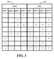
- FIG. 3 is a chart depicting combinations of transitional and non-transitional groups of the tallies that pass or fail in regard to detecting a predetermined baud rate. Combinations that pass, meaning that the predetermined baud rate is considered to have been detected, are listed in the rows of the pass column 302. Combinations that fail, meaning that the predetermined baud rate is considered not to have been detected, are listed in the rows of the fail column 304. In either column 302, 304 the letter "T" indicates a transitional group, while an empty space indicates a non-transitional group.
- baud detection passes if one, and only one, of the groups 204, 206, 208, 210 is defined to be transitional.
- Baud detection also passes if two, but no more than two, of the groups 204, 206, 208, 210 are defined to be transitional and the two groups share in common an identical subgroup 212-226.
- the first and second groups 204, 206 share in common the sub-groups 214, 216 consisting of the identical tallies 5-8.
- baud detection passes, as shown in the last row of the pass column 302.
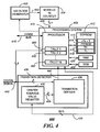
- FIG. 4 is an electrical block diagram of a baud detector 400 in accordance with the preferred embodiment of the present invention.
- the baud detector 400 comprises a conventional clock generator 402 for generating a clock signal 403 that is 16 times the predetermined baud rate that is to be detected.
- the clock generator 402 is coupled to a conventional modulo-16 counter 404 for counting the clock signal 403.
- the modulo-16 counter 404 is coupled by a counter output bus 406 to a processing system 408 for generating and storing the 16 tallies 202 in registers of a processor 410.
- the processor 410 communicates, among other things, via a communication bus 415, a detection of the predetermined baud rate in a digital signal 442.
- the processor 410 is similar to a model MC68HC05 microcomputer manufactured by Motorola, Inc. of Schaumburg, IL. It will be appreciated that other similar processors can be utilized as well for the processor 410.
- the processing system 408 also comprises a conventional electrically erasable programmable read-only memory (EEPROM) 412.
- the EEPROM 412 includes a location for pre-programming the predetermined percentage value 413 beyond which one of the groups 204, 206, 208, 210 is defined to be transitional, as described above.
- the EEPROM 412 also includes a location for pre-programming the length of the predetermined sampling period 414.
- the EEPROM 412 includes locations for pre-programming the high limit TH 416 and the low limit TL 418 for the expected range in the number of transitions during the sampling period.
- the processing system 408 further comprises a conventional random access memory (RAM) 420 for storing temporary variables and parameters, and a conventional read-only memory (ROM) 422 for permanently storing operating firmware.
- RAM random access memory
- ROM read-only memory
- EEPROM 412, the RAM 420, and the ROM 422 can be manufactured in whole or in part as an integral portion of the processor 410.
- the baud rate detector 400 further comprises a transition detector 430 coupled to the digital signal 442 for sampling the digital signal during the predetermined sampling period to detect transitions in the digital signal corresponding to the transitions 112 in the demodulated signal 102.
- the transition detector 430 comprises a register 432 coupled to the processing system 408 for storing a center average value (CAV) of the digital signal 442 as computed by the processing system 408.
- the digital signal 442 is also coupled to the processing system 408.
- the CAV is determined by the processing system 408 in a manner well known in the art by oversampling the digital signal 442 during a predetermined CAV sampling period and then calculating the average value of the samples collected.
- the transition detector 430 further comprises a transition definer 434 coupled to the digital signal 442 and coupled to the register 432 for defining a transition to have occurred when the digital signal 442 has passed through the CAV.
- the transition definer accomplishes detection of each transition by continuously comparing the value of the digital signal with the CAV.
- the transition definer 434 is coupled to the processing system 408 through an output 440 for generating an interrupt to the processing system 408 coincident with each transition detected in the digital signal.
- the transition definer 434 is similar to the model SN74LS682 eight-bit magnitude comparator manufactured by Motorola, Inc. of Schaumburg, IL. It will be appreciated that other similar comparators can be utilized as well for the transition definer 434.
- FIG. 5 is a flow chart depicting operation of the baud detector 400 in accordance with the preferred embodiment of the present invention.
- the flow begins with the processing system 408 awaiting 501 a request for baud detection via the communication bus 415, the request from an external device such as another processing system served by the baud detector 400.
- the processing system 408 controls the clock generator 402 to begin operating 502 at 16 times the predetermined baud that is to be detected.
- the processing system 408 then oversamples the digital signal 442 at, for example, four times the symbol rate of the digital signal 442 during a CAV determining period, e.g., 40 msec.
- the samples are averaged by the processing system 408 in a well-known manner to determine 504 the CAV of the digital signal 442 (corresponding, by way of example, to the center average value 107 of the demodulated signal 102).
- the processing system 408 then transfers the CAV to the register 432 via the bus 438 for comparison with the digital signal 442 by the transition definer 434 during the predetermined sampling period 414 to detect transitions of the digital signal 442.
- the processing system 408 then accesses the EEPROM 412 and controls the transition detector 430 to sample the digital signal 442 for the predetermined sampling period 414 pre-programmed into the EEPROM 412. Whenever the transition definer 434 detects a transition, the transition definer 434 sends an interrupt to the processing system 408 via the output 440. In response to the interrupt, the processing system 408 reads the current counter state indicated by the modulo-16 counter 404 on the counter output bus 406. The current counter state indicates to the processing system 408 which one of sixteen tally registers is to be incremented by a count of one for updating the corresponding one of the sixteen tallies 202 stored in the register. The processing system 408 then increments the tally 202 corresponding to the current counter state.
- This process is repeated for each transition of the digital signal 442 during the predetermined sampling period.
- the processing system 408 has generated 506 the sixteen tallies 202 that record how many of the transitions occurred coincident with each of the sixteen states of the counter 404 during the predetermined sampling period 414.
- the processing system 408 next sums the sixteen tallies 202 to compute 508 the total number of transitions detected over the predetermined sampling period 414.
- the processing system 408 preferably compares the total number of transitions with the low limit TL 418 and the high limit TH 416 to determine 509 whether the total number is within the expected range for the protocol utilized. If not, the processing system 408 informs 511 the external device that the baud rate was not detected. Flow then returns to step 510 to await another request for baud detection. It will be appreciated that, alternatively, step 509 can be omitted, and step 508 can proceed directly to step 510 without the range check.
- the processing system 408 forms 510 the four groups 204, 206, 208, 210 of the tallies 202 corresponding to contiguous sequential states of the counter 404, each group 204, 206, 208, 210 including the two sub-groups 212-226, each sub-group including four of the tallies 202, as described herein above.
- the processing system 408 then calculates 512 for each group 204, 206, 208, 210 a corresponding group number indicating how many of the transitions are recorded in the tallies belonging to the group.
- the processing system 408 For each group, the processing system 408 then compares the corresponding group number with the total number of transitions to determine what percentage of the total number of transitions belong to the group. If the percentage for the group exceeds the predetermined percentage value 413, then the processing system 408 defines 514 the group to be transitional.
- the processing system 408 next determines 516 whether the predetermined baud rate is present by deciding that the rate is present only if (a) exactly one of the groups 204, 206, 208, 210 is defined to be transitional, or (b) exactly two groups 204, 206, 208, 210 are defined to be transitional and the two groups 204, 206, 208, 210 share in common an identical sub-group 212-226. Flow then returns to step 511 to inform the external device as to whether or not the predetermined baud rate has been determined to be present in the digital signal 442. Flow then returns to step 501 to await another request for baud detection.
- the baud detector 400 in accordance with the preferred embodiment of the present invention provides several advantages over the prior art.
- the baud detector 400 is relatively fast, because it does not have to wait for a preamble portion of the signal, but can perform baud detection in any portion of the signal.
- the baud detector 400 can function over a wide range in the number of transitions occurring during the sampling period, making the baud detector 400 insensitive to the data being transmitted during baud detection.
- the baud detector 400 can be utilized with both two-level and multi-level modulation techniques, or a mix of both, thereby providing a high degree of flexibility.
- FIG. 6 is an electrical block diagram of a communication receiver 600 in accordance with the preferred embodiment of the present invention.
- the communication receiver 600 comprises a receiver antenna 602 for intercepting a communication signal from a radio transmitter (not shown).
- the receiver antenna 602 is coupled to a receiver element 604, which utilizes conventional demodulation techniques for receiving the communication signal from the transmitter.
- Radio signals received by the receiver element 604 produce the demodulated signal 102, which is coupled to an analog to digital A/D converter 642 to produce the digital signal 442.
- the digital signal 442 is coupled to a processing system 630 for processing messages received from the transmitter and is coupled to the baud detector 400 for detecting the presence of the predetermined baud rate in the digital signal 442.
- the baud detector 400 is coupled to the processing system 630 by the communication bus 415 for communicating, among other things, the presence or absence of the predetermined baud rate.
- a conventional power switch 606, coupled to the processing system 630 and coupled to a battery 616 is used to control the supply of power to the receiver element 604, thereby providing a battery saving function.
- the processing system 630 comprises a processor 608 coupled to a random access memory (RAM) 612, a read-only memory (ROM) 610, and an electrically erasable programmable read-only memory (EEPROM) 614.
- the processor 608 is similar to the M68HC08 micro-controller manufactured by Motorola, Inc. It will be appreciated that other similar processors can be utilized for the processor 608, and that additional processors of the same or alternative type, as well as a hardware decoder, can be added as required to handle the processing requirements of the processing system 630. It will be also appreciated that other types of memory, e.g., EEPROM or FLASH, can be utilized for the ROM 610, as well as the RAM 612.
- RAM 612 and the ROM 610 can be incorporated as an integral portion of the processor 608. It will be still further appreciated that, alternatively, the processing system 630 of the communication receiver 600 and the processing system 408 of the baud detector 400 can be combined into a single processing system.
- the processing system 630 is programmed by way of the ROM 610 to process incoming messages. To process a message, the processor 608 periodically activates the receiver element 604 through the power switch 606 and cooperates with the baud detector 400 to determine whether to remain on a currently selected channel (if the correct baud rate is detected within a predetermined time), or, conversely, to scan for another channel.
- the processor 608 decodes in a conventional manner an address in the demodulated data of the message, compares the decoded address with one or more selective call addresses 632 stored in the EEPROM 614, and when a match is detected, the processor 608 proceeds to decode a corresponding vector 620 received from the transmitter for designating where and when the transmitter will transmit an information portion of the message to the receiver 600.
- the vector 620 is stored in the RAM 612, and at the designated time the processing system 630 activates the receiver element 604 for receiving the information portion.
- the processor 608 Once the processor 608 has processed the message, it stores the message in a location for messages 618 in the RAM 612, and a call alerting signal is generated to alert a user that a message has been received.
- the call alerting signal is directed to a conventional audible or tactile alerting device 626 for generating an audible or tactile call alerting signal.
- the message can be accessed by the user through user controls 624, which provide functions such as lock, unlock, delete, read, etc. More specifically, by the use of appropriate functions provided by the user controls 624, the message is recovered from the RAM 612, and then conveyed to the user through a user interface 628, e.g., a conventional liquid crystal display (LCD), or a loudspeaker.
- LCD liquid crystal display
- the present invention provides a baud rate detector that is fast and can accurately detect a predetermined baud rate during both the preamble and information portions of a communication signal.
- the baud rate detector advantageously can function over a broad range in the number of transitions occurring during a sampling period utilized for detecting the predetermined baud rate.
- the baud rate detector is also capable of operating correctly in a mix of two-level and multi-level modulation schemes.
Landscapes
- Engineering & Computer Science (AREA)
- Power Engineering (AREA)
- Computer Networks & Wireless Communication (AREA)
- Signal Processing (AREA)
- Communication Control (AREA)
- Dc Digital Transmission (AREA)
Abstract
Description
- This invention relates in general to digital communication systems, and more specifically to a method and apparatus for detecting a presence of a predetermined baud rate in a digital signal.
- Baud rate detectors have been used by receivers in radio communication systems for detecting a specific baud rate associated with a communication protocol compatible with the receivers. Such detectors can quickly determine whether a desired communication protocol is present on a communication channel, or that the channel is inactive.
- Prior art receivers used in messaging systems typically have operated on a single radio frequency and have operated with protocols that have included preamble portions having a two-level one-zero pattern. Such receivers have employed relatively simple baud rate detectors for detecting the baud rate during one of the preamble portions.
- Modern messaging protocols, such as the European Radio Messaging System (ERMES) protocol, require scanning receivers capable of operating on multiple radio frequencies. To minimize scanning time, the baud rate detectors operating on such protocols must be fast, implying that the detectors must operate during information portions of the signal as well as during the preamble portions. Unlike the preamble portions, which provide a constant number of transitions in a given sampling period, the information portions of the signal can have a wide ranging number of transitions in a given sampling period. In addition, the information portions typically utilize multi-level modulation, such as four-level frequency-shift-key (FSK) modulation.
- Thus what is needed is a baud rate detector that is fast and can accurately detect a predetermined baud rate during both the preamble and information portions of the signal. The baud rate detector preferably should function over a broad range in the number of transitions occurring during a sampling period utilized for detecting the predetermined baud rate. The baud rate detector also preferably should be capable of operating correctly in a mix of two-level and multi-level modulation schemes.
- An aspect of the present invention is a baud detector for detecting a presence of a predetermined baud rate in a digital signal. The baud detector comprises a clock generator for generating a clock signal operating at a clock rate that is N times the predetermined baud rate, wherein N is a positive integer, and a modulo counter coupled to the clock generator for counting the clock signal, the modulo counter utilizing N states, and a transition detector coupled to the digital signal for sampling the digital signal during a predetermined sampling period to detect transitions of the digital signal. The baud detector further comprises a processing system coupled to the transition detector and coupled to the modulo counter for generating N tallies that record how many of the transitions occur coincident with each of the states of the modulo counter over the predetermined sampling period. The processing system is programmed for computing a total number of transitions detected over the predetermined sampling period, and forming M groups of the tallies corresponding to contiguous sequential states of the modulo counter, wherein M is a positive integer. The processing system is further programmed for calculating for each group a corresponding group number indicating how many of the transitions are recorded in the tallies of the group, and, for each group, defining the group to be transitional in response to the corresponding group number exceeding a predetermined percentage of the total number of transitions. The processing system is also programmed for determining whether the predetermined baud rate is present in response to the groups that are defined to be transitional.
- Another aspect of the present invention is a communication receiver for detecting a presence of a predetermined baud rate in a communication signal comprising a digital signal carrying information. The communication receiver comprises an antenna for intercepting the communication signal, and a receiver element coupled to the antenna for demodulating the communication signal to derive the digital signal. The communication receiver further comprises a first processing system coupled to the receiver element for processing the digital signal and controlling the communication receiver, and user controls coupled to the first processing system for providing control of the communication receiver by a user. The communication receiver also includes a user interface coupled to the first processing system for conveying to the user the information carried in the digital signal, and a baud detector coupled to the first processing system for detecting the predetermined baud rate. The baud detector comprises a clock generator for generating a clock signal operating at a clock rate that is N times the predetermined baud rate, wherein N is a positive integer, and a modulo counter coupled to the clock generator for counting the clock signal, the modulo counter utilizing N states. The baud detector further comprises a transition detector coupled to the digital signal for sampling the digital signal during a predetermined sampling period to detect transitions of the digital signal, and a second processing system coupled to the transition detector and coupled to the modulo counter for generating N tallies that record how many of the transitions occur coincident with each of the states of the modulo counter over the predetermined sampling period. The second processing system is programmed for computing a total number of transitions detected over the predetermined sampling period, and forming M groups of the tallies corresponding to contiguous sequential states of the modulo counter, wherein M is a positive integer. The second processing system is further programmed for calculating for each group a corresponding group number indicating how many of the transitions are recorded in the tallies of the group, and, for each group, defining the group to be transitional in response to the corresponding group number exceeding a predetermined percentage of the total number of transitions. The second processing system is also programmed for determining whether the predetermined baud rate is present in response to the groups that are defined to be transitional.
- FIG. 1 is a timing diagram of a four-level FSK demodulated signal.
- FIG. 2 is a diagram depicting a grouping of tallies of transitions of a digital signal in accordance with the preferred embodiment of the present invention.
- FIG. 3 is a chart depicting combinations of transitional and non-transitional groups of the tallies that pass or fail in regard to detecting a predetermined baud rate.
- FIG. 4 is an electrical block diagram of a baud detector in accordance with the preferred embodiment of the present invention.
- FIG. 5 is a flow chart depicting operation of the baud detector in accordance with the preferred embodiment of the present invention.
- FIG. 6 is an electrical block diagram of a communication receiver in accordance with the preferred embodiment of the present invention.
- Referring to FIG. 1, a timing diagram depicts a four-level FSK demodulated
signal 102 having symbols represented by fourvoltage levels average value 107 is also depicted.Transitions 112 of the demodulatedsignal 102 are indicated where the demodulatedsignal 102 passes through the centeraverage value 107. While the four-level demodulatedsignal 102 is used by way of example, it will become apparent to one of ordinary skill in the art that the claimed invention will perform baud detection on M-ary signals having any number of modulation levels. - Referring to FIG. 2, a diagram depicts a grouping of 16
tallies 202 of transitions of a digital signal corresponding to the demodulatedsignal 102 in accordance with the preferred embodiment of the present invention. To obtain the 16 tallies 202 a modulo-16 counter is clocked at a clock rate of 16 times a predetermined baud rate to be detected. The demodulatedsignal 102 is converted to a digital signal, which is then sampled for a predetermined sampling period, e.g., 40 msec. The 16tallies 202 correspond to the 16 states of the modulo-16 counter and record how many transitions occur during the predetermined sampling period while the counter is in each of the 16 states. The 16tallies 202 are summed at the end of the predetermined sampling period to compute the total number of transitions that have occurred during the predetermined sampling period. Preferably, detection of the predetermined baud rate is determined to have failed if the total number of transitions is outside of a predetermined range specified by a low limit TL and a high limit TH, TL and TH being positive integers, e.g., 10 and 256, respectively, in the case of the European Radio Messaging System (ERMES) protocol. - If the total number is within the predetermined range, the
tallies 202 are then grouped into fourgroups first group 204 comprises twosub-groups tallies 1 through 4 andtallies 5 through 8. Thesecond group 206 comprises twosub-groups tallies 5 through 8 andtallies 9 through 12. Thethird group 208 comprises twosub-groups tallies 9 through 12 andtallies 13 through 16. Thefourth group 210 comprises twosub-groups tallies 1 through 4 andtallies 13 through 16. - The
tallies 202 belonging to each of thegroups groups tallies 202 of each group. The group numbers are then compared with the total number of transitions that have occurred during the predetermined sampling period to determine what percentage of the total number of transitions are recorded in thetallies 202 belonging to eachgroup groups - While the preceding discussion has, by way of example, presented a preferred configuration of groups and tallies, it will be appreciated that, alternatively, other sizes, numbers, and combinations of groups and tallies can be selected in accordance with the present invention. For example, a larger number of groups, e.g., 8 groups, having 6 or 8 tallies each, can be utilized to improve resolution. In addition, the number of tallies can be changed, e.g., to 32 or 8. These and other similar variations can be expected to occur to one of ordinary skill in the art who has been taught from the disclosure presented herein of the preferred embodiment of the present invention.
- FIG. 3 is a chart depicting combinations of transitional and non-transitional groups of the tallies that pass or fail in regard to detecting a predetermined baud rate. Combinations that pass, meaning that the predetermined baud rate is considered to have been detected, are listed in the rows of the
pass column 302. Combinations that fail, meaning that the predetermined baud rate is considered not to have been detected, are listed in the rows of thefail column 304. In eithercolumn - Note that baud detection passes if one, and only one, of the
groups groups second groups sub-groups groups pass column 302. - FIG. 4 is an electrical block diagram of a
baud detector 400 in accordance with the preferred embodiment of the present invention. Thebaud detector 400 comprises aconventional clock generator 402 for generating aclock signal 403 that is 16 times the predetermined baud rate that is to be detected. Theclock generator 402 is coupled to a conventional modulo-16counter 404 for counting theclock signal 403. The modulo-16counter 404 is coupled by acounter output bus 406 to aprocessing system 408 for generating and storing the 16tallies 202 in registers of aprocessor 410. Theprocessor 410 communicates, among other things, via acommunication bus 415, a detection of the predetermined baud rate in adigital signal 442. Preferably, theprocessor 410 is similar to a model MC68HC05 microcomputer manufactured by Motorola, Inc. of Schaumburg, IL. It will be appreciated that other similar processors can be utilized as well for theprocessor 410. - The
processing system 408 also comprises a conventional electrically erasable programmable read-only memory (EEPROM) 412. TheEEPROM 412 includes a location for pre-programming thepredetermined percentage value 413 beyond which one of thegroups EEPROM 412 also includes a location for pre-programming the length of the predetermined sampling period 414. In addition, theEEPROM 412 includes locations for pre-programming thehigh limit TH 416 and thelow limit TL 418 for the expected range in the number of transitions during the sampling period. - The
processing system 408 further comprises a conventional random access memory (RAM) 420 for storing temporary variables and parameters, and a conventional read-only memory (ROM) 422 for permanently storing operating firmware. It will be appreciated that, alternatively, theEEPROM 412, theRAM 420, and theROM 422 can be manufactured in whole or in part as an integral portion of theprocessor 410. - The
baud rate detector 400 further comprises atransition detector 430 coupled to thedigital signal 442 for sampling the digital signal during the predetermined sampling period to detect transitions in the digital signal corresponding to thetransitions 112 in thedemodulated signal 102. Thetransition detector 430 comprises aregister 432 coupled to theprocessing system 408 for storing a center average value (CAV) of thedigital signal 442 as computed by theprocessing system 408. Thedigital signal 442 is also coupled to theprocessing system 408. The CAV is determined by theprocessing system 408 in a manner well known in the art by oversampling thedigital signal 442 during a predetermined CAV sampling period and then calculating the average value of the samples collected. - The
transition detector 430 further comprises atransition definer 434 coupled to thedigital signal 442 and coupled to theregister 432 for defining a transition to have occurred when thedigital signal 442 has passed through the CAV. The transition definer accomplishes detection of each transition by continuously comparing the value of the digital signal with the CAV. Thetransition definer 434 is coupled to theprocessing system 408 through anoutput 440 for generating an interrupt to theprocessing system 408 coincident with each transition detected in the digital signal. Preferably thetransition definer 434 is similar to the model SN74LS682 eight-bit magnitude comparator manufactured by Motorola, Inc. of Schaumburg, IL. It will be appreciated that other similar comparators can be utilized as well for thetransition definer 434. - FIG. 5 is a flow chart depicting operation of the
baud detector 400 in accordance with the preferred embodiment of the present invention. The flow begins with theprocessing system 408 awaiting 501 a request for baud detection via thecommunication bus 415, the request from an external device such as another processing system served by thebaud detector 400. When the request arrives, theprocessing system 408 controls theclock generator 402 to begin operating 502 at 16 times the predetermined baud that is to be detected. Theprocessing system 408 then oversamples thedigital signal 442 at, for example, four times the symbol rate of thedigital signal 442 during a CAV determining period, e.g., 40 msec. The samples are averaged by theprocessing system 408 in a well-known manner to determine 504 the CAV of the digital signal 442 (corresponding, by way of example, to the centeraverage value 107 of the demodulated signal 102). Theprocessing system 408 then transfers the CAV to theregister 432 via thebus 438 for comparison with thedigital signal 442 by thetransition definer 434 during the predetermined sampling period 414 to detect transitions of thedigital signal 442. - The
processing system 408 then accesses theEEPROM 412 and controls thetransition detector 430 to sample thedigital signal 442 for the predetermined sampling period 414 pre-programmed into theEEPROM 412. Whenever thetransition definer 434 detects a transition, thetransition definer 434 sends an interrupt to theprocessing system 408 via theoutput 440. In response to the interrupt, theprocessing system 408 reads the current counter state indicated by the modulo-16counter 404 on thecounter output bus 406. The current counter state indicates to theprocessing system 408 which one of sixteen tally registers is to be incremented by a count of one for updating the corresponding one of the sixteentallies 202 stored in the register. Theprocessing system 408 then increments thetally 202 corresponding to the current counter state. This process is repeated for each transition of thedigital signal 442 during the predetermined sampling period. At the end of the predetermined sampling period 414, theprocessing system 408 has generated 506 the sixteentallies 202 that record how many of the transitions occurred coincident with each of the sixteen states of thecounter 404 during the predetermined sampling period 414. - The
processing system 408 next sums the sixteentallies 202 to compute 508 the total number of transitions detected over the predetermined sampling period 414. Next theprocessing system 408 preferably compares the total number of transitions with thelow limit TL 418 and thehigh limit TH 416 to determine 509 whether the total number is within the expected range for the protocol utilized. If not, theprocessing system 408 informs 511 the external device that the baud rate was not detected. Flow then returns to step 510 to await another request for baud detection. It will be appreciated that, alternatively, step 509 can be omitted, and step 508 can proceed directly to step 510 without the range check. - If, on the other hand, the total number of transitions is within the expected range, then the
processing system 408forms 510 the fourgroups tallies 202 corresponding to contiguous sequential states of thecounter 404, eachgroup tallies 202, as described herein above. Theprocessing system 408 then calculates 512 for eachgroup processing system 408 then compares the corresponding group number with the total number of transitions to determine what percentage of the total number of transitions belong to the group. If the percentage for the group exceeds thepredetermined percentage value 413, then theprocessing system 408 defines 514 the group to be transitional. - The
processing system 408 next determines 516 whether the predetermined baud rate is present by deciding that the rate is present only if (a) exactly one of thegroups groups groups digital signal 442. Flow then returns to step 501 to await another request for baud detection. - The
baud detector 400 in accordance with the preferred embodiment of the present invention provides several advantages over the prior art. First, thebaud detector 400 is relatively fast, because it does not have to wait for a preamble portion of the signal, but can perform baud detection in any portion of the signal. Second, thebaud detector 400 can function over a wide range in the number of transitions occurring during the sampling period, making thebaud detector 400 insensitive to the data being transmitted during baud detection. Third, thebaud detector 400 can be utilized with both two-level and multi-level modulation techniques, or a mix of both, thereby providing a high degree of flexibility. - FIG. 6 is an electrical block diagram of a
communication receiver 600 in accordance with the preferred embodiment of the present invention. Thecommunication receiver 600 comprises areceiver antenna 602 for intercepting a communication signal from a radio transmitter (not shown). Thereceiver antenna 602 is coupled to areceiver element 604, which utilizes conventional demodulation techniques for receiving the communication signal from the transmitter. Radio signals received by thereceiver element 604 produce thedemodulated signal 102, which is coupled to an analog to digital A/D converter 642 to produce thedigital signal 442. Thedigital signal 442 is coupled to aprocessing system 630 for processing messages received from the transmitter and is coupled to thebaud detector 400 for detecting the presence of the predetermined baud rate in thedigital signal 442. Thebaud detector 400 is coupled to theprocessing system 630 by thecommunication bus 415 for communicating, among other things, the presence or absence of the predetermined baud rate. Aconventional power switch 606, coupled to theprocessing system 630 and coupled to abattery 616 is used to control the supply of power to thereceiver element 604, thereby providing a battery saving function. - To perform the necessary functions of the
communication receiver 600, theprocessing system 630 comprises aprocessor 608 coupled to a random access memory (RAM) 612, a read-only memory (ROM) 610, and an electrically erasable programmable read-only memory (EEPROM) 614. Preferably, theprocessor 608 is similar to the M68HC08 micro-controller manufactured by Motorola, Inc. It will be appreciated that other similar processors can be utilized for theprocessor 608, and that additional processors of the same or alternative type, as well as a hardware decoder, can be added as required to handle the processing requirements of theprocessing system 630. It will be also appreciated that other types of memory, e.g., EEPROM or FLASH, can be utilized for theROM 610, as well as theRAM 612. It will be further appreciated that theRAM 612 and theROM 610, singly or in combination, can be incorporated as an integral portion of theprocessor 608. It will be still further appreciated that, alternatively, theprocessing system 630 of thecommunication receiver 600 and theprocessing system 408 of thebaud detector 400 can be combined into a single processing system. - The
processing system 630 is programmed by way of theROM 610 to process incoming messages. To process a message, theprocessor 608 periodically activates thereceiver element 604 through thepower switch 606 and cooperates with thebaud detector 400 to determine whether to remain on a currently selected channel (if the correct baud rate is detected within a predetermined time), or, conversely, to scan for another channel. During message processing following successful baud rate detection, theprocessor 608 decodes in a conventional manner an address in the demodulated data of the message, compares the decoded address with one or more selective call addresses 632 stored in theEEPROM 614, and when a match is detected, theprocessor 608 proceeds to decode acorresponding vector 620 received from the transmitter for designating where and when the transmitter will transmit an information portion of the message to thereceiver 600. Thevector 620 is stored in theRAM 612, and at the designated time theprocessing system 630 activates thereceiver element 604 for receiving the information portion. - Once the
processor 608 has processed the message, it stores the message in a location formessages 618 in theRAM 612, and a call alerting signal is generated to alert a user that a message has been received. The call alerting signal is directed to a conventional audible ortactile alerting device 626 for generating an audible or tactile call alerting signal. The message can be accessed by the user throughuser controls 624, which provide functions such as lock, unlock, delete, read, etc. More specifically, by the use of appropriate functions provided by the user controls 624, the message is recovered from theRAM 612, and then conveyed to the user through auser interface 628, e.g., a conventional liquid crystal display (LCD), or a loudspeaker. - Thus, it should be apparent by now that the present invention provides a baud rate detector that is fast and can accurately detect a predetermined baud rate during both the preamble and information portions of a communication signal. The baud rate detector advantageously can function over a broad range in the number of transitions occurring during a sampling period utilized for detecting the predetermined baud rate. The baud rate detector is also capable of operating correctly in a mix of two-level and multi-level modulation schemes.
- While the foregoing description has presented a preferred embodiment in accordance with the present invention, it will be appreciated by one of ordinary skill in the art that various changes and modifications can be made, as discussed herein above. Accordingly, the scope of the invention is delimited only in accordance with the following claims.
Claims (12)
- A baud detector for detecting a presence of a predetermined baud rate in a digital signal, the baud detector comprising:a clock generator for generating a clock signal operating at a clock rate that is N times the predetermined baud rate, wherein N is a positive integer;a modulo counter coupled to the clock generator for counting the clock signal, the modulo counter utilizing N states;a transition detector coupled to the digital signal for sampling the digital signal during a predetermined sampling period to detect transitions of the digital signal; anda processing system coupled to the transition detector and coupled to the modulo counter for generating N tallies that record how many of the transitions occur coincident with each of the states of the modulo counter over the predetermined sampling period, wherein the processing system is programmed for:computing a total number of transitions detected over the predetermined sampling period;forming M groups of the tallies corresponding to contiguous sequential states of the modulo counter, wherein M is a positive integer;calculating for each group a corresponding group number indicating how many of the transitions are recorded in the tallies of the group;for each group, defining the group to be transitional in response to the corresponding group number exceeding a predetermined percentage of the total number of transitions; anddetermining whether the predetermined baud rate is present in response to the groups that are defined to be transitional.
- The baud detector of claim 1,
wherein N is a multiple of four, and
wherein the processing system is further programmed for:forming four groups of the tallies, each group comprising two sub-groups, each sub-group including one-quarter of the tallies, anddeciding that the predetermined baud rate is present only if:one, but no more than one, of the four groups is defined to be transitional, ortwo, but no more than two, of the four groups are defined to be transitional, and the two share an identical sub-group in common. - The baud detector of claim 1,
wherein the processing system is further programmed for determining a center average value for the digital signal, and
wherein the transition detector comprises:a register coupled to the processing system for storing the center average value; anda transition definer coupled to the register and coupled to the digital signal for defining a transition to have occurred when the digital signal has passed through the center average value. - The baud detector of claim 1,
wherein the predetermined sampling period is programmable, and
wherein the processing system is further programmed for determining the predetermined sampling period by accessing a programmable memory location. - The baud detector of claim 1, wherein the processing system is further programmed for deciding that the predetermined baud rate is present only if the total number of transitions detected over the predetermined sampling period is between TL and TH, inclusive, wherein TL and TH are positive integers.
- The baud detector of claim 5,
wherein the digital signal conforms to a protocol defined by a European Radio Messaging System (ERMES) specification, and
wherein TL = 4 and TH = 256. - A communication receiver for detecting a presence of a predetermined baud rate in a communication signal comprising a digital signal carrying information, the communication receiver comprising:an antenna for intercepting the communication signal;a receiver element coupled to the antenna for demodulating the communication signal to derive the digital signal;a first processing system coupled to the receiver element for processing the digital signal and controlling the communication receiver;user controls coupled to the first processing system for providing control of the communication receiver by a user;a user interface coupled to the first processing system for conveying to the user the information carried in the digital signal; anda baud detector coupled to the first processing system for detecting the predetermined baud rate, the baud detector comprising:a clock generator for generating a clock signal operating at a clock rate that is N times the predetermined baud rate, wherein N is a positive integer;a modulo counter coupled to the clock generator for counting the clock signal, the modulo counter utilizing N states;a transition detector coupled to the digital signal for sampling the digital signal during a predetermined sampling period to detect transitions of the digital signal; anda second processing system coupled to the transition detector and coupled to the modulo counter for generating N tallies that record how many of the transitions occur coincident with each of the states of the modulo counter over the predetermined sampling period, wherein the second processing system is programmed for:computing a total number of transitions detected over the predetermined sampling period;forming M groups of the tallies corresponding to contiguous sequential states of the modulo counter, wherein M is a positive integer;calculating for each group a corresponding group number indicating how many of the transitions are recorded in the tallies of the group;for each group, defining the group to be transitional in response to the corresponding group number exceeding a predetermined percentage of the total number of transitions; anddetermining whether the predetermined baud rate is present in response to the groups that are defined to be transitional.
- The communication receiver of claim 7,
wherein N is a multiple of four, and
wherein the second processing system is further programmed for:forming four groups of the tallies, each group comprising two sub-groups, each sub-group including one-quarter of the tallies, anddeciding that the predetermined baud rate is present only if:one, but no more than one, of the four groups is defined to be transitional, ortwo, but no more than two, of the four groups are defined to be transitional, and the two share an identical sub-group in common. - The communication receiver of claim 7,
wherein the second processing system is further programmed for determining a center average value for the digital signal, and
wherein the transition detector comprises:a register coupled to the second processing system for storing the center average value; anda transition definer coupled to the register and coupled to the digital signal for defining a transition to have occurred when the digital signal has passed through the center average value. - The communication receiver of claim 7,
wherein the predetermined sampling period is programmable, and
wherein the second processing system is further programmed for determining the predetermined sampling period by accessing a programmable memory location. - The communication receiver of claim 7, wherein the second processing system is further programmed for deciding that the predetermined baud rate is present only if the total number of transitions detected over the predetermined sampling period is between TL and TH, inclusive, wherein TL and TH are positive integers.
- The communication receiver of claim 11,
wherein the digital signal conforms to a protocol defined by a European Radio Messaging System (ERMES) specification, and
wherein TL = 4 and TH = 256.
Applications Claiming Priority (2)
| Application Number | Priority Date | Filing Date | Title |
|---|---|---|---|
| US08/569,893 US5724389A (en) | 1995-12-08 | 1995-12-08 | Method and apparatus for detecting a presence of a predetermined baud rate |
| US569893 | 1995-12-08 |
Publications (2)
| Publication Number | Publication Date |
|---|---|
| EP0777366A2 true EP0777366A2 (en) | 1997-06-04 |
| EP0777366A3 EP0777366A3 (en) | 1999-12-29 |
Family
ID=24277329
Family Applications (1)
| Application Number | Title | Priority Date | Filing Date |
|---|---|---|---|
| EP96119529A Withdrawn EP0777366A3 (en) | 1995-12-08 | 1996-12-05 | Apparatus for detecting a presence of a predetermined baud rate |
Country Status (2)
| Country | Link |
|---|---|
| US (1) | US5724389A (en) |
| EP (1) | EP0777366A3 (en) |
Cited By (2)
| Publication number | Priority date | Publication date | Assignee | Title |
|---|---|---|---|---|
| WO1997041664A2 (en) * | 1996-04-30 | 1997-11-06 | Philips Electronics N.V. | Synchronization of multistandard television apparatus |
| WO2001093518A1 (en) * | 2000-05-31 | 2001-12-06 | Koninklijke Philips Electronics N.V. | Method and receiver for estimating data bit rates |
Families Citing this family (9)
| Publication number | Priority date | Publication date | Assignee | Title |
|---|---|---|---|---|
| US5835530A (en) * | 1995-12-21 | 1998-11-10 | Corsair Communications, Inc. | Bit characteristics measurement system for digitally modulated signals |
| US6515577B1 (en) * | 1997-01-10 | 2003-02-04 | Motorola, Inc. | Channel monitoring by a multichannel selective call receiver |
| WO1998037665A1 (en) * | 1997-02-02 | 1998-08-27 | Fonefriend Systems, Inc. | Internet switch box, system and method for internet telephony |
| WO1998036545A1 (en) * | 1997-02-14 | 1998-08-20 | Motorola Inc. | Method and apparatus for processing a multi-level fsk signal |
| US5982837A (en) * | 1997-06-16 | 1999-11-09 | Lsi Logic Corporation | Automatic baud rate detector |
| US6366610B1 (en) * | 1998-05-15 | 2002-04-02 | Advanced Micro Devices, Inc. | Autobauding with adjustment to a programmable baud rate |
| US6111855A (en) * | 1998-08-03 | 2000-08-29 | Motorola | Method and apparatus for baud detection in a communication device |
| WO2006138344A1 (en) * | 2005-06-14 | 2006-12-28 | Siemens Vdo Automotive Corporation | Signal recognition for combined receiver for remote keyless entry and pressure monitoring systems |
| CN106034092B (en) * | 2015-03-17 | 2019-11-26 | 杭州讯能科技有限公司 | A kind of method, equipment and the system of serial port baud rate automatic identification |
Family Cites Families (15)
| Publication number | Priority date | Publication date | Assignee | Title |
|---|---|---|---|---|
| US5095498A (en) * | 1989-02-06 | 1992-03-10 | Motorola, Inc. | Bit synchronizer |
| US5049875A (en) * | 1989-09-13 | 1991-09-17 | Motorola Inc. | Method and apparatus for out of range detection in response to nondetection of predetermined baud rates |
| US5181227A (en) * | 1990-01-02 | 1993-01-19 | Motorola, Inc. | Receiver having a signal detector and bit synchronizer |
| US5077758A (en) * | 1990-01-02 | 1991-12-31 | Motorola, Inc. | Signal detector and bit synchronizer |
| JP2800858B2 (en) * | 1991-09-18 | 1998-09-21 | 日本電気株式会社 | Wireless telephone equipment |
| US5311554A (en) * | 1992-07-02 | 1994-05-10 | Motorola, Inc. | Synchronized offset extraction in a data receiver |
| US5627858A (en) * | 1992-07-20 | 1997-05-06 | Telefonaktiebolaget L M Ericsson | Multi-channel autobauding circuit |
| US5376929A (en) * | 1992-11-27 | 1994-12-27 | Motorola, Inc. | Selective call receiver with battery saving features and method therefor |
| US5349695A (en) * | 1992-12-03 | 1994-09-20 | Motorola, Inc. | Selective call receiver having CMOS power-on reset circuit |
| JP3060837B2 (en) * | 1993-06-10 | 2000-07-10 | モトローラ・インコーポレイテッド | Battery saving method and device in wireless communication device |
| US5563910A (en) * | 1993-11-12 | 1996-10-08 | Motorola, Inc. | Recursive baud rate detection method and apparatus |
| US5497145A (en) * | 1994-07-05 | 1996-03-05 | Motorola, Inc. | Selective call receiver with battery saving features and method therefor |
| US5561693A (en) * | 1994-08-01 | 1996-10-01 | Motorola, Inc. | Selective call receiver with battery saving features and method therefor |
| US5490179A (en) * | 1994-09-06 | 1996-02-06 | Motorola, Inc. | Signal grading in a selective call receiver for automatic gain control |
| US5689806A (en) * | 1995-12-26 | 1997-11-18 | Motorola, Inc. | Communication receiver for selecting between scanning and locking to a channel and method therefor |
-
1995
- 1995-12-08 US US08/569,893 patent/US5724389A/en not_active Expired - Fee Related
-
1996
- 1996-12-05 EP EP96119529A patent/EP0777366A3/en not_active Withdrawn
Non-Patent Citations (1)
| Title |
|---|
| None |
Cited By (5)
| Publication number | Priority date | Publication date | Assignee | Title |
|---|---|---|---|---|
| WO1997041664A2 (en) * | 1996-04-30 | 1997-11-06 | Philips Electronics N.V. | Synchronization of multistandard television apparatus |
| WO1997041664A3 (en) * | 1996-04-30 | 1997-12-18 | Philips Electronics Nv | Synchronization of multistandard television apparatus |
| WO2001093518A1 (en) * | 2000-05-31 | 2001-12-06 | Koninklijke Philips Electronics N.V. | Method and receiver for estimating data bit rates |
| JP2003535505A (en) * | 2000-05-31 | 2003-11-25 | コーニンクレッカ フィリップス エレクトロニクス エヌ ヴィ | Data bit rate estimation method and receiver |
| US6898237B2 (en) | 2000-05-31 | 2005-05-24 | Koninklijke Philips Electronics N.V. | Method of, and receiver for, estimating the bit rate of data |
Also Published As
| Publication number | Publication date |
|---|---|
| US5724389A (en) | 1998-03-03 |
| EP0777366A3 (en) | 1999-12-29 |
Similar Documents
| Publication | Publication Date | Title |
|---|---|---|
| EP0108938B1 (en) | Digital paging system having bit rate switching means and digital paging receiver therefor | |
| US5724389A (en) | Method and apparatus for detecting a presence of a predetermined baud rate | |
| US5049875A (en) | Method and apparatus for out of range detection in response to nondetection of predetermined baud rates | |
| US5359607A (en) | Adaptive intermodulation control | |
| GB2144565A (en) | Decoding arrangements | |
| US5077758A (en) | Signal detector and bit synchronizer | |
| JPH07500714A (en) | Data communications terminal with variable length message carryover | |
| AU675578B2 (en) | Communication system for communicating with a plurality of selective call receivers and method therefor | |
| US5533062A (en) | Method and apparatus for carrier tracking and demodulation | |
| EP0639310A1 (en) | Selective call receiver with a universal synchronization code operating mode | |
| WO1994001951A1 (en) | Synchronized offset extraction in a data receiver | |
| US5694438A (en) | Method and apparatus for managing a data symbol received in a time diversity communication system | |
| EP0532552B1 (en) | Time based signal detector | |
| US5670951A (en) | Radio communication device and method for generating threshold levels in a radio communication device for receiving four-level signals | |
| US5627860A (en) | Peak and valley detector for a selective call receiving device | |
| US5686898A (en) | Paging network identification information distributed in address field | |
| JPH06326649A (en) | Selective radio call signal receiver | |
| US5233345A (en) | Selective calling receiver with multiple clock frequencies for receiving long messages | |
| US5181227A (en) | Receiver having a signal detector and bit synchronizer | |
| US5805980A (en) | Communication receiver for controlling a receive operation in response to a control value | |
| US5689806A (en) | Communication receiver for selecting between scanning and locking to a channel and method therefor | |
| WO1994014286A1 (en) | Selective call receiver with battery saving function in first and second modes and method therefor | |
| EP0465463A4 (en) | Power conservation method and apparatus for a portion of a predetermined signal | |
| CA2072591C (en) | Multiple frequency scanning in a selective call communication system | |
| US5206636A (en) | Signal search method for selective call receiver |
Legal Events
| Date | Code | Title | Description |
|---|---|---|---|
| PUAI | Public reference made under article 153(3) epc to a published international application that has entered the european phase |
Free format text: ORIGINAL CODE: 0009012 |
|
| AK | Designated contracting states |
Kind code of ref document: A2 Designated state(s): DE FR GB IT NL SE |
|
| PUAL | Search report despatched |
Free format text: ORIGINAL CODE: 0009013 |
|
| AK | Designated contracting states |
Kind code of ref document: A3 Designated state(s): DE FR GB IT NL SE |
|
| 17P | Request for examination filed |
Effective date: 20000629 |
|
| 17Q | First examination report despatched |
Effective date: 20010219 |
|
| STAA | Information on the status of an ep patent application or granted ep patent |
Free format text: STATUS: THE APPLICATION IS DEEMED TO BE WITHDRAWN |
|
| 18D | Application deemed to be withdrawn |
Effective date: 20010630 |
|
| P01 | Opt-out of the competence of the unified patent court (upc) registered |
Effective date: 20230525 |