EP0777342B1 - A terrestrial flight telephone system - Google Patents
A terrestrial flight telephone system Download PDFInfo
- Publication number
- EP0777342B1 EP0777342B1 EP96307423A EP96307423A EP0777342B1 EP 0777342 B1 EP0777342 B1 EP 0777342B1 EP 96307423 A EP96307423 A EP 96307423A EP 96307423 A EP96307423 A EP 96307423A EP 0777342 B1 EP0777342 B1 EP 0777342B1
- Authority
- EP
- European Patent Office
- Prior art keywords
- station
- air
- oscillator
- ground
- ground station
- Prior art date
- Legal status (The legal status is an assumption and is not a legal conclusion. Google has not performed a legal analysis and makes no representation as to the accuracy of the status listed.)
- Expired - Lifetime
Links
- 238000012937 correction Methods 0.000 claims description 49
- 230000005540 biological transmission Effects 0.000 claims description 38
- 238000012544 monitoring process Methods 0.000 claims description 27
- 230000001360 synchronised effect Effects 0.000 claims description 6
- 238000000034 method Methods 0.000 claims description 5
- 230000004044 response Effects 0.000 claims description 4
- 230000000979 retarding effect Effects 0.000 claims description 4
- 230000007423 decrease Effects 0.000 claims description 3
- 230000007774 longterm Effects 0.000 description 5
- 238000004891 communication Methods 0.000 description 4
- 239000013078 crystal Substances 0.000 description 3
- 230000001413 cellular effect Effects 0.000 description 1
- 238000010586 diagram Methods 0.000 description 1
- 238000009434 installation Methods 0.000 description 1
- 230000002045 lasting effect Effects 0.000 description 1
- 238000012986 modification Methods 0.000 description 1
- 230000004048 modification Effects 0.000 description 1
- 230000035945 sensitivity Effects 0.000 description 1
- 230000008054 signal transmission Effects 0.000 description 1
Images
Classifications
-
- H—ELECTRICITY
- H04—ELECTRIC COMMUNICATION TECHNIQUE
- H04B—TRANSMISSION
- H04B7/00—Radio transmission systems, i.e. using radiation field
- H04B7/14—Relay systems
- H04B7/15—Active relay systems
- H04B7/185—Space-based or airborne stations; Stations for satellite systems
- H04B7/18502—Airborne stations
- H04B7/18506—Communications with or from aircraft, i.e. aeronautical mobile service
Definitions
- the present invention relates to a terrestrial flight telecommunications system and a method of operating same, and more particularly it relates to synchronising an air station with a ground station.
- Terrestrial flight telephone systems are being developed for commercial airliners to enable passengers on those airliners to communicate with the public switched telephone network (PSTN).
- PSTN public switched telephone network
- These systems some of which are already in service on a trial basis, operate in a manner similar to a cellular mobile telephone system, in that each aircraft comprises what is termed an "air station" which communicates with a selected one of a plurality of ground stations, one way in which the selection process could be made being described in a co-pending European patent application 96305380.6 entitled "A Telecommunications System".
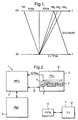
- FIG. 1 there is illustrated a schematic timing diagram which enables synchronisation to be achieved between a ground station and a number of air stations in a time division multiple access (TDMA) terrestrial flight telephone system (TFTS).
- the ground station (GS) has a clock signal common to a number of ground stations and this defines network time to which everything is ideally synchronised.
- the ground station transmits a synchronisation signal.
- AS air stations
- the time of receipt will depend on the time propagation ground to air (TPGA) determined by the distance between the ground station and the respective air station.
- air station 1 having a receiver RX 1 , immediately on receiving the digital sync word from the ground station air station 1 itself transmits a sync word which is received by the ground station at a time T equal to twice TPGA.
- the ground station determines the value of TPGA and transmits this information to the air station by a radio control channel (RCCH) which is comprised in one slot in each frame.
- RCCH radio control channel
- Air station 1 receives from the ground station the TPGA and a slot assigned to it in which the ground station will receive subsequent transmissions from that air station.
- the air station then transmits data (TX 1 ) to be received in that slot, advancing the transmit slot by a time TPGA such that the data arrives in synchronism with the assigned receive slot at the ground station.
- the air station comprises an on-board oscillator and having received both the TPGA and a synchronisation signal from the ground station uses this to generate an image of network time in the air station.
- the synchronisation signal does not arrive synchronised with the network clock but differs by a time equal to TPGA.
- TPGA in turn varies with the distance of the aircraft from the ground station.
- having known the TPGA at initialisation the air station is able to track TPGA by comparing the time of arrival of subsequent synchronisation signals with the image network time generated by the oscillator.
- the updated TPGA is used to control the time of subsequent transmissions so that they arrive at the ground station in their allocated slots of subsequent frames.
- the system compensates for "short term" oscillator drift in the air stations, (that is drift which occurs during the period the call is to be transmitted between a ground station and an air station or vice versa), by monitoring at the ground station the time at which transmissions from a particular air station are received relative to the allocated slot. Then at a set time period, for example every ten seconds, the signal from the ground station to the air station is substituted with a RCCH correction signal which advises whether or not the air station needs to advance or retard its transmissions to maintain synchronisation with the ground station.
- This known system works so long as the oscillator frequency is within a predetermined range.
- the air station will be so far out of synchronisation by the time it receives a correction signal that it may not be able to receive the correction signal, or the correction applied may not be able to keep up with the rate of drift. This will not only cause the transmission between the ground station and that air station to fail but it may also interfere with transmissions by other air stations using that ground station and could cause these to fail also.
- the drift rate of the oscillator can be calibrated prior to installation, but the "long term" drift rate may exceed acceptable limits after a period in service, for example ten years. This long term drift can be addressed by servicing the air station at regular intervals, having a service engineer check the oscillator drift rate and trim the oscillator if necessary. Alternatively it may be possible to obtain oscillators which are sufficiently stable for the 10 year life expectancy of an air station. Such oscillators have not yet been identified by the applicant, the problem being that more accurate oscillators use larger crystals, and in aircraft environment the larger crystal will be subjected to more stress than a smaller crystal resulting in further inaccuracies. More accurate oscillators are also more expansive.
- GB2227393 discloses a communication arrangement comprising a ground station that controls transmissions from a plurality of mobile stations located on board aircraft, to the ground station.
- the ground station includes a multiplexer for multiplexing output signals for transmission to respective stations onto a single output channel for transmission.
- US4414601 discloses a communication system where two-way communication between plural base stations and plural mobile stations is carried out on a single communication channel by using a central host computer to mediate the times of operations of the various base stations and their associated mobile channels. Transmissions to and from the mobile stations are sequenced in an ordered flexible time division multiplexing scheme.
- a terrestrial flight telephone system comprising a plurality of ground stations and a plurality of air stations, each air station to be carried by a respective aircraft, the ground stations and air stations being arranged to transmit data via radio signals, the ground station having a clock signal, each air station comprising an oscillator and means for synchronising transmissions with a ground station clock signal, wherein the oscillator controls the timing of subsequent transmissions and each ground station further comprises means for monitoring the arrival of the subsequent transmissions and transmits a correction signal to the air station if the timing of those further transmissions drifts relative to a desired timing determined by the ground station clock signal, the air station further comprising means for advancing and/or retarding further subsequent transmissions in response to receiving a correction signal, the air station further comprising means for monitoring successive correction signals and adjusting the frequency of the air station oscillator in dependence thereon.
- an air station already receives all the information from the ground station required to compensate for long term drift, and therefore by appropriate software the air station can itself compensate for long term drift of the oscillator without any modification being made to the ground station signal.
- the inventor in making the invention has realised that although the short term drift may vary up and down from minute to minute and day to day, and more particularly throughout its operating cycle, by monitoring successive correction signals over a period large relative to the operating cycle of the air station, it is possible to track the long term drift of the oscillator and adjust its frequency accordingly.
- To perform the present invention ideally requires a non-volatile memory in which the results of the monitoring process are stored and wherein the monitoring process continues after a non-monitored period with previously recorded results, for in this way a day to day or even decade to decade track can be maintained regardless of the system being shut down each time an aircraft on which it is mounted is out of service.
- the means for monitoring comprises means for keeping a count which is either incremented for each received correction signal advising that the air station transmission needs to be advanced and decremented for each signal advising it needs to be retarded or vice versa, in this way no matter how slow the drift rate the system will compensate for that drift even if the oscillator only need be reset every couple of years.
- the oscillator can be easily tuned if it is a voltage controlled oscillator and the monitoring means increments or decrements the control voltage applied to the oscillator.
- the means for monitoring increases the frequency of the oscillator when the count reaches a value indicating that the number of correction signals received advising transmission needs to be advanced exceeds by a predetermined value the number of correction signals received advising transmission needs to be retarded, and/or wherein the means for monitoring decreases the frequency of the oscillator when the count reaches a value indicating that the number of correction signals received advising transmission needs to be retarded exceeds by a predetermined value the number of correction signals received advising transmission needs to be advanced.
- This enables the sensitivity of the oscillator tuning to be controlled by setting the predetermined value.
- the frequency of correction signals, the predetermined value or values, and the duration for which the air station is normally expected to be in the cell associated with one particular ground station are such that the number of correction signals received from one ground station alone are not sufficient to cause the means for monitoring to alter the frequency of the oscillator.
- the tuning performed by the present invention is not intended to compensate for short term drift for this is already compensated for by the system described above with reference to Figure 1.
- any rapid change in the drift should not alter significantly the frequency of the oscillator for this should not change greatly and any such change may be due to an error elsewhere in the system.
- the frequency of the oscillator were tuned to try and compensate for this then it would no longer be possible for the air station to communicate with the rest of the network and therefore correct itself when the error on the system was rectified, or if the error were associated with a particular ground station, when the air station proceeded into another cell serviced by a correctly functioning ground station.
- the monitoring means comprises an Electrically Erasable Programmable Read Only Memory (E 2 PROM) with a stored fixed value at a midpoint of a predetermined scale, and a variable which is incremented or decremented in dependence on the received correction signals.
- the oscillator frequency is adjusted when the variable reaches either end of the scale at which point the variable is reset to the mid-point.
- E 2 PROM Electrically Erasable Programmable Read Only Memory
- the clock signals of a plurality of ground stations are preferably synchronised, defining a network time.
- an air station for use with a terrestrial flight telephone system in accordance with the first aspect of the invention.
- a method of operating a terrestrial flight telephone system comprising: providing a clock signal at a ground station; transmitting data between an air station aboard an aircraft and the ground station by means of a time division multiplexed radio signal; synchronising transmissions from the air station with the ground station clock signal and maintaining synchronisation by means of an oscillator of the air station; monitoring the signals received at the ground station and transmitting a correction signal to the air station if the timing of the signals received at the ground station from the air station drift relative to a desired timing determined by the ground station clock signal; advancing and/or retarding transmissions from the air station in response to receiving a correction signal; and monitoring successive correction signals and adjusting the frequency of the air station oscillator in dependence thereon.
- the embodiment of the invention disclosed below employs the timing procedure, already described with reference to Figure 1, whereby a number of air stations transmit data so that it is received in respective slots of a frame defined by the ground station. For each air station the ground station monitors the precise timing of the signals received from the air stations, and every ten seconds sends an RCCH correction signal which advises the air station to advance, maintain or retard the timing of its transmissions by a unit called a sample.
- Each frame has a duration of 80 ms and comprises 17 slots (16 for traffic, one for control data), each slot being approximately 4.7 ms.
- Each slot in turn comprises 208 bits, each bit being 22 ⁇ s, with 4 samples per bit, each sample being 5.65 ⁇ s.
- an air station 1 comprises a transmit/receive unit (TRU) 2, a Modem Processor Unit (MPU) 3, and a private branch exchange 4 connected to a number of telephones aboard the aircraft on which the air station 1 is located.
- the MPU 3 receives and decodes the RCCH correction signal from ground station 11 via the TRU 2.
- the MPU 3 sends a correction signal on serial link 13 to the microcontroller 5, which via Erasable Programmable Read-Only Memory (E 2 PROM) 6 controls the oscillator 7.
- E 2 PROM Erasable Programmable Read-Only Memory
- the ground station 11 conveys calls from the air station to the public switched telephone network 12.
- the E 2 PROM 6 comprises a sliding scale of 255 units with a pointer which is initially set by the controller at position 128. Every time a correction signal is received from the MPU1 which advises that transmissions need to be advanced, the microcontroller increments the pointer by one unit, and for every signal received advising that transmission should be retarded, the microcontroller decrements the pointer by one unit. When the pointer reaches 0 or 255 on the scale the microcontroller detects this and increases or decreases respectively the frequency of the oscillator by 0.5 Hz and resets the pointer to position 128.
- the ground station only transmits correction signals a maximum of every ten seconds, and because a minimum of 127 corrections are required before the pointer reaches the end of the scale the maximum correction rate applied to the oscillator is once (0.5 Hz) every 28 minutes.
- a scale of 255 is selected so that the rate of correction of the oscillator cannot be greater than once every 15 minutes, the time for which an aircraft is normally within one cell. This ensures that should an error occur with a particular ground station associated with a cell then this will not upset the operation of the air station oscillator.
- Each air station 1 only transmits to the ground station when a call is placed via that air station in order to avoid overcrowding the network. Therefore correction signals are only received from the ground station when the call is in place. However for any call lasting a duration of ten seconds or more a correction signal will be received (which correction signal may simply state that no correction is actually necessary), and this correction signal is tracked on the sliding scale of the E 2 PROM 6. Because it is a non-volatile memory the rate at which correction signals are received does not matter, and the frequency of the oscillator may only be changed 0.5 Hz in dependence on correction signals received over a number of years. Therefore the system can compensate for very low rates of drift over the operating life of the air station.
Landscapes
- Engineering & Computer Science (AREA)
- Physics & Mathematics (AREA)
- Astronomy & Astrophysics (AREA)
- Aviation & Aerospace Engineering (AREA)
- General Physics & Mathematics (AREA)
- Computer Networks & Wireless Communication (AREA)
- Signal Processing (AREA)
- Mobile Radio Communication Systems (AREA)
- Radio Relay Systems (AREA)
- Synchronisation In Digital Transmission Systems (AREA)
Description
Claims (11)
- A terrestrial flight telephone system comprising a plurality of ground stations (11) and a plurality of air stations (1), each air station (1) to be carried by a respective aircraft, the ground stations (11) and air stations (1) being arranged to transmit data via radio signals, the ground station (11) having a clock signal, each air station comprising an oscillator (7) and means for synchronising transmissions with a ground station clock signal, characterised in that the oscillator (7) controls the timing of subsequent transmissions and each ground station (11) further comprising means for monitoring the arrival of the subsequent transmissions and transmitting a correction signal to the air station (1) if the timing of those further transmissions drifts relative to a desired timing determined by the ground station clock signal, the air station further comprising means for advancing and/or retarding further subsequent transmissions in response to receiving a correction signal, and wherein the air station comprises means (5,6) for monitoring successive correction signals and adjusting the frequency of the air station oscillator (7) in dependence thereon.
- A system as claimed in claim 1 wherein the monitoring means (5,6) comprises means (6) for keeping a count which is incremented for each received correction signal advising that the air station transmission needs to be advanced and decremented for each signal advising it needs to be retarded or vice versa.
- A system as claimed in claim 2 wherein the monitoring means (5,6) increases the frequency of the oscillator (7) when the count reaches a value indicating that the number of correction signals received advising transmission needs to be advanced exceeds by a predetermined value the number of correction signals received advising transmission needs to be retarded, and/or wherein the monitoring means (5,6) decreases the frequency of the oscillator (7) when the count reaches a value indicating that the number of correction signals received advising transmission needs to be retarded exceeds by a predetermined value the number of correction signals received advising transmission needs to be advanced.
- A system as claimed in claim 3 wherein the frequency of correction signals, the predetermined value or values, and the duration for which the air station is normally expected to be in the cell associated with one particular ground station, are such that the number of correction signals received from one ground station alone are not sufficient to cause the monitoring means (5,6) to alter the frequency of the oscillator.
- A system as claimed in any preceding claim wherein the monitoring means (5,6) comprise an Electrically Erasable Programmable Read Only Memory (6) with a stored fixed value at a midpoint of a predetermined scale and variable which is incremented or decremented in dependence on the received correction signals with the oscillator frequency being adjusted when the variable reaches either value at which point the variable is reset to the mid-point.
- A system as claimed in any preceding claim wherein the monitoring means (5,6) comprises a non-volatile memory in which the results of the monitoring process are stored and wherein the monitoring process continues after a non-monitored period with previously recorded results.
- A system as claimed in any preceding claim wherein the oscillator is a voltage controlled oscillator (7), and the monitoring means (5,6) increments or decrements the control voltage applied to the oscillator.
- A system as claimed in any preceding claim wherein the clock signals of a plurality of ground stations (11) are synchronised, defining a network time.
- A system as claimed in any preceding claim wherein the ground stations (11) can communicate with a plurality of air stations (1) on the same frequency by time division multiple access.
- An air station for use with a terrestrial flight telephone system as claimed in any preceding claim.
- A method of operating a terrestrial flight telephone system comprising: providing a clock signal at a ground station (11); transmitting data between an air station (1) aboard an aircraft and the ground station by means of a time division multiplexed radio signal; synchronising transmissions from the air station with the ground station clock signal and maintaining synchronisation by means of an oscillator (7) of the air station; monitoring the signals received at the ground station and transmitting a correction signal to the air station if the timing of the signals received at the ground station from the air station drift relative to a desired timing determined by the ground station clock signal: advancing and/or retarding transmissions from the air station in response to receiving a correction signal; and monitoring successive correction signals and adjusting the frequency of the air station oscillator (7) in dependence thereon.
Applications Claiming Priority (2)
| Application Number | Priority Date | Filing Date | Title |
|---|---|---|---|
| GB9522294A GB2306856B (en) | 1995-10-31 | 1995-10-31 | A terrestrial flight telephone system |
| GB9522294 | 1995-10-31 |
Publications (3)
| Publication Number | Publication Date |
|---|---|
| EP0777342A2 EP0777342A2 (en) | 1997-06-04 |
| EP0777342A3 EP0777342A3 (en) | 1999-08-18 |
| EP0777342B1 true EP0777342B1 (en) | 2005-03-16 |
Family
ID=10783170
Family Applications (1)
| Application Number | Title | Priority Date | Filing Date |
|---|---|---|---|
| EP96307423A Expired - Lifetime EP0777342B1 (en) | 1995-10-31 | 1996-10-11 | A terrestrial flight telephone system |
Country Status (5)
| Country | Link |
|---|---|
| US (1) | US5999520A (en) |
| EP (1) | EP0777342B1 (en) |
| JP (1) | JPH09186641A (en) |
| DE (1) | DE69634469T2 (en) |
| GB (1) | GB2306856B (en) |
Families Citing this family (10)
| Publication number | Priority date | Publication date | Assignee | Title |
|---|---|---|---|---|
| JP2845265B2 (en) * | 1996-09-06 | 1999-01-13 | 日本電気株式会社 | Group communication method |
| TW504694B (en) * | 2000-01-12 | 2002-10-01 | Hitachi Ltd | Non-volatile semiconductor memory device and semiconductor disk device |
| FI20000638A7 (en) | 2000-03-17 | 2001-09-18 | Nokia Corp | Oscillator adjustment |
| AU2003904339A0 (en) * | 2003-08-04 | 2003-08-28 | Barrett Communications Pty Ltd | Method and system for synchronising stations within communications networks and stations for use therein |
| AU2004301674B2 (en) * | 2003-08-04 | 2007-07-05 | Barrett Communications Pty Ltd | Method and system for synchronising stations within communications networks and stations for use therein |
| WO2008033870A2 (en) | 2006-09-11 | 2008-03-20 | Lumexis Corporation | Fiber-to-the-seat (ftts) fiber distribution system |
| GB2443463B (en) * | 2006-11-03 | 2010-12-08 | Vodafone Plc | Mobile telecommunications |
| EP2462513B1 (en) | 2009-08-06 | 2018-12-19 | Global Eagle Entertainment Inc. | Serial networking fiber-to-the-seat inflight entertainment system |
| US8424045B2 (en) | 2009-08-14 | 2013-04-16 | Lumexis Corporation | Video display unit docking assembly for fiber-to-the-screen inflight entertainment system |
| US8416698B2 (en) | 2009-08-20 | 2013-04-09 | Lumexis Corporation | Serial networking fiber optic inflight entertainment system network configuration |
Family Cites Families (8)
| Publication number | Priority date | Publication date | Assignee | Title |
|---|---|---|---|---|
| US3643259A (en) * | 1970-02-20 | 1972-02-15 | Ronald S Entner | Navigation satellite system employing time synchronization |
| US4014166A (en) * | 1976-02-13 | 1977-03-29 | The United States Of America As Represented By The Secretary Of Commerce | Satellite controlled digital clock system |
| US4414661A (en) * | 1981-07-02 | 1983-11-08 | Trancom Ab | Apparatus for communicating with a fleet of vehicles |
| US4602375A (en) * | 1982-06-11 | 1986-07-22 | Communications Satellite Corporation | Onboard clock correction by means of drift prediction |
| US5408515A (en) * | 1988-04-29 | 1995-04-18 | Mobile Telecommunication Technologies | Ground-to-air telephone calling system and related method for directing a call to a particular passenger |
| GB2227393A (en) * | 1989-01-24 | 1990-07-25 | Marconi Gec Ltd | Communication arrangement |
| US5212804A (en) * | 1990-08-02 | 1993-05-18 | Gte Airfone, Inc. | Communication system having multiple base stations and multiple mobile units |
| US5378155A (en) * | 1992-07-21 | 1995-01-03 | Teledyne, Inc. | Combat training system and method including jamming |
-
1995
- 1995-10-31 GB GB9522294A patent/GB2306856B/en not_active Revoked
-
1996
- 1996-10-10 US US08/728,804 patent/US5999520A/en not_active Expired - Fee Related
- 1996-10-11 EP EP96307423A patent/EP0777342B1/en not_active Expired - Lifetime
- 1996-10-11 DE DE69634469T patent/DE69634469T2/en not_active Expired - Fee Related
- 1996-10-30 JP JP8288495A patent/JPH09186641A/en active Pending
Also Published As
| Publication number | Publication date |
|---|---|
| GB2306856A (en) | 1997-05-07 |
| DE69634469T2 (en) | 2005-09-22 |
| GB2306856B (en) | 1999-10-27 |
| DE69634469D1 (en) | 2005-04-21 |
| EP0777342A2 (en) | 1997-06-04 |
| JPH09186641A (en) | 1997-07-15 |
| US5999520A (en) | 1999-12-07 |
| GB9522294D0 (en) | 1996-01-03 |
| EP0777342A3 (en) | 1999-08-18 |
Similar Documents
| Publication | Publication Date | Title |
|---|---|---|
| EP1206849B1 (en) | Method for synchronizing base stations in a mobile communication system | |
| KR960012481B1 (en) | Simulcast synchronization and equalization system and method thereof | |
| US4696052A (en) | Simulcast transmitter apparatus having automatic synchronization capability | |
| US5257404A (en) | Simulcast synchronization and equalization system and method therefor | |
| US7697477B2 (en) | Communications protocol to facilitate handover in a wireless communications network | |
| EP1503523B1 (en) | Synchronization of timing advance and deviation | |
| EP0782795B1 (en) | Transmission timing control in digital radio telephony | |
| CA1229437A (en) | Space diversity communications system for multi- direction time division multiplex communications | |
| US5124698A (en) | Method and apparatus for synchronizing radio transmitters in a paging network | |
| EP0560079B1 (en) | Method for radiosynchronization of base stations in a simulcasting network | |
| US5734985A (en) | Simulcast phase synchronization system | |
| US6845085B1 (en) | Synchronization method for a processing communication satellite | |
| WO1999004510A9 (en) | Synchronization of a mobile satellite system with satellite switching | |
| KR960003143A (en) | Distributed power control method and apparatus in cellular wireless system | |
| GB2277232A (en) | Timing of transmission from a mobile unit in a TDMA communications system | |
| MXPA97002009A (en) | Digi radiotelefony transmission time control | |
| US5999520A (en) | Terrestrial flight telephone system | |
| EP1902527B1 (en) | Method and system for mitigating co-channel interference | |
| EP0182601B1 (en) | Multi-direction time division multiplex communication apparatus | |
| EP0515029B1 (en) | Time-division multiplex communication system | |
| WO1980000771A1 (en) | A signaling and ranging technique for a tdma satellite communication system | |
| US6308076B1 (en) | Methods and systems for synchronization with multiple frequency offsets and known timing relationships | |
| JP2503855B2 (en) | Paging system | |
| JP3761299B2 (en) | How to increase the reach in the time slot method | |
| JP2645030B2 (en) | Burst synchronization for time division multiple access satellite communication systems. |
Legal Events
| Date | Code | Title | Description |
|---|---|---|---|
| PUAI | Public reference made under article 153(3) epc to a published international application that has entered the european phase |
Free format text: ORIGINAL CODE: 0009012 |
|
| AK | Designated contracting states |
Kind code of ref document: A2 Designated state(s): DE DK FR GB SE |
|
| PUAL | Search report despatched |
Free format text: ORIGINAL CODE: 0009013 |
|
| RAP1 | Party data changed (applicant data changed or rights of an application transferred) |
Owner name: MARCONI ELECTRONIC SYSTEMS LIMITED |
|
| AK | Designated contracting states |
Kind code of ref document: A3 Designated state(s): DE DK FR GB SE |
|
| RIC1 | Information provided on ipc code assigned before grant |
Free format text: 6H 04B 7/185 A, 6H 04B 7/26 B |
|
| 17P | Request for examination filed |
Effective date: 19990716 |
|
| RAP1 | Party data changed (applicant data changed or rights of an application transferred) |
Owner name: BAE SYSTEMS ELECTRONICS LTD. |
|
| 17Q | First examination report despatched |
Effective date: 20031125 |
|
| GRAP | Despatch of communication of intention to grant a patent |
Free format text: ORIGINAL CODE: EPIDOSNIGR1 |
|
| GRAS | Grant fee paid |
Free format text: ORIGINAL CODE: EPIDOSNIGR3 |
|
| GRAA | (expected) grant |
Free format text: ORIGINAL CODE: 0009210 |
|
| AK | Designated contracting states |
Kind code of ref document: B1 Designated state(s): DE DK FR GB SE |
|
| REG | Reference to a national code |
Ref country code: GB Ref legal event code: FG4D |
|
| REG | Reference to a national code |
Ref country code: SE Ref legal event code: TRGR |
|
| REF | Corresponds to: |
Ref document number: 69634469 Country of ref document: DE Date of ref document: 20050421 Kind code of ref document: P |
|
| PG25 | Lapsed in a contracting state [announced via postgrant information from national office to epo] |
Ref country code: DK Free format text: LAPSE BECAUSE OF FAILURE TO SUBMIT A TRANSLATION OF THE DESCRIPTION OR TO PAY THE FEE WITHIN THE PRESCRIBED TIME-LIMIT Effective date: 20050616 |
|
| PGFP | Annual fee paid to national office [announced via postgrant information from national office to epo] |
Ref country code: FR Payment date: 20050912 Year of fee payment: 10 |
|
| PGFP | Annual fee paid to national office [announced via postgrant information from national office to epo] |
Ref country code: GB Payment date: 20050914 Year of fee payment: 10 |
|
| PGFP | Annual fee paid to national office [announced via postgrant information from national office to epo] |
Ref country code: DE Payment date: 20050919 Year of fee payment: 10 |
|
| PGFP | Annual fee paid to national office [announced via postgrant information from national office to epo] |
Ref country code: SE Payment date: 20050921 Year of fee payment: 10 |
|
| PLBE | No opposition filed within time limit |
Free format text: ORIGINAL CODE: 0009261 |
|
| STAA | Information on the status of an ep patent application or granted ep patent |
Free format text: STATUS: NO OPPOSITION FILED WITHIN TIME LIMIT |
|
| ET | Fr: translation filed | ||
| 26N | No opposition filed |
Effective date: 20051219 |
|
| REG | Reference to a national code |
Ref country code: GB Ref legal event code: 732E |
|
| PG25 | Lapsed in a contracting state [announced via postgrant information from national office to epo] |
Ref country code: SE Free format text: LAPSE BECAUSE OF NON-PAYMENT OF DUE FEES Effective date: 20061012 |
|
| REG | Reference to a national code |
Ref country code: FR Ref legal event code: TP |
|
| PG25 | Lapsed in a contracting state [announced via postgrant information from national office to epo] |
Ref country code: DE Free format text: LAPSE BECAUSE OF NON-PAYMENT OF DUE FEES Effective date: 20070501 |
|
| EUG | Se: european patent has lapsed | ||
| GBPC | Gb: european patent ceased through non-payment of renewal fee |
Effective date: 20061011 |
|
| REG | Reference to a national code |
Ref country code: FR Ref legal event code: ST Effective date: 20070629 |
|
| PG25 | Lapsed in a contracting state [announced via postgrant information from national office to epo] |
Ref country code: GB Free format text: LAPSE BECAUSE OF NON-PAYMENT OF DUE FEES Effective date: 20061011 |
|
| PG25 | Lapsed in a contracting state [announced via postgrant information from national office to epo] |
Ref country code: FR Free format text: LAPSE BECAUSE OF NON-PAYMENT OF DUE FEES Effective date: 20061031 |