EP0777305A2 - Connecteur - Google Patents
Connecteur Download PDFInfo
- Publication number
- EP0777305A2 EP0777305A2 EP96308710A EP96308710A EP0777305A2 EP 0777305 A2 EP0777305 A2 EP 0777305A2 EP 96308710 A EP96308710 A EP 96308710A EP 96308710 A EP96308710 A EP 96308710A EP 0777305 A2 EP0777305 A2 EP 0777305A2
- Authority
- EP
- European Patent Office
- Prior art keywords
- header
- socket
- contacts
- post
- connector
- Prior art date
- Legal status (The legal status is an assumption and is not a legal conclusion. Google has not performed a legal analysis and makes no representation as to the accuracy of the status listed.)
- Granted
Links
Images


Classifications
-
- H—ELECTRICITY
- H01—ELECTRIC ELEMENTS
- H01M—PROCESSES OR MEANS, e.g. BATTERIES, FOR THE DIRECT CONVERSION OF CHEMICAL ENERGY INTO ELECTRICAL ENERGY
- H01M50/00—Constructional details or processes of manufacture of the non-active parts of electrochemical cells other than fuel cells, e.g. hybrid cells
- H01M50/50—Current conducting connections for cells or batteries
-
- H—ELECTRICITY
- H01—ELECTRIC ELEMENTS
- H01R—ELECTRICALLY-CONDUCTIVE CONNECTIONS; STRUCTURAL ASSOCIATIONS OF A PLURALITY OF MUTUALLY-INSULATED ELECTRICAL CONNECTING ELEMENTS; COUPLING DEVICES; CURRENT COLLECTORS
- H01R12/00—Structural associations of a plurality of mutually-insulated electrical connecting elements, specially adapted for printed circuits, e.g. printed circuit boards [PCB], flat or ribbon cables, or like generally planar structures, e.g. terminal strips, terminal blocks; Coupling devices specially adapted for printed circuits, flat or ribbon cables, or like generally planar structures; Terminals specially adapted for contact with, or insertion into, printed circuits, flat or ribbon cables, or like generally planar structures
- H01R12/70—Coupling devices
- H01R12/71—Coupling devices for rigid printing circuits or like structures
- H01R12/72—Coupling devices for rigid printing circuits or like structures coupling with the edge of the rigid printed circuits or like structures
- H01R12/722—Coupling devices for rigid printing circuits or like structures coupling with the edge of the rigid printed circuits or like structures coupling devices mounted on the edge of the printed circuits
-
- H—ELECTRICITY
- H01—ELECTRIC ELEMENTS
- H01R—ELECTRICALLY-CONDUCTIVE CONNECTIONS; STRUCTURAL ASSOCIATIONS OF A PLURALITY OF MUTUALLY-INSULATED ELECTRICAL CONNECTING ELEMENTS; COUPLING DEVICES; CURRENT COLLECTORS
- H01R2107/00—Four or more poles
-
- H—ELECTRICITY
- H01—ELECTRIC ELEMENTS
- H01R—ELECTRICALLY-CONDUCTIVE CONNECTIONS; STRUCTURAL ASSOCIATIONS OF A PLURALITY OF MUTUALLY-INSULATED ELECTRICAL CONNECTING ELEMENTS; COUPLING DEVICES; CURRENT COLLECTORS
- H01R24/00—Two-part coupling devices, or either of their cooperating parts, characterised by their overall structure
- H01R24/60—Contacts spaced along planar side wall transverse to longitudinal axis of engagement
-
- Y—GENERAL TAGGING OF NEW TECHNOLOGICAL DEVELOPMENTS; GENERAL TAGGING OF CROSS-SECTIONAL TECHNOLOGIES SPANNING OVER SEVERAL SECTIONS OF THE IPC; TECHNICAL SUBJECTS COVERED BY FORMER USPC CROSS-REFERENCE ART COLLECTIONS [XRACs] AND DIGESTS
- Y02—TECHNOLOGIES OR APPLICATIONS FOR MITIGATION OR ADAPTATION AGAINST CLIMATE CHANGE
- Y02E—REDUCTION OF GREENHOUSE GAS [GHG] EMISSIONS, RELATED TO ENERGY GENERATION, TRANSMISSION OR DISTRIBUTION
- Y02E60/00—Enabling technologies; Technologies with a potential or indirect contribution to GHG emissions mitigation
- Y02E60/10—Energy storage using batteries
Definitions
- the present invention relates to connectors, particularly connectors for connecting battery units.
- the inserting direction is generally pre-fixed when male and female connectors are fitted in.
- the insertion (easy insertion) direction of the female connector onto a male connector varies with the size and shape of the battery or arrangement of the battery.
- conventional connectors, in which the inserting direction is fixed cannot be used.
- the present invention was developed to solve the above-mentioned problem, and its objective is to furnish connectors in which the insertion direction is not restricted.
- the present invention furnishes a connector comprising a header where multiple contacts are mounted in such a manner to stretch out the respective post parts of the contacts and a socket where multiple contacts for electrically connecting to the respective post parts of the header are mounted, and the socket has a housing having a nearly rectangular section and multiple guide grooves to receive and guide the post parts of the header to corresponding contacts of the socket; moreover, the guide grooves are extended to the adjoining three planes of the housing.
- the invention further provides a connector comprising a header and a socket, the header including a multiplicity of contacts, each header contact having a post portion extending outwardly from the header, and the socket including a housing and a multiplicity of contacts for electrical connection to respective post portions of the header, the housing being generally rectangular in section and having a multiplicity of guide grooves for receiving and guiding the post portions of the header contacts into contact with the corresponding contacts of the socket, the guide grooves being accessible through three adjoining planes of the housing to allow engagement of the header with the socket from different directions.
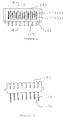
- Figure 1 is a front view of a header of a connector in an application example of the present invention.
- Figure 2 is a plan view of the header in figure 1.
- Figure 3 is a side view of the header in figure 1.
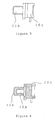
- Figure 4 is a longitudinal cross section view of the housing of header in figure 1.
- Figure 5 is an oblique view of the header in figure 1.
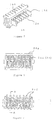
- Figure 6 is a front view of a connector socket as an application example of the present invention.
- Figure 7 is a plan view of the socket in figure 6.
- Figure 8 is a side view of the socket in figure 6.
- Figure 9 is a longitudinal cross section view of the guide groove of the socket in figure 6.
- Figure 10 is an oblique view of the socket in figure 6.
- Figure 11 is a plan view showing the coupled state of a socket and a header.
- Figure 12 is a side view showing the coupled state in figure 11.
- Figures 1-5 show headers 10 of connectors of the present invention.
- the header comprises a housing 10A and multiple contacts 11-12 having elongated post parts, which are mounted at fixed intervals along the longitudinal direction of the housing.
- the contacts consist of post parts 11A, 12A, leg parts 11C, 12C and parts connecting the post parts and the leg parts (not shown in the figures).
- the housing has a nearly rectangular section.
- post parts 11A at both ends of the header are longer than other post parts 12A and also are of wider width than the other post parts. The effect of this will be explained later.
- FIGS. 6-10 show sockets 20 of connectors of the present invention.
- the socket comprises a nearly rectangular housing 20A and multiple contacts 21 for electrical connection to the respective post parts of the header. Those contacts are mounted at a fixed interval along the longitudinal direction of the housing. Further, the contacts are installed inside the housing by removing the terminal leg parts 21C of the contacts so that the contacting parts 21A with the post parts of the header are not stretched out from the housing.
- the socket further has multiple guide grooves 22 for receiving the respective post parts of the header and guiding them to the corresponding contacts of the socket. Those grooves are stretched to the adjoining three planes of the housing of the socket (namely, the adjoining three planes of the housing are opened).
- the contact of the socket comprises a pair of contact pieces 21A (refer to figure 6 and figure 9), terminal part 21C, and a connecting part (not shown in the figures) for connecting the contact pieces and the terminal parts.
- the contact pieces are mutually opposed to receive the post part of the header and also to squeeze the post part into the contact pieces as shown in the figures. Further, mutually opposing projections 21a are formed at the pair of contact pieces 21A, respectively.
- Figures 11 and 12 show a connected state of the header and the socket.
- the post parts of the contacts of the header are passed through the guide grooves of the socket, received at the contact pieces of the socket and squeezed into the contact pieces to connect electrically both parts.
- the socket is pre-attached to, for instance, a battery unit although it is not shown in the figure and the terminals of the contact is connected to the electrode of the unit. Further, the header is mounted on, for instance, printed boards through the leg part of the contact although it is not shown in the figure.
- the guide grooves of the connector socket in the present invention are formed in such a manner to extend to the mutually adjoining three planes of the housing of the socket, it is possible to connect the post parts of the header to the contacts of the socket at a state in straight line form or mutually crossed form. Therefore, the freedom of connecting direction in connecting the header to the socket is large.
- the longer and wider post parts are first guided through the guide grooves of the socket to connect to opposite contacts, regardless of the connecting direction when the post parts are connected to the contacts of the socket.
- both male and female connectors socketet and header
- the contacts having longer post parts are used as grounding terminals, the electrical safety is improved since the grounding terminals are first connected to the contacts of the socket.
- the contacting part of the contacts of the socket with the post parts of the header is not exposed to the outside of the socket in the connector of the present invention, the contact point of the contact of the socket is not exposed to the outside of the housing regardless of the connection state of the socket and the header. Therefore, even when the socket is attached to, for instance, a unit having a large-capacity battery, the safety in handling is secured without short circuiting.
Applications Claiming Priority (3)
| Application Number | Priority Date | Filing Date | Title |
|---|---|---|---|
| JP12737/95 | 1995-12-01 | ||
| JP1995012737U JP3025387U (ja) | 1995-12-01 | 1995-12-01 | コネクタ |
| JP1273795 | 1995-12-01 |
Publications (3)
| Publication Number | Publication Date |
|---|---|
| EP0777305A2 true EP0777305A2 (fr) | 1997-06-04 |
| EP0777305A3 EP0777305A3 (fr) | 1998-05-20 |
| EP0777305B1 EP0777305B1 (fr) | 2002-06-12 |
Family
ID=11813751
Family Applications (1)
| Application Number | Title | Priority Date | Filing Date |
|---|---|---|---|
| EP96308710A Expired - Lifetime EP0777305B1 (fr) | 1995-12-01 | 1996-12-02 | Connecteur |
Country Status (5)
| Country | Link |
|---|---|
| US (1) | US6027353A (fr) |
| EP (1) | EP0777305B1 (fr) |
| JP (1) | JP3025387U (fr) |
| CA (1) | CA2191544A1 (fr) |
| DE (1) | DE69621746T2 (fr) |
Cited By (1)
| Publication number | Priority date | Publication date | Assignee | Title |
|---|---|---|---|---|
| US7435133B2 (en) * | 2001-07-25 | 2008-10-14 | Sony Corporation | Battery device having a casing with plural terminal grooves wherein opposing contact pieces of each terminal member are disposed in each terminal groove |
Families Citing this family (7)
| Publication number | Priority date | Publication date | Assignee | Title |
|---|---|---|---|---|
| US6461178B1 (en) * | 2001-10-19 | 2002-10-08 | Speed Tech Corp. | Electric connector and adapter arrangement |
| CN2862419Y (zh) * | 2005-07-02 | 2007-01-24 | 富士康(昆山)电脑接插件有限公司 | 电连接器组件 |
| CN200959434Y (zh) * | 2006-08-15 | 2007-10-10 | 富士康(昆山)电脑接插件有限公司 | 电连接器 |
| US7802994B1 (en) * | 2009-04-06 | 2010-09-28 | Cheng Uei Precision Industry Co., Ltd. | Combination of connector assembly and two printed circuit boards |
| US20110130043A1 (en) * | 2009-11-27 | 2011-06-02 | Wan-Tien Chen | Combination of socket and plug for battery connector |
| JP4908621B1 (ja) * | 2010-10-15 | 2012-04-04 | 株式会社東芝 | 電子機器 |
| CN105702903B (zh) * | 2014-12-09 | 2020-10-27 | 安普泰科电子韩国有限公司 | 电池用连接器组件,电池组及其制造方法 |
Family Cites Families (5)
| Publication number | Priority date | Publication date | Assignee | Title |
|---|---|---|---|---|
| JPS6079681A (ja) * | 1983-09-28 | 1985-05-07 | モレツクス・インコ−ポレ−テツド | ヒンジ付電気コネクタ− |
| US4655522A (en) * | 1984-12-24 | 1987-04-07 | Amp Incorporated | Electrical terminal receptacle |
| US4867690A (en) * | 1988-06-17 | 1989-09-19 | Amp Incorporated | Electrical connector system |
| TW270248B (fr) * | 1993-11-17 | 1996-02-11 | Whitaker Corp | |
| US5542850A (en) * | 1994-06-30 | 1996-08-06 | The Whitaker Corporation | Pivotal electrical connector |
-
1995
- 1995-12-01 JP JP1995012737U patent/JP3025387U/ja not_active Expired - Lifetime
-
1996
- 1996-11-27 US US08/757,363 patent/US6027353A/en not_active Expired - Lifetime
- 1996-11-29 CA CA002191544A patent/CA2191544A1/fr not_active Abandoned
- 1996-12-02 DE DE69621746T patent/DE69621746T2/de not_active Expired - Lifetime
- 1996-12-02 EP EP96308710A patent/EP0777305B1/fr not_active Expired - Lifetime
Non-Patent Citations (1)
| Title |
|---|
| None |
Cited By (2)
| Publication number | Priority date | Publication date | Assignee | Title |
|---|---|---|---|---|
| US7435133B2 (en) * | 2001-07-25 | 2008-10-14 | Sony Corporation | Battery device having a casing with plural terminal grooves wherein opposing contact pieces of each terminal member are disposed in each terminal groove |
| US7556526B2 (en) | 2001-07-25 | 2009-07-07 | Sony Corporation | Structures of terminals and component-to-be-loaded |
Also Published As
| Publication number | Publication date |
|---|---|
| DE69621746D1 (de) | 2002-07-18 |
| JP3025387U (ja) | 1996-06-11 |
| EP0777305B1 (fr) | 2002-06-12 |
| US6027353A (en) | 2000-02-22 |
| DE69621746T2 (de) | 2002-10-24 |
| EP0777305A3 (fr) | 1998-05-20 |
| CA2191544A1 (fr) | 1997-06-02 |
Similar Documents
| Publication | Publication Date | Title |
|---|---|---|
| US5466171A (en) | Polarizing system for a blind mating electrical connector assembly | |
| US5145386A (en) | Low profile electrical connector | |
| US5582519A (en) | Make-first-break-last ground connections | |
| US5207603A (en) | Dual thickness blade type electrical terminal | |
| US5188535A (en) | Low profile electrical connector | |
| US5692928A (en) | Electrical connector having terminals with improved retention means | |
| EP0758492B1 (fr) | Borne electrique connue pour recevoir des conducteurs superposes selon le principe du contact autodenudant | |
| EP0717463A2 (fr) | Assemblage de connecteur électrique à profil bas monté en surface | |
| US7261579B2 (en) | Wire-to-board connector | |
| EP0706240A1 (fr) | Connecteurs électriques entre deux plaquettes à circuits imprimés | |
| US6039590A (en) | Electrical connector with relatively movable two-part housing | |
| US4384754A (en) | Multi-plane connectors | |
| US20070254521A1 (en) | Insulation displacement terminal | |
| KR870001865B1 (ko) | 리브 케이지형 단자 | |
| US7976345B2 (en) | Electrical contact assembly and method of manufacturing thereof | |
| EP0795930B1 (fr) | Contact électrique recevant une broche avec une force de contact élevée | |
| EP0512207A1 (fr) | Terminal hermaphrodite | |
| EP0777305A2 (fr) | Connecteur | |
| US6629853B2 (en) | Self-aligning power connector system | |
| US5412271A (en) | Small sized electric motor equipped with an electric connector | |
| US6821164B2 (en) | Connector assembly comprising a tab-receiving insulated spring sleeve and a dual contact with pairs of spaced apart contact members and tails | |
| CN212991386U (zh) | 一种自短路连接器以及对应的连接器组件和插接端子 | |
| US5722839A (en) | Electrical connector for horizontal insertion of a CPU module therein | |
| CN2305793Y (zh) | 板对板连接器组件 | |
| US6341982B1 (en) | Branching apparatus |
Legal Events
| Date | Code | Title | Description |
|---|---|---|---|
| PUAI | Public reference made under article 153(3) epc to a published international application that has entered the european phase |
Free format text: ORIGINAL CODE: 0009012 |
|
| AK | Designated contracting states |
Kind code of ref document: A2 Designated state(s): BE CH DE ES FR GB IT LI LU NL SE |
|
| PUAL | Search report despatched |
Free format text: ORIGINAL CODE: 0009013 |
|
| AK | Designated contracting states |
Kind code of ref document: A3 Designated state(s): BE CH DE ES FR GB IT LI LU NL SE |
|
| 17P | Request for examination filed |
Effective date: 19981028 |
|
| 17Q | First examination report despatched |
Effective date: 19990315 |
|
| GRAG | Despatch of communication of intention to grant |
Free format text: ORIGINAL CODE: EPIDOS AGRA |
|
| GRAG | Despatch of communication of intention to grant |
Free format text: ORIGINAL CODE: EPIDOS AGRA |
|
| GRAH | Despatch of communication of intention to grant a patent |
Free format text: ORIGINAL CODE: EPIDOS IGRA |
|
| GRAH | Despatch of communication of intention to grant a patent |
Free format text: ORIGINAL CODE: EPIDOS IGRA |
|
| RAP1 | Party data changed (applicant data changed or rights of an application transferred) |
Owner name: THOMAS & BETTS CORPORATION |
|
| GRAA | (expected) grant |
Free format text: ORIGINAL CODE: 0009210 |
|
| RIC1 | Information provided on ipc code assigned before grant |
Free format text: 7H 01R 12/18 A, 7H 01R 24/00 B |
|
| AK | Designated contracting states |
Kind code of ref document: B1 Designated state(s): BE CH DE ES FR GB IT LI LU NL SE |
|
| PG25 | Lapsed in a contracting state [announced via postgrant information from national office to epo] |
Ref country code: NL Free format text: LAPSE BECAUSE OF FAILURE TO SUBMIT A TRANSLATION OF THE DESCRIPTION OR TO PAY THE FEE WITHIN THE PRESCRIBED TIME-LIMIT Effective date: 20020612 Ref country code: LI Free format text: LAPSE BECAUSE OF FAILURE TO SUBMIT A TRANSLATION OF THE DESCRIPTION OR TO PAY THE FEE WITHIN THE PRESCRIBED TIME-LIMIT Effective date: 20020612 Ref country code: CH Free format text: LAPSE BECAUSE OF FAILURE TO SUBMIT A TRANSLATION OF THE DESCRIPTION OR TO PAY THE FEE WITHIN THE PRESCRIBED TIME-LIMIT Effective date: 20020612 Ref country code: BE Free format text: LAPSE BECAUSE OF FAILURE TO SUBMIT A TRANSLATION OF THE DESCRIPTION OR TO PAY THE FEE WITHIN THE PRESCRIBED TIME-LIMIT Effective date: 20020612 |
|
| REG | Reference to a national code |
Ref country code: GB Ref legal event code: FG4D |
|
| REG | Reference to a national code |
Ref country code: CH Ref legal event code: EP |
|
| REF | Corresponds to: |
Ref document number: 69621746 Country of ref document: DE Date of ref document: 20020718 |
|
| PG25 | Lapsed in a contracting state [announced via postgrant information from national office to epo] |
Ref country code: SE Free format text: LAPSE BECAUSE OF FAILURE TO SUBMIT A TRANSLATION OF THE DESCRIPTION OR TO PAY THE FEE WITHIN THE PRESCRIBED TIME-LIMIT Effective date: 20020912 |
|
| NLV1 | Nl: lapsed or annulled due to failure to fulfill the requirements of art. 29p and 29m of the patents act | ||
| ET | Fr: translation filed | ||
| PG25 | Lapsed in a contracting state [announced via postgrant information from national office to epo] |
Ref country code: LU Free format text: LAPSE BECAUSE OF NON-PAYMENT OF DUE FEES Effective date: 20021202 |
|
| PG25 | Lapsed in a contracting state [announced via postgrant information from national office to epo] |
Ref country code: ES Free format text: LAPSE BECAUSE OF FAILURE TO SUBMIT A TRANSLATION OF THE DESCRIPTION OR TO PAY THE FEE WITHIN THE PRESCRIBED TIME-LIMIT Effective date: 20021220 |
|
| REG | Reference to a national code |
Ref country code: CH Ref legal event code: PL |
|
| PLBE | No opposition filed within time limit |
Free format text: ORIGINAL CODE: 0009261 |
|
| STAA | Information on the status of an ep patent application or granted ep patent |
Free format text: STATUS: NO OPPOSITION FILED WITHIN TIME LIMIT |
|
| 26N | No opposition filed |
Effective date: 20030313 |
|
| REG | Reference to a national code |
Ref country code: FR Ref legal event code: PLFP Year of fee payment: 20 |
|
| PGFP | Annual fee paid to national office [announced via postgrant information from national office to epo] |
Ref country code: GB Payment date: 20151229 Year of fee payment: 20 |
|
| PGFP | Annual fee paid to national office [announced via postgrant information from national office to epo] |
Ref country code: FR Payment date: 20151217 Year of fee payment: 20 |
|
| PGFP | Annual fee paid to national office [announced via postgrant information from national office to epo] |
Ref country code: DE Payment date: 20151229 Year of fee payment: 20 |
|
| REG | Reference to a national code |
Ref country code: DE Ref legal event code: R071 Ref document number: 69621746 Country of ref document: DE |
|
| REG | Reference to a national code |
Ref country code: GB Ref legal event code: PE20 Expiry date: 20161201 |
|
| PG25 | Lapsed in a contracting state [announced via postgrant information from national office to epo] |
Ref country code: IT Free format text: LAPSE BECAUSE OF NON-PAYMENT OF DUE FEES Effective date: 20151202 |
|
| PG25 | Lapsed in a contracting state [announced via postgrant information from national office to epo] |
Ref country code: GB Free format text: LAPSE BECAUSE OF EXPIRATION OF PROTECTION Effective date: 20161201 |
|
| PG25 | Lapsed in a contracting state [announced via postgrant information from national office to epo] |
Ref country code: IT Free format text: LAPSE BECAUSE OF NON-PAYMENT OF DUE FEES Effective date: 20151202 |
|
| PGFP | Annual fee paid to national office [announced via postgrant information from national office to epo] |
Ref country code: IT Payment date: 20151222 Year of fee payment: 20 |
|
| PGRI | Patent reinstated in contracting state [announced from national office to epo] |
Ref country code: IT Effective date: 20170710 |