EP0777286B1 - Implantable battery powered apparatus - Google Patents
Implantable battery powered apparatus Download PDFInfo
- Publication number
- EP0777286B1 EP0777286B1 EP95250273A EP95250273A EP0777286B1 EP 0777286 B1 EP0777286 B1 EP 0777286B1 EP 95250273 A EP95250273 A EP 95250273A EP 95250273 A EP95250273 A EP 95250273A EP 0777286 B1 EP0777286 B1 EP 0777286B1
- Authority
- EP
- European Patent Office
- Prior art keywords
- battery
- voltage
- tap
- resistance
- input
- Prior art date
- Legal status (The legal status is an assumption and is not a legal conclusion. Google has not performed a legal analysis and makes no representation as to the accuracy of the status listed.)
- Expired - Lifetime
Links
Images


Classifications
-
- H—ELECTRICITY
- H01—ELECTRIC ELEMENTS
- H01M—PROCESSES OR MEANS, e.g. BATTERIES, FOR THE DIRECT CONVERSION OF CHEMICAL ENERGY INTO ELECTRICAL ENERGY
- H01M10/00—Secondary cells; Manufacture thereof
- H01M10/05—Accumulators with non-aqueous electrolyte
-
- A—HUMAN NECESSITIES
- A61—MEDICAL OR VETERINARY SCIENCE; HYGIENE
- A61N—ELECTROTHERAPY; MAGNETOTHERAPY; RADIATION THERAPY; ULTRASOUND THERAPY
- A61N1/00—Electrotherapy; Circuits therefor
- A61N1/18—Applying electric currents by contact electrodes
- A61N1/32—Applying electric currents by contact electrodes alternating or intermittent currents
- A61N1/36—Applying electric currents by contact electrodes alternating or intermittent currents for stimulation
- A61N1/372—Arrangements in connection with the implantation of stimulators
- A61N1/378—Electrical supply
-
- H—ELECTRICITY
- H01—ELECTRIC ELEMENTS
- H01M—PROCESSES OR MEANS, e.g. BATTERIES, FOR THE DIRECT CONVERSION OF CHEMICAL ENERGY INTO ELECTRICAL ENERGY
- H01M10/00—Secondary cells; Manufacture thereof
- H01M10/42—Methods or arrangements for servicing or maintenance of secondary cells or secondary half-cells
- H01M10/425—Structural combination with electronic components, e.g. electronic circuits integrated to the outside of the casing
-
- H—ELECTRICITY
- H01—ELECTRIC ELEMENTS
- H01M—PROCESSES OR MEANS, e.g. BATTERIES, FOR THE DIRECT CONVERSION OF CHEMICAL ENERGY INTO ELECTRICAL ENERGY
- H01M6/00—Primary cells; Manufacture thereof
- H01M6/50—Methods or arrangements for servicing or maintenance, e.g. for maintaining operating temperature
-
- H—ELECTRICITY
- H01—ELECTRIC ELEMENTS
- H01M—PROCESSES OR MEANS, e.g. BATTERIES, FOR THE DIRECT CONVERSION OF CHEMICAL ENERGY INTO ELECTRICAL ENERGY
- H01M2200/00—Safety devices for primary or secondary batteries
-
- H—ELECTRICITY
- H01—ELECTRIC ELEMENTS
- H01M—PROCESSES OR MEANS, e.g. BATTERIES, FOR THE DIRECT CONVERSION OF CHEMICAL ENERGY INTO ELECTRICAL ENERGY
- H01M6/00—Primary cells; Manufacture thereof
- H01M6/04—Cells with aqueous electrolyte
- H01M6/06—Dry cells, i.e. cells wherein the electrolyte is rendered non-fluid
- H01M6/12—Dry cells, i.e. cells wherein the electrolyte is rendered non-fluid with flat electrodes
-
- H—ELECTRICITY
- H01—ELECTRIC ELEMENTS
- H01M—PROCESSES OR MEANS, e.g. BATTERIES, FOR THE DIRECT CONVERSION OF CHEMICAL ENERGY INTO ELECTRICAL ENERGY
- H01M6/00—Primary cells; Manufacture thereof
- H01M6/14—Cells with non-aqueous electrolyte
- H01M6/16—Cells with non-aqueous electrolyte with organic electrolyte
- H01M6/162—Cells with non-aqueous electrolyte with organic electrolyte characterised by the electrolyte
- H01M6/164—Cells with non-aqueous electrolyte with organic electrolyte characterised by the electrolyte by the solvent
-
- H—ELECTRICITY
- H01—ELECTRIC ELEMENTS
- H01M—PROCESSES OR MEANS, e.g. BATTERIES, FOR THE DIRECT CONVERSION OF CHEMICAL ENERGY INTO ELECTRICAL ENERGY
- H01M6/00—Primary cells; Manufacture thereof
- H01M6/42—Grouping of primary cells into batteries
-
- H—ELECTRICITY
- H01—ELECTRIC ELEMENTS
- H01M—PROCESSES OR MEANS, e.g. BATTERIES, FOR THE DIRECT CONVERSION OF CHEMICAL ENERGY INTO ELECTRICAL ENERGY
- H01M6/00—Primary cells; Manufacture thereof
- H01M6/50—Methods or arrangements for servicing or maintenance, e.g. for maintaining operating temperature
- H01M6/5011—Methods or arrangements for servicing or maintenance, e.g. for maintaining operating temperature for several cells simultaneously or successively
- H01M6/5016—Multimode utilisation
-
- Y—GENERAL TAGGING OF NEW TECHNOLOGICAL DEVELOPMENTS; GENERAL TAGGING OF CROSS-SECTIONAL TECHNOLOGIES SPANNING OVER SEVERAL SECTIONS OF THE IPC; TECHNICAL SUBJECTS COVERED BY FORMER USPC CROSS-REFERENCE ART COLLECTIONS [XRACs] AND DIGESTS
- Y02—TECHNOLOGIES OR APPLICATIONS FOR MITIGATION OR ADAPTATION AGAINST CLIMATE CHANGE
- Y02E—REDUCTION OF GREENHOUSE GAS [GHG] EMISSIONS, RELATED TO ENERGY GENERATION, TRANSMISSION OR DISTRIBUTION
- Y02E60/00—Enabling technologies; Technologies with a potential or indirect contribution to GHG emissions mitigation
- Y02E60/10—Energy storage using batteries
Definitions
- They are battery operated implantable medical devices known, which is a measuring device for determining the Have the battery charge level.
- the known battery has one Area with an increased initial voltage. After a discharge of the battery in the amount of approx. 10% of the total energy the open circuit voltage drops almost suddenly the operating voltage. The open circuit voltage remains on this level almost constant until the battery is approx. 90% gave up their total energy through discharge. Subsequently the open circuit voltage drops almost suddenly a final voltage that is significantly below the operating voltage lies, but sufficient to operate the device. This Final voltage is approximately constant until the battery has lost all of its usable residual energy. Then sinks the open circuit voltage also jumped almost to zero from.
- the arrangement according to the invention essentially consists of a battery, a measuring device for determining the State of charge of the battery and an electrical consumer, for example the pulse generator of a pacemaker.
- the electrical consumer is connected to the power supply connected to the first and the second voltage tap and thus has the entire drop over the battery Voltage as supply voltage.
- the measuring device evaluates and generates the battery voltage a battery status signal corresponding to the state of charge. For this purpose, the measuring device measures the whole the battery voltage drop and compares it measured value with the discrete voltage values that the Reflect the state of charge of the battery.
- the measuring device evaluates the entire over the Falling voltage and thereby reaches a greatest possible accuracy.
- Threshold element Generated from the output signal of the measuring circuit Threshold element the battery status signal. This points the threshold value element has one or more threshold values. Depending on the position of the output signal of the measuring circuit relative to the threshold value (s) it becomes Battery status signal generated.
- the first threshold lies between the initial voltage and the operating voltage of the battery. Exceeding of the first threshold characterizes an almost completely charged battery.
- the second threshold lies between the operating voltage and the final voltage of the battery. Is the output signal the measuring circuit between the first and the second Threshold, the battery is normal Discharge area, i.e. the battery is not more fully loaded, but sufficient for a safe one Business.
- the third threshold lies between the final voltage and Zero.
- the output signal of the measuring circuit is between the second and the third threshold, so is the battery in a final phase in which the battery is short stands before their complete exhaustion.
- the battery status signal generated by the threshold value element So has four possible states, the discharge state mark the battery: full, almost full, almost empty and empty.
- the battery condition a battery in an implanted device advantageously be checked non-invasively.
- the pulse rate and / or the pulse amplitude lowers when the battery status signal is an almost empty battery signals. This will extend the life of the arrangement extended.
- the housing is the battery electrically conductive with the third voltage tap connected, which is therefore at ground potential.
- the one simple insulation fault maximum occurring fault voltage is thereby - with one in the middle between the first and the third voltage tap arranged third Voltage tap - to half the total voltage of the Battery limited.
- the consumer 6 is with the first and the second voltage tap electrically connected and thus has over the entire voltage drop across the battery.
- the threshold value element 5 has three threshold values and generates them a battery condition signal that depends on the location of the output signal the measuring circuit relative to the threshold values depends.
- the first threshold is between the initial voltage and the operating voltage of the battery; the second Threshold lies between the operating voltage and the Final voltage and the third threshold lies between the Final voltage and zero. If the battery voltage is above of the first threshold value, the battery status signal signals a fully charged battery; sinks the battery voltage below the first threshold, so signaled the battery status signal is a full battery; the battery voltage drops further below the second Threshold value, so signals the battery status signal an almost empty battery; when the battery voltage drops this signals below the third threshold Battery condition signal finally a completely drained Battery.
- the measuring circuit 4 consists essentially of an operational amplifier OP and four resistors R 1 , R 2 , R 3 and R 4 .
- the operational amplifier works as a subtractor, which subtracts the voltage U 1 from the voltage (-U 2 ), that is to say is operated here as an adder.
- the level of the output signal U A of the measuring circuit 4 can be adapted to the input of the threshold element 5.
- Figure 3 shows a further embodiment of the in Figure 1 measuring circuit 4 shown in detail as a circuit diagram.
- circuit overlaps - like that shown in Figure 2 Circuit - the change related to the reference potential of the first and second potential.
- This voltage swing is the transistor T the operational amplifier OP2 fed.
- the operational amplifier OP2 amplifies the voltage swing and outputs an output signal U A at the output 11 which is approximately proportional to the entire voltage swing.
- Figure 4 shows an embodiment of that shown in Figure 1 Battery with two cells and two accordingly Electrode packages, each in a compartment of a housing 15 are housed.
- Each of the two electrode packs has three as electrodes Cathode plates 12 and 13 and four anode plates 16, 17, 18, 19 or 20, 21, 22, 23 of the same size, which in the Are arranged in parallel so that each cathode plate 12, 13 of two anode plates 16, 17, 18, 19, 20, 21, 22, 23 is adjacent. Electrode packages are also conceivable with 4 cathodes and 5 anodes etc.
- the cathode plates 12, 13 and the anode plates 16, 17, 18, 19, 20, 21, 22, 23 have a rectangular shape with a across the depth essentially uniform width.
- the anode plates 16 belonging to an electrode packet, 17, 18, 19 and 20, 21, 22, 23 are each by a Anode connectors 24 and 25 are electrically conductive with one another connected, while belonging to an electrode package Cathode plates 12 and 13 each by a cathode connector 14 and 15 electrically connected to each other are.
- the capacity of a cell is determined by the size of the Surface of the electrode plates 12, 13, 16, 17, 18, 19, 20, 21, 22, 23 and the number of plates connected in parallel influenced.
- the anode connector 25 of the first electrode pack and the Cathode connectors 15 of the second electrode package are electrical against each other and the housing 26 and are isolated as a pin through a glass bushing in the lid 29, 30 led out.
- the battery as a whole is hermetically sealed.
- Figure 5 shows a battery with two battery cells and corresponding to two electrode packs, each in one Compartment of a housing are housed.
- Each electrode packet has one as electrodes Cathode plate 31 and 32 and two anode plates 33, 34 and 35, 36 of the same size, the cathode plates 31 and 32 each in the middle between the anode plates 33, 34 and 35, 36 and are arranged parallel to these.
- the distance between the electrode plates 31, 32, 33, 34, 35, 36 is of the same order of magnitude as the thickness of the electrode plates 31, 32, 33, 34, 35, 36, whereby to a good functioning of the loading and unloading ongoing electrochemical processes and on the other optimal use of the available space is guaranteed.
- the housing in the form of two half shells 37, 43 it is advantageously possible to start the Pre-assemble electrode packs and on the partition 39 to fasten and then only the half-shells 37, 43 to be placed on the peripheral edges of the partition 39 and to seal.
- Implementation of the welding work for Contacting of partition 39 and anode connector 40 or Cathode plate 32 is therefore simpler in terms of production technology.
- One on the cathode plate 31 of the second electrode pack attached contact and anode connector 46 of the first Electrode packages are electrically insulated and over one Glass bushings 38 and 45 led out.
- the electrolyte preferably consists of a mixture of propylene carbonate (PC), ethylene carbonate (EC), dimetoxyethane (DME) and LiClO 4 , but other known combinations are also conceivable
- the invention is not limited in its execution the preferred embodiments given above. Rather, a number of variants are conceivable which of the. shown solution also in principle makes use of different types.
Description
Die Erfindung betrifft ein batteriebetriebenes implantierbares medizinisches Gerät mit einer Batterie, einer Meßvorrichtung zur Bestimmung des Ladezustands der Batterie durch Messung der Leerlaufspannung und einem elektrischen Verbraucher gemäß dem Oberbegriff des Anspruchs 1. The invention relates to a battery-operated implantable medical device with a battery, a measuring device to determine the state of charge of the battery by measuring the open circuit voltage and an electrical Consumer according to the preamble of claim 1.
Es sind batteriebetriebene implantierbare medizinische Geräte bekannt, die eine Meßvorrichtung zur Bestimmung des Ladezustands der Batterie aufweisen.They are battery operated implantable medical devices known, which is a measuring device for determining the Have the battery charge level.
In der US-PS 3,757,793 ist ein durch eine Batterie betriebener Herzschrittmacher beschrieben, bei dem eine Bestimmung des Ladezustands der Batterie durch Messung der Leerlaufspannung vorgesehen ist. Die Leerlaufspannung nimmt dabei während der Entladung stufenweise bis auf Null ab.In US-PS 3,757,793 is a battery operated Pacemaker described in which a determination the state of charge of the battery by measuring the open circuit voltage is provided. The open circuit voltage increases thereby gradually decreasing to zero during the discharge.
Zu Beginn der Entladung weist die vorbekannte Batterie einen Bereich mit einer erhöhten Anfangsspannung auf. Nach einer Entladung der Batterie in Höhe von ca. 10% der Gesamtenergie sinkt die Leerlaufspannung nahezu sprunghaft auf die Betriebsspannung ab. Die Leerlaufspannung bleibt auf diesem Niveau annähernd konstant, bis die Batterie ca. 90% ihrer Gesamtenergie durch Entladung abgegeben hat. Anschließend sinkt die Leerlaufspannung nahezu sprunghaft auf eine Endspannung ab, die deutlich unterhalb der Betriebsspannung liegt, aber zum Betrieb des Geräts ausreicht. Diese Endspannung ist annähernd konstant, bis die Batterie ihre gesamte nutzbare Restenergie verloren hat. Dann sinkt die Leerlaufspannung ebenfalls nahezu sprunghaft auf Null ab.At the beginning of the discharge, the known battery has one Area with an increased initial voltage. After a discharge of the battery in the amount of approx. 10% of the total energy the open circuit voltage drops almost suddenly the operating voltage. The open circuit voltage remains on this level almost constant until the battery is approx. 90% gave up their total energy through discharge. Subsequently the open circuit voltage drops almost suddenly a final voltage that is significantly below the operating voltage lies, but sufficient to operate the device. This Final voltage is approximately constant until the battery has lost all of its usable residual energy. Then sinks the open circuit voltage also jumped almost to zero from.
Die vorbekannte Batterie ermöglicht es auf einfache Weise, den Ladezustand der Batterie zu ermitteln. Hierzu wird die Leerlaufspannung gemessen und mit den Werten der Anfangsspannung, der Betriebsspannung und der Endspannung verglichen.The known battery makes it easy to determine the state of charge of the battery. For this, the Open circuit voltage measured and with the values of the initial voltage, the operating voltage and the final voltage compared.
Es kann auf diese Weise sichergestellt werden, daß nur vollständig geladene Batterien implantiert werden. In this way it can be ensured that only fully charged batteries are implanted.
Darüberhinaus ist es möglich, das bevorstehende Ende der Lebensdauer der Batterie zu einem Zeitpunkt zu erkennen, in dem die verbleibende Restenergie zur Aufrechterhaltung des Betriebs für einen zur Durchführung eines Therapievorgangs notwendigen Mindestzeitraum noch ausreicht. Während dieses Zeitraums kann z.B. die Batterie ausgetauscht werden. Es ist deshalb möglich, die Energie der Batterie nahezu vollständig auszunutzen, da das Ende der Lebensdauer zuverlässig vorhersehbar ist und somit diesbezüglich keine Sicherheitsreserven notwendig sind.Furthermore, it is possible to mark the upcoming end of the Recognize battery life at a time in which the remaining energy to maintain the Operating for one to perform a therapy necessary minimum period is still sufficient. During this Period can e.g. the battery can be replaced. It It is therefore possible to use the battery energy almost completely exploit because the end of life is reliable is predictable and therefore no safety reserves in this regard are necessary.
Bei der vorbekannten Anordnung tritt jedoch ein Problem auf.However, there is a problem with the prior art arrangement on.
Zur Messung der Leerlaufspannung und zur Bestimmung des Ladezustands aus der gemessenen Spannung ist zumindest im implantierten Zustand des Geräts eine elektronische Schaltung erforderlich. Diese Schaltung benötigt jedoch in der Regel eine symmetrische Spannungsversorgung. Es ist also eine Spannungsversorgung notwendig, die ein Bezugspotential, sowie zwei - bezogen auf das Bezugspotential - unterschiedliche Polaritäten liefert. Dies wird von der bekannten Anordnung nicht geleistet.To measure the open circuit voltage and to determine the State of charge from the measured voltage is at least in the implanted state of the device an electronic circuit required. However, this circuit needs in the Usually a symmetrical power supply. So it is a power supply is necessary that has a reference potential, and two - in relation to the reference potential - different Provides polarities. This is known from the Order not made.
Der Erfindung liegt deshalb insbesondere die Aufgabe zugrunde, ein batteriebetriebenes implantierbares medizinisches Gerät zu schaffen, bei dem die Batterie sowohl die Spannungsversorgung eines elektrischen Verbrauchers als auch die symmetrische Spannungsversorgung einer zur Bestimmung des Ladezustands der Batterie verwendeten Meßvorrichtung ermöglicht. Darüberhinaus soll der hierzu notwendige zusätzliche apparative Aufwand im Hinblick auf die Implantation des Geräts in den menschlichen Körper hinsichtlich des zusätzlichen Gewichts und des zusätzlichen Bauvolumens möglichst gering sein.The invention is therefore based in particular on the object a battery powered implantable medical To create device where the battery is both the voltage supply of an electrical consumer as also the symmetrical power supply for determination the state of charge of the battery used measuring device enables. In addition, the necessary for this additional equipment expenditure with regard to the implantation of the device in terms of the human body the additional weight and the additional construction volume be as small as possible.
Die Aufgabe wird mit den im kennzeichnenden Teil des Anspruchs 1 angegebenen Maßnahmen gelöst.The task is carried out in the characterizing part of the claim 1 specified measures solved.
Die Erfindung schließt die technische Lehre ein, daß eine Batterie eine Reihenschaltung mehrerer Zellen mit drei ein symmetrisches Spannungssystem bildenden Spannungsabgriffen aufweist und eine von dem symmetrischen Spannungssystem versorgte Meßvorrichtung die maximal zwischen den drei Spannungsabgriffen auftretende Spannung auswertet.The invention includes the technical teaching that a Battery a series connection of several cells with three symmetrical voltage system forming voltage taps and one of the symmetrical voltage system supplied measuring device the maximum between the three Voltage taps occurring voltage evaluates.
Die erfindungsgemäße Anordnung besteht im wesentlichen aus einer Batterie, einer Meßvorrichtung zur Bestimmung des Ladezustands der Batterie und einem elektrischen Verbraucher, beispielsweise dem Impulsgeber eines Herzschrittmachers.The arrangement according to the invention essentially consists of a battery, a measuring device for determining the State of charge of the battery and an electrical consumer, for example the pulse generator of a pacemaker.
Die in der erfindungsgemäßen Anordnung enthaltene Batterie gibt - wie die in der US-PS 3,757,793 vorbeschriebene Batterie - in Abhängigkeit von der verbleibenden Restenergie abgestufte diskrete Spannungswerte ab.The battery contained in the arrangement according to the invention there - like the battery described in US Pat. No. 3,757,793 - depending on the remaining energy graded discrete voltage values.
In der Batterie ist eine Reihenschaltung mehrerer Zellen vorgesehen, wodurch sich die Spannungen der einzelnen Zellen addieren. Der Abstand zwischen den diskreten Spannungswerten der Batterie nimmt dadurch ebenfalls zu, wodurch die Unterscheidung der diskreten Spannungswerte und damit die Bestimmung des Ladezustands erleichtert wird.There is a series connection of several cells in the battery provided whereby the tensions of the individual cells add. The distance between the discrete voltage values the battery also increases, causing the Differentiation of the discrete voltage values and thus the Determination of the state of charge is facilitated.
Die Reihenschaltung weist jeweils eine frei Anode und eine freie Katode auf. An der freien Anode ist ein erster Spannungsabgriff und an der freien Katode ein zweiter Spannungsabgriff vorgesehen, so daß ein erstes und ein zweites Potential und damit die gesamte über der Batterie abfallende Spannung abgreifbar ist.The series connection has one free anode and one free cathode. There is a first voltage tap on the free anode and a second voltage tap on the free cathode provided so that a first and a second Potential and thus the total falling over the battery Voltage can be tapped.
Der elektrische Verbraucher ist zur Spannungsversorgung mit dem ersten und dem zweiten Spannungsabgriff verbunden und verfügt dadurch über die gesamte über der Batterie abfallende Spannung als Versorgungsspannung.The electrical consumer is connected to the power supply connected to the first and the second voltage tap and thus has the entire drop over the battery Voltage as supply voltage.
An einer anderen, in der Reihenschaltung zwischen den äußeren Elektroden liegenden Elektrode ist ein dritter Spannungsabgriff vorgesehen. Das Potential dieses dritten Spannungsabgriffs liegt zwischen dem Potential des ersten und des zweiten Spannungsabgriffs und dient als Bezugspotential. Hierdurch entsteht ein symmetrisches Spannungsystem zur Spannungsversorgung der Meßvorrichtung.Another, in the series connection between the outer ones Electrode lying electrode is a third voltage tap intended. The potential of this third voltage tap lies between the potential of the first and the second Voltage tap and serves as a reference potential. Hereby creates a symmetrical voltage system for power supply the measuring device.
Die Meßvorrichtung wertet die Batteriespannung aus und erzeugt entsprechend dem Ladezustand ein Batteriezustandssignal. Hierzu mißt die Meßvorrichtung den gesamten über der Batterie abfallenden Spannungshub und vergleicht den gemessenen Wert mit den diskreten Spannungswerten, die den Ladezustand der Batterie wiederspiegeln.The measuring device evaluates and generates the battery voltage a battery status signal corresponding to the state of charge. For this purpose, the measuring device measures the whole the battery voltage drop and compares it measured value with the discrete voltage values that the Reflect the state of charge of the battery.
Die erfindungsgemäße Anordnung erzielt also drei Hauptwirkungen.The arrangement according to the invention thus achieves three main effects.
Erstens steht für den elektrischen Verbraucher die gesamte an der Batterie abfallende Spannung zur Verfügung.First, the entire stands for the electrical consumer voltage drop across the battery is available.
Zweitens wird ein symmetrisches Spannungssystem zur Versorgung der Meßvorrichtung bereitgestellt.Second, a symmetrical supply voltage system the measuring device provided.
Drittens wertet die Meßvorrichtung die gesamte über der Batterie abfallenden Spannung aus und erreicht dadurch eine größtmögliche Genauigkeit. Third, the measuring device evaluates the entire over the Falling voltage and thereby reaches a greatest possible accuracy.
Mit zunehmender Genauigkeit der Meßvorrichtung sinken die Anforderungen an den Abstand der diskreten Spannungswerte. Bei einer großen Genauigkeit der Meßvorrichtung können so die diskreten Spannungswerte dichter zusammenliegen.With increasing accuracy of the measuring device the decrease Requirements for the distance of the discrete voltage values. With a high accuracy of the measuring device can the discrete voltage values are closer together.
Hierdurch ist es vorteilhaft möglich, die Endspannung nahe an die Betriebsspannung heranzulegen und dadurch die mit der verringerten Endspannung verbundenen negativen Folgen zu minimieren.As a result, it is advantageously possible to approach the final voltage to apply to the operating voltage and thereby the the negative consequences associated with the reduced final voltage to minimize.
Zum Erreichen des beschriebenen stufenförmigen Spannungsverlaufs mit mehreren diskreten Spannungswerten ist ein relativ hoher konstruktiver Aufwand hinsichtlich der Zusammensetzung der Elektroden und des Elektrolyten notwendig, wobei die Erreichung des stufenförmigen Spannungsverlaufs und die Kapazitätsmaximierung teilweise nicht vereinbar sind. Durch die Erhöhung der Genauigkeit der Meßvorrichtung und die daraus resultierenden geringeren Anforderungen an den Abstand der diskreten Spannungswerte der Batterie wird so vorteilhaft der konstruktive Spielraum erhöht.To achieve the step-like voltage curve described with multiple discrete voltage values is one relatively high design effort in terms of composition the electrodes and the electrolyte necessary, the achievement of the step-shaped voltage curve and the capacity maximization partly not compatible are. By increasing the accuracy of the measuring device and the resulting lower requirements the distance of the discrete voltage values of the battery so the constructive scope is advantageously increased.
In einer bevorzugten Ausführungsform der Erfindung besteht die Meßschaltung aus einem Addierer, der die Spannung zwischen dem ersten Potential und dem Bezugspotential sowie zwischen dem Bezugspotential und dem zweiten Potential addiert.In a preferred embodiment of the invention the measuring circuit from an adder, the voltage between the first potential and the reference potential as well added between the reference potential and the second potential.
Auf diese Weise wird vorteilhaft die gesamte über der Batterie abfallende Spannung ausgewertet.In this way, the entire over the battery is advantageous falling voltage evaluated.
Aus dem Ausgangssignal der Meßschaltung erzeugt ein Schwellwertglied das Batteriezustandssignal. Hierzu weist das Schwellwertglied einen oder mehrere Schwellwerte auf. In Abhängigkeit von der Lage des Ausgangssignals der Meßschaltung relativ zu dem oder den Schwellwerten wird das Batteriezustandssignal erzeugt.Generated from the output signal of the measuring circuit Threshold element the battery status signal. This points the threshold value element has one or more threshold values. Depending on the position of the output signal of the measuring circuit relative to the threshold value (s) it becomes Battery status signal generated.
In einer bevorzugten Ausführungsform der Erfindung weist das Schwellwertglied drei Schwellwerte auf.In a preferred embodiment of the invention the threshold element has three threshold values.
Der erste Schwellwert liegt zwischen der Anfangs spannung und der Betriebsspannung der Batterie. Ein Überschreiten des ersten Schwellwertes kennzeichnet eine nahezu vollständig geladene Batterie.The first threshold lies between the initial voltage and the operating voltage of the battery. Exceeding of the first threshold characterizes an almost completely charged battery.
Der zweite Schwellwert liegt zwischen der Betriebsspannung und der Endspannung der Batterie. Liegt das Ausgangssignal der Meßschaltung zwischen dem ersten und dem zweiten Schwellwert, so befindet sich die Batterie in einem normalen Entladungsbereich, d.h. die Batterie ist zwar nicht mehr vollständig geladen, aber ausreichend für einen sicheren Betrieb.The second threshold lies between the operating voltage and the final voltage of the battery. Is the output signal the measuring circuit between the first and the second Threshold, the battery is normal Discharge area, i.e. the battery is not more fully loaded, but sufficient for a safe one Business.
Der dritte Schwellwert liegt zwischen der Endspannung und Null. Liegt das Ausgangssignal der Meßschaltung zwischen dem zweiten und dem dritten Schwellwert, so befindet sich die Batterie in einer Endphase, in der die Batterie kurz vor ihrer völligen Erschöpfung steht.The third threshold lies between the final voltage and Zero. The output signal of the measuring circuit is between the second and the third threshold, so is the battery in a final phase in which the battery is short stands before their complete exhaustion.
Ein Unterschreiten des dritten Schwellwertes kennzeichnet eine vollständig entladene Batterie.Indicates that the value falls below the third threshold a fully discharged battery.
Das von dem Schwellwertglied erzeugte Batteriezustandssignal weist also vier mögliche Zustände auf, die den Entladezustand der Batterie kennzeichnen: voll, fast voll, fast leer und leer.The battery status signal generated by the threshold value element So has four possible states, the discharge state mark the battery: full, almost full, almost empty and empty.
Eine Variante der Erfindung sieht eine Telemetrieübertragung des Ausgangssignals der Meßschaltung oder des Batteriezustandssignals an eine außerhalb des Körpers befindliche Empfangseinheit vor. Hierzu weist die Meßvorrichtung eine Sende-/Empfangseinheit auf. Die Übertragung kann beispielsweise drahtlos durch elektromagnetische Wellen erfolgen. Der Empfang erfolgt vorzugsweise durch Auflegen eines Antennenelements auf die Körperoberfläche in der Nähe der Sendeeinheit. Hierdurch kann die erforderliche Sendeleistung und damit der Energieverbrauch des Senders niedrig gehalten werden.A variant of the invention provides telemetry transmission the output signal of the measuring circuit or the battery status signal to someone outside the body Receiving unit. For this purpose, the measuring device a transmitter / receiver unit. The transmission can, for example done wirelessly by electromagnetic waves. The reception is preferably carried out by hanging up a Antenna element on the body surface near the Transmitter unit. This allows the required transmission power and thus the energy consumption of the transmitter is low being held.
In einer Variante der Erfindung weist die Sende-/Empfangseinheit zwei Modi auf. Im normalen Betrieb arbeitet die Sende-/Empfangseinheit als Empfänger. Wird von einer außerhalb des Körpers befindlichen Sendeeinheit ein Aktivierungssignal gesendet, so schaltet die Sende-/Empfangseinheit in den Sendemodus um und überträgt das Batteriezustandssignal oder das Ausgangssignal der Meßschaltung an eine außerhalb des Körpers befindliche Empfangseinheit. Anschließend wird wieder in den Empfangsmodus zurückgeschaltet. Auf diese Weise wird vorteilhaft der Energieverbrauch minimiert, da der während des Sendebetriebs relativ hohe Energieverbrauch nur dann anfällt, wenn dies tatsächlich erforderlich ist.In a variant of the invention, the transmitter / receiver unit has two modes. It works in normal operation Transmitter / receiver unit as a receiver. Being from an outside the transmitter unit located an activation signal sent, the transmitter / receiver unit switches to transmit mode and transmits the battery status signal or the output signal of the measuring circuit a receiving unit located outside the body. Then the system switches back to receive mode. In this way, energy consumption becomes advantageous minimized, since the relative during the transmission high energy consumption only occurs when this is actually the case is required.
Durch die Telemetrieübertragung kann der Batteriezustand einer in einem implantierten Gerät befindlichen Batterie in vorteilhafter Weise nicht-invasiv überprüft werden.Due to the telemetry transmission, the battery condition a battery in an implanted device advantageously be checked non-invasively.
In einer anderen Variante der Erfindung weist der elektrische Verbraucher eine Steuereinheit auf, die das Batteriezustandssignal auswertet und in Abhängigkeit von dem Ladezustand der Batterie den Stromverbrauch steuert.In another variant of the invention, the electrical Consumers have a control unit that receives the battery status signal evaluates and depending on the state of charge the battery controls power consumption.
Dies kann beispielsweise dadurch geschehen, daß ein Herzschrittmacher die Impulsrate und/oder die Impulsamplitude senkt, wenn das Batteriezustandssignal eine fast leere Batterie signalisiert. Hierdurch wird die Lebensdauer der Anordnung verlängert.This can be done, for example, by using a pacemaker the pulse rate and / or the pulse amplitude lowers when the battery status signal is an almost empty battery signals. This will extend the life of the arrangement extended.
In einer Variante der Erfindung ist das Gehäuse der Batterie elektrisch leitend mit dem dritten Spannungsabgriff verbunden, der somit auf Massepotential liegt. Die bei einem einfachen Isolationsfehler maximal auftretende Fehlerspannung wird dadurch - bei einem mittig zwischen dem ersten und dem zweiten Spannungsabgriff angeordneten dritten Spannungsabgriff - auf die Hälfte der Gesamtspannung der Batterie begrenzt.In a variant of the invention, the housing is the battery electrically conductive with the third voltage tap connected, which is therefore at ground potential. The one simple insulation fault maximum occurring fault voltage is thereby - with one in the middle between the first and the third voltage tap arranged third Voltage tap - to half the total voltage of the Battery limited.
Andere vorteilhafte Weiterbildungen der Erfindung sind in den Unteransprüchen gekennzeichnet bzw. werden nachstehend zusammen mit der Beschreibung der bevorzugten Ausführungen der Erfindung anhand der Figuren näher dargestellt. Es zeigen:
- Figur 1
- als Ausführungsbeispiel der Erfindung eine Anordnung mit einer Batterie, einer Meßschaltung, einem Schwellwertglied sowie einem elektrischen Verbraucher als Blockschaltbild,
- Figur 2
- eine bevorzugte Ausführungsform der in Figur 1 dargestellten Meßschaltung als Schaltbild,
- Figur 3
- eine weitere Ausführungsform der in Figur 1 dargestellten Meßschaltung als Schaltbild,
- Figur 4
- eine bevorzugte Ausführungsform der in Figur 1 dargestellten Batterie detailliert in perspektivischer Darstellung sowie
- Figur 5
- eine weitere Ausführungsform der in Figur 1 dargestellten Batterie detailliert in Querschnittsdarstellung.
- Figure 1
- as an exemplary embodiment of the invention, an arrangement with a battery, a measuring circuit, a threshold value element and an electrical consumer as a block diagram,
- Figure 2
- 1 shows a preferred embodiment of the measuring circuit shown in FIG. 1 as a circuit diagram,
- Figure 3
- 1 shows another embodiment of the measuring circuit shown in FIG. 1 as a circuit diagram,
- Figure 4
- a preferred embodiment of the battery shown in Figure 1 in detail in perspective and
- Figure 5
- a further embodiment of the battery shown in Figure 1 in detail in cross-section.
Die Batterie weist zwei in Reihe geschaltete Zellen 1, 2 auf, wobei die Katode der ersten Zelle 1 und die Anode der zweiten Zelle 2 durch ein Verbindungsstück elektrisch leitend miteinander verbunden sind. An der Anode der ersten Zelle 1 ist ein erster Spannungsabgriff vorgesehen. An der Katode der zweiten Zelle 2 ist ein zweiter Spannungsabgriff vorgesehen. Auf diese Weise ist die gesamte über der Batterie abfallende Spannung abgreifbar.The battery has two cells 1, 2 connected in series on, the cathode of the first cell 1 and the anode of the second cell 2 electrically conductive through a connector are interconnected. On the anode of the first Cell 1 has a first voltage tap. At the The cathode of the second cell 2 is a second voltage tap intended. This way the whole is over the battery falling voltage can be tapped.
Der Verbraucher 6 ist mit dem ersten und dem zweiten Spannungsabgriff elektrisch leitend verbunden und verfügt somit über die gesamte an der Batterie abfallende Spannung.The consumer 6 is with the first and the second voltage tap electrically connected and thus has over the entire voltage drop across the battery.
An dem Verbindungsstück zwischen den Zellen 1, 2 ist ein dritter Spannungsabgriff 3 vorgesehen, an dem ein Bezugspotential abgreifbar ist. Zusammen mit den an dem ersten und dem zweiten Spannungsabgriff abgreifbaren Potentialen steht auf diese Weise eine symmetrische Spannungsversorgung für die Meßvorrichtung 7 zur Verfügung.At the connector between cells 1, 2 is a third voltage tap 3 is provided, at which a reference potential is tapped. Along with those on the first and the second voltage tap potentials in this way there is a symmetrical power supply available for the measuring device 7.
Der dritte Spannungsabgriff 3 ist mit dem Gehäuse der Batterie verbunden. Dadurch ist die bei einem einfachen Isolationsfehler auftretende Kurzschlußspannung auf die Spannung der schadhaften Zelle 1, 2 begrenzt, die ungefähr halb so groß ist wie die gesamte Batteriespannung.The third voltage tap 3 is with the housing of the battery connected. This is the case of a simple insulation fault occurring short circuit voltage to the voltage the defective cell 1, 2 limited to about half as much is the same as the total battery voltage.
Die Meßvorrichtung 7 besteht im wesentlichen aus einer Meßschaltung 4 und einem Schwellwertglied 5.The measuring device 7 consists essentially of a measuring circuit 4 and a threshold element 5.
Die Meßschaltung 4 überlagert die auf das Bezugspotential bezogene Änderung des ersten und des zweiten Potentials additiv und erzeugt daraus ein Ausgangssignal, das dem über der gesamten Batterie abfallenden Spannungshub entspricht. Bei einer Vergrößerung des gesamten Spannungshubs wird auch das Ausgangssignal größer; bei einer Verringerung des gesamten Spannungshubs wird auch das Ausgangssignal kleiner.The measuring circuit 4 is superimposed on the reference potential related change of the first and second potential additive and generates an output signal from it, which the over of the entire battery voltage drop corresponds. If the entire voltage swing is increased, too the output signal larger; with a reduction in the total The output signal becomes smaller as well.
Das Schwellwertglied 5 weist drei Schwellwerte auf und erzeugt ein Batteriezustandssignal, das von der Lage des Ausgangssignals der Meßschaltung relativ zu den Schwellwerten abhängt. Der erste Schwellwerte liegt zwischen der Anfangsspannung und der Betriebsspannung der Batterie; der zweite Schwellwert liegt zwischen der Betriebsspannung und der Endspannung und der dritte Schwellwert liegt zwischen der Endspannung und Null. Liegt die Batteriespannung oberhalb des ersten Schwellwertes, so signalisiert das Batteriezustandssignal eine vollständig gefüllte Batterie; sinkt die Batteriespannung unter den ersten Schwellwert, so signalisiert das Batteriezustandssignal eine volle Batterie; sinkt die Batteriespannung weiter unter den zweiten Schwellwert, so signalisiert das Batteriezustandssignal eine fast leere Batterie; bei einem Absinken der Batteriespannung unter den dritten Schwellwert signalisiert das Batteriezustandssignal schließlich eine vollständig entleerte Batterie.The threshold value element 5 has three threshold values and generates them a battery condition signal that depends on the location of the output signal the measuring circuit relative to the threshold values depends. The first threshold is between the initial voltage and the operating voltage of the battery; the second Threshold lies between the operating voltage and the Final voltage and the third threshold lies between the Final voltage and zero. If the battery voltage is above of the first threshold value, the battery status signal signals a fully charged battery; sinks the battery voltage below the first threshold, so signaled the battery status signal is a full battery; the battery voltage drops further below the second Threshold value, so signals the battery status signal an almost empty battery; when the battery voltage drops this signals below the third threshold Battery condition signal finally a completely drained Battery.
Figur 2 zeigt ein Ausführungsbeispiel der in Figur 1 dargestellten Meßschaltung 4 detailliert als Schaltbild.Figure 2 shows an embodiment of that shown in Figure 1 Measuring circuit 4 in detail as a circuit diagram.
Die Meßschaltung 4 besteht im wesentlichen aus einem Operationsverstärker OP und vier Widerständen R1, R2, R3 und R4.The measuring circuit 4 consists essentially of an operational amplifier OP and four resistors R 1 , R 2 , R 3 and R 4 .
Der Operationsverstärker arbeitet in der dargestellten Anordnung als Subtrahierer, der die Spannung U1 von der Spannung (-U2) subtrahiert, also hier als Addierer betrieben wird.In the arrangement shown, the operational amplifier works as a subtractor, which subtracts the voltage U 1 from the voltage (-U 2 ), that is to say is operated here as an adder.
Die Spannung U1 ist die Spannung zwischen dem ersten Spannungsabgriff 8 und dem dritten Spannungsabgriff 9, während die Spannung U2 die Spannung zwischem dem dritten Spannungsabgriff 9 und dem zweiten Spannungsabgriff 10 ist. Der Addierer bildet also die Summe der über den beiden Zellen abfallenden Spannungen und erzeugt ein der gesamten Batteriespannung proportionales Ausgangssignal UA.The voltage U 1 is the voltage between the first voltage tap 8 and the third voltage tap 9, while the voltage U 2 is the voltage between the third voltage tap 9 and the second voltage tap 10. The adder therefore forms the sum of the voltages dropping across the two cells and generates an output signal U A which is proportional to the total battery voltage.
Für die Ausgangsspannung UA des Addierers gilt:
Zur ordnungsgemäßen Funktion des Addierers müssen die Widerstände
R1, R2, R3 und R4 die Koeffizientenbedingung erfüllen:
Durch eine Variation des Verstärkungsfaktors k läßt sich der Pegel des Ausgangssignals UA der Meßschaltung 4 an den Eingang des Schwellwertgliedes 5 anpassen.By varying the gain factor k, the level of the output signal U A of the measuring circuit 4 can be adapted to the input of the threshold element 5.
Figur 3 zeigt ein weiteres Ausführungsbeispiel der in Figur 1 dargestellten Meßschaltung 4 detailliert als Schaltbild.Figure 3 shows a further embodiment of the in Figure 1 measuring circuit 4 shown in detail as a circuit diagram.
Die Schaltung überlagert - wie die in Figur 2 dargestellte Schaltung - die auf das Bezugspotential bezogene Änderung des ersten und des zweiten Potentials.The circuit overlaps - like that shown in Figure 2 Circuit - the change related to the reference potential of the first and second potential.
Am Eingang der Meßschaltung ist ein Pegelwandler vorgesehen, bestehend aus der Zenerdiode DZ und dem Widerstand R5. Der Pegelwandler bildet die Summe der Spannungen U1 und U2 und verringert diese um die konstante Spannung UZ der Zenerdiode DZ. An dem Widerstand R5 fällt deshalb die Spannung U=U1+U2-UZ ab. Es ist also der gesamte Spannungshub der Batterie an dem Widerstand R5 abgreifbar.A level converter is provided at the input of the measuring circuit, consisting of the Zener diode D Z and the resistor R 5 . The level converter forms the sum of the voltages U 1 and U 2 and reduces this by the constant voltage U Z of the Zener diode D Z. The voltage U = U 1 + U 2 -U Z therefore drops across the resistor R 5 . The entire voltage swing of the battery can thus be tapped at the resistor R 5 .
Dieser Spannungshub wird über den Transistor T dem Operationsverstärker OP2 zugeführt.This voltage swing is the transistor T the operational amplifier OP2 fed.
Der Operationsverstärker OP2 verstärkt den Spannungshub und gibt an dem Ausgang 11 ein Ausgangssignal UA ab, das annähernd proportional dem gesamten Spannungshub ist.The operational amplifier OP2 amplifies the voltage swing and outputs an output signal U A at the output 11 which is approximately proportional to the entire voltage swing.
Durch eine Variation des Verhältnisses der Widerstände R9 und R7 läßt sich der Verstärkungsfaktor des Operationsverstärkers OP2 einstellen und damit der Pegel der Ausgangsspannung UA an den Eingang des Schwellwertgliedes 5 anpassen. Durch eine Vergrößerung des Quotienten aus R9 und R7 läßt sich die Ausgangsspannung UA anheben und durch eine Veringerung des Quotienten entsprechend absenken.By varying the ratio of the resistors R 9 and R 7 , the amplification factor of the operational amplifier OP2 can be set and thus the level of the output voltage UA can be adapted to the input of the threshold element 5. The output voltage U A can be raised by increasing the quotient from R 9 and R 7 and reduced accordingly by reducing the quotient.
Figur 4 zeigt ein Ausführungsbeispiel der in Figur 1 dargestellten Batterie mit zwei Zellen und entsprechend zwei Elektrodenpaketen, die in jeweils einem Fach eines Gehäuses 15 untergebracht sind.Figure 4 shows an embodiment of that shown in Figure 1 Battery with two cells and two accordingly Electrode packages, each in a compartment of a housing 15 are housed.
Jedes der beiden Elektrodenpakete weist als Elektroden drei Katodenplatten 12 bzw. 13 und vier Anodenplatten 16, 17, 18, 19 bzw. 20, 21, 22, 23 gleicher Größe auf, die in der Weise parallel angeordnet sind, daß jede Katodeplatte 12, 13 von jeweils zwei Anodenplatten 16, 17, 18, 19, 20, 21, 22, 23 benachbart ist. Ebenso denkbar sind Elektrodenpakete mit je 4 Katoden und 5 Anoden usw..Each of the two electrode packs has three as electrodes Cathode plates 12 and 13 and four anode plates 16, 17, 18, 19 or 20, 21, 22, 23 of the same size, which in the Are arranged in parallel so that each cathode plate 12, 13 of two anode plates 16, 17, 18, 19, 20, 21, 22, 23 is adjacent. Electrode packages are also conceivable with 4 cathodes and 5 anodes etc.
Die Katodenplatten 12, 13 und die Anodenplatten 16, 17, 18, 19, 20, 21, 22, 23 haben eine rechteckige Form mit einer über die Tiefe im wesentlichen einheitlichen Breite. Hierdurch ist es vorteilhaft möglich, die Elektrodenpakete vorzumontieren und im montierten Zustand in die Fächer in dem Batteriegehäuse 26 zu schieben.The cathode plates 12, 13 and the anode plates 16, 17, 18, 19, 20, 21, 22, 23 have a rectangular shape with a across the depth essentially uniform width. Hereby it is advantageously possible to pre-assemble the electrode packs and in the assembled state in the compartments in the Slide battery housing 26.
Die Katodenplatten 12, 13 enthalten eine Mischung aus CrOx und MnO2 mit PbCrO4, PbMo4 oder PbO oder eine Mischung von MnO2 mit PbO, Acetylenruß, Graphit und Teflondispersion oder Komponenten hiervon.The cathode plates 12, 13 contain a mixture of CrO x and MnO 2 with PbCrO 4 , PbMo 4 or PbO or a mixture of MnO 2 with PbO, acetylene black, graphite and teflon dispersion or components thereof.
Die Anodenplatten 16, 17, 18, 19, 20, 21, 22, 23 bestehen vorzugsweise aus metallischem Lithium.The anode plates 16, 17, 18, 19, 20, 21, 22, 23 exist preferably made of metallic lithium.
Die zu einem Elektrodenpaket gehörigen Anodenplatten 16, 17, 18, 19, bzw. 20, 21, 22, 23 sind jeweils durch einen Anodenverbinder 24 bzw. 25 elektrisch leitend miteinander verbunden, während die zu einem Elektrodenpaket gehörigen Katodenplatten 12 bzw. 13 jeweils durch einen Katodenverbinder 14 bzw. 15 elektrisch leitend miteinander verbunden sind.The anode plates 16 belonging to an electrode packet, 17, 18, 19 and 20, 21, 22, 23 are each by a Anode connectors 24 and 25 are electrically conductive with one another connected, while belonging to an electrode package Cathode plates 12 and 13 each by a cathode connector 14 and 15 electrically connected to each other are.
Die Kapazität einer Zelle ist dabei durch die Größe der Oberfläche der Elektrodenplatten 12, 13, 16, 17, 18, 19, 20, 21, 22, 23 und die Zahl der parallelgeschalteten Platten beeinflußt.The capacity of a cell is determined by the size of the Surface of the electrode plates 12, 13, 16, 17, 18, 19, 20, 21, 22, 23 and the number of plates connected in parallel influenced.
Das Batteriegehäuse 26 besteht im wesentlichen aus einem wannenförmigen Unterteil, einer Trennwand, die zwei Fächer in dem Gehäuse abteilt und zwei Deckeln 29, 30, die die beiden Fächer abschließen.The battery housing 26 consists essentially of a trough-shaped lower part, a partition, the two compartments compartments in the housing and two lids 29, 30, which the complete both subjects.
Beide Elektrodenpakete sind von einer Tasche aus nicht leitfähigem Plastmaterial umhüllt und dadurch gegen das Gehäuse 15 und die Trennwand elektrisch isoliert.Both electrode packages are not from one pocket conductive plastic material and thereby against the Housing 15 and the partition electrically insulated.
Das Gehäuse, die Deckel 29, 30 und die Trennwand bestehen aus einem elektrisch leitfähigen Material und sind elektrisch leitend miteinander verbunden. Die Trennwand bildet eine Verbindung der beiden Zellen, indem der Katodenverbinder 14 des ersten Elektrodenpakets und der Anodenverbinder 24 des zweiten Elektrodenpakets mittels einer Punktschweißung mit der Trennwand verbunden sind. Da die Trennwand elektrisch leitend mit dem Gehäuse 15 verbunden ist, liegt der Spannungsabgriff auf Massepotential. Hierdurch wird die maximal gegen Masse auftretende Spannung der Batterie auf die Hälfte des gesamten Spannungsabfalls begrenzt.The housing, the cover 29, 30 and the partition are made made of an electrically conductive material and are electrical conductively connected. The partition forms connect the two cells by connecting the cathode connector 14 of the first electrode package and the anode connector 24 of the second electrode package by means of a Spot welding are connected to the partition. Since the Partition electrically connected to the housing 15 the voltage tap is at ground potential. Hereby is the maximum voltage of the Battery limited to half the total voltage drop.
Der Anodenverbinder 25 des ersten Elektrodenpakets und der Katodenverbinder 15 des zweiten Elektrodenpakets sind elektrisch gegeneinander und das Gehäuse 26 isoliert und werden als Pin durch jeweils eine Glasdurchführung in den Deckeln 29, 30 herausgeführt.The anode connector 25 of the first electrode pack and the Cathode connectors 15 of the second electrode package are electrical against each other and the housing 26 and are isolated as a pin through a glass bushing in the lid 29, 30 led out.
Die Batterie ist als ganzes hermetisch dicht.The battery as a whole is hermetically sealed.
Das Gehäuse 26 ist in beiden Fächern mit einem Elektrolyten gefüllt, wobei der Füllstand so bemessen ist, daß die Elektrodenplatten 12, 13, 16, 17, 18, 19, 20, 21, 22, 23 ganz abgedeckt sind. Als Elektrolyt wird vorzugsweise eine Mischung aus Propylencarbonat (PC), Ethylencarbonat (EC), Dimethoxyethan (DME) und LiClO4 verwendet. Jedoch kann die Batterie auch mit anderen Elektrolyten (z.B. Methylformiat, Tetrahydrofuran) und anderen Leitsalzen (z.B. LiAsF6, LiPF6) gefüllt werden.The housing 26 is filled with an electrolyte in both compartments, the fill level being dimensioned such that the electrode plates 12, 13, 16, 17, 18, 19, 20, 21, 22, 23 are completely covered. A mixture of propylene carbonate (PC), ethylene carbonate (EC), dimethoxyethane (DME) and LiClO 4 is preferably used as the electrolyte. However, the battery can also be filled with other electrolytes (e.g. methyl formate, tetrahydrofuran) and other conductive salts (e.g. LiAsF 6 , LiPF6).
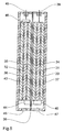
Figur 5 zeigt eine Batterie mit zwei Batteriezellen und entsprechend zwei Elektrodenpaketen, die jeweils in einem Fach eines Gehäuses untergebracht sind.Figure 5 shows a battery with two battery cells and corresponding to two electrode packs, each in one Compartment of a housing are housed.
Jedes Elektrodenpaket weist als Elektroden jeweils eine Katodenplatte 31 bzw. 32 und zwei Anodenplatten 33, 34 bzw. 35, 36 gleicher Größe auf, wobei die Katodenplatten 31 bzw. 32 jeweils mittig zwischen den Anodenplatten 33, 34 bzw. 35, 36 und parallel zu diesen angeordnet sind.Each electrode packet has one as electrodes Cathode plate 31 and 32 and two anode plates 33, 34 and 35, 36 of the same size, the cathode plates 31 and 32 each in the middle between the anode plates 33, 34 and 35, 36 and are arranged parallel to these.
Der Abstand zwischen den Elektrodenplatten 31, 32, 33, 34, 35, 36 liegt in der gleichen Größenordnung wie die Dicke der Elektrodenplatten 31, 32, 33, 34, 35, 36, wodurch zum einen ein gutes Funktionieren der bei der Auf- und Entladung ablaufenden elektrochemischen Prozesse und zum anderen eine optimale Ausnutzung des zur Verfügung stehenden Raums gewährleistet wird.The distance between the electrode plates 31, 32, 33, 34, 35, 36 is of the same order of magnitude as the thickness of the electrode plates 31, 32, 33, 34, 35, 36, whereby to a good functioning of the loading and unloading ongoing electrochemical processes and on the other optimal use of the available space is guaranteed.
Das hier beschriebene Ausführungsbeispiel unterscheidet sich von dem in Figur 4 dargestellten Ausführungsbeispiel durch die Art der Verkapselung und damit zusammenhängend die Art der Montage der Batterie.The embodiment described here differs differs from the embodiment shown in Figure 4 by the type of encapsulation and related the way of mounting the battery.
Das Gehäuse besteht im wesentlichen aus zwei Halbschalen 37 und 43 und einer Trennwand 39.The housing essentially consists of two half-shells 37 and 43 and a partition 39.
Sowohl die Halbschalen 37, 43 als auch die Trennwand 39 bestehen aus einem elektrisch leitfähigen Material und sind elektrisch leitend miteinander verbunden. Die Trennwand 39 bildet eine elektrische Verbindung der beiden Zellen, indem der Anodenverbinder 40 des zweiten Elektrodenpakets und ein an der Katodenplatte 32 des ersten Elektrodenpakets angebrachtes Kontaktstück 44 mittels einer Punktschweißung elektrisch leitend mit der Trennwand 39 verbunden sind, wodurch eine Reihenschaltung der beiden Batteriezellen mit einem Spannungsmittenabgriff entsteht.Both the half-shells 37, 43 and the partition 39 consist of an electrically conductive material and are electrically connected together. The partition 39 forms an electrical connection between the two cells by the anode connector 40 of the second electrode pack and a attached to the cathode plate 32 of the first electrode package Contact piece 44 by means of spot welding are electrically conductively connected to the partition 39, whereby a series connection of the two battery cells with a voltage center tap arises.
Durch die Ausbildung des Gehäuses in Form von zwei Halbschalen 37, 43 ist es vorteilhaft möglich, zunächst die Elektrodenpakete vorzumontieren und auf der Trennwand 39 zu befestigen und anschließend nur noch die Halbschalen 37, 43 an den Umfangsrändern der Trennwand 39 auf diese aufzulegen und abzudichten. Die Durchführung der Schweißarbeiten zur Kontaktierung von Trennwand 39 und Anodenverbinder 40 bzw. Katodenplatte 32 ist deshalb produktionstechnisch einfacher.By designing the housing in the form of two half shells 37, 43, it is advantageously possible to start the Pre-assemble electrode packs and on the partition 39 to fasten and then only the half-shells 37, 43 to be placed on the peripheral edges of the partition 39 and to seal. Implementation of the welding work for Contacting of partition 39 and anode connector 40 or Cathode plate 32 is therefore simpler in terms of production technology.
Ein an der Katodenplatte 31 des zweiten Elektrodenpakets angebrachter Kontakt und der Anodenverbinder 46 des ersten Elektrodenpakets sind elektrisch isoliert und über eine Glasdurchführung 38 bzw. 45 herausgeführt.One on the cathode plate 31 of the second electrode pack attached contact and anode connector 46 of the first Electrode packages are electrically insulated and over one Glass bushings 38 and 45 led out.
In jeder Halbschale 37, 43 befindet sich darüberhinaus jeweils eine verschließbare Öffnung 47, 48 zum Einfüllen des Elektrolyten.In addition, each half-shell 37, 43 is located a closable opening 47, 48 for filling the Electrolytes.
Der Elektrolyt besteht vorzugsweise aus einer Mischung aus Propylencarbonat (PC), Ethylencarbonat (EC), Dimetoxyethan (DME) und LiClO4, aber es sind auch andere bekannte Kombinationen denkbarThe electrolyte preferably consists of a mixture of propylene carbonate (PC), ethylene carbonate (EC), dimetoxyethane (DME) and LiClO 4 , but other known combinations are also conceivable
Die Erfindung beschränkt sich in ihrer Ausführung nicht auf die vorstehend angegebenen bevorzugten Ausführungsbeispiele. Vielmehr ist eine Anzahl von Varianten denkbar, welche von der. dargestellten Lösung auch bei grundsätzlich anders gearteten Ausführungen Gebrauch macht.The invention is not limited in its execution the preferred embodiments given above. Rather, a number of variants are conceivable which of the. shown solution also in principle makes use of different types.
Claims (16)
- A battery-operated implantable medical device, comprising a battery, a measuring device (7) to determine the battery's state of charge by measuring the open circuit voltage and an electrical consumer (6), wherein the battery's open circuit voltage already shows an increased drop in a region in which the remaining energy is still sufficient to maintain operation for a minimum period of time necessary for carrying out a therapeutic process,
characterised in thatthe battery comprises a plurality of cells (1, 2) connected in series,that in order to tap a first potential at the battery's free anode, a first voltage tap (8, 27, 45) is provided, and that in order to tap a second potential at the battery's free cathode (10), a second voltage tap (10, 28, 38) is provided,that the electrical consumer (6) is connected in an electrically-conductive manner to the first and second voltage taps in order to be supplied by the total voltage drop across the battery,that a third voltage tap (3, 9), located at an electrode in the series circuit between the outer electrodes, is provided to tap a reference voltage level and to supply the measuring device (7) with a symmetrical voltage supply,that a measurement circuit (4) is provided, connected in an electrically-conductive manner at its measuring inputs to the first and second voltage taps to determine the total battery voltage, which has a level converter and/or an adder,that the measuring device (7) has a threshold value element (5) for generating a battery status signal, which has at least one threshold value, and is connected at the output of the measurement circuit (4),that the measurement circuit (4) and the threshold value element (5) each have an input for a reference point which is connected in an electrically-conductive manner to the third voltage tap (3, 9), andthat the measurement circuit (4) and the threshold value element (5) are each connected in an electrically-conductive manner to the first and second voltage taps in order to be supplied by a voltage symmetrical to the third voltage tap. - A battery-operated device according to claim 1,
characterised in that the measurement circuit (4) comprises four resistances (R1, R2, R3, R4) and an operational amplifier (OP) with a P input (+), an N input (-), an output (11) and two voltage supply inputs in order to synthesise an adder,that the first resistance (R1) connects the N input (-) of the operational amplifier (OP) with the first voltage tap (8),that the second resistance (R2) connects the N input (-) and the output (11) of the operational amplifier (OP) in order to create a feedback loop,that the third resistance (R3) connects the P input (+) of the operational amplifier (OP) with the third voltage tap (9),that the fourth resistance (R4) connects the P input (+) of the operational amplifier (OP) with the second voltage tap (10),that the voltage supply inputs of the operational amplifier are connected with the first (8) and second (10) voltage taps,and that in order to fulfil the coefficient conditions, the relationship between the resistance values of the second (R2) and the first (R1) resistance, and between the third (R3) and the fourth (R4) resistance is substantially the same. - A battery-operated device according to claim 1,
characterised in that the measurement circuit (4) comprises an amplifier to match its output signal to the threshold value element (5), and has a level converter to allow it to tap the whole voltage range dropped across the battery, and also to interface with the amplifier,that the level converter substantially consists of a Zener diode (DZ) and a first resistance (R3), where the cathode (K) of the Zener diode (DZ) is connected to the first voltage tap (8) and the first resistance (R5) connects the anode (A) of the Zener diode (DZ) with the second voltage tap (10),that a transistor (T) is provided, operating in emitter connection, for tapping the entire voltage range dropped at the battery and for interfacing with the input of an amplifier, where the base (B) is connected to the anode (A) of the Zener diode (DZ) and the emitter (E), is connected to the second voltage tap (10) via a second resistance (R6),that the amplifier substantially consists of a third (R7) , fourth (R8) and fifth (R9) resistance, and an operational amplifier (OP2) with an N input (-), a P input (+) an output and two voltage supply inputs,that the N input (-) of the operational amplifier (OP2) is connected to the collector (C) of the transistor (T) via the third resistance (R7),that the P input (+) of the operational amplifier (OP2) is connected to the third voltage tap (9) via the fourth resistance (R8),that the output of the operational amplifier (OP2) is connected to the N input (-) via the fifth resistance (R9) to create a feedback loop,and that the voltage supply inputs of the operational amplifier (OP2) are connected to the first (8) and second (10) voltage taps. - A battery-operated device according to one of the preceding claims,
characterised in that a casing (26) is provided which is connected in an electrically-conductive manner to the third voltage tap (9). - A battery-operated device according to one of the preceding claims,
characterised in that the measuring device (7) comprises a transmitter/receiver unit for cable-free or cable-transmitted conveyance of the battery status signal to a receiver unit located outside the device and/or for receipt of an activation signal from a transmitter unit located outside the device. - A battery-operated device according to one of the preceding claims,
characterised in that the electrical consumer (6) comprises a control unit for influencing its current consumption, dependent on the state of charge of the battery, and that the battery status signal is present at the input of this control unit. - A battery-operated device according to one of the preceding claims,
characterised in that the battery has a casing (26), which is hermetically-sealed in its assembled state, with two cells which are electrically connected in series by a partition (39) but are spatially separated,that each cell contains an electrode package which has alternating flat or rounded anode plates (16, 17, 18, 19, 20, 21, 22, 23, 33, 34, 35, 36) and cathode plates (12, 13, 31, 32) arranged next to each other,that in each cell the cathode plates (12, 13, 31, 32) are connected in an electrically-conductive manner by a cathode connector (14, 15) and the anode plates (16, 17, 18, 19, 20, 21, 22, 23, 33, 34, 35, 36) are connected in an electrically-conductive manner by an anode connector (24, 25, 40, 46),that the anode connector (25, 40) of the first cell is connected in an electrically-conductive manner to the first voltage tap (27) and the cathode connector (15) of the second cell is connected in an electrically-conductive manner to the second voltage tap (28),and that the anode connector (24) of the second cell and the cathode connector (14) of the first cell are connected to the partition (39), the casing (26) and the third voltage tap (9) in an electrically-conductive manner. - A battery-operated device according to one of the preceding claims,
characterised in that the electrode packages are received in a pouch of synthetic material to insulate them from the casing (26) and the partition (39). - A battery-operated device according to one of the preceding claims,
characterised in that the casing comprises two half-shells (37, 43). - A battery-operated device according to one of the preceding claims,
characterised in that the cathode plates (12, 13, 31, 32) contain a mixture of CrOx, where x is between 2.5 and 2.7, or CrOx and MnO2 with PbCrO4, PbMoO4 or PbO, or a mixture of MnO2 with PbO. - A battery-operated device according to one of the preceding claims,
characterised in that the cathode plates (12, 13, 31, 32) have a coating on their surface which contains a binding agent and a conductive supplement. - A battery-operated device according to one of the preceding claims,
characterised in that the cathode plates (12, 13, 31, 32) have a porosity of between 30 and 50 per cent. - A battery-operated device according to one of the preceding claims,
characterised in that the anode plates (16, 17, 18, 19, 20, 21, 22, 23, 33, 34, 35, 36) substantially consist of lithium. - A battery-operated device according to one of the preceding claims,
characterised in that the battery contains an electrolyte which consists of between 20 and 60 per cent ethylene carbonate (EC) and between 5 and 20 per cent propylene carbonate (PC) and 30 to 70 per cent dimethoxyethane (DME). - A battery-operated device according to one of the preceding claims,
characterised in that the electrolyte contains LiClO4 at a concentration of between 1.0 and 1.5 Mol/l. - A battery-operated device according to one of the preceding claims,
characterised in that the casing (26) substantially consists of CrNi steel, molybdenum, titanium or nickel.
Priority Applications (3)
| Application Number | Priority Date | Filing Date | Title |
|---|---|---|---|
| DE59501575T DE59501575D1 (en) | 1995-11-08 | 1995-11-08 | Battery powered implantable device |
| EP95250273A EP0777286B1 (en) | 1995-11-08 | 1995-11-08 | Implantable battery powered apparatus |
| US08/590,143 US5713936A (en) | 1995-11-08 | 1996-01-23 | Implantable medical device with end-of-life battery detection circuit |
Applications Claiming Priority (1)
| Application Number | Priority Date | Filing Date | Title |
|---|---|---|---|
| EP95250273A EP0777286B1 (en) | 1995-11-08 | 1995-11-08 | Implantable battery powered apparatus |
Publications (2)
| Publication Number | Publication Date |
|---|---|
| EP0777286A1 EP0777286A1 (en) | 1997-06-04 |
| EP0777286B1 true EP0777286B1 (en) | 1998-03-04 |
Family
ID=8221046
Family Applications (1)
| Application Number | Title | Priority Date | Filing Date |
|---|---|---|---|
| EP95250273A Expired - Lifetime EP0777286B1 (en) | 1995-11-08 | 1995-11-08 | Implantable battery powered apparatus |
Country Status (3)
| Country | Link |
|---|---|
| US (1) | US5713936A (en) |
| EP (1) | EP0777286B1 (en) |
| DE (1) | DE59501575D1 (en) |
Families Citing this family (36)
| Publication number | Priority date | Publication date | Assignee | Title |
|---|---|---|---|---|
| EP0872261B1 (en) * | 1997-04-16 | 2004-05-06 | LITRONIK Batterietechnologie GmbH & Co. | Implantable multi-functional medical device |
| CA2297953A1 (en) | 1997-07-25 | 1999-02-04 | Cardiac Pacemakers, Inc. | Battery system for implantable medical device |
| US6167309A (en) * | 1997-09-15 | 2000-12-26 | Cardiac Pacemakers, Inc. | Method for monitoring end of life for battery |
| US6631293B2 (en) * | 1997-09-15 | 2003-10-07 | Cardiac Pacemakers, Inc. | Method for monitoring end of life for battery |
| US6008625A (en) * | 1998-01-16 | 1999-12-28 | Wilson Greatbatch Ltd. | Use of double cells to power an implantable medical device |
| US6552511B1 (en) * | 2000-04-07 | 2003-04-22 | Pacesetter, Inc. | Hybrid battery network for implantable medical device |
| US6584355B2 (en) * | 2001-04-10 | 2003-06-24 | Cardiac Pacemakers, Inc. | System and method for measuring battery current |
| US7151378B2 (en) * | 2001-09-25 | 2006-12-19 | Wilson Greatbatch Technologies, Inc. | Implantable energy management system and method |
| US7239146B2 (en) * | 2003-07-11 | 2007-07-03 | Cardiac Pacemakers, Inc. | Indicator of remaining energy in storage cell of implantable medical device |
| US6940255B2 (en) * | 2003-10-23 | 2005-09-06 | Cardiac Pacemakers, Inc. | Battery charge indicator such as for an implantable medical device |
| US7194308B2 (en) | 2003-11-12 | 2007-03-20 | Cardiac Pacemakers, Inc. | System and method for monitoring or reporting battery status of implantable medical device |
| US7751891B2 (en) * | 2004-07-28 | 2010-07-06 | Cyberonics, Inc. | Power supply monitoring for an implantable device |
| US20060129192A1 (en) * | 2004-11-22 | 2006-06-15 | Wilson Greatbatch | High-energy battery power source for implantable medical use |
| US20060111752A1 (en) * | 2004-11-22 | 2006-05-25 | Wilson Greatbatch | High-energy battery power source for implantable medical use |
| US7769455B2 (en) * | 2006-01-27 | 2010-08-03 | Cyberonics, Inc. | Power supply monitoring for an implantable device |
| US8180462B2 (en) * | 2006-04-18 | 2012-05-15 | Cyberonics, Inc. | Heat dissipation for a lead assembly |
| US20070254212A1 (en) * | 2006-04-28 | 2007-11-01 | Viavattine Joseph J | Battery assembly for use in implantable medical device |
| US8478420B2 (en) * | 2006-07-12 | 2013-07-02 | Cyberonics, Inc. | Implantable medical device charge balance assessment |
| US20080027524A1 (en) * | 2006-07-26 | 2008-01-31 | Maschino Steven E | Multi-electrode assembly for an implantable medical device |
| US8055343B2 (en) * | 2006-10-20 | 2011-11-08 | Cardiac Pacemakers, Inc. | Dynamic battery management in an implantable device |
| US7974707B2 (en) * | 2007-01-26 | 2011-07-05 | Cyberonics, Inc. | Electrode assembly with fibers for a medical device |
| US8868203B2 (en) * | 2007-10-26 | 2014-10-21 | Cyberonics, Inc. | Dynamic lead condition detection for an implantable medical device |
| US8942798B2 (en) * | 2007-10-26 | 2015-01-27 | Cyberonics, Inc. | Alternative operation mode for an implantable medical device based upon lead condition |
| ES2534771T3 (en) * | 2007-12-13 | 2015-04-28 | Cardiac Pacemakers, Inc. | Battery drain detection in an implantable device |
| WO2009127999A1 (en) * | 2008-04-16 | 2009-10-22 | Koninklijke Philips Electronics N.V. | Method and device for predicting a rechargeable battery's lifetime |
| US8868187B2 (en) * | 2008-06-17 | 2014-10-21 | Cardiac Pacemakers, Inc. | Battery depth of discharge in an implantable device |
| US8214042B2 (en) | 2009-05-26 | 2012-07-03 | Boston Scientific Neuromodulation Corporation | Techniques for controlling charging of batteries in an external charger and an implantable medical device |
| FR2950198B1 (en) * | 2009-09-14 | 2011-12-09 | Commissariat Energie Atomique | VOLTAGE CONTROL DEVICE FOR FUEL CELL. |
| US8478428B2 (en) | 2010-04-23 | 2013-07-02 | Cyberonics, Inc. | Helical electrode for nerve stimulation |
| US8874229B2 (en) | 2010-04-28 | 2014-10-28 | Cyberonics, Inc. | Delivering scheduled and unscheduled therapy without detriment to battery life or accuracy of longevity predictions |
| US8577459B2 (en) | 2011-01-28 | 2013-11-05 | Cyberonics, Inc. | System and method for estimating battery capacity |
| US8761884B2 (en) | 2011-04-14 | 2014-06-24 | Cyberonics, Inc. | Device longevity prediction for a device having variable energy consumption |
| US8761885B2 (en) | 2011-04-29 | 2014-06-24 | Cyberonics, Inc. | Battery life estimation based on voltage depletion rate |
| US9002447B2 (en) * | 2013-03-14 | 2015-04-07 | Medtronic, Inc. | Implantable medical device having power supply for generating a regulated power supply |
| EP2846394B1 (en) * | 2013-09-10 | 2016-03-09 | The Swatch Group Research and Development Ltd. | Smart battery provided with a circuit for managing the supply voltage |
| US10639481B2 (en) | 2018-01-08 | 2020-05-05 | Medtronic, Inc. | Power source longevity |
Family Cites Families (11)
| Publication number | Priority date | Publication date | Assignee | Title |
|---|---|---|---|---|
| US3303488A (en) * | 1963-02-11 | 1967-02-07 | Electroscope Res Inc | Electro-optic information display device utilizing an acid-base indicator |
| US3746005A (en) * | 1968-04-11 | 1973-07-17 | American Optical Corp | Constant energy heartbeat stimulating apparatus with pulse width control |
| US3757795A (en) * | 1968-10-28 | 1973-09-11 | Medtronic Inc | Power supply and voltage double output circuitry for implantable electro-medical apparatus |
| US3757793A (en) | 1971-11-15 | 1973-09-11 | Medtronic Inc | Electrochemical cell with stepped voltage output |
| US4424491A (en) * | 1981-05-20 | 1984-01-03 | The United States Of America As Represented By The United States Department Of Energy | Automatic voltage imbalance detector |
| US4445090A (en) * | 1981-08-26 | 1984-04-24 | Towmotor Corporation | Voltage level monitoring and indicating apparatus |
| US4543304A (en) * | 1984-03-19 | 1985-09-24 | Cordis Corporation | Lithium cell having depletion gauge |
| US5045163A (en) * | 1986-02-20 | 1991-09-03 | Raychem Corporation | Electrochemical method for measuring chemical species employing ion exchange material |
| US4839633A (en) * | 1987-06-24 | 1989-06-13 | Texas Instruments Incorporated | Asymmetric voltage monitor for series supplies |
| US5137020A (en) * | 1990-11-29 | 1992-08-11 | Medtronic, Inc. | Battery impedance measurement apparatus |
| US5302902A (en) * | 1991-04-26 | 1994-04-12 | The United States Of America As Represented By The Secretary Of The Army | Abnormal battery cell voltage detection circuitry |
-
1995
- 1995-11-08 DE DE59501575T patent/DE59501575D1/en not_active Expired - Lifetime
- 1995-11-08 EP EP95250273A patent/EP0777286B1/en not_active Expired - Lifetime
-
1996
- 1996-01-23 US US08/590,143 patent/US5713936A/en not_active Expired - Lifetime
Also Published As
| Publication number | Publication date |
|---|---|
| US5713936A (en) | 1998-02-03 |
| DE59501575D1 (en) | 1998-04-09 |
| EP0777286A1 (en) | 1997-06-04 |
Similar Documents
| Publication | Publication Date | Title |
|---|---|---|
| EP0777286B1 (en) | Implantable battery powered apparatus | |
| US10615463B2 (en) | Formation process for lithium-ion batteries with improved tolerace to overdischarge conditions | |
| KR101326118B1 (en) | Method of charging lithium-ion battery | |
| DE69634689T2 (en) | IMPLANTABLE STIMULATOR PROVIDED WITH A RECHARGEABLE, CAPACITIVE ENERGY SOURCE | |
| US6258473B1 (en) | Electrochemical cell having multiplate electrodes with differing discharge rate regions | |
| EP0872908B1 (en) | Electrochemical cell having multiplate and jellyroll electrodes with differing discharge rate regions | |
| US7927742B2 (en) | Negative-limited lithium-ion battery | |
| JP5646715B2 (en) | Lithium-ion battery and medical device | |
| DE102011015792A1 (en) | Lithium ion cell with an array of reference electrodes | |
| EP0984664A1 (en) | Implantable device with a current charging arrangement containing a receiver coil | |
| WO2009021762A1 (en) | Energy storage unit, particularly accumulator | |
| DE602005001042T2 (en) | Implantable active medical device with telemetric RF circuit | |
| JP2008519402A (en) | Lithium-ion battery and medical device | |
| US6677077B2 (en) | Electrochemical cell having multiplate electrodes with differing discharge rate regions | |
| EP3032611B1 (en) | Battery with precisely positioned construction | |
| EP0872261B1 (en) | Implantable multi-functional medical device | |
| DE2850489B2 (en) | Device for monitoring or controlling the operation of rechargeable batteries | |
| DE102013224294A1 (en) | Separator device and battery cell with separator | |
| EP0357952B1 (en) | Rechargeable non-aqueous lithium element with an inorganic electrolyte solution | |
| DE2100011B2 (en) | METHOD AND DEVICE FOR MEASURING AND DISPLAYING THE CHARGE STATE OF NICKEL-CADMIUM ACCUMULATORS | |
| DE10113172A1 (en) | Portable electrical equipment with battery | |
| DE60100606T2 (en) | State-of-charge meter for an alkaline metal battery | |
| US7432001B1 (en) | Prevention of lithium deposition in nonaqueous electrolyte cells by electrolyte-to-cathode weight ratio | |
| DE112022001560T5 (en) | Energy storage device and method for controlling the energy storage device | |
| US20070281207A1 (en) | Prevention of lithium deposition in nonaqueous electrolyte cells by matching device usage to cell capacity |
Legal Events
| Date | Code | Title | Description |
|---|---|---|---|
| GRAG | Despatch of communication of intention to grant |
Free format text: ORIGINAL CODE: EPIDOS AGRA |
|
| PUAI | Public reference made under article 153(3) epc to a published international application that has entered the european phase |
Free format text: ORIGINAL CODE: 0009012 |
|
| GRAH | Despatch of communication of intention to grant a patent |
Free format text: ORIGINAL CODE: EPIDOS IGRA |
|
| 17P | Request for examination filed |
Effective date: 19961217 |
|
| AK | Designated contracting states |
Kind code of ref document: A1 Designated state(s): DE FR GB IT SE |
|
| GRAH | Despatch of communication of intention to grant a patent |
Free format text: ORIGINAL CODE: EPIDOS IGRA |
|
| GRAA | (expected) grant |
Free format text: ORIGINAL CODE: 0009210 |
|
| AK | Designated contracting states |
Kind code of ref document: B1 Designated state(s): DE FR GB IT SE |
|
| REF | Corresponds to: |
Ref document number: 59501575 Country of ref document: DE Date of ref document: 19980409 |
|
| ITF | It: translation for a ep patent filed |
Owner name: BARZANO' E ZANARDO MILANO S.P.A. |
|
| ET | Fr: translation filed | ||
| GBT | Gb: translation of ep patent filed (gb section 77(6)(a)/1977) |
Effective date: 19980608 |
|
| PLBE | No opposition filed within time limit |
Free format text: ORIGINAL CODE: 0009261 |
|
| STAA | Information on the status of an ep patent application or granted ep patent |
Free format text: STATUS: NO OPPOSITION FILED WITHIN TIME LIMIT |
|
| 26N | No opposition filed | ||
| REG | Reference to a national code |
Ref country code: GB Ref legal event code: IF02 |
|
| PGFP | Annual fee paid to national office [announced via postgrant information from national office to epo] |
Ref country code: DE Payment date: 20121109 Year of fee payment: 18 |
|
| PGFP | Annual fee paid to national office [announced via postgrant information from national office to epo] |
Ref country code: IT Payment date: 20121124 Year of fee payment: 18 Ref country code: SE Payment date: 20121122 Year of fee payment: 18 Ref country code: GB Payment date: 20121122 Year of fee payment: 18 |
|
| PGFP | Annual fee paid to national office [announced via postgrant information from national office to epo] |
Ref country code: FR Payment date: 20121217 Year of fee payment: 18 |
|
| REG | Reference to a national code |
Ref country code: SE Ref legal event code: EUG |
|
| GBPC | Gb: european patent ceased through non-payment of renewal fee |
Effective date: 20131108 |
|
| REG | Reference to a national code |
Ref country code: FR Ref legal event code: ST Effective date: 20140731 |
|
| REG | Reference to a national code |
Ref country code: DE Ref legal event code: R119 Ref document number: 59501575 Country of ref document: DE Effective date: 20140603 |
|
| PG25 | Lapsed in a contracting state [announced via postgrant information from national office to epo] |
Ref country code: IT Free format text: LAPSE BECAUSE OF NON-PAYMENT OF DUE FEES Effective date: 20131108 Ref country code: SE Free format text: LAPSE BECAUSE OF NON-PAYMENT OF DUE FEES Effective date: 20131109 Ref country code: DE Free format text: LAPSE BECAUSE OF NON-PAYMENT OF DUE FEES Effective date: 20140603 |
|
| PG25 | Lapsed in a contracting state [announced via postgrant information from national office to epo] |
Ref country code: GB Free format text: LAPSE BECAUSE OF NON-PAYMENT OF DUE FEES Effective date: 20131108 Ref country code: FR Free format text: LAPSE BECAUSE OF NON-PAYMENT OF DUE FEES Effective date: 20131202 |