EP0777053B1 - Scroll fluid machine - Google Patents
Scroll fluid machine Download PDFInfo
- Publication number
- EP0777053B1 EP0777053B1 EP96119235A EP96119235A EP0777053B1 EP 0777053 B1 EP0777053 B1 EP 0777053B1 EP 96119235 A EP96119235 A EP 96119235A EP 96119235 A EP96119235 A EP 96119235A EP 0777053 B1 EP0777053 B1 EP 0777053B1
- Authority
- EP
- European Patent Office
- Prior art keywords
- scroll
- cooling
- gas
- drive shaft
- revolving
- Prior art date
- Legal status (The legal status is an assumption and is not a legal conclusion. Google has not performed a legal analysis and makes no representation as to the accuracy of the status listed.)
- Expired - Lifetime
Links
- 239000012530 fluid Substances 0.000 title claims description 50
- 238000001816 cooling Methods 0.000 claims description 99
- 239000000112 cooling gas Substances 0.000 claims description 22
- 239000002826 coolant Substances 0.000 claims description 4
- 238000003756 stirring Methods 0.000 claims description 3
- 239000007789 gas Substances 0.000 description 97
- 238000004891 communication Methods 0.000 description 17
- 230000002093 peripheral effect Effects 0.000 description 14
- 238000010276 construction Methods 0.000 description 12
- 230000006835 compression Effects 0.000 description 7
- 238000007906 compression Methods 0.000 description 7
- XLYOFNOQVPJJNP-UHFFFAOYSA-N water Substances O XLYOFNOQVPJJNP-UHFFFAOYSA-N 0.000 description 6
- 238000007599 discharging Methods 0.000 description 4
- 230000007246 mechanism Effects 0.000 description 4
- 238000000034 method Methods 0.000 description 4
- 238000012986 modification Methods 0.000 description 4
- 230000004048 modification Effects 0.000 description 4
- 238000009833 condensation Methods 0.000 description 3
- 230000005494 condensation Effects 0.000 description 3
- 239000004519 grease Substances 0.000 description 3
- 230000020169 heat generation Effects 0.000 description 3
- 238000012423 maintenance Methods 0.000 description 3
- 238000002156 mixing Methods 0.000 description 3
- 230000008569 process Effects 0.000 description 3
- 238000012546 transfer Methods 0.000 description 3
- 238000004519 manufacturing process Methods 0.000 description 2
- 230000005855 radiation Effects 0.000 description 2
- 229910000679 solder Inorganic materials 0.000 description 2
- YCKRFDGAMUMZLT-UHFFFAOYSA-N Fluorine atom Chemical compound [F] YCKRFDGAMUMZLT-UHFFFAOYSA-N 0.000 description 1
- 230000006866 deterioration Effects 0.000 description 1
- 238000007865 diluting Methods 0.000 description 1
- 238000001035 drying Methods 0.000 description 1
- 229910052731 fluorine Inorganic materials 0.000 description 1
- 239000011737 fluorine Substances 0.000 description 1
- 239000000463 material Substances 0.000 description 1
- 238000012856 packing Methods 0.000 description 1
- 230000001737 promoting effect Effects 0.000 description 1
- 230000009467 reduction Effects 0.000 description 1
- 239000011347 resin Substances 0.000 description 1
- 229920005989 resin Polymers 0.000 description 1
- 229920006395 saturated elastomer Polymers 0.000 description 1
- 230000008961 swelling Effects 0.000 description 1
Images




Classifications
-
- F—MECHANICAL ENGINEERING; LIGHTING; HEATING; WEAPONS; BLASTING
- F28—HEAT EXCHANGE IN GENERAL
- F28D—HEAT-EXCHANGE APPARATUS, NOT PROVIDED FOR IN ANOTHER SUBCLASS, IN WHICH THE HEAT-EXCHANGE MEDIA DO NOT COME INTO DIRECT CONTACT
- F28D15/00—Heat-exchange apparatus with the intermediate heat-transfer medium in closed tubes passing into or through the conduit walls ; Heat-exchange apparatus employing intermediate heat-transfer medium or bodies
- F28D15/02—Heat-exchange apparatus with the intermediate heat-transfer medium in closed tubes passing into or through the conduit walls ; Heat-exchange apparatus employing intermediate heat-transfer medium or bodies in which the medium condenses and evaporates, e.g. heat pipes
-
- F—MECHANICAL ENGINEERING; LIGHTING; HEATING; WEAPONS; BLASTING
- F04—POSITIVE - DISPLACEMENT MACHINES FOR LIQUIDS; PUMPS FOR LIQUIDS OR ELASTIC FLUIDS
- F04C—ROTARY-PISTON, OR OSCILLATING-PISTON, POSITIVE-DISPLACEMENT MACHINES FOR LIQUIDS; ROTARY-PISTON, OR OSCILLATING-PISTON, POSITIVE-DISPLACEMENT PUMPS
- F04C29/00—Component parts, details or accessories of pumps or pumping installations, not provided for in groups F04C18/00 - F04C28/00
- F04C29/04—Heating; Cooling; Heat insulation
-
- F—MECHANICAL ENGINEERING; LIGHTING; HEATING; WEAPONS; BLASTING
- F04—POSITIVE - DISPLACEMENT MACHINES FOR LIQUIDS; PUMPS FOR LIQUIDS OR ELASTIC FLUIDS
- F04C—ROTARY-PISTON, OR OSCILLATING-PISTON, POSITIVE-DISPLACEMENT MACHINES FOR LIQUIDS; ROTARY-PISTON, OR OSCILLATING-PISTON, POSITIVE-DISPLACEMENT PUMPS
- F04C18/00—Rotary-piston pumps specially adapted for elastic fluids
- F04C18/02—Rotary-piston pumps specially adapted for elastic fluids of arcuate-engagement type, i.e. with circular translatory movement of co-operating members, each member having the same number of teeth or tooth-equivalents
- F04C18/0207—Rotary-piston pumps specially adapted for elastic fluids of arcuate-engagement type, i.e. with circular translatory movement of co-operating members, each member having the same number of teeth or tooth-equivalents both members having co-operating elements in spiral form
- F04C18/0215—Rotary-piston pumps specially adapted for elastic fluids of arcuate-engagement type, i.e. with circular translatory movement of co-operating members, each member having the same number of teeth or tooth-equivalents both members having co-operating elements in spiral form where only one member is moving
- F04C18/0223—Rotary-piston pumps specially adapted for elastic fluids of arcuate-engagement type, i.e. with circular translatory movement of co-operating members, each member having the same number of teeth or tooth-equivalents both members having co-operating elements in spiral form where only one member is moving with symmetrical double wraps
Definitions
- This invention relates to scroll fluid machine, in which sucked fluid is compressed with stationary and revolving scrolls and discharged to the outside.
- a scroll fluid machine compresses fluid sucked from its peripheral part in a sealed space formed by its stationary and revolving scrolls progressively as the fluid is fed toward its central part, and discharges the compressed fluid from the central part.
- the temperature in the sealed space formed by the laps is elevated. This poses a problem that bearings, seal members, etc. provided in drive parts are soon deteriorated.
- the scrolls are cooled to hold the temperature within a predetermined temperature.
- Well-known cooling systems cool either non-driven part, i.e., the stationary scroll, or driven part, i.e., the revolving scroll.
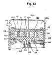
- Fig. 13 shows a technique concerning a non-driven part cooling system.
- a revolving scroll 116 which is mounted on a frame 109 provided in a sealed housing 105, comprises a disc-like body 114 having a shaft 113 depending therefrom.
- the frame 109 has a central hole, in which a drive shaft 104 coupled to a drive (not shown) is fitted for rotation, and the shaft 113 is eccentrically coupled to the drive shaft 104.
- the revolving scroll 116 has a lap 115 engaging with a lap 111 of a stationary scroll 112.
- the stationary scroll 112 has a peripheral wall having a suction hole 118.
- a sealed space formed by the laps 111 and 115 is progressively reduced in volume, thus compressing gas entering the sealed space.
- the compressed gas is discharged from a discharge hole 121 formed in a central part of the stationary scroll 112 through a discharge pipe 120 to the outside.
- a plurality of radially spaced-apart heat pipes 122 are provided in the body 110 of the stationary scroll 112 to remove heat generated in a compression stroke as described above.
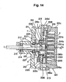
- Fig. 14 shows a well-known cooling system for cooling driven part, i.e., the revolving scroll.
- a housing 211 as shown comprises a rear and a front housing part 212 and 213, and a drive shaft 214 is supported for rotation by bearings 215 in a bearing portion of the rear housing part 212.
- the drive shaft 214 has an extension projecting outward from the bearing portion and coupled to a motor (not shown).
- the drive shaft 214 also has an eccentric portion 214b, which has an eccentric axis O2-O2 with respect to the axis O1-O1 of the drive shaft 214 by a distance ⁇ .
- a revolving scroll 216 which is coupled to the eccentric portion 214b of the drive shaft 214, has a disc-like plate 216a having a mirror finished front surface, a spiral lap 216b formed on the front side of the mirror finished plate 216a, a boss 216c formed as the driving center with an axial line 02-02 on the rear side of the plate 216a and having smaller diameter than the inner peripheral surface edge of above portion 213b, a ring-like ridge 216d formed on the rear side of the above 216a and on the periphery thereof, and a plurality of radial vent hole 216e formed in a diameter direction of above 216d.
- a stationary scroll 221 which is secured to the front housing part 213, has a disc-like plate 211a having a mirror finished rear surface, a spiral lap 221b formed on the rear side of the plate 211a and a peripheral wall 221c surrounding the lap 221b.
- the laps 216b and 221b of the revolving and stationary scrolls 216 and 221 engage with or lap each other at a predetermined deviation angle, and they form a plurality of compression chambers or spaces when the revolving scroll 216 is revolved.
- the drive shaft 214 has a counterweight 225 mounted on its portion extending in the rear housing part 212, and a centrifugal fan 226 is mounted on the counterweight 225 to generate cooling air flow with the rotation of the drive shaft 214.
- the heat radiating portions of the heat pipes 122 are cooled by their heat radiation to the sealed housing inner space 105a, which is filled with gas sucked through a suction pipe 119.
- the suction hole 118 In communication with the space 105a is the suction hole 118, through which gas enters the compression space which is formed by the stationary and revolving scrolls. This means that gas having been elevated in temperature by the heat radiation from the heat pipes 122 again enters the compression space through the suction hole 118, thus reducing the cooling efficiency.
- JP-A-61-200391 from which the pre-characterising part of claim 1 starts out discloses a scroll fluid machine having a drive shaft for driving a revolving scroll in meshing engagement with a stationary scroll.
- the drive shaft has a longitudinal cooling passage open at only one end, and a narrow feeding pipe is introduced from the open end into the cooling passage to inject a fluid into the same and let it return in the space between the walls of the feeding pipe and of the cooling passage to be discharged again from the open end of the cooling passage.
- This prior art has the disadvantage that the forward and backward flow of the fluid results in a relatively high flow resistance, the diameter of the cooling passage must be large and the fluid must be forced through the cooling passage.
- JP-A-59-155593 discloses a motor having a shaft provided with a cooling passage.
- US 5,417,554 relates to a scroll compressor having a cooling fan and cooling fins on the stationary and orbiting scroll bodies.
- An embodiment of the invention provides a scroll fluid machine with improved durability.
- a further embodiment of the invention provides a scroll fluid machine which is rediced in size.
- a scroll fluid machine comprising stationary scrolls each having a lap embedded spirally in a scroll body such as to extend from a central part toward the outer periphery of the scroll body, and a revolving scroll having spiral laps embedded in a scroll body and engaging with the spiral laps of the stationary scrolls, said the revolving scroll being coupled to a drive shaft coupled to a drive, cooling means is provided in the drive shaft.
- the drive shaft can be cooled directly. Since the revolving scroll is driven by the drive shaft coupled to the drive, it is possible to cool heat generated in a process, in which fluid sucked from the edge of the scroll is led to a central part thereof while being progressively compressed. It is thus possible to obtain efficient cooling of bearings and seal members provided around the revolving scroll and also those provided around the drive shaft.
- the drive shaft is formed with a hollow cooling passage for introducing cooling gas from one end and discharging the same from the other end in it.
- turbulent flow forming means is provided in the cooling passage to stir the introduced cooling gas.
- gas cooling means with a simple construction. Besides, by providing the turbulent flow forming means the gas temperature difference between an edge part of the cooling passage adjacent the surface thereof and a central part thereof can be quickly reduced, thus obtaining an improved cooling efficiency.
- a fan is provided at one end of the drive shaft while providing at the other end of the cooling passage with radial communication holes toward the outer periphery of the above drive shaft, thus causing gas having contributed to the cooling by the fun to be compulsively exhausted through the communication holes to cool the drive shaft.
- the revolving scroll 3 (Fig. 3) is cooled by cooling gas 32 passing through the cooling passage 11Ad (Fig. 1) or 11Bd (Fig. 2), and the gas that has contributed to the cooling is exhausted by the fan 13 through the communication holes 11Ac (Fig. 1) or 11Bc (Fig. 2).
- the drive shaft prefferably formed to be hollow and provide heat transfer means therein.
- a scroll fluid machine comprising stationary scrolls having a lap embedded spirally in a scroll body such as to extend from a central part toward the outer periphery of the scroll body, and a revolving scroll having spiral laps embedded in a scroll body and engaging the spiral laps of the stationary scrolls, said the revolving scroll being coupled to a drive shaft (coupled to a drive) at the central portion of the scroll body, the eccentric portion of the drive shaft being cooled.
- the revolving scroll thus has a central part of its body driven by the drive shaft coupled to the drive, and heat generated in the process, in which fluid sucked from the edge of the scroll is led to a central part thereof while being progressively compressed, can be removed in the central part which is at the highest temperature.
- parts provided in the neighborhood of the central part of the revolving scroll can be cooled efficiently.
- the central part of the revolving scroll 3 (Fig., 3) is cooled by cooling gas 32 passing through the cooling passage 11Ad (Fig. 1) or 11Bd (Fig. 2), and the gas having contributed to the cooling is compulsively exhausted by the fan 13 through the communication holes 11Ac (Fig. 1) or 11Bc (Fig. 2).
- the fan 13 further exhausts gas that has cooled the rear side of the housing part 4 (Fig. 3), i.e., the stationary scroll, with the lap 7 embedded therein, in the directions of arrows 40 in Fig. 6.
- heat transfer means being able to cool a central part of said revolving scroll, said fan being able to cool said revolving scroll inclusive of the heat radiating zones of the heat transfer means or said stationary scrolls on the side thereof opposite the laps side.
- the fans (Fig. 3) produce cooling air flows in the directions of arrows 35 and 36 to cool the heat radiating zones (i.e., condensing zones).
- the fans 12 and 13 produce cooling air flows in the directions of arrows 39 and 40 (Fig. 6) to cool the heat pipes, while exhausting gas having cooled the stationary scrolls constituted by the housing parts 4 and 5 on the side thereof opposite the laps.
- the invention is further applicable to scroll fluid machine comprising a single-lap revolving scroll with a single lap embedded in one side surface of the scroll body and a single stationary scroll.
- either the stationary scroll or the revolving scroll may be located near a fan for exhausting gas having cooled the heat pipes and the stationary or revolving scroll on the side thereof opposite the lap.
- Fig. 3 shows a pump 1 having a shaft 11, which is coupled at its right end to a drive shaft of a motor 2 for being rotated by the torque thereof.
- the shaft 11 has a central eccentric portion 11a having some swelling part to rotating central axial line of outer peripheral, which the both edge side of a eccentric portion 11a are driven to be supported for rotation in bearings and packing sections in housing parts 4 and 5.
- the housing parts 4 and 5 are cap-like in shape and constitute respective stationary scrolls. Their peripheral walls are sealed together via an intervening seal member to define a sealed inner space.
- the housing part 4 has a lap sliding surface 4b perpendicular to its axis and also has a hole 4i (see Fig. 6), which is formed in a central portion of the lap sliding surface 4b, and in which the end portion of the shaft 11, adjacent the eccentric portion 11a and not eccentric, is fitted for rotation.
- the housing part 4 has a lap 7 embedded in it.
- the lap 7 (see Figs 7(a) and 7(b)) is spiral clockwise when viewed in the direction of arrow 30 and has an end 7a located in the neighborhood of the hole 4i.
- the lap 7 has a tip groove formed in its tip or outer edge.
- a tip seal 14 is fitted in the tip groove.
- the tip seal 14 is made of a fluorine type resin or the like and is self-lubricating to provide perfect seal with the associated rubbing surface in contact with it (see Fig. 6).
- the housing part 4 further has a discharge hole 4c (see Figs. 6, 7), which is open in the lap rubbing surface 4b in the neighborhood of the end 7a of the lap 7. Compressed gas is discharged through the discharge hole 4c through a discharge passage 4d from a discharge port 9 formed in the peripheral wall 4a of the housing part 4 to the outside.
- the side of the housing part 4 opposite the lap 7 constitutes a scroll body 4f which is provided with a suction pipe 10 for gas ballast gas introduction. Gas is sucked from the suction pipe 10 through a suction passage 4g (see Fig. 6) and suction hole 4e into a sealed space R.
- Three revolving mechanism sets 17 are mounted on the peripheral wall 4a of the housing part 4 on 3 spots by 120° in the peripheral direction.
- revolving mechanism sets 17 are coupled to a revolving scroll to be described later.
- a peripheral port 4a of housing 4 has a absorbing port 8 which are coupled to a vessel to be evacuated (not shown), at where the gas is sucked through the hole 8a from above vessel.
- the other housing part 5 likewise has a lap sliding surface 5b perpendicular to its axis, as well as a hole formed in a central portion of the lap sliding surface 5b, the end portion of the shaft 11 adjacent the eccentric portion 11a and not eccentric being fitted for rotation in the hole.
- a lap 6 which is spiral counterclockwise when viewed in the direction of arrow 31, is also embedded in the housing part 5, and has an end located in the neighborhood of the hole.
- the lap 6 has a tip groove formed on its tip, and a tip seal 14 (Fig. 6) is fitted in the tip groove and provides perfect seal with the associated rubbing surface in contact with it.
- a revolving scroll 3 is disposed for revolving in the inner space defined in the housing parts 4 and 5.
- the revolving scroll 3 is disc-like in shape and has opposite side lap rubbing surfaces 3d and 3f with laps 26 and 27 embedded thereon for engaging with the stationary scroll laps.
- the lap 26 is spiral clockwise when viewed in the direction of arrow 30, and the opposite side lap 27 is spiral counterclockwise when viewed in the direction of arrow 31.
- the revolving scroll 3 has a central hole 3a, in which the eccentric portion 11a of the shaft 11 is fitted for rotation.
- the central hole 3a is surrounded by ring-like lap ends 26a and 27a of the laps 26 and 27 over the entire length of the eccentric portion 11a.
- the lap ends 26a and 26b communicate with a passage 3b leading to the discharge hole 4c, and a final compression space defined by the laps 26 and 6 is communicated by a hole 3g with the passage 3b.
- Fan 12 and 13 are provided outside of housing 5 and housing 4 on the shaft 11 to cool the vacuum pump and a cover 18 and 19 having a hole 18a in the central portion are mounted in housing 5 and 4 in order to protect those fans.
- a shield 29B (see Fig. 5) having numbers of holes 29Ba and 29Bb
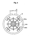
- a shield 29A (see Fig. 4) having numbers of holes 29Aa and 29Ab.
- the three revolving mechanism sets 17 on 3 spots by 120° in the peripheral direction are supported at one end by housing 4 and at the other end by outer periphery of the revolving scroll, and the revolving scrolls are revolved through above revolving mechanism 17 by an axis eccentric rotating centers with respect to the stationary scrolls.
- Figs. 7(a) to 10(a) are taken along line A-A in Fig. 6, and Figs. 7(b) to 10(b) are taken along line B-B.
- the revolving scroll 3 is revolved to suck gas from a vessel (not shown).
- the sucked gas is led from the outer peripheries of the stationary scroll laps by the revolving scroll laps 26 and 27 into a sealed space defined by these stationary and revolving scroll laps for compression in the space.
- the sealed space is changed from one shown at R0 in Fig., 10(a) to one shown at R1 in Fig. 7(a), whereupon the suction hole 4e of the gas ballast suction pipe 10 is opened.
- the pressure of the compressed fluid in the sealed spaces R3 and L3 at this moment is higher than the gas ballast gas pressure.
- the stationary scroll suction hole 4e is small in diameter while the revolving scroll is driven at a high speed and gas ballast gas is present in the suction hole, only slight compressed gas flows reversely through the suction hole 4e.
- the suction hole 4e is closed by the lap end 27a of the revolving scroll 3 right before the sealed spaces R4 and L4 (Figs. 10) are communicated with the discharge hole 4c.
- the scroll fluid machine operating as described above, continuously compresses fluid sucked from its periphery as the fluid is led toward its central part. That is, the fluid is compressed utmost in the central part, which is thus elevated to the highest temperature.
- Cooling means for cooling the central part of the apparatus will now be described.
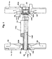
- Fig. 1 shows cooling means, i.e., a shaft/fan assembly, in a first embodiment of the scroll fluid machine according to the invention.
- a drive shaft 11A has a cooling passage 11Ad formed in it along its axis of rotation for introducing outer gas from a left open end 11Ag.
- the right end of the cooling passage 11Ad is shielded by a shield 23.
- the drive shaft 11A has a plurality of radially spaced-apart holes 11Ac formed adjacent its right end 11Ab and communicating the cooling passage 11Ad and its outside.
- a fan 13 is provided on the drive shaft 11A, that is, its boss 20A is fitted on and secured to the right end 11Ab of the drive shaft 11A.
- the boss 20A has holes 13a in communication with the holes 11Ac. The fan 13 thus can exhaust cooling gas having cooled the cooling passage 11Ad through the holes 13a to the outside as shown by arrows 34.
- Another fan 12 is provided on the left end llAe of the drive shaft 11A with its boss 20B secured thereto by a nut 22 screwed on a threaded end portion 11Af of the drive shaft 11A.
- the fan 12 can exhaust cooling gas, which has been led through holes 29Ba in a shield 29B (Fig. 5) and cooled the housing part 5 (Fig. 3) on the side thereof opposite the lap, to the outside as shown by arrows 39.
- Fig. 2 is a view showing a shaft/fan assembly in a second embodiment of the scroll fluid machine according to the invention.
- a drive shaft 11B has a cooling passage 11Bd formed in it along its axis of rotation for introducing external gas from a left open end 11Bg.
- a helical groove 11Bb is formed in the inner surface of the passage 11Bd.
- the right end of the passage 11Bd is shielded by a shielded 23.
- the drive shaft 11B has a plurality of radially spaced-apart holes 11Bc formed adjacent its right end 11Bb and communicating the cooling passage 11Bd and its outside.
- a fan 13 is provided on the drive shaft 11 on the drive shaft 11B with its boss 20A fitted on and secured to the right end 11Bb of the drive shaft 11B, the boss 20A having a plurality of radially spaced-apart holes 13a. Coolant having cooled the cooling passage 11Bd is by the fan 13 through the holes 13a exhausted to the outside as shown by arrows 34.
- Another fan 12 is provided on the left end 11Be of the drive shaft 11B with its boss 20B secured thereto by a nut 22 screwed on a threaded end portion 11Bf of the drive shaft 11B.
- the fan 12 exhausts cooling gas having cooled the housing part (Fig. 3) on the side thereof opposite the lap through holes 29Ba formed in a shield 29B (Fig. 5) to the outside as shown by arrows 39.
- a central part of the revolving scroll 3 is cooled by cooling gas 32 passing through the cooling passage 11Bd.
- the helical groove 11Bh functions as turbulent flow forming means to stir the introduced cooling gas, thus quickly reducing the gas temperature difference between an edge part of the cooling passage adjacent the surface thereof and a central part of the passage.
- efficient cooling can be obtained.
- the gas having cooled the housing parts 4 and 5 on the side thereof opposite the stationary scroll laps is exhausted through the holes 29Aa and 29Ba in the shields 29A and 29B (Figs. 4 and 5) and together with gas having cooled the central part of the revolving scroll 3 to the outside as shown by arrows 39 and 40 (Fig. 6).
- Fig. 11 is a view showing a modification of the shaft/fan assembly in the first embodiment of the scroll fluid machine of Fig. 1 according to the invention.
- a drive shaft 11D into which cooling gas is introduced comprises a small diameter cylindrical part 11Dk, a large diameter eccentric cylindrical part 11Da, and a medium diameter cylindrical part 11Db.
- the small and medium diameter parts 11Dk and 11Db each have a cooling passage 11Dd of an equal diameter
- the large diameter eccentric part 11Da has a cooling passage 11Dj of a greater diameter and is provided between two cooling passages 11Dd of left and right side.
- solders 4 cones having 40a, 40b, 40c and 40d provided between adjacent ends of them.
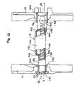
- Fig. 12 is a view showing a modification of the shaft/fan assembly in the second embodiment of the scroll fluid machine according to the invention.
- a drive shaft 11E into which cooling gas is introduced comprises a small diameter cylindrical part 11Ek, a large diameter eccentric cylindrical part 11Ea, and a medium diameter cylindrical part 11Eb, these parts 11Ek, 11Ea and 11Eb being interconnected along line N-N by solders 40a to 40d provided between adjacent ends of them.
- the small and medium diameter parts 11Ek and 11Eb each have a cooling passage 11Ed of an equal diameter, and the large diameter eccentric part 11Ea has a passage 11Ej of a greater diameter.
- a helical groove 11Eh is formed in the inner surfaces of the passages 11Ed.
- this turbulent flow forming means As described before in connection with the second embodiment, it is possible to replace this turbulent flow forming means with a helical coil spring inserted in the passages 11Ed and 11Ej.
- a mixing pipe having an outer diameter equal to the inner diameter of the cooling passages 11Ed for mixing two different fluids may be inserted in the passages 11Ed.
- the invention has so far been described in conjunction with embodiments comprising the double-side revolving scroll with laps embedded in the opposite side surfaces of the scroll body and the stationary scrolls as shown in Fig. 3.
- this is by no means limitative, and the invention is also applicable to an embodiment comprising a single lap revolving scroll with a single lap embedded in only one side surface of a scroll body and a single stationary scroll.
- either the stationary scroll or the revolving scroll is located near the fan noted above.
- the fan can of course exhaust gas having cooled the heat pipes and also the stationary or revolving scroll on the side thereof opposite the lap.
- the fan is provided at one end of the drive shaft, which has the radial communication holes formed adjacent the other end of the cooling passage for communication thereof toward the outer periphery of axis.
- the fan serves to compulsively exhaust gas having contributed to the cooling of the cooling passage through the communication holes, thus cooling the revolving scroll central part while also cooling other parts of the scroll fluid machine with gas not passing through the cooling passage.
- the central part of the revolving scroll 3 is cooled by cooling gas 32 passing through the cooling passage 11Ad (Fig. 1) or 11Bd (Fig. 2), while the gas having contributed to the cooling is compulsively exhausted by the fan 13 through the communication holes 11Ac (Fig. 1) or 11Bc (Fig. 2).
- the fan 13 further exhausts gas having cooled the rear side of the housing part 4 as the stationary scroll opposite the lap side thereof as shown by arrows 40 (Fig.6).
- the scroll fluid machine drive shaft on which the central part of the revolving scroll is mounted, and which is coupled to the drive, can be cooled directly, that is, heat generated in the process, in which fluid sucked from the edge of the revolving scroll is fed to the central part thereof while being progressively compressed, can be removed at the central part which is elevated to the highest temperature. It is thus possible to efficiently cool bearings and seal members provided near the revolving scroll central part and the drive shaft.
- the thermal expansion difference between the stationary and revolving scrolls can be eliminated to provide a uniform temperature distribution, prevent scoring of the laps and extend the grease maintenance cycle, thus improving the durability.
- the lap sliding surface of the revolving scroll is formed with the gas ballast suction hole, which has a smaller diameter than the thickness of the revolving scroll laps so that it can be opened and closed by driving of above revolving scroll lap, that is, closed above suction hole in synchronism to the instant when the final sealed spaces formed by the stationary and revolving scrolls are communicated with the discharge passage to the outside. More specifically, the gas ballast suction hole is closed while the final sealed spaces are communicated with the discharge passage. Thus, compressed fluid can be discharged through the discharge passage to the outside without possibility of its back flow through the suction hole.
- the gas ballast suction hole is formed in one of the stationary scrolls
- the communication hole is formed in the scroll body of the revolving scroll to lead gas to the sealed space formed by the lap of the other stationary scroll and the associated revolving scroll lap
- the discharge hole is formed in the afore-mentioned one stationary scroll, thereby discharging compressed gas from both the sealed spaces through the discharge hole to the outside. That is, the suction hole and the discharge hole are both formed in one of the stationary scrolls.
- those above two holes are concentratedly provided on the side of the afore-mentioned one stationary scroll opposite the lap side thereof. This construction is simple and ready to manufacture compared to the case of forming the holes distributedly in the two stationary scrolls.
- both the stationary scroll each need not be formed with a gas ballast suction hole but only a single stationary scroll may be formed with a suction hole, thus simplifying the construction and manufacture.
- the suction pipe 10 and the discharge passage 4c, 4d are may be provided on the side of the hosing part 5 instead of providing them on the side of the housing part 4 (Fig. 6).
- ballast gas suction holes in both the housing parts 4 and 5 to introduce gas ballast gas into the spaces R and L formed by the revolving and stationary scrolls from both sides.
- gas ballast gas it is not necessary to arrange a suction hole 3e which are connected the space R with L, thus gas ballast gas can be introduced quickly from both sides, and the cooling efficiency is improved.
- atmospheric gas may be introduced through the suction pipe 10. It is desirable to heat dry gas air, N 2 gas, etc. to be introduced. In this case, it is possible to quicken the drying of vapor or fluid in the scroll lap and prevent it from deterioration.
- cooing means having high cooling efficiency is used to prevent scoring of the laps and extend the grease maintenance cycle for providing improved durability.
- the clearance between adjacent scrolls can be reduced. Furthermore, the high speed operation can be increased to increase the attainable pressure.
Landscapes
- Engineering & Computer Science (AREA)
- Mechanical Engineering (AREA)
- General Engineering & Computer Science (AREA)
- Life Sciences & Earth Sciences (AREA)
- Sustainable Development (AREA)
- Physics & Mathematics (AREA)
- Thermal Sciences (AREA)
- Rotary Pumps (AREA)
- Applications Or Details Of Rotary Compressors (AREA)
Description
Claims (7)
- A scroll fluid machine, comprising:characterised in thata stationary scroll (4, 5) with an embedded spiral lap (6, 7) extending from a central part of a scroll body toward the outer periphery edge thereof,a revolving scroll (3) with an embedded spiral lap (26, 27) engaging said stationary scroll spiral lap, said revolving scroll having a scroll body coupled to a drive shaft (11) coupled to a drive (2),said drive shaft (11) for driving said revolving scroll (3) having a hollow longitudinal cooling passage (11Ad to 11Ed), one end of the cooling passage having an inlet opening (11Ag to 11Eg) for a coolant flowing therethrough,
the other end of the cooling passage communicates with radial holes (11Ac to 11Ec) in the drive shaft (11) for radially outwardly exhausting the coolant flowing through the cooling passage. - A machine according to claim 1, wherein a fan (13) is provided on the drive shaft (11) near said radial holes (11Ac to 11Ec) to let cooling gas compulsively flow through the cooling passage (11Ad to 11Ed) and outwardly through said radial holes.
- A machine according to claim 1 or 2, wherein turbulent flow forming means (11Bh, 11Eh) is provided in the cooling passage (11Ad to 11Ed) to stir the coolant flowing therethrough.
- A machine according to any of claims 1 to 3, wherein said revolving scroll (3) is coupled to an eccentric portion (11Aa to 11Ea) of the drive shaft (11) for being driven to revolve when the drive shaft rotates.
- A machine according to any of claims 1 to 4, comprising another stationary scroll (5, 4) with a spiral lap (7, 6),
wherein said revolving scroll (3) has a disk-like body, said spiral lap (26, 27) of the revolving scroll being provided on one side (3d, 3f) of the body, another spiral lap (27, 26) being provided on the other side (3f, 3d) of the body and engaging the spiral lap of the other stationary scroll. - A machine according to claim 2, wherein said fan (13) is provided to compulsively exhaust cooling gas not having flown through the cooling passage for cooling a non-central part of the revolving scroll (3) and to compulsively exhaust cooling gas flowing through the cooling passage and the radial holes for cooling a central part of the revolving scroll.
- A machine according to claim 2, wherein said fan (13) is provided to compulsively exhaust cooling gas not having passed through said cooling passage for cooling said stationary scroll (26, 27) and to compulsively exhaust cooling gas flowing through the cooling passage and the radial holes for cooling the revolving scroll (3).
Priority Applications (1)
| Application Number | Priority Date | Filing Date | Title |
|---|---|---|---|
| EP01114907A EP1146232B1 (en) | 1995-11-30 | 1996-11-29 | Scroll fluid machine |
Applications Claiming Priority (3)
| Application Number | Priority Date | Filing Date | Title |
|---|---|---|---|
| JP334342/95 | 1995-11-30 | ||
| JP33434295A JP3423514B2 (en) | 1995-11-30 | 1995-11-30 | Scroll fluid machine |
| JP33434295 | 1995-11-30 |
Related Child Applications (1)
| Application Number | Title | Priority Date | Filing Date |
|---|---|---|---|
| EP01114907.7 Division-Into | 2001-06-19 |
Publications (2)
| Publication Number | Publication Date |
|---|---|
| EP0777053A1 EP0777053A1 (en) | 1997-06-04 |
| EP0777053B1 true EP0777053B1 (en) | 2003-04-16 |
Family
ID=18276297
Family Applications (2)
| Application Number | Title | Priority Date | Filing Date |
|---|---|---|---|
| EP01114907A Expired - Lifetime EP1146232B1 (en) | 1995-11-30 | 1996-11-29 | Scroll fluid machine |
| EP96119235A Expired - Lifetime EP0777053B1 (en) | 1995-11-30 | 1996-11-29 | Scroll fluid machine |
Family Applications Before (1)
| Application Number | Title | Priority Date | Filing Date |
|---|---|---|---|
| EP01114907A Expired - Lifetime EP1146232B1 (en) | 1995-11-30 | 1996-11-29 | Scroll fluid machine |
Country Status (4)
| Country | Link |
|---|---|
| US (3) | US5842843A (en) |
| EP (2) | EP1146232B1 (en) |
| JP (1) | JP3423514B2 (en) |
| DE (2) | DE69631447T2 (en) |
Cited By (1)
| Publication number | Priority date | Publication date | Assignee | Title |
|---|---|---|---|---|
| CN108561218A (en) * | 2017-12-29 | 2018-09-21 | 宁国东方碾磨材料股份有限公司 | A kind of marine ship engine combination cooling structure |
Families Citing this family (71)
| Publication number | Priority date | Publication date | Assignee | Title |
|---|---|---|---|---|
| EP0798463A3 (en) * | 1996-03-29 | 1998-02-25 | Anest Iwata Corporation | Oil-free scroll vacuum pump |
| JP3478940B2 (en) * | 1997-03-04 | 2003-12-15 | 株式会社日立産機システム | Scroll compressor |
| JP3985051B2 (en) * | 1997-07-28 | 2007-10-03 | 独立行政法人 日本原子力研究開発機構 | Double wrap dry scroll vacuum pump |
| JPH1182333A (en) * | 1997-09-12 | 1999-03-26 | Kimie Nakamura | Scroll fluid machine |
| JP2001516848A (en) * | 1997-09-16 | 2001-10-02 | アテリエ ビスク ソシエテ アノニム | Spiral vacuum pump |
| US6511308B2 (en) * | 1998-09-28 | 2003-01-28 | Air Squared, Inc. | Scroll vacuum pump with improved performance |
| US6394777B2 (en) * | 2000-01-07 | 2002-05-28 | The Nash Engineering Company | Cooling gas in a rotary screw type pump |
| TW427449U (en) * | 2000-01-28 | 2001-03-21 | Ind Tech Res Inst | Cooling device for hollow screw |
| DE10031143A1 (en) * | 2000-06-27 | 2002-01-17 | Knorr Bremse Systeme | Bearings for spiral rotary compressor with cooling air ducted over the bearings for long life operation |
| JP3771561B2 (en) * | 2002-02-15 | 2006-04-26 | コリア・インスティテュート・オブ・マシナリー・アンド・マテリアルズ | Scroll expander having heating structure, and scroll-type heat exchange system using the same |
| EP1483822A1 (en) * | 2002-03-14 | 2004-12-08 | Siemens Aktiengesellschaft | Superconducting device with a cold head of a refrigeration unit with a thermosyphon effect thermally coupled to a rotating superconducting winding |
| DE10221639B4 (en) * | 2002-05-15 | 2004-06-03 | Siemens Ag | Establishment of superconductivity technology with a superconducting magnet and a cooling unit |
| US7121817B2 (en) * | 2002-05-30 | 2006-10-17 | Anest Iwata Corporation | Scroll fluid machine comprising compressing and expanding sections |
| JP2003343203A (en) * | 2002-05-30 | 2003-12-03 | Anest Iwata Corp | Scroll type fluid machine provided with compression and expansion parts |
| US20040070152A1 (en) * | 2002-08-05 | 2004-04-15 | Oehman Robert E. | Ventilated pump shaft seal |
| JP4373130B2 (en) | 2003-05-23 | 2009-11-25 | アネスト岩田株式会社 | Scroll fluid machinery |
| US7309219B2 (en) * | 2003-12-26 | 2007-12-18 | Hitachi, Ltd. | Scroll type fluid machinery |
| RU2287720C2 (en) * | 2004-05-12 | 2006-11-20 | Закрытое акционерное общество "Научно-исследовательский институт центробежных и роторных компрессоров им. В.Б. Шнеппа" | Spiral machine |
| US6953330B1 (en) * | 2004-08-02 | 2005-10-11 | Anest Iwata Corporation | Scroll vacuum pump |
| DE602004009437T2 (en) * | 2004-08-09 | 2008-07-24 | Anest Iwata Corp., Yokohama | Scroll vacuum pump |
| DE102005028414B4 (en) * | 2005-06-20 | 2011-12-08 | Siemens Aktiengesellschaft | Device for generating a pulsed magnetic field |
| JP4768457B2 (en) * | 2006-01-27 | 2011-09-07 | アネスト岩田株式会社 | Scroll fluid machinery |
| US10683865B2 (en) | 2006-02-14 | 2020-06-16 | Air Squared, Inc. | Scroll type device incorporating spinning or co-rotating scrolls |
| JP4837416B2 (en) * | 2006-03-27 | 2011-12-14 | アネスト岩田株式会社 | Scroll fluid machinery |
| US7371059B2 (en) * | 2006-09-15 | 2008-05-13 | Emerson Climate Technologies, Inc. | Scroll compressor with discharge valve |
| BE1017371A3 (en) * | 2006-11-23 | 2008-07-01 | Atlas Copco Airpower Nv | ROTOR AND COMPRESSOR ELEMENT FITTED WITH SUCH ROTOR. |
| US20080121497A1 (en) * | 2006-11-27 | 2008-05-29 | Christopher Esterson | Heated/cool screw conveyor |
| JP5020628B2 (en) * | 2006-12-26 | 2012-09-05 | アネスト岩田株式会社 | Scroll fluid machinery |
| US8459971B2 (en) * | 2008-09-26 | 2013-06-11 | Honda Motor Co., Ltd. | Scroll compressor with balancer and oil passages |
| US8177534B2 (en) * | 2008-10-30 | 2012-05-15 | Advanced Scroll Technologies (Hangzhou), Inc. | Scroll-type fluid displacement apparatus with improved cooling system |
| CN101765353B (en) * | 2008-12-25 | 2013-06-05 | 富准精密工业(深圳)有限公司 | Heat-dissipation module |
| US7988433B2 (en) | 2009-04-07 | 2011-08-02 | Emerson Climate Technologies, Inc. | Compressor having capacity modulation assembly |
| CN102803842B (en) * | 2009-06-25 | 2015-07-01 | 皇家飞利浦电子股份有限公司 | Heat managing device |
| JP2011080366A (en) * | 2009-10-02 | 2011-04-21 | Anest Iwata Corp | Motor-directly connected compressor unit |
| DE102009051114A1 (en) * | 2009-10-28 | 2011-05-05 | Siemens Aktiengesellschaft | Electric machine |
| US11047389B2 (en) | 2010-04-16 | 2021-06-29 | Air Squared, Inc. | Multi-stage scroll vacuum pumps and related scroll devices |
| US20130232975A1 (en) | 2011-08-09 | 2013-09-12 | Robert W. Saffer | Compact energy cycle construction utilizing some combination of a scroll type expander, pump, and compressor for operating according to a rankine, an organic rankine, heat pump, or combined organic rankine and heat pump cycle |
| US9651043B2 (en) | 2012-11-15 | 2017-05-16 | Emerson Climate Technologies, Inc. | Compressor valve system and assembly |
| US9249802B2 (en) | 2012-11-15 | 2016-02-02 | Emerson Climate Technologies, Inc. | Compressor |
| CN103306973A (en) * | 2013-05-29 | 2013-09-18 | 沈阳纪维应用技术有限公司 | Oilless vortex fluid mechanical device |
| FR3011592B1 (en) * | 2013-10-08 | 2018-02-02 | Danfoss Commercial Compressors | Spiral compressor |
| JP6325336B2 (en) * | 2014-05-15 | 2018-05-16 | ナブテスコ株式会社 | Air compressor unit for vehicles |
| CN105275820B (en) * | 2014-07-07 | 2017-06-16 | 上海汉钟精机股份有限公司 | Dry vacuum Pump Shaft Seal is centrifuged cooling body |
| US9790940B2 (en) | 2015-03-19 | 2017-10-17 | Emerson Climate Technologies, Inc. | Variable volume ratio compressor |
| US10508543B2 (en) | 2015-05-07 | 2019-12-17 | Air Squared, Inc. | Scroll device having a pressure plate |
| US10598180B2 (en) | 2015-07-01 | 2020-03-24 | Emerson Climate Technologies, Inc. | Compressor with thermally-responsive injector |
| GB2544968A (en) * | 2015-11-26 | 2017-06-07 | Edwards Ltd | Dry vacuum scroll pump |
| US10801495B2 (en) | 2016-09-08 | 2020-10-13 | Emerson Climate Technologies, Inc. | Oil flow through the bearings of a scroll compressor |
| US10890186B2 (en) | 2016-09-08 | 2021-01-12 | Emerson Climate Technologies, Inc. | Compressor |
| US10865793B2 (en) | 2016-12-06 | 2020-12-15 | Air Squared, Inc. | Scroll type device having liquid cooling through idler shafts |
| US10753352B2 (en) | 2017-02-07 | 2020-08-25 | Emerson Climate Technologies, Inc. | Compressor discharge valve assembly |
| US11022119B2 (en) | 2017-10-03 | 2021-06-01 | Emerson Climate Technologies, Inc. | Variable volume ratio compressor |
| US10962008B2 (en) | 2017-12-15 | 2021-03-30 | Emerson Climate Technologies, Inc. | Variable volume ratio compressor |
| EP3788262B1 (en) | 2018-05-04 | 2024-11-20 | Air Squared, Inc. | Liquid cooling of fixed and orbiting scroll compressor, expander or vacuum pump |
| US10995753B2 (en) | 2018-05-17 | 2021-05-04 | Emerson Climate Technologies, Inc. | Compressor having capacity modulation assembly |
| US20200025199A1 (en) | 2018-07-17 | 2020-01-23 | Air Squared, Inc. | Dual drive co-rotating spinning scroll compressor or expander |
| US11067080B2 (en) | 2018-07-17 | 2021-07-20 | Air Squared, Inc. | Low cost scroll compressor or vacuum pump |
| US11530703B2 (en) | 2018-07-18 | 2022-12-20 | Air Squared, Inc. | Orbiting scroll device lubrication |
| US11473572B2 (en) | 2019-06-25 | 2022-10-18 | Air Squared, Inc. | Aftercooler for cooling compressed working fluid |
| KR102341871B1 (en) | 2020-02-26 | 2021-12-21 | 엘지전자 주식회사 | A compressor |
| US11898557B2 (en) | 2020-11-30 | 2024-02-13 | Air Squared, Inc. | Liquid cooling of a scroll type compressor with liquid supply through the crankshaft |
| US11885328B2 (en) | 2021-07-19 | 2024-01-30 | Air Squared, Inc. | Scroll device with an integrated cooling loop |
| US11655813B2 (en) | 2021-07-29 | 2023-05-23 | Emerson Climate Technologies, Inc. | Compressor modulation system with multi-way valve |
| CN116412125A (en) * | 2021-12-31 | 2023-07-11 | 广东美的白色家电技术创新中心有限公司 | Compressor, temperature control equipment, control method for temperature control equipment, and related equipment |
| US12259163B2 (en) | 2022-06-01 | 2025-03-25 | Copeland Lp | Climate-control system with thermal storage |
| US11686311B1 (en) | 2022-06-07 | 2023-06-27 | Agilent Technologies, Inc | Drive shaft connector with counterweight and blades for cooling pump motor |
| US11846287B1 (en) | 2022-08-11 | 2023-12-19 | Copeland Lp | Scroll compressor with center hub |
| US11965507B1 (en) | 2022-12-15 | 2024-04-23 | Copeland Lp | Compressor and valve assembly |
| US12416308B2 (en) | 2022-12-28 | 2025-09-16 | Copeland Lp | Compressor with shutdown assembly |
| US12173708B1 (en) | 2023-12-07 | 2024-12-24 | Copeland Lp | Heat pump systems with capacity modulation |
| US12163523B1 (en) | 2023-12-15 | 2024-12-10 | Copeland Lp | Compressor and valve assembly |
Family Cites Families (16)
| Publication number | Priority date | Publication date | Assignee | Title |
|---|---|---|---|---|
| US3842596A (en) * | 1970-07-10 | 1974-10-22 | V Gray | Methods and apparatus for heat transfer in rotating bodies |
| US4014631A (en) * | 1975-12-01 | 1977-03-29 | Caterpillar Tractor Co. | Heat pipe cooling of a rotary engine rotor |
| JPS5867984A (en) * | 1981-10-19 | 1983-04-22 | Hitachi Ltd | Scroll compressor bearing device |
| JPS59155593A (en) * | 1983-02-24 | 1984-09-04 | Nippon Piston Ring Co Ltd | Rotor for rotary hydraulic pump |
| JPS61200391A (en) * | 1985-03-01 | 1986-09-04 | Shin Meiwa Ind Co Ltd | Scroll type fluid machinery |
| DE3810052A1 (en) * | 1987-04-08 | 1988-10-20 | Volkswagen Ag | Cooling arrangement |
| JPH01208586A (en) * | 1988-02-12 | 1989-08-22 | Ebara Corp | Dry oilless scroll device |
| JPH01267382A (en) * | 1988-04-15 | 1989-10-25 | Hitachi Ltd | Scroll compressor |
| EP0354342B1 (en) * | 1988-08-03 | 1994-01-05 | AGINFOR AG für industrielle Forschung | Scroll-type fluid displacement machine |
| JP2822070B2 (en) * | 1989-10-30 | 1998-11-05 | 三井精機工業株式会社 | Cooling system for whole-system rotary scroll compressor |
| US5101888A (en) * | 1990-12-03 | 1992-04-07 | Rockwell International Corporation | Heat pipe systems |
| US5258046A (en) * | 1991-02-13 | 1993-11-02 | Iwata Air Compressor Mfg. Co., Ltd. | Scroll-type fluid machinery with seals for the discharge port and wraps |
| JPH05113188A (en) * | 1991-10-24 | 1993-05-07 | Sanden Corp | Sealed type motor-driven compressor |
| EP0579888B1 (en) * | 1992-07-20 | 1996-08-21 | AGINFOR AG für industrielle Forschung | Rotating scroll pump |
| JPH07247968A (en) * | 1994-03-09 | 1995-09-26 | Daikin Ind Ltd | Scroll compressor |
| US5417554A (en) * | 1994-07-19 | 1995-05-23 | Ingersoll-Rand Company | Air cooling system for scroll compressors |
-
1995
- 1995-11-30 JP JP33434295A patent/JP3423514B2/en not_active Expired - Lifetime
-
1996
- 1996-11-29 DE DE69631447T patent/DE69631447T2/en not_active Expired - Lifetime
- 1996-11-29 DE DE69627457T patent/DE69627457T2/en not_active Expired - Lifetime
- 1996-11-29 EP EP01114907A patent/EP1146232B1/en not_active Expired - Lifetime
- 1996-11-29 US US08/757,683 patent/US5842843A/en not_active Expired - Lifetime
- 1996-11-29 EP EP96119235A patent/EP0777053B1/en not_active Expired - Lifetime
-
1998
- 1998-09-28 US US09/161,387 patent/US6109897A/en not_active Expired - Lifetime
-
2000
- 2000-04-12 US US09/547,993 patent/US6186755B1/en not_active Expired - Lifetime
Cited By (1)
| Publication number | Priority date | Publication date | Assignee | Title |
|---|---|---|---|---|
| CN108561218A (en) * | 2017-12-29 | 2018-09-21 | 宁国东方碾磨材料股份有限公司 | A kind of marine ship engine combination cooling structure |
Also Published As
| Publication number | Publication date |
|---|---|
| DE69627457D1 (en) | 2003-05-22 |
| DE69631447D1 (en) | 2004-03-04 |
| EP0777053A1 (en) | 1997-06-04 |
| US6186755B1 (en) | 2001-02-13 |
| US5842843A (en) | 1998-12-01 |
| EP1146232A3 (en) | 2001-10-31 |
| US6109897A (en) | 2000-08-29 |
| EP1146232B1 (en) | 2004-01-28 |
| DE69631447T2 (en) | 2004-09-16 |
| JP3423514B2 (en) | 2003-07-07 |
| EP1146232A2 (en) | 2001-10-17 |
| JPH09151868A (en) | 1997-06-10 |
| DE69627457T2 (en) | 2004-02-26 |
Similar Documents
| Publication | Publication Date | Title |
|---|---|---|
| US6109897A (en) | Scroll fluid machine having a cooling passage inside the drive shaft | |
| US8177534B2 (en) | Scroll-type fluid displacement apparatus with improved cooling system | |
| US6149405A (en) | Double wrap dry scroll vacuum pump having a compressed gas cooling passage disposed in the scroll shaft | |
| CN103089647B (en) | Multi-stage dry vacuum pump | |
| US7074024B2 (en) | Scroll-type fluid machine having a path to pass and cool the fluid | |
| EP1479916B1 (en) | Scroll fluid machine | |
| US7387503B2 (en) | Scroll fluid machine having a fixed scroll with a heat-releasing projection | |
| EP1942278B1 (en) | Scroll fluid machine | |
| US7419371B2 (en) | Scroll fluid machine | |
| US20020102173A1 (en) | Scroll type compressor | |
| JP2002130156A (en) | Scroll fluid machine having multistage type fluid compressing part | |
| JP2002266777A (en) | Scroll fluid machine provided with multi-stage fluid compression part | |
| JPH08261182A (en) | Scroll type fluid machinery | |
| JP3909591B2 (en) | Scroll fluid machinery | |
| US20060029510A1 (en) | Motor-driven Roots compressor | |
| JP2822070B2 (en) | Cooling system for whole-system rotary scroll compressor | |
| JP4040832B2 (en) | Scroll fluid machine with multistage fluid compression section | |
| JP3232545B2 (en) | Cooling structure of scroll compressor | |
| JPS5832991A (en) | Rotary compressor | |
| KR0140048B1 (en) | Rotary compressor | |
| KR0173577B1 (en) | Low pressing-high capacity scroll type fluid machinery | |
| JP2004232608A (en) | Scroll type fluid machine | |
| KR100285852B1 (en) | Compressor with rotor of soil reducing structure | |
| KR20240168517A (en) | Cooling structure of compressor | |
| JP2023031509A (en) | scroll compressor |
Legal Events
| Date | Code | Title | Description |
|---|---|---|---|
| PUAI | Public reference made under article 153(3) epc to a published international application that has entered the european phase |
Free format text: ORIGINAL CODE: 0009012 |
|
| AK | Designated contracting states |
Kind code of ref document: A1 Designated state(s): DE FR GB IT |
|
| 17P | Request for examination filed |
Effective date: 19971126 |
|
| 17Q | First examination report despatched |
Effective date: 20010205 |
|
| GRAH | Despatch of communication of intention to grant a patent |
Free format text: ORIGINAL CODE: EPIDOS IGRA |
|
| GRAH | Despatch of communication of intention to grant a patent |
Free format text: ORIGINAL CODE: EPIDOS IGRA |
|
| GRAA | (expected) grant |
Free format text: ORIGINAL CODE: 0009210 |
|
| AK | Designated contracting states |
Designated state(s): DE FR GB IT |
|
| REG | Reference to a national code |
Ref country code: GB Ref legal event code: FG4D |
|
| REF | Corresponds to: |
Ref document number: 69627457 Country of ref document: DE Date of ref document: 20030522 Kind code of ref document: P |
|
| ET | Fr: translation filed | ||
| PLBE | No opposition filed within time limit |
Free format text: ORIGINAL CODE: 0009261 |
|
| STAA | Information on the status of an ep patent application or granted ep patent |
Free format text: STATUS: NO OPPOSITION FILED WITHIN TIME LIMIT |
|
| 26N | No opposition filed |
Effective date: 20040119 |
|
| PG25 | Lapsed in a contracting state [announced via postgrant information from national office to epo] |
Ref country code: IT Free format text: LAPSE BECAUSE OF NON-PAYMENT OF DUE FEES Effective date: 20051129 |
|
| PGFP | Annual fee paid to national office [announced via postgrant information from national office to epo] |
Ref country code: IT Payment date: 20091116 Year of fee payment: 14 Ref country code: GB Payment date: 20091125 Year of fee payment: 14 Ref country code: FR Payment date: 20091027 Year of fee payment: 14 |
|
| PGRI | Patent reinstated in contracting state [announced from national office to epo] |
Ref country code: IT Effective date: 20091201 |
|
| PGFP | Annual fee paid to national office [announced via postgrant information from national office to epo] |
Ref country code: DE Payment date: 20100126 Year of fee payment: 14 |
|
| GBPC | Gb: european patent ceased through non-payment of renewal fee |
Effective date: 20101129 |
|
| REG | Reference to a national code |
Ref country code: DE Ref legal event code: R119 Ref document number: 69627457 Country of ref document: DE Effective date: 20110601 Ref country code: DE Ref legal event code: R119 Ref document number: 69627457 Country of ref document: DE Effective date: 20110531 |
|
| REG | Reference to a national code |
Ref country code: FR Ref legal event code: ST Effective date: 20110801 |
|
| PG25 | Lapsed in a contracting state [announced via postgrant information from national office to epo] |
Ref country code: DE Free format text: LAPSE BECAUSE OF NON-PAYMENT OF DUE FEES Effective date: 20110531 |
|
| PG25 | Lapsed in a contracting state [announced via postgrant information from national office to epo] |
Ref country code: FR Free format text: LAPSE BECAUSE OF NON-PAYMENT OF DUE FEES Effective date: 20101130 |
|
| PG25 | Lapsed in a contracting state [announced via postgrant information from national office to epo] |
Ref country code: GB Free format text: LAPSE BECAUSE OF NON-PAYMENT OF DUE FEES Effective date: 20101129 |
|
| PG25 | Lapsed in a contracting state [announced via postgrant information from national office to epo] |
Ref country code: IT Free format text: LAPSE BECAUSE OF NON-PAYMENT OF DUE FEES Effective date: 20101129 |