EP0776597B1 - Pflugsteuersystem - Google Patents
Pflugsteuersystem Download PDFInfo
- Publication number
- EP0776597B1 EP0776597B1 EP96308509A EP96308509A EP0776597B1 EP 0776597 B1 EP0776597 B1 EP 0776597B1 EP 96308509 A EP96308509 A EP 96308509A EP 96308509 A EP96308509 A EP 96308509A EP 0776597 B1 EP0776597 B1 EP 0776597B1
- Authority
- EP
- European Patent Office
- Prior art keywords
- wheel
- plough
- control system
- headstock
- offset
- Prior art date
- Legal status (The legal status is an assumption and is not a legal conclusion. Google has not performed a legal analysis and makes no representation as to the accuracy of the status listed.)
- Expired - Lifetime
Links
- 238000012544 monitoring process Methods 0.000 claims abstract description 23
- 230000007306 turnover Effects 0.000 claims description 36
- 230000004044 response Effects 0.000 claims description 16
- 230000003750 conditioning effect Effects 0.000 description 16
- 230000015654 memory Effects 0.000 description 16
- 239000012530 fluid Substances 0.000 description 13
- 238000010586 diagram Methods 0.000 description 4
- 230000009977 dual effect Effects 0.000 description 4
- 238000005259 measurement Methods 0.000 description 3
- 238000013459 approach Methods 0.000 description 2
- 230000008859 change Effects 0.000 description 2
- 230000000694 effects Effects 0.000 description 2
- 235000014676 Phragmites communis Nutrition 0.000 description 1
- 208000024780 Urticaria Diseases 0.000 description 1
- 230000009471 action Effects 0.000 description 1
- 230000008901 benefit Effects 0.000 description 1
- 239000000446 fuel Substances 0.000 description 1
- 230000006870 function Effects 0.000 description 1
- 230000009467 reduction Effects 0.000 description 1
Images


Classifications
-
- A—HUMAN NECESSITIES
- A01—AGRICULTURE; FORESTRY; ANIMAL HUSBANDRY; HUNTING; TRAPPING; FISHING
- A01B—SOIL WORKING IN AGRICULTURE OR FORESTRY; PARTS, DETAILS, OR ACCESSORIES OF AGRICULTURAL MACHINES OR IMPLEMENTS, IN GENERAL
- A01B3/00—Ploughs with fixed plough-shares
- A01B3/46—Ploughs supported partly by tractor and partly by their own wheels
- A01B3/464—Alternating ploughs with frame rotating about a horizontal axis, e.g. turn-wrest ploughs
-
- A—HUMAN NECESSITIES
- A01—AGRICULTURE; FORESTRY; ANIMAL HUSBANDRY; HUNTING; TRAPPING; FISHING
- A01B—SOIL WORKING IN AGRICULTURE OR FORESTRY; PARTS, DETAILS, OR ACCESSORIES OF AGRICULTURAL MACHINES OR IMPLEMENTS, IN GENERAL
- A01B15/00—Elements, tools, or details of ploughs
- A01B15/20—Special adjusting means for tools of ploughs drawn by, or mounted on tractors working on hillsides or slopes
Definitions
- the present invention relates to a control system for a plough.
- a major problem in ploughing with a semi-mounted plough is controlling the plough during ploughing across sloping fields and in turnaround at the end of a plough run.
- the present invention seeks to provide an improved control system for a plough.
- DE-A- 4226987 discloses a trailing plough implement comprising a support bar carrying a bearer arm with adjustable plough shares which can revolve.
- the present invention provides a control system for a semi-mounted plough having:
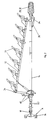
- FIG. 1 shows a semi-mounted plough 10 having a main beam 12 which carries plough blades 13 and is supported on a wheel beam (drawbar) 14 in the convention manner.
- the plough is mountable on a tractor (not shown) by a headstock 16, again in conventional manner.
- the pivotal connection of the wheel beam 14 with the headstock 16 is provided with a first angle sensor 18 which monitors the angle of the beam 14 relative to the longitudinal axis of the tractor.
- a limit switch 20 is also provided at the pivotal connection of the beam 14 with the headstock 16. This monitors the vertical pivot position of the beam 14 relative to the headstock 16 and is in either an ON or OFF position, depending on whether or not the headstock 16 is raised or lowered on the tractor linkage.
- An offset linear sensor 22 monitors the lateral pivotal position of the plough beam 12 relative to the beam 14 and provides a signal in dependence on this.
- a further sensor 24 which is a steering wheel to beam angle sensor monitors the angle between a steering wheel 26 in a rear wheel assembly and the plough beam 12.
- the rear wheel assembly is provided with a sensor 28 ( Figures 4 and 5) for monitoring the distance travelled by the wheel 26 and therefore by the tractor towing the plough.
- a sensor 28 ( Figures 4 and 5) for monitoring the distance travelled by the wheel 26 and therefore by the tractor towing the plough.
- This is conveniently in the form of, for example, a toothed or castellated disc 30 mounted for rotation on the wheel 26 and a cooperating proximity sensor 32 which provides a train of pulses in response to rotation of the disc, the pulse count providing an indication of the distance travelled.
- the wheel nuts or fixings themselves can provide the train of pulses.
- the sensors 18 and 24 are conveniently simple potentiometers which provide an output voltage in dependence on the angular position.
- the offset sensor 22 is conveniently in the form of a bank of reed switches mounted on a turnover arm 34 of the plough and arranged to be closed in succession by a suitable means as the main beam 12 is moved towards the wheel beam 14, and opened in succession by reverse pivotal movement of the main beam 12 away from the wheel beam 14.
- Offset, or pivotal movement of the main beam 12 inwardly and outwardly towards and away from the wheel beam 14 is effected by a double-acting offset piston/cylinder unit 36.
- a steering cylinder 38 is used to steer the wheel 26 relative to the wheel beam 14
- a depth cylinder 42 which is mounted at the wheel end of the wheel beam 14 is used to control the wheel depth 26 by raising and lowering the wheel beam 14 relative to the wheel 26 and turnover cylinders 40 are used to effect turnover of the plough main beam 12, all of these cylinders being hydraulic, double-acting piston/cylinder units.
- a respective end proximity sensor 50, 52 ( Figures 4 and 5) is provided at each extreme turnover position of the plough main beam 12. Each sensor senses the position of the plough main beam 12 when it reaches its respective completed turnover position and generates a signal accordingly.
- a centre position proximity sensor 54 ( Figures 4 and 5) is also provided to sense when the plough beam 12 reaches its mid or centre position during turnover and generates a signal in response to the plough beam 12 reaching this centre position.
- the above-described sensors provide signals to a control circuit 55 which in turn controls the plough through a hydraulic circuit.
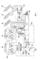
- FIG. 3 A schematic diagram of the hydraulic circuit is shown in Figure 3.
- the supply of hydraulic fluid is through a manifold block assembly 244 which contains a three-position proportional steering valve 220, a three-position offset/turnover directional valve 250, a three-position depth/furrow directional valve 200, a sensing valve 230 and a load valve 232.
- Fluid is supplied to the manifold block 244 through a pressure filter 234.
- the proportional steering valve 220 controls the supply of fluid through a dual over centre valve 246 to the steering cylinder 38.
- the depth/furrow directional valve 200 controls the supply of fluid through a further dual over centre valve 254 to the depth cylinder 42.
- the offset/turnover directional valve 250 in the manifold block 244 controls the flow of hydraulic fluid through a holding valve 252 to a six port diverter valve 248.
- the valve 248 determines whether fluid is supplied either to the offset cylinder 36 or, through a further valve 256 to the turnover cylinders 40.
- the valve 256 is a dual flow control and dual cross relief valve. Whilst the valve 248 determines which of the cylinders 36 and 40 are supplied with fluid, the valve 250 controls the direction of flow of the fluid to the cylinders.
- the valves 200, 220, 230, 232, 248 and 250 are all solenoid controlled valves.
- valve solenoids are controlled through valve drivers 300 and valve logic 112 by a control logic circuit 66, conveniently in the form of a microprocessor.
- the hydraulic system illustrated in Figure 3 can accommodate closed, open and load sensing hydraulic system connections.
- the load valve 232 When used on open centre hydraulic systems, the load valve 232 is used whilst the sensing port 202 is closed.
- the solenoid of the sensing valve 230 When the system is used on closed centre hydraulic systems, the solenoid of the sensing valve 230 is disconnected, the load valve 232 is omitted with its fluid line and the sensing port 202 being closed.
- the solenoid of the sensing valve 230 is connected and the load valve 232 is removed and the associated line closed.
- each of the three hydraulic systems can be used to their full advantage.
- the fuel saving of load sensing hydraulics can be used on the plough.
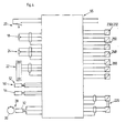
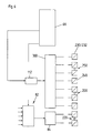
- FIG. 5 shows part of the control circuit for the plough control system.
- a 12-volt DC power supply from the tractor is passed through a supply filter 56 to provide power for the solenoid valves in the hydraulic circuit and through a stabilised power supply to provide a supply for the electrical circuit.
- the signal from the wheel beam to tractor angle sensor 18 is passed through a signal conditioning circuit 60 which generally filters out electrical noise and scales the signal to provide an output signal which varies over a desired range in response to changes in the input signal.
- This output signal is compared with a centre reference signal in a comparator 62, the output signal of which provides an indication of the direction of movement, i.e. to the left or right or straight ahead of the tractor, the resulting signal being stored in a memory 64 and applied to the control logic circuit 66 ( Figure 6).
- the output of the signal conditioning circuit 60 is also applied directly and through a position memory circuit 68 to respective inputs of a comparator 70 whose output is applied to the control logic circuit 66.
- the plough direction can alternatively be determined and stored in two other ways:
- the steering wheel to beam angle sensor 24, the offset sensor 22 and the distance travelled sensor 28 apply their output signals to respective signal conditioning circuits 72, 74 and 76 which operate in the same manner as the signal conditioning circuit 60.
- the output of the signal conditioning circuit 72 is applied to one input of a comparator 78, the other input which receives a preselected reference value, the output of the comparator being applied to the control logic circuit 66.
- the outputs of the signal conditioning circuits 60 and 72 are also applied to respective inputs of an error amplifier 80 whose outputs are applied to a command select circuit 82 which is also controlled by the control logic circuit 66.
- the command select circuit 82 controls a proportional valve driver 84 which controls the steering of the wheel 26 by way of the cylinder 36 to maintain the correct or desired steering angle.
- the output from the signal conditioning circuit 72 or alternatively 60 is also applied to a position memory circuit 86 whose output is applied to one input of an error amplifier 88.
- the other input of the error amplifier is connected to the output of the signal conditioning circuit 60, the error amplifier 88 providing an error signal in dependence upon the comparison of the drawer bar to tractor angle signal and the steering wheel to beam angle signal previously memorised by the position memory 86 on instructions from the control logic 66.
- the output signal of the error amplifier 88 is applied to the command select circuit 82 to control the steering angle of the wheel 26 on re-entry of the plough bladed into the ground after turnaround of the plough.
- the offset sensor signal from the signal conditioning circuit 74 is applied to a deployed position memory 90.
- This is controlled by the control logic circuit 66 to store the signal which is representative of the angle of the plough main beam 12 relative to the wheel beam 14 which was previously set by the operator for ploughing.
- the output of the memory 90 is applied to a deployed position comparator 92 which compares the memorised signal with the actual signal from the signal conditioning circuit 74 and provides an adjustment signal which is applied to the control logic circuit 66 and also is fed back to the deployed position memory 90.
- the output signal from the signal conditioning circuit 74 is also applied to one input of a stowed position comparator 94 which compares this value with a stowed position reference value to provide an output signal to the control logic circuit 66 which is indicative of the angle position of the plough main beam 12 relative to its stowed position.
- the distance signal output of the signal conditioning circuit 76 is applied to a distance counter 96 which counts the number of pulses and applies its count signal directly to one input of a distance comparator 98 and through a distance memory 100 to a second input of the distance comparator 98.
- the count which is stored in the distance memory 100 is controlled by the control logic circuit 66 which also receives the output comparison signal of the comparator 98.
- a reset signal can be applied from the control logic circuit 66 to the distance counter 96.
- the limit switch 20 is also connected to the control logic 66 through a conditioning circuit 99.
- the angle between the drawbar 14 and tractor (headstock 16) (sensor 18), the angle between the steering wheel 26 and the wheel beam 14 (sensor 24) the offset or deployed angle of the main beam 12 relative to the wheel beam 14 (offset sensor 22) have all been preselected and representative signals have been stored in the position memories 68, 86 and 90.
- the angle between the drawbar and tractor and the angle between the steering wheel 26 and the wheel beam 14 may be the same with the wheel running parallel to the direction of movement of the towing tractor (referred to as the parallel angle), although the action of the plough blades in the ground means that the effect of drag might require the angles to be different.
- the wheel beam 14 is angled to the left of the tractor as viewed in the direction of movement of the tractor.
- Control of the control system by an operator is effected through a control box in the tractor cab and as the plough approaches the end of its furrow the operator first of all actuates a switch to raise the headstock 16 on the tractor linkage.
- This changes the angular position of the plough headstock relative to the wheel beam 14 which results in the limit switch 20 being closed, applying a signal to the control logic 66 to set a sequence of operations in motion.
- control logic circuit 66 After a preselected time delay which is controlled by a timer in the control logic circuit 66, the control logic circuit 66 applies a signal to the valve logic circuit 112 which in turn controls the depth/furrow directional valve to actuate cylinder 42 to raise the wheel beam 14 to lift the plough blades clear of the ground.
- the raising of the wheel beam 14 may be carried out after the plough has travelled a predetermined distance measured by the distance measurement sensor 28.
- the preselected distance count is stored in the control logic 100.
- the distance counter 96 is reset by a signal from the control logic and the distance comparator 98 then compares the count from the counter 96 with that stored in the distance memory 100. Once the distance counter 96 has counted to the reference level of the distance memory 100, the distance comparator 98 applies a signal to the control logic which then causes the cylinder 42 to be actuated to raise the wheel beam 14 relative to the wheel 26.
- time delay or distance count may be optional, at the control of the operator.
- length of the time delay or distance count may also be preselected by the operator.
- the logic circuit 66 actuates the steering cylinder 38 through the proportional steering valve 220 to steer the wheel to the same angle as the headstock 16 to wheel beam angle If one assumes that the tractor has reached the end of a ploughing line and the operator is turning to the left to commence a new, parallel ploughing line, the steering wheel 26 will turn to the left with the tractor.
- the steering valve 220 is energised to steer the wheel 26.
- the relationship between the headstock to wheel beam angle and the steering wheel to wheel beam angle is referred to as the trailer angle and is maintained throughout the tractor turn.
- the operator begins to steer the tractor and plough combination towards the new ploughing direction.
- the steering cylinder 38 has priority over the turnover, offset and depth cylinders 42, hydraulic fluid being provided to the steering cylinder, where needed, in preference to the others.
- the control logic circuit 66 actuates the offset/turnover valve 248 and the offset/turnover directional valve 250 to apply fluid to the offset cylinder 36 to fold the plough main beam 12 in towards the wheel beam 14.
- the direction of flow of fluid to the offset cylinder 36 is determined by the position of the valve 250.
- This folding of main beam 12 from its working position towards the wheel beam 14 is monitored by the offset sensor 22 whose output signal is applied to the stowed position comparator 94.
- the controlled logic circuit 66 controls the valves 248 and 250 to actuate the turnover cylinders 40 to turn over the plough.
- the direction of turnover is again controlled by the position of the valve 250. Since the valves 248 and 250 control both the folding and turnover of the plough it will be appreciated that it is not possible for the turnover to commence while the plough beam 12 is being folded towards the wheal beam 14.
- Both the folding and turnover of the plough beam 12 can be manually over-ridden by the operator.
- the control logic circuit 66 responds to actuate the cylinder 38 to steer the wheel 26 back towards its operating angle, previously stored in the position memory 86. This subsequent steering of the wheel 26 is monitored by the sensor 24 with hydraulic fluid flow priority being given to the cylinder 38.
- the angle between the headstock 16 and the wheel beam 14 continues to change and, as described above, the signals from the sensors 18 and 24 are used by the control logic circuit 66 to cause the steering cylinder 68 to adjust the steering of the wheel 26.
- the turnover sequence continues, if it has not already been completed, until the cylinders 40 have completed the turnover of the plough beam 12.
- turnover of the plough continues until the relevant proximity end sensor 50,52 senses completion of the turnover and the control logic circuit 66 stops actuation of the turnover cylinders 40.
- the actuation of the turnover cylinders 40 is halted by the control logic circuit 66 when the centre proximity sensor 54 senses that the plough beam 12 is in its central position, midway between the extreme turnover positions, and applies a signal to the control logic circuit 66.
- the plough beam 12 then remains in this centre position until the operator recommences the turnover sequence, the control logic circuit 66 then actuating the turnover cylinders 40 to continue turnover until a signal is generated by the relevant end proximity sensor 50, 52, indicating that the turnover sequence is completed.
- the control logic circuit 66 actuates the valves 248 and 250 to actuate the offset cylinder 36 to move the main beam 12 away from the wheel beam 14 into its working position. Again, the angle between the main beam 12 and wheel beam 14 is monitored by the offset sensor 22.
- the output signal from the signal conditioning circuit 74 is compared with the deployed position reference in the memory 90 by the comparator 92.
- the output signal from the comparator 92 is monitored by the control logic circuit 66 until it indicates that the main beam 12 has reached it working position, whereupon the control logic circuit 66 stops actuation of the offset cylinder 36.
- the operator lowers the tractor linkage. This opens the limit switch 20 which is sensed by the control logic circuit 66. After a preselected time delay or a predetermined distance measurement by the distance sensor 28, the control logic circuit 66 actuates valve 200 to actuate the depth cylinder 42 and lower the wheel beam 14 relative to the wheel 26 back into its working position where the plough blades penetrate the ground for ploughing.
- the choice of a time delay or distance measurement can be optionally set by the operator who may also preselect the actual distance or time delay, depending on the system used.
- the plough blades Once the plough blades enter the ground, they exert a drag on the tractor and cause the wheel beam 14 to pivot such that the angle sensed by the angle sensor 24 changes.
- the steering cylinder 38 is actuated under the control of the control logic circuit 66 to steer the wheel 26 in a direction to maintain the preselected and stored angles sensed by the sensors 18 and 24 .
- Control of the control system is effected from the tractor cab by the operator.
- the control system reduces the workload for the operator, giving a faster and more efficient turnaround operation, increasing the time that the plough is in work.
- control systems can be over-ridden by the operator who can alter the depth of the rear of the plough and trim the position of the front furrow from the tractor cab.
- the positions of the plough front body, wheel beam angle with respect to the tractor and effective length of the plough is stored electronically by the operator whilst ploughing and is effected by the simple pressing of a switch on a control box in the cab.
- An emergency stop button can be provided which halts all electro-hydraulic functions and can be reset by the operator. Control of the angles monitored by the sensors 18 and 24 enables the operator to vary the ploughing width from the cab and store these values in the memories so that the plough can be returned to these values simply and automatically.
Landscapes
- Life Sciences & Earth Sciences (AREA)
- Engineering & Computer Science (AREA)
- Mechanical Engineering (AREA)
- Soil Sciences (AREA)
- Environmental Sciences (AREA)
- Guiding Agricultural Machines (AREA)
- Control Of Eletrric Generators (AREA)
- Control Of Position, Course, Altitude, Or Attitude Of Moving Bodies (AREA)
- Separation By Low-Temperature Treatments (AREA)
- Electrically Driven Valve-Operating Means (AREA)
- Soil Working Implements (AREA)
Claims (30)
- Ein Steuersystem für einen Aufsattelpflug mit:dadurch gekennzeichnet, dass das System Folgendes umfasst:einem Dreipunktbock (16) zum Anbau an einen Zugschlepper;einem Pflugradbaum (14), der am besagten Dreipunktbock (16) schwenkbar montiert ist;einem Lenkrad (26), das am besagten Radbaum angebracht ist, um den besagten Pflug zu lenken;und einem Hauptpflugbaum (12), der am besagten Radbaum (14) schwenkbar montiert und mit einer Mehrzahl von Pflugkörpern (13) ausgerüstet ist;ein erstes Messmittel (18), um den Winkel des Pflugradbaums (14) mit Hinsicht auf den besagten Dreipunktbock zu überwachen und ein erstes Radbaumsignal abzugeben, das dem Bockwinkel entspricht;ein zweites Messmittel (24), um den Winkel des besagten Lenkrads (26) des Pflugs mit Hinsicht auf den besagten Radbaum (14) des Pflugs zu überwachen und ein zweites Lenksignal abzugeben, das dem Lenkwinkel entspricht;sowie Steuermittel (55), um den besagten Radbaum und die Lenksignale zu überwachen und den Winkel des Lenkrads (26) dementsprechend zu steuern.
- Ein Steuersystem nach Anspruch 1, dessen besagte Steuermittel (55) dafür eingesetzt werden können, um den überwachten Lenkwinkel des besagten Lenkrads (26) mit einem vorgewählten Wert zu vergleichen und abhängig von diesem Wert zu steuern.
- Ein Steuersystem nach Anspruch 1 oder Anspruch 2, dessen besagte Steuermittel (55) dafür eingesetzt werden können, um den Lenkwinkel des besagten Lenkrads (26) abhängig von dem überwachten Bockwinkel des besagten Radbaums (14) einzustellen.
- Ein Steuersystem nach den vorstehenden Ansprüchen, dessen besagte Steuermittel (55) zur Lenkwinkelsteuerung des Lenkrads (26) eingesetzt werden können, um die effektive Arbeitsbreite des Pflugs auf diese Weise zu steuern.
- Ein Steuersystem nach den vorstehenden Ansprüchen, dessen besagte Steuermittel (55) zur Lenkwinkelsteuerung des Lenkrads (26) eingesetzt werden können, um den besagten Pflug auf diese Weise in eine mit Hinsicht auf die Zugrichtung des besagten Dreipunktbocks durch den besagten Schlepper vorgewählte Richtung zu lenken.
- Ein Steuersystem nach den vorstehenden Ansprüchen, das ferner ein Mittel (20) zur Überwachung der vertikalen Stellung des besagten Dreipunktbocks (16) mit Hinsicht auf den besagten Radbaum (14) umfasst und in Reaktion auf das Heben und Senken des besagten Bocks (16) ein Elevationssignal abgibt.
- Ein Steuersystem nach Anspruch 6, das Hubmittel (42) umfasst, um den besagten Radbaum (14) mit Hinsicht auf das besagte Lenkrad (26) zu heben und zu senken.
- Ein Steuersystem nach Anspruch 7, dessen besagte Steuermittel (55) zur Betätigung des besagten Hubmittels (42) eingesetzt werden können, um den besagten Radbaum (14) in Reaktion auf das besagte Elevationssignal des besagten Bocküberwachungsmittels (20), wodurch entweder das Heben oder das Senken des besagten Dreipunktbocks (16) gemeldet wird, mit Hinsicht auf das besagte Lenkrad (26) zu heben oder zu senken.
- Ein Steuersystem nach Anspruch 8, das ferner Folgendes umfasst:ein Zeitstellmittel zur Speicherung einer vorgewählten Hubverzögerung;und dessen besagte Steuermittel (55) zur Betätigung des besagten Hubmittels (42) zum Heben oder Senken des besagten Radbaums (14) mit Hinsicht auf das besagte Lenkrad (26) nach besagter vorgewählter Verzögerung in Reaktion auf das besagte Elevationssignal des besagten Bocküberwachungsmittels (20) eingesetzt werden können, wodurch entweder das Heben oder das Senken des besagten Dreipunktbocks (16) angezeigt wird.
- Ein Steuersystem nach vorstehenden Ansprüchen, das ferner ein Distanzüberwachungsmittel (28) umfasst, um die Umdrehung des besagten Lenkrads (26) zu überwachen und ein Distanzsignal abzugeben, das der von besagtem Lenkrad zurückgelegten Strecke entspricht.
- Ein Steuersystem nach Anspruch 10, das in Verbindung mit Anspruch 8 zusätzlich noch Folgendes umfasst:ein Speichermittel zur Speicherung der vorgewählten Hubstrecke des besagten Rads;und dessen besagte Steuermittel (55) zur Betätigung des besagten Hubmittels (42) zum Heben oder Senken des besagten Radbaums (14) mit Hinsicht auf das besagte Lenkrad (26) eingesetzt werden können, nachdem das besagte Rad die besagte vorgewählte Strecke in Reaktion auf das besagte Elevationssignal des besagten Bocküberwachungsmittels (20) zurückgelegt hat, wodurch das Heben bzw. Senken des besagten Dreipunktbocks gemeldet wird.
- Ein Steuersystem nach Anspruch 11, das ferner Folgendes umfasst:Rückstellmittel zur Rückstellung des besagten Distanzüberwachungsmittels (28) in Reaktion auf das besagte Elevationssignal des besagten Bocküberwachungsmittels (20);und Vergleichsmittel zum Vergleich des besagten Distanzsignals des besagten Distanzüberwachungsmittels mit. der besagten, gespeicherten, vorgewählten Hubstrecke;und dessen besagte Steuermittel (55) zur Betätigung des besagten Hubmittels (42) zum Heben oder Senken des besagten Radbaums (14) abhängig von besagtem Vergleich eingesetzt werden können.
- Ein Steuersystem nach vorstehenden Ansprüchen, dessen besagte Steuermittel (55) zur Lenkung des besagten Lenkrads eingesetzt werden können, damit weitgehend der gleiche Lenk- und Bockwinkel beibehalten werden.
- Ein Steuersystem nach vorstehenden Ansprüchen, das ferner Folgendes umfasst:ein Verstellmittel (36), um den besagten Hauptpflugbaum (12) zwischen einer ersten ausgefahrenen Position und einer zweiten, mit Hinsicht auf den besagten Radbaum (14) eingefahrenen Position zu bewegen, wobei der besagte Hauptpflugbaum (12) in der ersten ausgefahrenen Position von dem besagten Radbaum (14) in eine Arbeitsposition und in der besagten zweiten eingefahrenen Position von dem besagten Radbaum (14) in eine nichtarbeitende Position neben dem besagten Radbaum geschwenkt wird.
- Ein Steuersystem nach Anspruch 14, dessen besagte Steuermittel (55) zur Betätigung des besagten Verstellmittels (36) eingesetzt werden können, um den besagten Hauptpflugbaum (12) zwischen der besagten ersten ausgefahrenen und zweiten eingefahrenen Position zu bewegen.
- Ein Steuersystem nach Anspruch 15, das ferner Folgendes umfasst:Verzögerungsmittel zur Speicherung einer vorgewählten Einfahrverzögerung;und dessen besagte Steuermittel (55) zur Betätigung des besagten Verstellmittels (36) eingesetzt werden können, um den besagten Hauptpflugbaum (12) mit Hinsicht auf den besagten Radbaum (14) in Reaktion auf das besagte Bocksignal, das das Heben bzw. Senken des besagten Dreipunktbocks (16) anzeigt, nach besagter vorgewählter Einfahrverzögerung von der besagten ersten ausgefahrenen Position zu einer besagten zweiten eingefahrenen Position oder von der besagten zweiten eingefahrenen Position zu der besagten ersten ausgefahrenen Position zu bewegen.
- Ein Steuersystem nach Anspruch 9 und Anspruch 16, dessen besagte vorgewählte Einfahrverzögerung länger ist als die besagte vorgewählte Hubverzögerung.
- Ein Steuersystem nach Anspruch 7 und vorstehenden Ansprüchen 14 bis 17, dessen besagte Steuermittel (55) zur Betätigung des besagten Verstellmittels (36) eingesetzt werden können, um den besagten Hauptpflugbaum (12) mit Hinsicht auf den besagten Radbaum (14) in Reaktion auf die Betätigung des besagten Hubmittels (42) zum Heben oder Senken des besagten Radbaums (14) von der besagten ersten ausgefahrenen Position zu der besagten zweiten eingefahrenen Position oder von der besagten zweiten eingefahrenen Position zu der besagten ersten ausgefahrenen Position zu bewegen.
- Ein Steuersystem nach Anspruch 18, dessen besagte Steuermittel (55) zur Betätigung des besagten Verstellmittels (36) eingesetzt werden können, um den besagten Hauptpflugbaum (12) mit Hinsicht auf den besagten Radbaum (14) von der besagten ersten ausgefahrenen Position zu der besagten zweiten eingefahrenen Position oder von der besagten zweiten eingefahrenen Position zu der besagten ersten ausgefahrenen Position zu bewegen, nachdem nach der Betätigung des besagten Hubmittels (42), um den besagten Radbaum (14) zu heben bzw. zu senken, eine vorgewählte Verzögerung verflossen ist.
- Ein Steuersystem nach Anspruch 15, das ferner Folgendes umfasst:ein Speichermittel zum Speichern einer vorgewählten Einfahrstrecke des besagten Rads (26);und dessen besagte Steuermittel (55) zur Betätigung des besagten Verstellmittels (36) eingesetzt werden können, um den besagten Hauptpflugbaum (12) mit Hinsicht auf den besagten Radbaum (14) von der besagten ersten ausgefahrenen Position zu der besagten zweiten eingefahrenen Position oder von der besagten zweiten eingefahrenen Position zu der besagten ersten ausgefahrenen Position zu bewegen, nachdem das besagte Rad (26) die besagte vorgewählte Einfahrstrecke in Reaktion auf das besagte Bocksignal, mit dem entweder das Heben oder das Senken des besagten Dreipunktbocks (16) angezeigt wird, zurückgelegt hat.
- Ein Steuersystem nach Anspruch 18, dessen besagte Steuermittel (55) zur Betätigung des besagten Verstellmittels (36) eingesetzt werden können, um den besagten Hauptpflugbaum (12) mit Hinsicht auf den besagten Radbaum (14) von der besagten ersten ausgefahrenen Position zu der besagten zweiten eingefahrenen Position oder von der besagten zweiten eingefahrenen Position zu der besagten ersten ausgefahrenen Position über eine vorgewählte Strecke nach Betätigung des besagten Hubmittels (42) zum Heben oder Senken des besagten Radbaums (14) zu bewegen.
- Ein Steuersystem nach Anspruch 11 und Anspruch 20, dessen besagte vorgewählte Einfahrdistanz länger ist als die besagte vorgewählte Hubdistanz.
- Ein Steuersystem nach Ansprüchen 14 bis 22, das ferner Folgendes umfasst:Verstellkontrollmittel (22, 50, 52, 54), mit denen die Verstellung des besagten Hauptpflugbaums (12) mit Hinsicht auf den besagten Radbaum (14) überwacht und ein dementsprechendes Verstellsignal abgegeben wird.
- Ein Steuersystem nach Anspruch 23, dessen besagte Verstellkontrollmittel (22, 50, 52, 54) zur Abgabe eines ausgefahrenen Verstellsignals und eines eingefahrenen Verstellsignals eingesetzt werden können, sobald sich der Hauptpflugbalken (12) in die besagte erste ausgefahrene Position bzw. in die besagte zweite eingefahrene Position bewegt.
- Ein Steuersystem nach Anspruch 24, dessen besagte Verstellkontrollmittel (22, 50, 52, 54) zur Abgabe eines weiteren Verstellsignals eingesetzt werden können, sobald sich der besagte Hauptpflugbalken (12) in eine weitere versetzte Position zwischen der besagten ersten ausgefahrenen Position und der besagten zweiten eingefahrenen Position bewegt.
- Ein Steuersystem nach Anspruch 24 oder Anspruch 25, dessen besagte Steuermittel (55) zur Betätigung des besagten Verstellmittels (36) eingesetzt werden können, um den besagten Hauptpflugbalken (12) von der besagten ersten ausgefahrenen Position zu einer besagten zweiten eingefahrenen Position zu bewegen und das besagte Verstelimittel (36) in Reaktion auf das besagte eingefahrene Verstellsignal auszuschalten.
- Ein Steuersystem nach Ansprüchen 24, 25 oder 26, dessen besagte Steuermittel (55) zur Betätigung des besagten Verstellmittels (36) eingesetzt werden können, um den besagten Hauptpflugbalken (12) zwischen der besagten ersten ausgefahrenen Position und der besagten zweiten eingefahrenen Position zu bewegen und das besagte Verstellmittel (36) in Reaktion auf ein weiteres besagtes Verstellsignal auszuschalten.
- Ein Steuersystem nach vorstehenden Ansprüchen, das ferner ein Drehmittel (40) umfasst, das zur Drehung des besagten Hauptpflugbalkens (12) eingesetzt werden kann.
- Ein Steuersystem nach Anspruch 28 in Verbindung mit Ansprüchen 23 bis 27, dessen besagte Steuermittel (55) zur Betätigung des besagten Drehmittels (40) eingesetzt werden können, um den besagten Hauptpflugbalken (12) in Reaktion auf ein vorgewähltes Signal der besagten Verstellkontrollmittel (22, 50, 52, 54) zu drehen.
- Ein Steuersystem nach Anspruch 29, dessen besagtes vorgewähltes Signal das besagte eingefahrene Verstellsignal ist.
Applications Claiming Priority (2)
| Application Number | Priority Date | Filing Date | Title |
|---|---|---|---|
| GBGB9524419.0A GB9524419D0 (en) | 1995-11-29 | 1995-11-29 | Control system for a plough |
| GB9524419 | 1995-11-29 |
Publications (3)
| Publication Number | Publication Date |
|---|---|
| EP0776597A2 EP0776597A2 (de) | 1997-06-04 |
| EP0776597A3 EP0776597A3 (de) | 1998-06-10 |
| EP0776597B1 true EP0776597B1 (de) | 2002-04-03 |
Family
ID=10784644
Family Applications (1)
| Application Number | Title | Priority Date | Filing Date |
|---|---|---|---|
| EP96308509A Expired - Lifetime EP0776597B1 (de) | 1995-11-29 | 1996-11-26 | Pflugsteuersystem |
Country Status (4)
| Country | Link |
|---|---|
| EP (1) | EP0776597B1 (de) |
| AT (1) | ATE215302T1 (de) |
| DE (1) | DE69620352D1 (de) |
| GB (1) | GB9524419D0 (de) |
Cited By (3)
| Publication number | Priority date | Publication date | Assignee | Title |
|---|---|---|---|---|
| US11122725B2 (en) | 2017-06-21 | 2021-09-21 | Honey Bee Manufacturing Ltd. | Tillage apparatuses and related methods |
| US12114584B2 (en) | 2020-10-30 | 2024-10-15 | Honey Bee Manufacturing Ltd. | Agricultural implement with tine assembly |
| US12364176B2 (en) | 2021-06-16 | 2025-07-22 | Honey Bee Manufacturing Ltd. | Agricultural apparatuses and related methods |
Families Citing this family (4)
| Publication number | Priority date | Publication date | Assignee | Title |
|---|---|---|---|---|
| FR2944180A1 (fr) * | 2009-04-08 | 2010-10-15 | Kuhn Huard Sa | Charrue reversible avec dispositif de reduction de pression |
| EP2875707B1 (de) | 2013-10-17 | 2016-06-15 | Moro Aratri S.R.L. | Transport- und Arbeitssystem für Tragpflug |
| FR3092961B1 (fr) * | 2019-02-21 | 2021-06-11 | Kuhn Huard Sa | Charrue avec un dispositif de compensation de l'effort latéral en cours de labour |
| CN117981506B (zh) * | 2024-02-27 | 2026-02-10 | 江苏大学 | 一种组合式旋耕一体机及其控制方法 |
Family Cites Families (5)
| Publication number | Priority date | Publication date | Assignee | Title |
|---|---|---|---|---|
| US3511317A (en) * | 1967-04-19 | 1970-05-12 | Massey Ferguson Inc | Turnover semi-mounted plow |
| FR2329174A1 (fr) * | 1975-10-28 | 1977-05-27 | Rabewerk Clausing Heinrich | Charrue brabant semi-portee avec dispositif de direction |
| DD250651A1 (de) * | 1986-07-07 | 1987-10-21 | Fortschritt Veb K | Mehrfurchiger pflug |
| DE3900086A1 (de) * | 1989-01-03 | 1990-07-05 | Norbert Kolb | Verstelleinrichtung mit sensor fuer ein arbeitsgeraet, insbesondere drehpflug |
| DE9110735U1 (de) * | 1991-08-30 | 1991-11-14 | H. Niemeyer Söhne GmbH & Co KG, 4446 Hörstel | Aufsattelpflug |
-
1995
- 1995-11-29 GB GBGB9524419.0A patent/GB9524419D0/en active Pending
-
1996
- 1996-11-26 AT AT96308509T patent/ATE215302T1/de not_active IP Right Cessation
- 1996-11-26 EP EP96308509A patent/EP0776597B1/de not_active Expired - Lifetime
- 1996-11-26 DE DE69620352T patent/DE69620352D1/de not_active Expired - Lifetime
Cited By (4)
| Publication number | Priority date | Publication date | Assignee | Title |
|---|---|---|---|---|
| US11122725B2 (en) | 2017-06-21 | 2021-09-21 | Honey Bee Manufacturing Ltd. | Tillage apparatuses and related methods |
| US11324153B2 (en) | 2017-06-21 | 2022-05-10 | Honey Bee Manufacturing Ltd. | Tillage apparatuses and related methods |
| US12114584B2 (en) | 2020-10-30 | 2024-10-15 | Honey Bee Manufacturing Ltd. | Agricultural implement with tine assembly |
| US12364176B2 (en) | 2021-06-16 | 2025-07-22 | Honey Bee Manufacturing Ltd. | Agricultural apparatuses and related methods |
Also Published As
| Publication number | Publication date |
|---|---|
| ATE215302T1 (de) | 2002-04-15 |
| EP0776597A3 (de) | 1998-06-10 |
| EP0776597A2 (de) | 1997-06-04 |
| DE69620352D1 (de) | 2002-05-08 |
| GB9524419D0 (en) | 1996-01-31 |
Similar Documents
| Publication | Publication Date | Title |
|---|---|---|
| US7721830B2 (en) | Tractor with automatic steering arrangement | |
| US6058342A (en) | Precision control of implement position/motion | |
| US5810095A (en) | System for controlling the position of an implement attached to a work vehicle | |
| US4802545A (en) | Steering control system for articulated vehicle | |
| EP0507232B1 (de) | Steuersystem für Schlepper mit angehängtem Arbeitsgerät | |
| DE10309700B4 (de) | Austrageinrichtung einer landwirtschaftlichen Erntemaschine | |
| EP2022306B1 (de) | Steuerungssystem zum Lenken eines an ein landwirtschaftliches Nutzfahrzeug angekoppelten Anbaugeräts | |
| AU2009201179B2 (en) | Tractor with automatic steering arrangement | |
| CA2109173C (en) | Position feedback mechanism for an implement | |
| US4178741A (en) | Safety system for riding mower | |
| US4373603A (en) | Automatic crab steering | |
| DE102010021178B3 (de) | Kraftfahrzeug mit Achsschenkel- und Knicklenkung | |
| BR112014005142B1 (pt) | Veículo autoimpulsionado e direcionável incluindo um mecanismo de direcionamento | |
| EP1364573B1 (de) | Heuwerbungsmaschine | |
| EP1405556A2 (de) | Selbstfahrendes Grossflächenmähwerk | |
| US5894894A (en) | Control of a semi-mounted plough | |
| US5755291A (en) | Operator interface for vehicle control system with slip regulation | |
| EP0776597A2 (de) | Pflugsteuersystem | |
| US4077651A (en) | Hydraulic steering for plow | |
| US11780494B2 (en) | Control apparatus for hydraulically steered wheels of a trailing vehicle operable in locked and self steering configurations | |
| DE10138563B4 (de) | Rad-Straßenfertiger und Verfahren zum Lenken eines Rad-Straßenfertigers | |
| EP1082887B1 (de) | Einrichtung zum Wenden eines an einem landwirtschaftlichen Fahrzeug angelenkten Anbaugeräts, insbesondere eines Drehpfluges | |
| DE69217278T2 (de) | Verbesserung für landwirtschaftliche Maschinen wie Aufsattelpflüge mit einer Hilfsantriebsvorrichtung | |
| US20220361393A1 (en) | Winged Agricultural Implement with Steerable Transport Wheels | |
| US6041867A (en) | Hitch initialization control system |
Legal Events
| Date | Code | Title | Description |
|---|---|---|---|
| PUAI | Public reference made under article 153(3) epc to a published international application that has entered the european phase |
Free format text: ORIGINAL CODE: 0009012 |
|
| AK | Designated contracting states |
Kind code of ref document: A2 Designated state(s): AT DE DK FR GB NL SE |
|
| PUAL | Search report despatched |
Free format text: ORIGINAL CODE: 0009013 |
|
| AK | Designated contracting states |
Kind code of ref document: A3 Designated state(s): AT DE DK FR GB NL SE |
|
| 17P | Request for examination filed |
Effective date: 19981118 |
|
| 17Q | First examination report despatched |
Effective date: 19990915 |
|
| GRAG | Despatch of communication of intention to grant |
Free format text: ORIGINAL CODE: EPIDOS AGRA |
|
| GRAG | Despatch of communication of intention to grant |
Free format text: ORIGINAL CODE: EPIDOS AGRA |
|
| GRAG | Despatch of communication of intention to grant |
Free format text: ORIGINAL CODE: EPIDOS AGRA |
|
| GRAH | Despatch of communication of intention to grant a patent |
Free format text: ORIGINAL CODE: EPIDOS IGRA |
|
| GRAH | Despatch of communication of intention to grant a patent |
Free format text: ORIGINAL CODE: EPIDOS IGRA |
|
| REG | Reference to a national code |
Ref country code: GB Ref legal event code: IF02 |
|
| GRAA | (expected) grant |
Free format text: ORIGINAL CODE: 0009210 |
|
| AK | Designated contracting states |
Kind code of ref document: B1 Designated state(s): AT DE DK FR GB NL SE |
|
| PG25 | Lapsed in a contracting state [announced via postgrant information from national office to epo] |
Ref country code: NL Free format text: LAPSE BECAUSE OF FAILURE TO SUBMIT A TRANSLATION OF THE DESCRIPTION OR TO PAY THE FEE WITHIN THE PRESCRIBED TIME-LIMIT Effective date: 20020403 Ref country code: FR Free format text: LAPSE BECAUSE OF FAILURE TO SUBMIT A TRANSLATION OF THE DESCRIPTION OR TO PAY THE FEE WITHIN THE PRESCRIBED TIME-LIMIT Effective date: 20020403 Ref country code: AT Free format text: LAPSE BECAUSE OF FAILURE TO SUBMIT A TRANSLATION OF THE DESCRIPTION OR TO PAY THE FEE WITHIN THE PRESCRIBED TIME-LIMIT Effective date: 20020403 |
|
| REF | Corresponds to: |
Ref document number: 215302 Country of ref document: AT Date of ref document: 20020415 Kind code of ref document: T |
|
| REF | Corresponds to: |
Ref document number: 69620352 Country of ref document: DE Date of ref document: 20020508 |
|
| PG25 | Lapsed in a contracting state [announced via postgrant information from national office to epo] |
Ref country code: SE Free format text: LAPSE BECAUSE OF FAILURE TO SUBMIT A TRANSLATION OF THE DESCRIPTION OR TO PAY THE FEE WITHIN THE PRESCRIBED TIME-LIMIT Effective date: 20020703 Ref country code: DK Free format text: LAPSE BECAUSE OF FAILURE TO SUBMIT A TRANSLATION OF THE DESCRIPTION OR TO PAY THE FEE WITHIN THE PRESCRIBED TIME-LIMIT Effective date: 20020703 |
|
| PG25 | Lapsed in a contracting state [announced via postgrant information from national office to epo] |
Ref country code: DE Free format text: LAPSE BECAUSE OF FAILURE TO SUBMIT A TRANSLATION OF THE DESCRIPTION OR TO PAY THE FEE WITHIN THE PRESCRIBED TIME-LIMIT Effective date: 20020704 |
|
| NLV1 | Nl: lapsed or annulled due to failure to fulfill the requirements of art. 29p and 29m of the patents act | ||
| EN | Fr: translation not filed | ||
| PLBE | No opposition filed within time limit |
Free format text: ORIGINAL CODE: 0009261 |
|
| STAA | Information on the status of an ep patent application or granted ep patent |
Free format text: STATUS: NO OPPOSITION FILED WITHIN TIME LIMIT |
|
| 26N | No opposition filed |
Effective date: 20030106 |
|
| PGFP | Annual fee paid to national office [announced via postgrant information from national office to epo] |
Ref country code: FR Payment date: 20041109 Year of fee payment: 9 |
|
| PGFP | Annual fee paid to national office [announced via postgrant information from national office to epo] |
Ref country code: GB Payment date: 20101124 Year of fee payment: 15 |
|
| GBPC | Gb: european patent ceased through non-payment of renewal fee |
Effective date: 20121126 |
|
| PG25 | Lapsed in a contracting state [announced via postgrant information from national office to epo] |
Ref country code: GB Free format text: LAPSE BECAUSE OF NON-PAYMENT OF DUE FEES Effective date: 20121126 |