EP0776499B1 - Content-based haptic input device for video - Google Patents
Content-based haptic input device for video Download PDFInfo
- Publication number
- EP0776499B1 EP0776499B1 EP95929588A EP95929588A EP0776499B1 EP 0776499 B1 EP0776499 B1 EP 0776499B1 EP 95929588 A EP95929588 A EP 95929588A EP 95929588 A EP95929588 A EP 95929588A EP 0776499 B1 EP0776499 B1 EP 0776499B1
- Authority
- EP
- European Patent Office
- Prior art keywords
- haptic feedback
- data
- input device
- viewer
- generating
- Prior art date
- Legal status (The legal status is an assumption and is not a legal conclusion. Google has not performed a legal analysis and makes no representation as to the accuracy of the status listed.)
- Expired - Lifetime
Links
Images



Classifications
-
- G—PHYSICS
- G06—COMPUTING OR CALCULATING; COUNTING
- G06F—ELECTRIC DIGITAL DATA PROCESSING
- G06F3/00—Input arrangements for transferring data to be processed into a form capable of being handled by the computer; Output arrangements for transferring data from processing unit to output unit, e.g. interface arrangements
- G06F3/01—Input arrangements or combined input and output arrangements for interaction between user and computer
- G06F3/016—Input arrangements with force or tactile feedback as computer generated output to the user
-
- G—PHYSICS
- G06—COMPUTING OR CALCULATING; COUNTING
- G06F—ELECTRIC DIGITAL DATA PROCESSING
- G06F3/00—Input arrangements for transferring data to be processed into a form capable of being handled by the computer; Output arrangements for transferring data from processing unit to output unit, e.g. interface arrangements
- G06F3/01—Input arrangements or combined input and output arrangements for interaction between user and computer
- G06F3/03—Arrangements for converting the position or the displacement of a member into a coded form
- G06F3/033—Pointing devices displaced or positioned by the user, e.g. mice, trackballs, pens or joysticks; Accessories therefor
- G06F3/0362—Pointing devices displaced or positioned by the user, e.g. mice, trackballs, pens or joysticks; Accessories therefor with detection of one-dimensional [1D] translations or rotations of an operating part of the device, e.g. scroll wheels, sliders, knobs, rollers or belts
-
- G—PHYSICS
- G11—INFORMATION STORAGE
- G11B—INFORMATION STORAGE BASED ON RELATIVE MOVEMENT BETWEEN RECORD CARRIER AND TRANSDUCER
- G11B27/00—Editing; Indexing; Addressing; Timing or synchronising; Monitoring; Measuring tape travel
- G11B27/02—Editing, e.g. varying the order of information signals recorded on, or reproduced from, record carriers
-
- G—PHYSICS
- G11—INFORMATION STORAGE
- G11B—INFORMATION STORAGE BASED ON RELATIVE MOVEMENT BETWEEN RECORD CARRIER AND TRANSDUCER
- G11B27/00—Editing; Indexing; Addressing; Timing or synchronising; Monitoring; Measuring tape travel
- G11B27/02—Editing, e.g. varying the order of information signals recorded on, or reproduced from, record carriers
- G11B27/022—Electronic editing of analogue information signals, e.g. audio or video signals
- G11B27/028—Electronic editing of analogue information signals, e.g. audio or video signals with computer assistance
-
- G—PHYSICS
- G11—INFORMATION STORAGE
- G11B—INFORMATION STORAGE BASED ON RELATIVE MOVEMENT BETWEEN RECORD CARRIER AND TRANSDUCER
- G11B27/00—Editing; Indexing; Addressing; Timing or synchronising; Monitoring; Measuring tape travel
- G11B27/02—Editing, e.g. varying the order of information signals recorded on, or reproduced from, record carriers
- G11B27/031—Electronic editing of digitised analogue information signals, e.g. audio or video signals
-
- G—PHYSICS
- G11—INFORMATION STORAGE
- G11B—INFORMATION STORAGE BASED ON RELATIVE MOVEMENT BETWEEN RECORD CARRIER AND TRANSDUCER
- G11B27/00—Editing; Indexing; Addressing; Timing or synchronising; Monitoring; Measuring tape travel
- G11B27/02—Editing, e.g. varying the order of information signals recorded on, or reproduced from, record carriers
- G11B27/031—Electronic editing of digitised analogue information signals, e.g. audio or video signals
- G11B27/034—Electronic editing of digitised analogue information signals, e.g. audio or video signals on discs
-
- G—PHYSICS
- G11—INFORMATION STORAGE
- G11B—INFORMATION STORAGE BASED ON RELATIVE MOVEMENT BETWEEN RECORD CARRIER AND TRANSDUCER
- G11B2220/00—Record carriers by type
- G11B2220/20—Disc-shaped record carriers
- G11B2220/25—Disc-shaped record carriers characterised in that the disc is based on a specific recording technology
- G11B2220/2537—Optical discs
- G11B2220/2587—Laser Discs; Optical disc using analog recording
-
- G—PHYSICS
- G11—INFORMATION STORAGE
- G11B—INFORMATION STORAGE BASED ON RELATIVE MOVEMENT BETWEEN RECORD CARRIER AND TRANSDUCER
- G11B27/00—Editing; Indexing; Addressing; Timing or synchronising; Monitoring; Measuring tape travel
- G11B27/02—Editing, e.g. varying the order of information signals recorded on, or reproduced from, record carriers
- G11B27/022—Electronic editing of analogue information signals, e.g. audio or video signals
- G11B27/026—Electronic editing of analogue information signals, e.g. audio or video signals on discs
-
- H—ELECTRICITY
- H01—ELECTRIC ELEMENTS
- H01H—ELECTRIC SWITCHES; RELAYS; SELECTORS; EMERGENCY PROTECTIVE DEVICES
- H01H3/00—Mechanisms for operating contacts
- H01H2003/008—Mechanisms for operating contacts with a haptic or a tactile feedback controlled by electrical means, e.g. a motor or magnetofriction
Definitions
- the present invention relates to haptic devices and more particularly, to an apparatus and method for providing the viewer of prerecorded visual data a way in which to receive sensory response which is correlated to and dependent on the prerecorded visual data through an input device which the viewer uses to browse the prerecorded visual data.
- knobs are commonly used as input devices to advance the images to cause the variable frame rate.
- the editor needs to move back and forth through the film or video material to determine the exact locations in to and out of which to cut, or edit. The his or her better control over this back and forth motion, the more effective the editing process.
- Such control ranges from hand-cranking film on open reels to sophisticated electronic control for video.
- Force-feedback circuitry is used to provide the operator with tactile feedback. Force-feedback may be defined as computer-controlled rate of friction or movement of an object.
- Force-feedback may be defined as computer-controlled rate of friction or movement of an object.
- U.S. Patent No. 5,185,561 to Good et al. discloses a torque motor being used as a tactile feedback device. In the case of a rotary knob, force-feedback could occur with an on-off brake, a variable brake, or a motor.
- a shuttle control is typically a spring-loaded rotary knob which controls frame rate: each unique position of the knob corresponds to a unique frame rate.
- a jog control is typically a free-turning rotary knob which controls frame position: progressive turning of the knob progressively increments or decrements from one frame to the next.
- a shuttle knob may be held in a non-zero static position and result in a non-zero fps rate while a jog knob must be moving for a non-zero fps rate.
- a shuttle is rate-control while jog is position-control.
- browesable video includes collections of stillframes, such as slide libraries are stored on videotape or disc. Since they are stored as a one-dimensional sequence, they also have no one correct viewing rate, but rather demand user-control for getting from one to another.
- US-A-5 185 561 shows a hand held, one dimensional, torque feedback device that is used to feel and manipulate computer generated visual information and associated torque forces.
- the device can also be used with a workstation generated display on problems which generate torque.
- the present invention provides a system and method for taking into account various aspects of the medium's content, such as edit points and other, boundaries. Moreover, the quality of the "route" through which one "travels," such as rockiness or uphill/downhill grades, are also movie content for which the present invention accounts.
- content-dependent data is composed and stored on a data storage device.
- the content-dependent data can either be manually entered or machine detectable and therefore entered automatically.
- viewer denotes end-user and operator denotes composer of content data and the whole program.
- an operator views the prerecorded image data on a visual data display at either its real-time speed or a slower or faster frame rate.
- the operator uses commands, the operator, through a content input device, sends content signals to a content data storage device where they are stored for use during a viewer's use of the apparatus.
- the viewer When a viewer views the prerecorded image data on the visual data display, the viewer is able to advance the frames by turning, for example a knob, which is the viewer input device.
- the viewer input device is in communication with a processor which is in turn in communication with the content data storage device.
- the viewer input device substantially immediately responds to the viewer's input in a haptic manner based on content-dependent data stored in data storage device which corresponds to the prerecorded visual data which is displayed on said visual data display at a particular time.
- the present invention includes a system and method for composing content data which is correlated with prerecorded visual data so that it can be played back as a viewer "browses" through the frames. Moreover, the present invention further includes a system and method for providing a viewer with the ability to experience in a haptic manner the content of the video as he or she uses the viewer input device to browse through the frames.
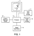
- FIG. 1 a combined system is shown. That is, the schematic includes both the creation hardware and the play back configuration. These systems are more typically separated into two different systems but are combined in FIG. 1 for economy. In both the creation and the play back systems, the prerecorded medium is viewed on a display apparatus 11.
- the operator views the apparent motion of the prerecorded image data at a speed which is suitable for composing content data.
- the content data input device 12 is of any type such as a key board or mouse and can be in communication with another display device (not shown).
- the operator can determine which of particular content characteristics are applicable to that data. For example, in composing content data, the operator finds edit-points, enters into a software program those points and then enters boundary constraints such as beginning points and end points.
- the content data can also be composed by machine. That is, it can automatically be composed.
- the camera or camera rig can include sensors which sense the texture of a road or the uphill/downhill characteristics of the road. That information can stored on the film stock so that when the film is played back, the content information is retrieved at the same time that the film is played. That information can then be interpreted into braking commands and stored in content data storage 16.
- a sophisticated software program can be used to detect certain conditions and characterize those conditions, interpreting them into brake commands which are stored in content data storage 16. As mentioned above, particular types of footage are well suited in accordance with the present invention.
- Moviemaps are distance-triggered sequences (triggered by using an encoder on the wheel of a camera rig and a camera capable of recording single-frames such as one frame every meter) where the camera is pointing in the direction of movement; the effect is "moving forward.”
- Dollies are distance-triggered sequences with a camera pointing sideways where for example, carefully arcing around a sculpture recording one frame per degree of arc provides browseable footages.
- Timelapses are time-triggered sequences with a stationary camera but where time intervals are exaggerated (such as by recording one frame per minute for 24 hours).
- the content data could be created so that it is correlated to the effects of gravity on rider as the bicycle advances. In that case, data simulating the pull of gravity on the bicycle is created.
- the content data input device is in communication with a processor 13.
- processor 13 can serve all of the functions described herein or each function can be carried out by individual processors.
- the data used to simulate texture, uphills/downhill, boundaries, among other data possibilities, for example, gravity, is translatable into brake control. That is, how a brake in communication with the viewer input device 14 changes the way in which the viewer input device responds to the commands of the viewer.
- the content data input device has a set of programmed commands such as the magnitude and/or timing of the brake response which are stored in the content data storage 16 for retrieval during the viewer's use of the system and method of the present invention. The magnitude and/or timing of the brake response is discussed in detail below.
- the prerecorded visual data is stored in video data storage 17.
- frame sequences can be stored on a single laserdisc as separate disconnected sequences, like tracks on a music CD or chapters in a book.
- the prerecorded visual data can take any form such as digital or analog, the images can be shot or animated, or can be a combination of both, or can be stills as well.
- the content data and the prerecorded visual data are correlated and when replayed, are accessed by a processor 16 so that they can be experienced by the viewer substantially simultaneously.
- the viewer input device 14 is a rotatory device such as a knob, a "browsewheel,” a crank or a trackball.
- the viewer input device is also a mouse joystick or another suitable input device.
- a rate-controlled “shuttle” and position-controlled “jog” can be used.
- the user views the prerecorded visual data on display 11, such being generated by data stored in video data storage 17 and processed by processor 13. While the viewer has control over the frame rate through viewer input device 14, in accordance with the present invention, the processor 13 provides signals to the viewer input device to give the viewer a haptic sensation as the viewer advances through the frames in either the forward or backward directions.
- FIG. 2 depicts video or film footage 19.
- FIG. 2 though depicting a film strip is also representative of digital data, stored on a laser disc or the like.
- Arrows 21 represent time codes or stamps, the number of which corresponds to hours, minutes, seconds or frames.
- time codes are interpreted as edit points for use in editing.
- time codes are used to correlate video data with content data.
- Film footage 19 is a prerecorded plurality of frames, distinguishable from generated images which are provided in real-time, such as computer generated images.
- FIG. 3 is a blow up of a section 22 which contains four frames 23. These four frames represent landscape in a moviemap, were the footage was taken the car as the car was moving in the forward direction down a road. The content data played in conjunction with the frames is created so that it is correlated to dips and bumps the footage has captured as the car advances. In that case, in advancing the frames through the viewer input device, the viewer senses data simulating the texture of the ride in the car.
- Frame 24a depicts a stop sign far off in the distance while frames 24b and 24c depict the car approaching the stop sign.
- Frame 24d depicts the car having reached the stop sign and braking to a stop.
- FIGS. 4 and 5 both depict the concept of the boundary constraint of a full brake stop.
- a crank arm 26 is depicted in communication with a ball or cylinder 27.
- the ends horizontal line 28 represents boundary conditions where for example, "MAX” is equivalent to the full brake stop in frame 24d and "0" is equivalent to the starting position of the car (not shown).
- wall 31 depicts the brake zone.
- Arrow 32 shows the brake being applied, such being full stop at the brake zone 31.
- a mechanical system when an object hits the wall, it is stopped in only one direction. However, it has been found that when a full brake, such as particle brake system, there is no motion in the reverse direction because the brake is on, and therefore the system feels unnatural (sticky). It is preferable to induce a sense of release after braking to best capture the feel of a mechanical system.
- a system of the present invention includes a rotary shaft coupling device 36 which couples the hand control element such as a crank handle or a browsewheel 37 to the brake 38.
- the shaft 39 is in communication with a highly accurate shaft encoder 41 such as an optical encoder to encode the shaft motion.
- a shaft encoder providing 5,000 counts per revolutions is preferable.
- Turning the browsewheel by hand changes the optical encoder output, which is translated by a processor 42 to simultaneously change the frame position of the video laserdisc player at box 43 and change the resistance of the variable brake. Changes in the resistance of the variable brake are dependent on the content of the video material stored on the laserdisc.
- the rotary shaft coupling device 36 includes a flex coupling device 44 which is blown up in FIG. 7.
- the flex coupling provides a minute flexibility in the shaft.
- sensors particular types of motion which are caused by a change in the motion of the shaft rotation are detectable.
- FIG. 8 A different embodiment is depicted in FIG. 8, where the brake is coupled to a chain link system 46 having chain 47. By providing the chain with a little slack 48, the change in the motion of the shaft is detectable by a small increment. Accordingly, the feeling of a mechanical stop is effected because the system then induces a release when such conditions are sensed.
- replacing the brake with a programmable motor provides active self-contained movement by the input device as well as variable resistance, i.e. it turns by itself. For example, the user input device moves on its own if the video material is of moving downhill. Such a replacement further enhances the feeling of tight coupling and control with the image content.
- FIG. 9 there is shown a memory 49 for applying different amounts a brake depending upon digital MAX and 0. That is, to induce variable brake values digital inputs are sent to the braking system.
- a memory 49 for applying different amounts a brake depending upon digital MAX and 0. That is, to induce variable brake values digital inputs are sent to the braking system.
- FIG. 10 Such a circuit configuration is shown in FIG. 10 where in a DC circuit for applying voltage to the brake.
- Variable braking values are effected by turning “off” and “on” the voltage at different rates.
- FIG. 11 by generating a signal having variable pulse-width-modulation, different brake values are possible.
- the brake has a tendency to resonate and provides an audible noise. That is the brake acts like a small EM speaker device.
- the present invention includes a pseudo random number generator, a greater-than comparator, and a register.
- the pseudo random number generator generates numbers out of sequence from 1 to 255. This value is continually compared to a register holding the brake value (0 to 255). For example, using a generator which generates 1 through 255, if one were to set it at 126, there are half high values and half low values, and the output is the average of high to low.
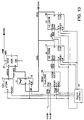
- FIG. 13 a random number generator circuit diagram and a quadrature counter circuit used in accordance with the present invention is shown.
- a program integrated circuit 51 is in communication with a comparator 52 which is further communication with a register 53.
- the quadrature counter circuit portion of the circuit depicted in FIG. 13 is provided to determine at a given position whether the frames are moving the forward direction or the frames are moving in the backward direction.
- the last known position can provide information about the direction of the direction of the given frame at a particular time.
- the voltage is detected by quadrature circuit 56 is in communication with, for example, a 24 bit counter 57 which is communication with a second counter 58.
- Those circuits are in communication with register to receive counted information and interval timer 59 (integrated for convenience).
- the interval timer is set to every 20 msecs. In this manner, the system is able to determine which direction the viewer is going and how far the viewer has come from information provided by the shaft encoder 41 (see FIGS. 6 and 7).
- FIG. 14 three possible frame rate levels are denoted as being represented by parallel horizontal lines.
- the dotted line interwoven among the solid horizontal lines represents the stopping and starting of the user.
- the rotary encoder sends signals to be counted so that the position within the frame sequence can be detected.
- the important points for consideration here are boundary constraints such as the starting point and the ending point, such denoted by position 0 (zero) and position MAX. According to the present invention, by using the counted position, the accidental slipping into the brake zone is avoided.
- the present invention provides a method for determining the position of the viewer in the film sequence by starting at box 61, such being flowcharted in FIG. 15.
- the inquiry as to whether the position is greater than 0 is asked. If the answer is no, then the program asks whether the position is greater than MAX at box 63. If the answer is no, then the system proceeds normal as indicated by box 64. On the other hand, first referring to box 62, if the answer is yes, other conditions are considered.
- the portion of the flow chart depending from a yes answer to box 62 is symmetric to the portion of the flow chart depending from a yes answer to box 63. Therefore, only the portion relating to box 62 will be discussed herein, and the same meaning is applied to the portion relating to box 63.
- the next question is whether the velocity is zero at box 66. If the answer is yes, the program asks whether the last velocity was less than zero at box 67. If the answer is yes, the brake is turned off at box 68. If the answer is yes, the brake is turned on at box 69. On the other hand, if at box 66 the answer was no, then the program sets the velocity to the last velocity at box 71. If that last velocity was less than zero as questioned by box 72, then the brake is turned off at box 73. If the answer to box 72 is no, then the brake is turned on at box 74.
- an amount of braking can be assigned depending upon the speed.
- a certain amount of braking provides advantageous effect. For example, were simulated centrifugal force to provide a haptic response to viewer input, braking is dependent upon content and velocity. In that case, the amount braking is a function of variables which can be programmed into the system.
- the brake is applied in an adaptive manner and is therefore velocity dependent as well as content-dependent. In such a case, feed back generates a speed limit.
- the present invention interactively provides the viewer with a haptic experience based on the content of the prerecorded image data being viewed at a particular moment in time.
Landscapes
- Engineering & Computer Science (AREA)
- General Engineering & Computer Science (AREA)
- Theoretical Computer Science (AREA)
- Multimedia (AREA)
- Physics & Mathematics (AREA)
- General Physics & Mathematics (AREA)
- Human Computer Interaction (AREA)
- User Interface Of Digital Computer (AREA)
- Two-Way Televisions, Distribution Of Moving Picture Or The Like (AREA)
- Image Analysis (AREA)
- Information Retrieval, Db Structures And Fs Structures Therefor (AREA)
- Closed-Circuit Television Systems (AREA)
- Position Input By Displaying (AREA)
Abstract
Description
- The present invention relates to haptic devices and more particularly, to an apparatus and method for providing the viewer of prerecorded visual data a way in which to receive sensory response which is correlated to and dependent on the prerecorded visual data through an input device which the viewer uses to browse the prerecorded visual data.
- As early as the first motion pictures there have been devices which provide viewers of movies the ability to advance the frames of images, thus causing the motion pictures. Originally, crank arms were used to advance the frames. Early motion pictures were typically "hand-cranked" at 16-18 frames per second (fps); today's motion pictures run at 24 or 25 fps; various "special venue" film formats run at 48 and 60 fps; and video runs at 50 or 60 fps. In all cases, the playback fps rate is held constant and equal to the recorded fps rate to convey the sense of real-time motion.
- On the other hand, in the editing process, control over the frame rate is desirable. In editing application, knobs are commonly used as input devices to advance the images to cause the variable frame rate. During the course of movie editing, the editor needs to move back and forth through the film or video material to determine the exact locations in to and out of which to cut, or edit. The his or her better control over this back and forth motion, the more effective the editing process. Such control ranges from hand-cranking film on open reels to sophisticated electronic control for video.
- The use of tactile or haptic feedback is advantageous in video tape recording and editing equipment to provide the user with a "feel" representative of the type of control or operation being effected. Force-feedback circuitry is used to provide the operator with tactile feedback. Force-feedback may be defined as computer-controlled rate of friction or movement of an object. For example, U.S. Patent No. 5,185,561 to Good et al. discloses a torque motor being used as a tactile feedback device. In the case of a rotary knob, force-feedback could occur with an on-off brake, a variable brake, or a motor.
- In video editing systems, two fundamentally different modes of edit control exist: "shuttle" and "jog." A shuttle control is typically a spring-loaded rotary knob which controls frame rate: each unique position of the knob corresponds to a unique frame rate. A jog control is typically a free-turning rotary knob which controls frame position: progressive turning of the knob progressively increments or decrements from one frame to the next. One functional distinction is that a shuttle knob may be held in a non-zero static position and result in a non-zero fps rate while a jog knob must be moving for a non-zero fps rate. In other words, a shuttle is rate-control while jog is position-control.
- Editing, in all cases, in interactive only for the editor. Once the editing is completed, the viewer is a non-interactive recipient of the completed linear program. Other than the ability to vary the frame rate using jog or shuttle controls, currently there is no system or method which provides tactile interactivity between the viewer and the movie.
- In viewing movies while varying the frame rate, it would be advantageous to provide to the viewer haptic responses to his or her input which is dependent on the content of the movie, which may be refereed to as content-dependent, content-based, content-triggered and/or content-driven. For example, the viewer could then experience boundary constraints, textures and hills in combination with speed. While content-dependent tactile response may not be particularly desirable with respect to conventional movies, those movies made for end-user fps control or "browsing" would be well suited to be viewed on a system which was capable of providing content-dependent haptic responses to viewer input.
- The types of movies which are particularly suited to providing content-dependent haptic responses to viewer input include those movies made for surrogate travel, virtual travel, or "moviemaps" [MIT 1978], "browesable movies" [Naimark, Apple 1988], and "navigable movies [Quicktime team, Apple, c1990]. Also, browesable video includes collections of stillframes, such as slide libraries are stored on videotape or disc. Since they are stored as a one-dimensional sequence, they also have no one correct viewing rate, but rather demand user-control for getting from one to another.
- US-A-5 185 561 shows a hand held, one dimensional, torque feedback device that is used to feel and manipulate computer generated visual information and associated torque forces. The device can also be used with a workstation generated display on problems which generate torque.
- The invention is characterized by the subject matter of the independent claims. Further improvements are given by the subject matter of the respective subclaims.
- In contrast to the available systems described above, the present invention provides a system and method for taking into account various aspects of the medium's content, such as edit points and other, boundaries. Moreover, the quality of the "route" through which one "travels," such as rockiness or uphill/downhill grades, are also movie content for which the present invention accounts. According to the present invention, content-dependent data is composed and stored on a data storage device. The content-dependent data can either be manually entered or machine detectable and therefore entered automatically. Herein the term viewer denotes end-user and operator denotes composer of content data and the whole program.
- In setting up the system in the manual context, an operator views the prerecorded image data on a visual data display at either its real-time speed or a slower or faster frame rate. Using commands, the operator, through a content input device, sends content signals to a content data storage device where they are stored for use during a viewer's use of the apparatus.
- When a viewer views the prerecorded image data on the visual data display, the viewer is able to advance the frames by turning, for example a knob, which is the viewer input device. The viewer input device is in communication with a processor which is in turn in communication with the content data storage device.
- According to the present invention, the viewer input device substantially immediately responds to the viewer's input in a haptic manner based on content-dependent data stored in data storage device which corresponds to the prerecorded visual data which is displayed on said visual data display at a particular time.
- Other objects, features and advantages of the invention will become apparent from a reading of the specification, when taken in conjunction with the drawings, in which like reference numerals refer to like elements in the several views.
-
- Figure 1 is a schematic showing some of the features of the present invention;
- Figure 2 depicts a section of film having particular points thereon marked;
- Figure 3 is a blow up of a section of the film of FIG. 2 including frames of footage shot of landscape scenery as one is traveling on a road;
- Figure 4 shows a rotary device located on a scale of positions, wherein "MAX" indicates a braking position and "0" indicates another braking position;
- Figure 5 depicts a braking position such as a "wall" wherein the viewer input device will be stopped and bounced back upon impact;
- Figure 6 depicts a viewer input device in communication with a brake;
- Figure 7 is a blow up of the flex coupling device depicted in FIG. 6;
- Figure 8 is depicts another embodiment of a viewer input device in communication with a brake;
- Figure 9 illustrates the memory device responsible for the brake value depending on whether the rotatory device has reached MAX or 0 as depicted in FIG. 4;
- Figure 10 shows a portion of a DC circuit for turning off and on the brake of the present invention;
- Figure 11 shows a typical pulse width modulation which is capable of signalling the brake to turn off and on;
- Figure 12 shows a quadrature signal configuration used in accordance with the present invention to indicate in which direction the viewer is turning the user input device;
- Figure 13 is a circuit diagram of a circuit providing some functions of the present invention;
- Figure 14 depicts the variation in speed and direction a viewer provides to the system of the present invention through the viewer input device; and
- Figure 15 is a flow chart of a method in which the present invention provides the ability to apply the brake given the variations depicted in FIG. 14.
-
- The present invention includes a system and method for composing content data which is correlated with prerecorded visual data so that it can be played back as a viewer "browses" through the frames. Moreover, the present invention further includes a system and method for providing a viewer with the ability to experience in a haptic manner the content of the video as he or she uses the viewer input device to browse through the frames.
- Turning to FIG. 1, a combined system is shown. That is, the schematic includes both the creation hardware and the play back configuration. These systems are more typically separated into two different systems but are combined in FIG. 1 for economy. In both the creation and the play back systems, the prerecorded medium is viewed on a
display apparatus 11. - In the composition mode, the operator views the apparent motion of the prerecorded image data at a speed which is suitable for composing content data. The content
data input device 12 is of any type such as a key board or mouse and can be in communication with another display device (not shown). As the operator views the prerecorded image data, the operator can determine which of particular content characteristics are applicable to that data. For example, in composing content data, the operator finds edit-points, enters into a software program those points and then enters boundary constraints such as beginning points and end points. - On the other hand, instead of the operator composing the content data by hand and hand entering it into the system, the content data can also be composed by machine. That is, it can automatically be composed. For example, when the footage is being shot, the camera or camera rig can include sensors which sense the texture of a road or the uphill/downhill characteristics of the road. That information can stored on the film stock so that when the film is played back, the content information is retrieved at the same time that the film is played. That information can then be interpreted into braking commands and stored in
content data storage 16. Alternatively, a sophisticated software program can be used to detect certain conditions and characterize those conditions, interpreting them into brake commands which are stored incontent data storage 16. As mentioned above, particular types of footage are well suited in accordance with the present invention. For example, moviemaps, dollies and timelapses are particularly browesable. Moviemaps are distance-triggered sequences (triggered by using an encoder on the wheel of a camera rig and a camera capable of recording single-frames such as one frame every meter) where the camera is pointing in the direction of movement; the effect is "moving forward." Dollies are distance-triggered sequences with a camera pointing sideways where for example, carefully arcing around a sculpture recording one frame per degree of arc provides browseable footages. Timelapses are time-triggered sequences with a stationary camera but where time intervals are exaggerated (such as by recording one frame per minute for 24 hours). - Unlike conventional video, in the above discussed browseable movie applications, there is no one "correct" fps rate with which to view such footage. By providing end-user control, the viewer feels a sense of movement or travel through the visual material. In a moviemap, where the footage taken from a car as the car was moving in the forward direction down a road, the content data could be created so that it is correlated to dips and bumps (i.e., the physical characteristics of the image) the footage has captured as the car advances. In that case, data simulating the texture of the ride in the car is created.
- On the other hand, where the footage taken or simulated from the front of a bicycle which was moving in the forward direction up a hill, the content data could be created so that it is correlated to the effects of gravity on rider as the bicycle advances. In that case, data simulating the pull of gravity on the bicycle is created.
- Moreover, where the footage taken or simulated on a skateboard as it was ridden through a concrete skateboard course. As the skateboard advances up one of the curved walls of the course, it reaches a point where it has lost momentum and therefore can go no farther in that particular direction. The skateboarder would then change direction and head down the same curved wall, continuing in the forward direction. In that case, a boundary constraint has been reached. When the point is reached where the skateboarder can go no farther in a particular direction, data simulating the boundary constraint is created. The boundary constraint in the case of the skateboarder need not be absolute, thus allowing the skateboarder to change direction and head down the same curved wall. When the skateboarder crashes, then the boundary constraint is absolute.
- Referring to FIG. 1, the content data input device is in communication with a
processor 13. (Processor 13 can serve all of the functions described herein or each function can be carried out by individual processors.) The data used to simulate texture, uphills/downhill, boundaries, among other data possibilities, for example, gravity, is translatable into brake control. That is, how a brake in communication with theviewer input device 14 changes the way in which the viewer input device responds to the commands of the viewer. Thus the content data input device has a set of programmed commands such as the magnitude and/or timing of the brake response which are stored in thecontent data storage 16 for retrieval during the viewer's use of the system and method of the present invention. The magnitude and/or timing of the brake response is discussed in detail below. - While the content data is stored in the
content data storage 16, the prerecorded visual data is stored invideo data storage 17. For example, frame sequences can be stored on a single laserdisc as separate disconnected sequences, like tracks on a music CD or chapters in a book. Just as the prerecorded visual data can take any form such as digital or analog, the images can be shot or animated, or can be a combination of both, or can be stills as well. The content data and the prerecorded visual data are correlated and when replayed, are accessed by aprocessor 16 so that they can be experienced by the viewer substantially simultaneously. - The
viewer input device 14 is a rotatory device such as a knob, a "browsewheel," a crank or a trackball. On the other hand, the viewer input device is also a mouse joystick or another suitable input device. When using a knob, browsewheel or crank, a rate-controlled "shuttle" and position-controlled "jog" can be used. - In the viewing mode of the present invention, the user views the prerecorded visual data on
display 11, such being generated by data stored invideo data storage 17 and processed byprocessor 13. While the viewer has control over the frame rate throughviewer input device 14, in accordance with the present invention, theprocessor 13 provides signals to the viewer input device to give the viewer a haptic sensation as the viewer advances through the frames in either the forward or backward directions. - FIG. 2 depicts video or
film footage 19. FIG. 2 though depicting a film strip, is also representative of digital data, stored on a laser disc or the like.Arrows 21 represent time codes or stamps, the number of which corresponds to hours, minutes, seconds or frames. In one application, time codes are interpreted as edit points for use in editing. In accordance with the present invention, time codes are used to correlate video data with content data.Film footage 19 is a prerecorded plurality of frames, distinguishable from generated images which are provided in real-time, such as computer generated images. - Between time codes, there may be several frames. For example, FIG. 3 is a blow up of a
section 22 which contains fourframes 23. These four frames represent landscape in a moviemap, were the footage was taken the car as the car was moving in the forward direction down a road. The content data played in conjunction with the frames is created so that it is correlated to dips and bumps the footage has captured as the car advances. In that case, in advancing the frames through the viewer input device, the viewer senses data simulating the texture of the ride in the car. -
Frame 24a depicts a stop sign far off in the distance whileframes 24b and 24c depict the car approaching the stop sign.Frame 24d depicts the car having reached the stop sign and braking to a stop. In providing feedback signals to the viewer input device based on the content of prerecorded image data, the present invention takes into account that it is preferable to provide the illusion of a mechanical stop. Therefore, the present invention provides the illusion of release without much "stickiness". - FIGS. 4 and 5 both depict the concept of the boundary constraint of a full brake stop. Turning to FIG. 4, a
crank arm 26 is depicted in communication with a ball orcylinder 27. The endshorizontal line 28 represents boundary conditions where for example, "MAX" is equivalent to the full brake stop inframe 24d and "0" is equivalent to the starting position of the car (not shown). In FIG. 5,wall 31 depicts the brake zone.Arrow 32 shows the brake being applied, such being full stop at thebrake zone 31. In a mechanical system, when an object hits the wall, it is stopped in only one direction. However, it has been found that when a full brake, such as particle brake system, there is no motion in the reverse direction because the brake is on, and therefore the system feels unnatural (sticky). It is preferable to induce a sense of release after braking to best capture the feel of a mechanical system. - Turning to FIG. 6, a system of the present invention includes a rotary
shaft coupling device 36 which couples the hand control element such as a crank handle or abrowsewheel 37 to thebrake 38. Theshaft 39 is in communication with a highlyaccurate shaft encoder 41 such as an optical encoder to encode the shaft motion. For example, a shaft encoder providing 5,000 counts per revolutions is preferable. Turning the browsewheel by hand changes the optical encoder output, which is translated by aprocessor 42 to simultaneously change the frame position of the video laserdisc player atbox 43 and change the resistance of the variable brake. Changes in the resistance of the variable brake are dependent on the content of the video material stored on the laserdisc. - As mentioned above, it is preferable to capture the feel of a mechanical system in accordance with the present invention. In so doing, in one embodiment the rotary
shaft coupling device 36 includes aflex coupling device 44 which is blown up in FIG. 7. In this embodiment, the flex coupling provides a minute flexibility in the shaft. With sensors, particular types of motion which are caused by a change in the motion of the shaft rotation are detectable. A different embodiment is depicted in FIG. 8, where the brake is coupled to achain link system 46 havingchain 47. By providing the chain with alittle slack 48, the change in the motion of the shaft is detectable by a small increment. Accordingly, the feeling of a mechanical stop is effected because the system then induces a release when such conditions are sensed. - Alternatively, replacing the brake with a programmable motor provides active self-contained movement by the input device as well as variable resistance, i.e. it turns by itself. For example, the user input device moves on its own if the video material is of moving downhill. Such a replacement further enhances the feeling of tight coupling and control with the image content.
- Turning to FIG. 9, there is shown a
memory 49 for applying different amounts a brake depending upon digital MAX and 0. That is, to induce variable brake values digital inputs are sent to the braking system. Such a circuit configuration is shown in FIG. 10 where in a DC circuit for applying voltage to the brake. Variable braking values are effected by turning "off" and "on" the voltage at different rates. As shown in FIG. 11, by generating a signal having variable pulse-width-modulation, different brake values are possible. However, it has been found that by using a constant pulse, the brake has a tendency to resonate and provides an audible noise. That is the brake acts like a small EM speaker device. - Accordingly, instead of making different pulse width regular pulsetrains to vary the brake value, the present invention includes a pseudo random number generator, a greater-than comparator, and a register. The pseudo random number generator generates numbers out of sequence from 1 to 255. This value is continually compared to a register holding the brake value (0 to 255). For example, using a generator which generates 1 through 255, if one were to set it at 126, there are half high values and half low values, and the output is the average of high to low. By providing a good random distribution of pulses, changing at arbitrary times, there is no period to the noise and therefore there is no resonance.
- Turning to FIG. 13, a random number generator circuit diagram and a quadrature counter circuit used in accordance with the present invention is shown. In the random number generator circuit, a program integrated
circuit 51 is in communication with acomparator 52 which is further communication with aregister 53. - The quadrature counter circuit portion of the circuit depicted in FIG. 13 is provided to determine at a given position whether the frames are moving the forward direction or the frames are moving in the backward direction. Quickly turning to FIG. 12, by offsetting the signals by less than a half period, the last known position can provide information about the direction of the direction of the given frame at a particular time.
- Again referring to FIG. 13, the voltage is detected by
quadrature circuit 56 is in communication with, for example, a 24 bit counter 57 which is communication with asecond counter 58. Those circuits are in communication with register to receive counted information and interval timer 59 (integrated for convenience). Preferably, the interval timer is set to every 20 msecs. In this manner, the system is able to determine which direction the viewer is going and how far the viewer has come from information provided by the shaft encoder 41 (see FIGS. 6 and 7). - In using a system in accordance with the present invention, it is common for a viewer to change the frame rate frequently, providing backtracks and stops. In such situations, it is preferable to provide a manner in which to avoid accidently slipping into a brake zone. Turning to FIG. 14, three possible frame rate levels are denoted as being represented by parallel horizontal lines. The dotted line interwoven among the solid horizontal lines represents the stopping and starting of the user. As discussed above, the rotary encoder sends signals to be counted so that the position within the frame sequence can be detected. The important points for consideration here are boundary constraints such as the starting point and the ending point, such denoted by position 0 (zero) and position MAX. According to the present invention, by using the counted position, the accidental slipping into the brake zone is avoided.
- Referring to the flow chart of FIG. 15, a manner in which to avoid slipping into the brake zone when the user moves to slowly is provided. The present invention provides a method for determining the position of the viewer in the film sequence by starting at
box 61, such being flowcharted in FIG. 15. In thefirst decision box 62, the inquiry as to whether the position is greater than 0 is asked. If the answer is no, then the program asks whether the position is greater than MAX atbox 63. If the answer is no, then the system proceeds normal as indicated bybox 64. On the other hand, first referring tobox 62, if the answer is yes, other conditions are considered. The portion of the flow chart depending from a yes answer tobox 62 is symmetric to the portion of the flow chart depending from a yes answer tobox 63. Therefore, only the portion relating tobox 62 will be discussed herein, and the same meaning is applied to the portion relating tobox 63. - If a position less than zero is detected, the next question is whether the velocity is zero at
box 66. If the answer is yes, the program asks whether the last velocity was less than zero atbox 67. If the answer is yes, the brake is turned off atbox 68. If the answer is yes, the brake is turned on atbox 69. On the other hand, if atbox 66 the answer was no, then the program sets the velocity to the last velocity atbox 71. If that last velocity was less than zero as questioned bybox 72, then the brake is turned off atbox 73. If the answer tobox 72 is no, then the brake is turned on atbox 74. - Another aspect of the present invention, is that according to the present invention, an amount of braking can be assigned depending upon the speed. A certain amount of braking provides advantageous effect. For example, were simulated centrifugal force to provide a haptic response to viewer input, braking is dependent upon content and velocity. In that case, the amount braking is a function of variables which can be programmed into the system.
- Moreover, in the event that the viewer's strength is tested to adapt the viewer input device to a particular user, then the brake is applied in an adaptive manner and is therefore velocity dependent as well as content-dependent. In such a case, feed back generates a speed limit.
- In view of the foregoing, the present invention interactively provides the viewer with a haptic experience based on the content of the prerecorded image data being viewed at a particular moment in time.
Claims (27)
- A system for interactively displaying a plurality of frames of prerecorded visual data, the system incorporating content-based haptic feedback, comprising:means for storing (17) a plurality of frames of the prerecorded visual data; means for generating (12) content data corresponding to a characteristic of the prerecorded visual data;means for storing (16) the content data;means for processing (13) content data to generate a haptic feedback control signal corresponding to the characteristic of the prerecorded visual data;a viewer input device (14) for manually controlling the display on a display device (11) of frames of the prerecorded visual data;means for producing a display control signal in response to operation of the viewer input device; means for generating a haptic feedback force based on the haptic feedback control signal, the haptic feedback force being correlated to the prerecorded visual data being displayed; andmeans for providing the haptic feedback force to the viewer input device.
- A system as in Claim 1, wherein the content data generating means comprises means for manually generating the content data.
- A system as in Claim 1, wherein the content data generating means comprises means for automatically analyzing the prerecorded visual data and generating the content data based upon the analysis.
- A system as in Claim 1, wherein the haptic feedback force generating means comprises a brake.
- A system as in Claim 1, wherein the haptic feedback force generating means comprises a motor.
- A system as in Claim 1, wherein the haptic feedback force providing means comprises:attachment means coupled to the viewer input device such that movement of the viewer input device or a part of the viewer input device corresponds to movement of the attachment means; andmeans for coupling the haptic feedback force generating means to the attachment means.
- A system as in Claim 6, wherein the processing means further comprises a pseudo random number generator for use in generating the haptic feedback control signal.
- A system as in Claim 6, wherein the attachment means comprises a shaft (39), such that movement of the viewer input device or a part of the viewer input device corresponds to rotation of the shaft.
- A system as in Claim 6, wherein the coupling means comprises a flex coupling apparatus (44).
- A system as in Claim 6, wherein the coupling means comprises a slacked chain link apparatus (46).
- A system as in Claim 6, wherein the display control signal producing means comprises an optical encoder (41) in communication with the attachment means.
- A system as in Claim 1, further comprising means for ascertaining the physical strength of a viewer, and wherein the processing means is adapted to produce the haptic feedback control signal in response to the ascertained strength of the viewer.
- A method for interactively displaying a plurality of frames of prerecorded visual data, the method incorporating content-based haptic feedback, comprising the steps of:storing a plurality of frames of the prerecorded visual data; generating content data corresponding to a characteristic of the prerecorded visual data;storing the content data;processing the content data to generate a haptic feedback control signal corresponding to the characteristic of the prerecorded visual data;manually controlling the display on a display device of frames of the prerecorded visual data with a viewer input device;producing a display control signal in response to operation of the viewer input device;generating a haptic feedback force based on the haptic feedback control signal, the haptic feedback force being correlated to the prerecorded visual data being displayed; andproviding the haptic feedback force to the viewer input device.
- A method as in Claim 13, wherein the step of generating content data is performed manually.
- A method as in Claim 13, further comprising the step of ascertaining the physical strength of a viewer, and wherein the step of processing further comprises the step of producing the haptic feedback control signal in response to the ascertained strength of the viewer.
- A method as in Claim 13, wherein the steps of generating and providing the haptic feedback force comprise the step of selectively engaging a brake with a shaft coupled to the viewer input device.
- A method as in Claim 16, wherein the step of selectively engaging the brake comprises the step of using a flex coupling apparatus.
- A method as in Claim 16, wherein the step of selectively engaging the brake comprises the step of using a slacked chain link apparatus.
- A method as in Claim 16, wherein the step of producing a display control signal comprises the step of monitoring the angular position of the shaft and a number of revolutions through which the shaft has advanced.
- Apparatus for controlling a video display (11) generated using pre-recorded video data, comprising:means (14) for enabling a user of the apparatus to provide an instruction to the apparatus regarding generation of the video display;means (13) for communicating with a device used to generate the video display, wherein the means for communicating enables the instruction to be communicated to the device, the device generating the video display in response to the instruction; andmeans for providing a haptic sensation to the user in response to a characteristic of the video data that is used to generate the video display in response to the instruction.
- Apparatus as in Claim 20, wherein the characteristic of the video data relates to the content of an image of the video display generated in response to the instruction.
- Apparatus as in Claim 20, wherein the characteristic of the video data relates to the arrangement of the video data.
- Apparatus as in Claim 22, wherein the characteristic of the video data is a transition between successive video data.
- Apparatus as in Claim 23, wherein the characteristic of the video data is a transition between sliccessive frames of video data.
- Apparatus as in Claim 22, wherein the characteristic of the video data is the beginning or the end of a predetermined sequence of the video data.
- Apparatus as in Claim 20, further comprising means for generating content data based upon the characteristic of the video data, wherein the content data can be communicated to the means for providing a haptic sensation for use in providing the haptic sensation.
- Apparatus as in Claim 20, further comprising a display device for displaying the video display.
Applications Claiming Priority (3)
| Application Number | Priority Date | Filing Date | Title |
|---|---|---|---|
| US29239694A | 1994-08-18 | 1994-08-18 | |
| US292396 | 1994-08-18 | ||
| PCT/US1995/010475 WO1996006392A1 (en) | 1994-08-18 | 1995-08-17 | Content-based haptic input device for video |
Publications (2)
| Publication Number | Publication Date |
|---|---|
| EP0776499A1 EP0776499A1 (en) | 1997-06-04 |
| EP0776499B1 true EP0776499B1 (en) | 2000-02-02 |
Family
ID=23124487
Family Applications (1)
| Application Number | Title | Priority Date | Filing Date |
|---|---|---|---|
| EP95929588A Expired - Lifetime EP0776499B1 (en) | 1994-08-18 | 1995-08-17 | Content-based haptic input device for video |
Country Status (7)
| Country | Link |
|---|---|
| US (2) | US5816823A (en) |
| EP (1) | EP0776499B1 (en) |
| JP (1) | JPH10504920A (en) |
| AT (1) | ATE189539T1 (en) |
| AU (1) | AU3329595A (en) |
| DE (1) | DE69514926T2 (en) |
| WO (1) | WO1996006392A1 (en) |
Families Citing this family (74)
| Publication number | Priority date | Publication date | Assignee | Title |
|---|---|---|---|---|
| US5889670A (en) | 1991-10-24 | 1999-03-30 | Immersion Corporation | Method and apparatus for tactilely responsive user interface |
| US5625576A (en) | 1993-10-01 | 1997-04-29 | Massachusetts Institute Of Technology | Force reflecting haptic interface |
| US20030040361A1 (en) | 1994-09-21 | 2003-02-27 | Craig Thorner | Method and apparatus for generating tactile feedback via relatively low-burden and/or zero burden telemetry |
| US5666138A (en) | 1994-11-22 | 1997-09-09 | Culver; Craig F. | Interface control |
| US6850222B1 (en) | 1995-01-18 | 2005-02-01 | Immersion Corporation | Passive force feedback for computer interface devices |
| US7113166B1 (en) | 1995-06-09 | 2006-09-26 | Immersion Corporation | Force feedback devices using fluid braking |
| US6166723A (en) | 1995-11-17 | 2000-12-26 | Immersion Corporation | Mouse interface device providing force feedback |
| US7973773B2 (en) * | 1995-06-29 | 2011-07-05 | Pryor Timothy R | Multipoint, virtual control, and force based touch screen applications |
| US5825308A (en) | 1996-11-26 | 1998-10-20 | Immersion Human Interface Corporation | Force feedback interface having isotonic and isometric functionality |
| WO1997020305A1 (en) | 1995-11-30 | 1997-06-05 | Virtual Technologies, Inc. | Tactile feedback man-machine interface device |
| US6028593A (en) | 1995-12-01 | 2000-02-22 | Immersion Corporation | Method and apparatus for providing simulated physical interactions within computer generated environments |
| US6161126A (en) | 1995-12-13 | 2000-12-12 | Immersion Corporation | Implementing force feedback over the World Wide Web and other computer networks |
| US6411276B1 (en) | 1996-11-13 | 2002-06-25 | Immersion Corporation | Hybrid control of haptic feedback for host computer and interface device |
| US20080227534A1 (en) * | 1996-11-14 | 2008-09-18 | Bally Gaming, Inc. | Gaming system with savable game states |
| US6758755B2 (en) * | 1996-11-14 | 2004-07-06 | Arcade Planet, Inc. | Prize redemption system for games executed over a wide area network |
| US8235821B2 (en) | 1996-11-14 | 2012-08-07 | Bally Gaming, Inc. | Progressive controller and TCP/IP in gaming system |
| US6686911B1 (en) | 1996-11-26 | 2004-02-03 | Immersion Corporation | Control knob with control modes and force feedback |
| US7489309B2 (en) | 1996-11-26 | 2009-02-10 | Immersion Corporation | Control knob with multiple degrees of freedom and force feedback |
| US6417638B1 (en) * | 1998-07-17 | 2002-07-09 | Sensable Technologies, Inc. | Force reflecting haptic interface |
| US6985133B1 (en) | 1998-07-17 | 2006-01-10 | Sensable Technologies, Inc. | Force reflecting haptic interface |
| US6650338B1 (en) * | 1998-11-24 | 2003-11-18 | Interval Research Corporation | Haptic interaction with video and image data |
| US6529183B1 (en) | 1999-09-13 | 2003-03-04 | Interval Research Corp. | Manual interface combining continuous and discrete capabilities |
| RU2166790C1 (en) * | 2000-05-25 | 2001-05-10 | Курский государственный технический университет | Device for entering image in computer |
| DE10061619A1 (en) * | 2000-12-11 | 2002-06-20 | Bosch Gmbh Robert | operating device |
| KR20020080646A (en) * | 2001-04-17 | 2002-10-26 | 주식회사 핸디정보시스템 | Key signal input device |
| GB2374747A (en) * | 2001-04-19 | 2002-10-23 | Quantel Ltd | An electronic editing system providing tactile feedback to a user |
| US6905733B2 (en) * | 2001-07-24 | 2005-06-14 | University Of Pittsburgh | Irreversible immobilization of enzymes into polyurethane coatings |
| US7623114B2 (en) * | 2001-10-09 | 2009-11-24 | Immersion Corporation | Haptic feedback sensations based on audio output from computer devices |
| US6703550B2 (en) * | 2001-10-10 | 2004-03-09 | Immersion Corporation | Sound data output and manipulation using haptic feedback |
| US7172085B2 (en) * | 2001-12-04 | 2007-02-06 | Beaudette Susan A | Squeezable, fillable feeding device |
| US6748604B2 (en) * | 2002-05-30 | 2004-06-15 | Finger Fitting Products, Inc. | Glove massager |
| US20040040800A1 (en) | 2002-07-31 | 2004-03-04 | George Anastas | System and method for providing passive haptic feedback |
| EP1565889B1 (en) * | 2002-11-25 | 2008-05-14 | Mentorwave Technologies Ltd. | Method and apparatus for virtual walkthrough |
| US7734070B1 (en) | 2002-12-31 | 2010-06-08 | Rajeev Sharma | Method and system for immersing face images into a video sequence |
| US7280095B2 (en) * | 2003-04-30 | 2007-10-09 | Immersion Corporation | Hierarchical methods for generating force feedback effects |
| US7124648B2 (en) * | 2003-05-19 | 2006-10-24 | Alps Electric Co., Ltd. | Force feedback input device |
| RU2256210C2 (en) * | 2003-05-20 | 2005-07-10 | Курский государственный технический университет | Device for inputting image into personal computer |
| US20050062841A1 (en) * | 2003-09-18 | 2005-03-24 | Rivera-Cintron Carlos A. | System and method for multi-media record, distribution and playback using wireless communication |
| US7411576B2 (en) | 2003-10-30 | 2008-08-12 | Sensable Technologies, Inc. | Force reflecting haptic interface |
| KR100581060B1 (en) * | 2003-11-12 | 2006-05-22 | 한국전자통신연구원 | Apparatus and method for synchronizing five senses data, and a system and method for providing multimedia data using the same |
| US7742036B2 (en) | 2003-12-22 | 2010-06-22 | Immersion Corporation | System and method for controlling haptic devices having multiple operational modes |
| US7522152B2 (en) | 2004-05-27 | 2009-04-21 | Immersion Corporation | Products and processes for providing haptic feedback in resistive interface devices |
| RU2267150C1 (en) * | 2004-06-28 | 2005-12-27 | Курский государственный технический университет | Device for making image input into computer |
| US7765333B2 (en) | 2004-07-15 | 2010-07-27 | Immersion Corporation | System and method for ordering haptic effects |
| US7198137B2 (en) | 2004-07-29 | 2007-04-03 | Immersion Corporation | Systems and methods for providing haptic feedback with position sensing |
| US8441433B2 (en) | 2004-08-11 | 2013-05-14 | Immersion Corporation | Systems and methods for providing friction in a haptic feedback device |
| US9495009B2 (en) | 2004-08-20 | 2016-11-15 | Immersion Corporation | Systems and methods for providing haptic effects |
| US8013847B2 (en) | 2004-08-24 | 2011-09-06 | Immersion Corporation | Magnetic actuator for providing haptic feedback |
| US8803796B2 (en) | 2004-08-26 | 2014-08-12 | Immersion Corporation | Products and processes for providing haptic feedback in a user interface |
| US8002089B2 (en) * | 2004-09-10 | 2011-08-23 | Immersion Corporation | Systems and methods for providing a haptic device |
| US9046922B2 (en) | 2004-09-20 | 2015-06-02 | Immersion Corporation | Products and processes for providing multimodal feedback in a user interface device |
| US7764268B2 (en) * | 2004-09-24 | 2010-07-27 | Immersion Corporation | Systems and methods for providing a haptic device |
| WO2006132622A2 (en) * | 2005-06-03 | 2006-12-14 | Nielsen Media Research, Inc. | Methods and apparatus to detect a time-shift event associated with the presentation of media content |
| US20070035665A1 (en) * | 2005-08-12 | 2007-02-15 | Broadcom Corporation | Method and system for communicating lighting effects with additional layering in a video stream |
| US8700791B2 (en) | 2005-10-19 | 2014-04-15 | Immersion Corporation | Synchronization of haptic effect data in a media transport stream |
| US10152124B2 (en) * | 2006-04-06 | 2018-12-11 | Immersion Corporation | Systems and methods for enhanced haptic effects |
| US8378964B2 (en) * | 2006-04-13 | 2013-02-19 | Immersion Corporation | System and method for automatically producing haptic events from a digital audio signal |
| US8000825B2 (en) | 2006-04-13 | 2011-08-16 | Immersion Corporation | System and method for automatically producing haptic events from a digital audio file |
| US7979146B2 (en) | 2006-04-13 | 2011-07-12 | Immersion Corporation | System and method for automatically producing haptic events from a digital audio signal |
| WO2008085487A1 (en) | 2006-12-27 | 2008-07-17 | Immersion Corporation | Virtual detents through vibrotactile feedback |
| KR100860547B1 (en) * | 2007-03-02 | 2008-09-26 | 광주과학기술원 | Tactile information authoring method and apparatus, and computer readable recording medium |
| US8167813B2 (en) * | 2007-05-17 | 2012-05-01 | Immersion Medical, Inc. | Systems and methods for locating a blood vessel |
| JP4811381B2 (en) * | 2007-10-10 | 2011-11-09 | ソニー株式会社 | REPRODUCTION DEVICE, REPRODUCTION METHOD, AND PROGRAM |
| US9019087B2 (en) | 2007-10-16 | 2015-04-28 | Immersion Corporation | Synchronization of haptic effect data in a media stream |
| US8156809B2 (en) | 2008-03-27 | 2012-04-17 | Immersion Corporation | Systems and methods for resonance detection |
| US20100033426A1 (en) * | 2008-08-11 | 2010-02-11 | Immersion Corporation, A Delaware Corporation | Haptic Enabled Gaming Peripheral for a Musical Game |
| US8686951B2 (en) | 2009-03-18 | 2014-04-01 | HJ Laboratories, LLC | Providing an elevated and texturized display in an electronic device |
| US20110199342A1 (en) | 2010-02-16 | 2011-08-18 | Harry Vartanian | Apparatus and method for providing elevated, indented or texturized sensations to an object near a display device or input detection using ultrasound |
| US8540571B2 (en) * | 2010-03-31 | 2013-09-24 | Immersion Corporation | System and method for providing haptic stimulus based on position |
| US9547366B2 (en) | 2013-03-14 | 2017-01-17 | Immersion Corporation | Systems and methods for haptic and gesture-driven paper simulation |
| US9928728B2 (en) | 2014-05-09 | 2018-03-27 | Sony Interactive Entertainment Inc. | Scheme for embedding a control signal in an audio signal using pseudo white noise |
| JP6295342B2 (en) * | 2014-05-09 | 2018-03-14 | 株式会社ソニー・インタラクティブエンタテインメント | Scheme for embedding control signals in audio signals using pseudo white noise |
| US9635440B2 (en) * | 2014-07-07 | 2017-04-25 | Immersion Corporation | Second screen haptics |
| US10832537B2 (en) * | 2018-04-04 | 2020-11-10 | Cirrus Logic, Inc. | Methods and apparatus for outputting a haptic signal to a haptic transducer |
Family Cites Families (18)
| Publication number | Priority date | Publication date | Assignee | Title |
|---|---|---|---|---|
| US4857902A (en) * | 1987-05-14 | 1989-08-15 | Advanced Interaction, Inc. | Position-dependent interactivity system for image display |
| US5270694A (en) * | 1987-05-14 | 1993-12-14 | Advanced Interaction, Inc. | Content addressable video system for image display |
| US5189402A (en) * | 1987-05-14 | 1993-02-23 | Advanced Interaction, Inc. | Content addressable video system for image display |
| US5044956A (en) * | 1989-01-12 | 1991-09-03 | Atari Games Corporation | Control device such as a steering wheel for video vehicle simulator with realistic feedback forces |
| US5229756A (en) * | 1989-02-07 | 1993-07-20 | Yamaha Corporation | Image control apparatus |
| US5184319A (en) * | 1990-02-02 | 1993-02-02 | Kramer James F | Force feedback and textures simulating interface device |
| US5191320A (en) * | 1990-12-15 | 1993-03-02 | Sony Corporation Of America | Variable scale input device |
| JPH05127809A (en) * | 1991-04-19 | 1993-05-25 | Sharp Corp | Three-dimensional spatial coordinate input device |
| ATE181631T1 (en) * | 1991-07-19 | 1999-07-15 | Princeton Video Image Inc | TELEVISION ADS WITH SELECTED CHARACTERS DISPLAYED |
| US5185561A (en) * | 1991-07-23 | 1993-02-09 | Digital Equipment Corporation | Torque motor as a tactile feedback device in a computer system |
| US5189355A (en) * | 1992-04-10 | 1993-02-23 | Ampex Corporation | Interactive rotary controller system with tactile feedback |
| US5320538A (en) * | 1992-09-23 | 1994-06-14 | Hughes Training, Inc. | Interactive aircraft training system and method |
| US5389865A (en) * | 1992-12-02 | 1995-02-14 | Cybernet Systems Corporation | Method and system for providing a tactile virtual reality and manipulator defining an interface device therefor |
| US5495576A (en) * | 1993-01-11 | 1996-02-27 | Ritchey; Kurtis J. | Panoramic image based virtual reality/telepresence audio-visual system and method |
| US5590062A (en) * | 1993-07-02 | 1996-12-31 | Matsushita Electric Industrial Co., Ltd. | Simulator for producing various living environments mainly for visual perception |
| US5734373A (en) * | 1993-07-16 | 1998-03-31 | Immersion Human Interface Corporation | Method and apparatus for controlling force feedback interface systems utilizing a host computer |
| WO1995020787A1 (en) * | 1994-01-27 | 1995-08-03 | Exos, Inc. | Multimode feedback display technology |
| US5580249A (en) * | 1994-02-14 | 1996-12-03 | Sarcos Group | Apparatus for simulating mobility of a human |
-
1995
- 1995-08-17 DE DE69514926T patent/DE69514926T2/en not_active Expired - Fee Related
- 1995-08-17 JP JP8508191A patent/JPH10504920A/en active Pending
- 1995-08-17 EP EP95929588A patent/EP0776499B1/en not_active Expired - Lifetime
- 1995-08-17 WO PCT/US1995/010475 patent/WO1996006392A1/en not_active Ceased
- 1995-08-17 AU AU33295/95A patent/AU3329595A/en not_active Abandoned
- 1995-08-17 AT AT95929588T patent/ATE189539T1/en not_active IP Right Cessation
-
1996
- 1996-10-09 US US08/728,102 patent/US5816823A/en not_active Expired - Lifetime
-
1998
- 1998-10-06 US US09/167,172 patent/US6075967A/en not_active Expired - Lifetime
Also Published As
| Publication number | Publication date |
|---|---|
| JPH10504920A (en) | 1998-05-12 |
| EP0776499A1 (en) | 1997-06-04 |
| WO1996006392A1 (en) | 1996-02-29 |
| DE69514926D1 (en) | 2000-03-09 |
| ATE189539T1 (en) | 2000-02-15 |
| AU3329595A (en) | 1996-03-14 |
| US6075967A (en) | 2000-06-13 |
| DE69514926T2 (en) | 2000-10-05 |
| US5816823A (en) | 1998-10-06 |
Similar Documents
| Publication | Publication Date | Title |
|---|---|---|
| US5816823A (en) | Input device and method for interacting with motion pictures incorporating content-based haptic feedback | |
| US5440348A (en) | Method and user interface for creating, specifying and adjusting motion picture transitions | |
| JP2775127B2 (en) | Video editing operation interface method | |
| US6395969B1 (en) | System and method for artistically integrating music and visual effects | |
| EP1381224A2 (en) | Method and system for display and manipulation of thematic segmentation in the analysis and presentation of film and video | |
| US6807367B1 (en) | Display system enabling dynamic specification of a movie's temporal evolution | |
| US7565059B2 (en) | Dynamic variation of output media signal in response to input media signal | |
| Zollman et al. | Teaching and learning physics with interactive video | |
| EP2587465B1 (en) | Variation and control of sensory work playback | |
| WO1998015112A3 (en) | Dynamic real time exercise video apparatus and method | |
| EP1531474A1 (en) | Video signal playback apparatus and method | |
| JPH04237284A (en) | Video content compression display processing method | |
| GB2527306A (en) | System and method for using eye gaze or head orientation information to create and play interactive movies | |
| JPH0232473A (en) | Moving image retrieving/editing system | |
| CN1089922C (en) | Animation Interface Editing Method | |
| US20050097442A1 (en) | Data processing system and method | |
| CN1229510A (en) | Method and device for keyframe-based video displaying using video cursor frame in multikeyframe screen | |
| JPH06154354A (en) | Training device using stereoscopic image | |
| Dowhal et al. | Producing a video on a technical subject: a guide | |
| US20020154139A1 (en) | Electronic editing system | |
| AU6453300A (en) | Device for interactive and smooth direction control in a compressed digital film and software for managing same | |
| JP2000511736A (en) | Method and apparatus for displaying video based on keyframes using video cursor frames on a multi-keyframe screen | |
| FR2607613A1 (en) | Method and device for servocontrol of the visual display means of a moving vehicle driving simulator | |
| Chominsky | Premiere 6.5 Fundamentals | |
| Adobe Systems | Adobe Premiere 6.5: Classroom in a Book |
Legal Events
| Date | Code | Title | Description |
|---|---|---|---|
| PUAI | Public reference made under article 153(3) epc to a published international application that has entered the european phase |
Free format text: ORIGINAL CODE: 0009012 |
|
| 17P | Request for examination filed |
Effective date: 19970318 |
|
| AK | Designated contracting states |
Kind code of ref document: A1 Designated state(s): AT BE CH DE DK ES FR GB GR IE IT LI LU MC NL PT SE |
|
| AX | Request for extension of the european patent |
Free format text: LT PAYMENT 970318;LV PAYMENT 970318;SI PAYMENT 970318 |
|
| RAX | Requested extension states of the european patent have changed |
Free format text: SI PAYMENT 970318 |
|
| 17Q | First examination report despatched |
Effective date: 19971126 |
|
| GRAG | Despatch of communication of intention to grant |
Free format text: ORIGINAL CODE: EPIDOS AGRA |
|
| GRAG | Despatch of communication of intention to grant |
Free format text: ORIGINAL CODE: EPIDOS AGRA |
|
| GRAH | Despatch of communication of intention to grant a patent |
Free format text: ORIGINAL CODE: EPIDOS IGRA |
|
| GRAH | Despatch of communication of intention to grant a patent |
Free format text: ORIGINAL CODE: EPIDOS IGRA |
|
| GRAA | (expected) grant |
Free format text: ORIGINAL CODE: 0009210 |
|
| AK | Designated contracting states |
Kind code of ref document: B1 Designated state(s): AT BE CH DE DK ES FR GB GR IE IT LI LU MC NL PT SE |
|
| AX | Request for extension of the european patent |
Free format text: SI PAYMENT 19970318 |
|
| PG25 | Lapsed in a contracting state [announced via postgrant information from national office to epo] |
Ref country code: NL Free format text: LAPSE BECAUSE OF FAILURE TO SUBMIT A TRANSLATION OF THE DESCRIPTION OR TO PAY THE FEE WITHIN THE PRESCRIBED TIME-LIMIT Effective date: 20000202 Ref country code: LI Free format text: LAPSE BECAUSE OF FAILURE TO SUBMIT A TRANSLATION OF THE DESCRIPTION OR TO PAY THE FEE WITHIN THE PRESCRIBED TIME-LIMIT Effective date: 20000202 Ref country code: IT Free format text: LAPSE BECAUSE OF FAILURE TO SUBMIT A TRANSLATION OF THE DESCRIPTION OR TO PAY THE FEE WITHIN THE PRESCRIBED TIME-LIMIT;WARNING: LAPSES OF ITALIAN PATENTS WITH EFFECTIVE DATE BEFORE 2007 MAY HAVE OCCURRED AT ANY TIME BEFORE 2007. THE CORRECT EFFECTIVE DATE MAY BE DIFFERENT FROM THE ONE RECORDED. Effective date: 20000202 Ref country code: GR Free format text: LAPSE BECAUSE OF NON-PAYMENT OF DUE FEES Effective date: 20000202 Ref country code: ES Free format text: THE PATENT HAS BEEN ANNULLED BY A DECISION OF A NATIONAL AUTHORITY Effective date: 20000202 Ref country code: CH Free format text: LAPSE BECAUSE OF FAILURE TO SUBMIT A TRANSLATION OF THE DESCRIPTION OR TO PAY THE FEE WITHIN THE PRESCRIBED TIME-LIMIT Effective date: 20000202 Ref country code: BE Free format text: LAPSE BECAUSE OF FAILURE TO SUBMIT A TRANSLATION OF THE DESCRIPTION OR TO PAY THE FEE WITHIN THE PRESCRIBED TIME-LIMIT Effective date: 20000202 Ref country code: AT Free format text: LAPSE BECAUSE OF FAILURE TO SUBMIT A TRANSLATION OF THE DESCRIPTION OR TO PAY THE FEE WITHIN THE PRESCRIBED TIME-LIMIT Effective date: 20000202 |
|
| REF | Corresponds to: |
Ref document number: 189539 Country of ref document: AT Date of ref document: 20000215 Kind code of ref document: T |
|
| REG | Reference to a national code |
Ref country code: CH Ref legal event code: EP |
|
| REF | Corresponds to: |
Ref document number: 69514926 Country of ref document: DE Date of ref document: 20000309 |
|
| PG25 | Lapsed in a contracting state [announced via postgrant information from national office to epo] |
Ref country code: SE Free format text: LAPSE BECAUSE OF FAILURE TO SUBMIT A TRANSLATION OF THE DESCRIPTION OR TO PAY THE FEE WITHIN THE PRESCRIBED TIME-LIMIT Effective date: 20000502 Ref country code: PT Free format text: LAPSE BECAUSE OF FAILURE TO SUBMIT A TRANSLATION OF THE DESCRIPTION OR TO PAY THE FEE WITHIN THE PRESCRIBED TIME-LIMIT Effective date: 20000502 Ref country code: DK Free format text: LAPSE BECAUSE OF FAILURE TO SUBMIT A TRANSLATION OF THE DESCRIPTION OR TO PAY THE FEE WITHIN THE PRESCRIBED TIME-LIMIT Effective date: 20000502 |
|
| REG | Reference to a national code |
Ref country code: IE Ref legal event code: FG4D |
|
| ET | Fr: translation filed | ||
| NLV1 | Nl: lapsed or annulled due to failure to fulfill the requirements of art. 29p and 29m of the patents act | ||
| PG25 | Lapsed in a contracting state [announced via postgrant information from national office to epo] |
Ref country code: LU Free format text: LAPSE BECAUSE OF NON-PAYMENT OF DUE FEES Effective date: 20000817 Ref country code: IE Free format text: LAPSE BECAUSE OF NON-PAYMENT OF DUE FEES Effective date: 20000817 |
|
| PG25 | Lapsed in a contracting state [announced via postgrant information from national office to epo] |
Ref country code: MC Free format text: THE PATENT HAS BEEN ANNULLED BY A DECISION OF A NATIONAL AUTHORITY Effective date: 20000831 |
|
| PLBE | No opposition filed within time limit |
Free format text: ORIGINAL CODE: 0009261 |
|
| STAA | Information on the status of an ep patent application or granted ep patent |
Free format text: STATUS: NO OPPOSITION FILED WITHIN TIME LIMIT |
|
| 26N | No opposition filed | ||
| REG | Reference to a national code |
Ref country code: IE Ref legal event code: MM4A |
|
| REG | Reference to a national code |
Ref country code: GB Ref legal event code: IF02 |
|
| PGFP | Annual fee paid to national office [announced via postgrant information from national office to epo] |
Ref country code: FR Payment date: 20020731 Year of fee payment: 8 |
|
| PGFP | Annual fee paid to national office [announced via postgrant information from national office to epo] |
Ref country code: GB Payment date: 20020814 Year of fee payment: 8 |
|
| PGFP | Annual fee paid to national office [announced via postgrant information from national office to epo] |
Ref country code: DE Payment date: 20020830 Year of fee payment: 8 |
|
| PG25 | Lapsed in a contracting state [announced via postgrant information from national office to epo] |
Ref country code: GB Free format text: LAPSE BECAUSE OF NON-PAYMENT OF DUE FEES Effective date: 20030817 |
|
| PG25 | Lapsed in a contracting state [announced via postgrant information from national office to epo] |
Ref country code: DE Free format text: LAPSE BECAUSE OF NON-PAYMENT OF DUE FEES Effective date: 20040302 |
|
| GBPC | Gb: european patent ceased through non-payment of renewal fee |
Effective date: 20030817 |
|
| PG25 | Lapsed in a contracting state [announced via postgrant information from national office to epo] |
Ref country code: FR Free format text: LAPSE BECAUSE OF NON-PAYMENT OF DUE FEES Effective date: 20040430 |
|
| REG | Reference to a national code |
Ref country code: FR Ref legal event code: ST |