EP0775977A2 - Methods and apparatus for table lookup transformation of digital images - Google Patents
Methods and apparatus for table lookup transformation of digital images Download PDFInfo
- Publication number
- EP0775977A2 EP0775977A2 EP96118888A EP96118888A EP0775977A2 EP 0775977 A2 EP0775977 A2 EP 0775977A2 EP 96118888 A EP96118888 A EP 96118888A EP 96118888 A EP96118888 A EP 96118888A EP 0775977 A2 EP0775977 A2 EP 0775977A2
- Authority
- EP
- European Patent Office
- Prior art keywords
- register
- look
- source
- destination
- registers
- Prior art date
- Legal status (The legal status is an assumption and is not a legal conclusion. Google has not performed a legal analysis and makes no representation as to the accuracy of the status listed.)
- Granted
Links
Images


Classifications
-
- G—PHYSICS
- G06—COMPUTING; CALCULATING OR COUNTING
- G06T—IMAGE DATA PROCESSING OR GENERATION, IN GENERAL
- G06T1/00—General purpose image data processing
- G06T1/60—Memory management
Definitions
- the present invention relates to image processing techniques. More particularly, the invention relates to improved methods and apparatus for performing table lookup transformation of digital images using a digital processor.
- Table lookup is a useful image processing technique for mapping a source image into a destination image.
- the source pixel values of a source image are processed through a lookup table to derive corresponding pixel values in a destination image.
- a source image can be processed via a table lookup to derive a destination image that is darker.
- these pixel values can be mapped via a lookup table into color intensity values for display on a computer display screen.
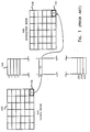
- Fig. 1 illustrates a simple table lookup procedure for transforming a source image into a destination image.
- a source image 102 representing an image stored in the computer's memory, is processed through a lookup table 104 to derive a destination image 106.
- source image 102 is a simple 6 X 6 image, i.e., it comprises 36 discrete source pixels, although a source image of any size may be transformed via the table lookup procedure.
- each source pixel 108 contains a single value, which may represent, for example, the gray scale level of that pixel when rendered on a computer display screen.
- source pixel 108 of Fig. 1 is shown to contain the value 57.
- source image 102 is said to be a 1-banded image.
- a pixel may be represented by more than one value (e.g., 3 values for the red, green, and blue colors of a color pixel).
- Each value contained in source pixel 108 is represented in the computer memory by 8 bits, making source image 102 an 8-bit image.
- Other images may represent their pixels by a fewer or greater number of bits, e.g., 16 bits, to allow for a different range of values.
- Table 104 preferably includes 2 n entries where n represents the number of bits used to represent each value in source pixel 108. Since 8 bits are used in the example of Fig. 1, table 104 therefore has 2 8 or 256 entries.
- the value in each source pixel 108 of source image 102 is passed through table 104 to derive a corresponding value for that pixel in destination image 106, e.g., destination pixel 110.
- the value contained in source pixel 108 is used as an index into table 104.
- the value 57 in source pixel 108 causes the table lookup procedure to look into the 57th entry of table 104 in order to find the corresponding value for destination pixel 110. That value is, for illustration purposes, 15 in Fig. 1.
- source pixel 108 and destination pixel 110 have to be represented by the exact same number of bits. In fact, it is conventional in certain cases to, for example, transform an 8-bit source pixel into a 16-bit destination pixel or vice versa.
- Fig. 2 illustrates a table lookup transformation procedure for a multi-banded source image, i.e., a source image whose pixels contain more than one value.
- each source pixel 208 in source image 202 contains three values, or three bands, 212, 214, and 216.
- Table 204 now is a 3-banded table, i.e., it has three bands.
- table 222 represents band 1 of table 204
- table 224 represents band 2 of table 204
- table 226 represents band 3 of table 204.
- each of tables 222, 224, and 226 therefore has 2 8 or 256 entries.
- each band of source pixel 208 is processed through its associated band of table 204 in order to derive the corresponding band value in destination pixel 210.
- value 52 in band 212 of source pixel 208 is processed by associated band 1 of the table, i.e., table 222, to derive a value 73 to be stored in band 240 of destination pixel 210.
- value 14 in band 242 of destination pixel 210 is derived through band 2 of table 204, i.e., table 224, from the value 60 in band 214 of source pixel 208.
- each band of source pixel 208 is used as the index number into the corresponding band of the table. Note that it is possible in some embodiments for source pixel 208 and destination pixel 210 to have different numbers of bands. For example, source pixel 208 may have three bands while destination pixel may have, for example, five bands.
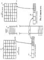
- Fig. 3 shows in more detail the table lookup procedure of Fig. 1.
- the source pixel values are loaded into an integer register 302.
- the values stored into the integer register 302 are then used to select the values from the lookup table and to load them into an integer register 304. Thereafter, the values in integer register will be stored into destination image 106.
- more than one source pixel values may be loaded into integer register 302. These values will be extracted from integer register using logical operations of a conventional nature. More than one value selected from lookup table 104 may be accumulated in integer register 304 before being stored into destination image 106.
- Fig. 4 is a flow chart illustrating the prior art table lookup procedure.
- Fig. 4 starts at step 350.
- the method ascertains whether there are any additional source data, i.e., pixel or band value in the source image, to be processed through the lookup table, e.g., lookup table 104 of Fig. 3. If there is none, the method proceeds to step 354 where the steps of Fig. 4 end.
- additional source data i.e., pixel or band value in the source image
- the method proceeds to step 356 wherein the source data is loaded into an integer register, e.g., register 302 of Fig. 3.
- the pixels are loaded one at a time. If the pixel has more than one band, e.g., three bands as in the case of Fig. 2, all the band values may be loaded together into the integer register in step 356. However, as mentioned earlier, more than one pixel may be loaded into the integer register at once to improve processing efficiency. For example, if the source image is an 8-bit, 1-banded source image (as in the cases of Figs. 1 and 3), up to four pixel values may be loaded into the integer register at once in step 356.
- the source image is an 8-bit, 1-banded source image (as in the cases of Figs. 1 and 3)
- up to four pixel values may be loaded into the integer register at once in step 356.
- step 358 logical operations are employed to separate the pixel/band values that are loaded together in step 356.
- pixel band value denotes either the pixel value if the pixel has only one band or the individual band value if the pixel has more than one band.
- shifting and "AND" operations are performed in order to separate the pixel values for the subsequent table look up.
- Such logical operations are familiar to those skilled in the art.
- the corresponding destination value is obtained from the lookup table.
- the lookup results are then stored into one or more integer registers in step 360.
- the prior art may employ logical operations such as shifting and "OR" to accumulate as many lookup results in the multiple integer registers of step 360 into an accumulation integer register, e.g., integer register 304 of Fig. 3, as possible.
- the accumulation of multiple lookup results into a single accumulation integer register reduces the number of store operations that is performed in a subsequent step 364 of the table.
- step 364 these integer registers are written into the corresponding positions in the destination image. Thereafter, the method returns to step 352 to check whether there is any more source data to process.
- the loading and storing operations typically represent one of the more time-consuming steps of the table lookup transform operation. It is recognized, therefore, that if these steps can be optimized, the lookup transformation that results can be made more efficient. Efficiency is improved by accumulating the lookup values from the lookup table into a register before storing them into the destination image.
- integer registers are used in the post-lookup steps (e.g., steps 362 and 364 of Fig. 4) to accumulate the lookup results.
- the use of integer registers in the post-lookup steps reduces the overall throughput of the table lookup operation because the integer circuitry is, in some processors, slower than other circuits, e.g., the floating point circuitry.
- the improved methods and apparatus preferably improves efficiency by taking advantage of faster circuitries in the processor.
- the invention relates, in one embodiment, to a method in a processor for performing table-lookup transformation through a look-up table a source image having a plurality of source pixels to derive a destination image having a plurality of destination pixels.
- the method includes the step of deriving, for each value in a source pixel of the plurality of source pixels, a look-up result.
- the aforementioned look-up result represents a value in a corresponding destination pixel of the plurality of destination pixels.
- the method further includes the steps of loading a plurality of the look-up results into a plurality of graphics registers in the processor and accumulating the plurality of the look-up results in the plurality of graphics registers into an accumulation register in the processor. Additionally, there is also provided the step of storing the accumulation register into the destination image.
- the invention in another embodiment, relates to computer readable medium containing program instructions for performing table-lookup transformation.
- the table-lookup transformation is performed through a look-up table on a source image having a plurality of source pixels to derive a destination image having a plurality of destination pixels.
- the instructions include instructions for deriving, for each value in a source pixel of the plurality of source pixels, a look-up result, the look-up result representing a value in a corresponding destination pixel of the plurality of destination pixels.
- Fig. 1 illustrates a simple table lookup procedure for transforming a source image into a destination image.
- Fig. 2 illustrates a table lookup procedure for a multi-banded source image, i.e., a source image whose pixels contain more than one value.
- Fig. 3 illustrates in greater detail the lookup procedure for the source image of Fig. 1.
- Fig. 4 is a flow chart illustrating the prior art table lookup procedure.
- Fig. 5 schematically illustrates the table lookup technique in accordance with one embodiment of the present invention.
- Fig. 6 is a flowchart illustrating the steps involved in performing table lookup transformation in accordance with one embodiment of the present invention.
- Fig. 7A is a simple flowchart illustrating, in one embodiment of the invention, the use of the VISTM partial store procedure to store selected values from the accumulation register into the destination image.
- Fig. 7B is a simple flowchart illustrating, in one embodiment of the invention, the use of the VISTM short load instruction for loading source data.
- Fig. 8 is a flowchart illustrating, in one embodiment of the invention, the steps involved in accumulating lookup results employing the VISTM alignaddr and faligndata instructions using variable starting points.
- Fig. 9 is a flowchart illustrating, in one embodiment of the invention, the steps involved in accumulating lookup results employing the VISTM alignaddr and faligndata instructions using a fixed starting point.
- Fig. 10 is a flowchart illustrating, in one embodiment of the invention, the steps involved in accumulating lookup results employing the VISTM fpmerge instruction.
- Fig. 11 schematically illustrates the operation of the fpmerge instruction.
- Fig. 1 illustrates a simple table lookup procedure for transforming a source image into a destination image.
- Fig. 2 illustrates a table lookup procedure for a multi-banded source image, i.e., a source image whose pixels contain more than one value.
- Fig. 3 illustrates in greater detail the lookup procedure for the source image of Fig. 1.
- Fig. 4 is a flow chart illustrating the prior art table lookup procedure.
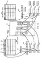
- FIG. 5 schematically illustrates the table lookup operation in accordance with one embodiment of the present invention.
- a source image 502. The pixel values in source image 502 are processed via a lookup table 504 to derive a destination image 506.
- source image 502 is a simple 6 X 4 image (i.e., 24 pixels), as is destination image 506.
- the method applies equally well for source and destination images of any size.
- source pixels 510, 512, 514, and 516 are source pixels 510, 512, 514, and 516.
- Each source pixel in source image 502 has three bands; each band is in turn represented by eight bits of data (i.e., source image 502 is an 8-bit, 3-banded image).
- As many band values in source image 502 are preferably loaded into an integer register as possible to minimize the number of loading operations. In one embodiment, up to 4 band values (8 bits X 4 or 32 bits) are loaded into a 32-bit integer register 518. In another embodiment, up to eight band values from source image 502 are loaded at once into 64-bit long integer register 520. If the processor supports even longer integer registers, these band values in source image 502 may be loaded into those longer integer registers.
- the source pixels are typically loaded row by row.
- the invention works equally well with other methods of loading the source image (e.g., column by column).
- the integer register is preferably filled up with source data during each load operation to minimize the total number of load operations that is performed. If a given load operation loads only a portion of a pixel (e.g., only 2 bands out of 3), the remaining portion may be loaded in the next load cycle or the entire pixel may be reloaded.
- each source pixel of source image 502 contains only three band values
- the loading operation loads four band values to fill up 32-bit integer register 518. These values are shown in Fig. 5 as values 57, 15, 9, and 3, representing pixel 510 and one band of adjacent pixel 512.
- the next load operation could start from value 23 in source pixel 512, in which case the value 3 loaded into 32-bit integer register 518 in the previous load could be temporarily saved in some variable so it does not have to be loaded again.
- loading may begin with band 1 of the next pixel, e.g., loading the value 3 again in the next load operation.
- the band values of source image 502 are loaded into 32-bit integer register 518, 64-bit long integer register 520, or even longer integer registers, the band values therein are processed via logical operations to separate out the pixel/band values. For example, the values 57, 15, and 9 in long integer register 520 are shifted and "ANDed" with an appropriate bit pattern in order to separate out those values into integer registers 522, 524, and 526. As mentioned earlier, the logical operations involved in separating these pixel/band values are familiar to those skilled in the art.
- the band values in integer registers 522, 524, and 526 are then processed via lookup table 504 (through the appropriate band of the table) to derive the lookup results.
- the lookup results are then loaded into double registers 530, 532, and 534.
- double registers are explicitly specified herein as the registers for storing the lookup results and for accumulating them, float registers may well be employed if appropriate. Consequently, float and double may be interchangeably used in the invention since the double registers and the float registers overlap in some processors. e.g., the aforementioned UltraSparcTM processor.
- the ability to utilize the faster circuitry, e.g., the floating point circuitry in this case, in the post-lookup steps represents one major advantage of the present invention.
- the loading of the lookup results from lookup table 504 into double registers 530, 532, and 534 may involve, in some cases, the loading of less than 32 bits (in the case of the example of Fig. 5, 8-bit look-up results) into 32-bit float registers.
- the present invention advantageously employs a short load procedure to facilitate the loading of any byte or short (2 bytes) into a 32-bit float register, a 64-bit double register, or even longer registers.
- the short load instructions furnished by the VISTM instruction set is utilized to perform this short load procedure.
- the UltraSparcTM processor and relevant instructions in the VISTM instruction set are described briefly herein and more completely in United States patent application serial number 08/236,572 by Timothy J. Van Hook, Leslie Dean Kohn, and Robert Yung, filed April 29, 1994 entitled "A Central Processing Unit with Integrated Graphics Functions” (the '572 application), and The SPARC Architecture Manual, Version 9 , (1994) available from SPARC International, Inc. of Menlo Park, California, which are both incorporated by reference herein.
- the lookup results are then accumulated into a 64-bit double register 540.
- a load operation is performed to store the lookup results into the corresponding pixel/band values in destination image 506.
- the destination image may reside in the computer memory, the frame buffer, or the like.
- these accumulation and storing processes take advantage of the faster floating point circuitry on the processor to minimize processing time.
- the present invention provides for an accumulation register, e.g., 64-bit double register 540, that is potentially greater in capacity than the integer register into which the source pixel values are read, e.g., 32-bit integer register 518.
- the fact that the present inventive embodiment provides for multiple load and lookup operations per one 64-bit register store operation means that fewer store operations than the prior art are required in performing the table lookup transformation of source image 502.
- double register 540 has a substantially greater capacity than the 32-bit integer accumulation register, e.g., integer register 304 of Fig. 3, that is employed in the prior art. Therefore, the total number of store operations that is performed in storing the lookup results into the destination image is advantageously reduced.
- registers 530, 532, and 534 as well as accumulation register 540 are employed to store bit patterns, not floating point values.
- the present invention advantageously utilizes the float and double registers as if they are graphic registers.
- the graphics registers are implemented by the float/double registers.
- other 32-bit, 64-bit, or even larger capacity registers may well be employed to minimize the number of store operations that is performed. More importantly, greater efficiency is further achieved if those registers reside in a portion of the processor that is faster than the integer portion, i.e., the portion employed by the prior art to load and accumulate the lookup results.
- accumulation of lookup results requires, in principle, the use of logical operations, e.g., shifting and ORing, to put together lookup results from the multiple float/double registers into a single accumulation float/double register.
- a register data extraction and arrangement (RDEA) procedure is employed to emulate the logical operations.
- Another aspect of this embodiment involves the use of instructions in the VISTM instruction set, such as Alignaddr, Faligndata, and Fpmerge, to implement the register data extraction and arrangement (RDEA) procedure.
- Fig. 6 is a flowchart illustrating the steps involved in performing table lookup transformation in accordance with one embodiment of the present invention.
- Fig. 6 starts at steps 600.
- step 602 the method checks to see whether there is any more source data to process. If not, the method proceeds to step 604 wherein the steps of Fig. 6 end. On the other hand, if there is still source data to process via the table lookup operation, the method proceeds to step 604 wherein the source data is loaded into an integer register.
- the integer register that is used to load the source pixel values is preferably a large integer register (the larger the better to minimize the number of load operations). Further, it is preferable that the integer register of step 604 be filled with as many source pixel values as possible during a load operation.
- step 606 wherein logical operations of a conventional nature, e.g., shifting and "ANDing,” are employed to separate the pixel/band values so that they can be loaded into separate integer registers to facilitate the actual lookup via the lookup table. If the source pixel has multiple bands, the band values are separated in step 606.
- logical operations of a conventional nature e.g., shifting and "ANDing” are employed to separate the pixel/band values so that they can be loaded into separate integer registers to facilitate the actual lookup via the lookup table. If the source pixel has multiple bands, the band values are separated in step 606.
- step 608 the pixel/band values ascertained in step 606 are used to look up the corresponding value from the corresponding band of the table.
- the band values in integer registers 522, 524, and 526 are transformed into corresponding values 63, 92, and 11 from the appropriate band of lookup table 504.
- step 608 the lookup results are loaded into the float/double or even larger registers.
- the programmer typically specifies in step 608, using C, C++ or other programming languages, that the lookup results should be loaded into float/double variables.
- the loading of the lookup results into the float/double registers will then be specified by the compiler.
- the loading of lookup results into float/double registers in step 608 is a major advantage of the present invention because in some processors, e.g., the aforementioned UltraSparcTM processor, the floating point circuitry is much faster than the integer circuitry.
- step 612 the values loaded into the float/double registers (in step 608) are then accumulated into an accumulation float/double register (or even a larger register if such a register is sufficiently fast and is supported by the processor) to facilitate the storing into the destination image.
- 64-bit double registers are used in step 612.
- the method optionally performs as many load operations (step 604) and lookup operations (step 606, 608, and 610), as necessary to fill up the accumulation register in step 612.
- the values in the accumulation registers are stored into the destination image in step 614.
- the inventive method keeps track of how many bits it needs to load in order to fill up a float/double accumulation register for storage. If the load/lookup operations yield extra bits after the accumulation float/double register is filled up, the extra leftover bits may be accumulated in another register to be stored in a subsequent store operation.
- the invention provides, in one embodiment, a short load procedure to facilitate the loading of the short bit patterns (representing the lookup values from the lookup table) into the floating point or double registers.
- the invention provides, in one embodiment, the ability to mask some of the bands.
- the lookup of a 3-banded source image into a 3-banded destination image could be performed in such a way that the second band is masked off, i.e., the values in the second band of the destination image is not changed.
- the partial store procedure is implemented using the VISTM partial store instructions (STDFA).
- STDFA VISTM partial store instructions
- Fig. 7A The use of the VISTM partial store instruction to implement step 614 of Fig. 6 is illustrated in Fig. 7A.
- This class of instructions allow the specification of a mask value, which contains information regarding which bytes from the accumulation register are to be stored into the destination image.
- a mask value which contains information regarding which bytes from the accumulation register are to be stored into the destination image.
- Appendix A For further information regarding the VISTM partial store instructions, reference may be made to, for example, Appendix A. Note that this procedure may also be employed in other situations as well, e.g., in the case when after most of a line of pixels in an image has been processed and there are a few remaining bytes or words to be stored in the destination image. In this case, the partial store procedure is used to store less than a full register of data into memory.
- Fig. 7B illustrates a simple flowchart for implementing the loading step 610 of Fig. 6 in accordance with this embodiment.
- the loading step 610 of Fig. 6 is shown in step 702 to further include the step of utilizing the short load procedure to facilitate look-up result loading into float/double registers.
- VISTM short load instruction ldda The aforementioned short load procedure is implemented, in one embodiment, by the VISTM short load instruction ldda. It should be borne in mind, however, that the use of VISTM instructions is but one way to implement the short load procedure. Reference should be made to Appendix A for a more detailed explanation of the VISTM short load instruction.
- the VISTM short load instruction of Appendix A may be used to, for example, specify that a different number of bits may be loaded (e.g., 16 bits) if the look-up table is 16-bit.
- the byte of interest i.e., the one to be loaded
- the byte of interest can be misaligned in memory.
- the byte of interest does not have to be double-aligned (divisible by 8) in memory.
- the use of the short load procedure allows any byte or word of interest to be directly loaded into the appropriate float/double register.
- the prior art loads data starting from a double-aligned memory location and perform any necessary shifting and logical operations to isolate the data of interest prior to loading. Consequently, the loading operation is made even more efficient under the present invention.
- the VISTM instruction short store of Appendix A may be employed to store a byte or a word into a memory address that is not double-aligned.
- the use of such a short store instruction is particularly useful when there are bytes or words remaining to be stored into the destination image.
- the float/double registers containing the look-up results values are accumulated into an accumulation register to reduce the number of store operations (step 612 of Fig. 6).
- this accumulation operation is performed by shifting and ORing multiple integer registers into a single integer register.
- the present invention also can, in one embodiment, accumulate by emulating the shifting and ORing, albeit using the faster floating point circuitry and the float/double registers.
- the invention advantageously employs align procedures to emulate shifting and ORing operations in accumulating multiple float/double registers into a single accumulation float/double register.
- the VISTM alignaddr and faligndata instructions are used to implement the aforementioned register data extraction and rearrangement procedure.
- An exemplary VIS-related register data extraction and rearrangement procedure is to 1) use the VIS alignaddr instruction to specify an offset, and 2) use the VIS faligndata instruction to concatenate two float/double register and to extract the resulting float/double register from the concatenated string starting from the specified offset.
- the alignaddr and faligndata instructions are used with a variable starting point, i.e., the starting point in the concatenated string from which the resulting data bit pattern in obtained changes depending the double register involved.
- each band represented by 8 bits.
- the pixels band values are stored contiguously in memory.
- the character * denotes the "don't care" bytes.
- the double registers double_3, double_6 and double_9 may be ORed together into another double register before being written into the destination image.
- the aforementioned VISTM instructions alignaddr and faligndata may be used with a fixed starting point,i.e., the starting point in the concatenated string from which the resulting data bit pattern in obtained is fixed.
- a fixed starting point i.e., the starting point in the concatenated string from which the resulting data bit pattern in obtained is fixed.
- each band represented by 8 bits.
- the pixels band values are stored contiguously in memory.
- Eight 8-bit values, representing 8 destination pixels are obtained from the look-up table and loaded into 8 double registers db1, db2, db3, db4, db5, db6, db7, and db8.
- the double register double_accumulator may now be stored into memory.
- the accumulation step 612 of Fig. 6 may also be implemented using a merge procedure.
- the merge procedure two float/double registers are merged together in an interleaved manner into another float/double register.
- multiple float/double registers may be accumulated into an accumulation register for storage.
- Fig. 10 illustrates, in one embodiment of the present invention, the merge procedure utilizing the VISTM fpmerge instruction.
- Two double registers %f4 and %f8 are merged such that their data are interleaved in the resulting double register %f0.
- the VISTM fpmerge instruction is employed to achieve accumulation of multiple float/double registers into a single accumulation float/double register for storage.
- Example 3 Usage of fpmerge to accumulate look-up results for storing into the destination image.
- each band represented by 8 bits.
- the pixel band values are stored contiguously in memory
- eight 8-bit look-up results are obtained from the look-up table and loaded into 8 double registers db1, db2, db3, db4, db5, db6, db7, db8.
- the double register double_accumulator may now be stored into the destination image in memory.
Abstract
Description
- The present invention relates to image processing techniques. More particularly, the invention relates to improved methods and apparatus for performing table lookup transformation of digital images using a digital processor.
- Table lookup is a useful image processing technique for mapping a source image into a destination image. In table lookup transformation, the source pixel values of a source image are processed through a lookup table to derive corresponding pixel values in a destination image. By way of example, a source image can be processed via a table lookup to derive a destination image that is darker. As another example, if the values of the pixels in the source image represent pressure, these pixel values can be mapped via a lookup table into color intensity values for display on a computer display screen.
- Fig. 1 illustrates a simple table lookup procedure for transforming a source image into a destination image. A
source image 102, representing an image stored in the computer's memory, is processed through a lookup table 104 to derive adestination image 106. For ease of illustration,source image 102 is a simple 6X 6 image, i.e., it comprises 36 discrete source pixels, although a source image of any size may be transformed via the table lookup procedure. - In this example, each
source pixel 108 contains a single value, which may represent, for example, the gray scale level of that pixel when rendered on a computer display screen. By way of example,source pixel 108 of Fig. 1 is shown to contain thevalue 57. In the example of Fig. 1, because there is only one value per pixel insource image 102,source image 102 is said to be a 1-banded image. However, a pixel may be represented by more than one value (e.g., 3 values for the red, green, and blue colors of a color pixel). Each value contained insource pixel 108 is represented in the computer memory by 8 bits, makingsource image 102 an 8-bit image. Other images may represent their pixels by a fewer or greater number of bits, e.g., 16 bits, to allow for a different range of values. - Table 104 preferably includes 2n entries where n represents the number of bits used to represent each value in
source pixel 108. Since 8 bits are used in the example of Fig. 1, table 104 therefore has 28 or 256 entries. To perform table lookup transformation, the value in eachsource pixel 108 ofsource image 102 is passed through table 104 to derive a corresponding value for that pixel indestination image 106, e.g.,destination pixel 110. - In the example of Fig. 1, the value contained in
source pixel 108 is used as an index into table 104. By way of example, thevalue 57 insource pixel 108 causes the table lookup procedure to look into the 57th entry of table 104 in order to find the corresponding value fordestination pixel 110. That value is, for illustration purposes, 15 in Fig. 1. - There is no requirement that both
source pixel 108 anddestination pixel 110 have to be represented by the exact same number of bits. In fact, it is conventional in certain cases to, for example, transform an 8-bit source pixel into a 16-bit destination pixel or vice versa. - Fig. 2 illustrates a table lookup transformation procedure for a multi-banded source image, i.e., a source image whose pixels contain more than one value. For illustration purposes, each
source pixel 208 insource image 202 contains three values, or three bands, 212, 214, and 216. Table 204 now is a 3-banded table, i.e., it has three bands. As shown in Fig. 2, table 222 representsband 1 of table 204; table 224 representsband 2 of table 204; and table 226 representsband 3 of table 204. Assuming each band value insource pixel 208 is represented by eight bits of data, each of tables 222, 224, and 226 therefore has 28 or 256 entries. - To perform the lookup, each band of
source pixel 208 is processed through its associated band of table 204 in order to derive the corresponding band value indestination pixel 210. For example, value 52 inband 212 ofsource pixel 208 is processed by associatedband 1 of the table, i.e., table 222, to derive a value 73 to be stored inband 240 ofdestination pixel 210. Likewise,value 14 inband 242 ofdestination pixel 210 is derived throughband 2 of table 204, i.e., table 224, from the value 60 inband 214 ofsource pixel 208. - Similar to the example of Fig. 1, the integer value in each band of
source pixel 208 is used as the index number into the corresponding band of the table. Note that it is possible in some embodiments forsource pixel 208 anddestination pixel 210 to have different numbers of bands. For example,source pixel 208 may have three bands while destination pixel may have, for example, five bands. - Fig. 3 shows in more detail the table lookup procedure of Fig. 1. In Fig. 3, the source pixel values are loaded into an
integer register 302. The values stored into theinteger register 302 are then used to select the values from the lookup table and to load them into aninteger register 304. Thereafter, the values in integer register will be stored intodestination image 106. - To improve efficiency, more than one source pixel values may be loaded into
integer register 302. These values will be extracted from integer register using logical operations of a conventional nature. More than one value selected from lookup table 104 may be accumulated ininteger register 304 before being stored intodestination image 106. - To further illustrate, Fig. 4 is a flow chart illustrating the prior art table lookup procedure. Fig. 4 starts at
step 350. Instep 352, the method ascertains whether there are any additional source data, i.e., pixel or band value in the source image, to be processed through the lookup table, e.g., lookup table 104 of Fig. 3. If there is none, the method proceeds tostep 354 where the steps of Fig. 4 end. - On the other hand, if there is additional source data to be processed, the method proceeds to
step 356 wherein the source data is loaded into an integer register, e.g.,register 302 of Fig. 3. Typically, the pixels are loaded one at a time. If the pixel has more than one band, e.g., three bands as in the case of Fig. 2, all the band values may be loaded together into the integer register instep 356. However, as mentioned earlier, more than one pixel may be loaded into the integer register at once to improve processing efficiency. For example, if the source image is an 8-bit, 1-banded source image (as in the cases of Figs. 1 and 3), up to four pixel values may be loaded into the integer register at once instep 356. - In
step 358, logical operations are employed to separate the pixel/band values that are loaded together instep 356. As the term is used herein pixel band value denotes either the pixel value if the pixel has only one band or the individual band value if the pixel has more than one band. By way of example, if four pixel values are loaded at once into the integer register instep 356, shifting and "AND" operations are performed in order to separate the pixel values for the subsequent table look up. Such logical operations are familiar to those skilled in the art. - For each source pixel/band value, the corresponding destination value is obtained from the lookup table. The lookup results are then stored into one or more integer registers in
step 360. Instep 362, the prior art may employ logical operations such as shifting and "OR" to accumulate as many lookup results in the multiple integer registers ofstep 360 into an accumulation integer register, e.g.,integer register 304 of Fig. 3, as possible. The accumulation of multiple lookup results into a single accumulation integer register reduces the number of store operations that is performed in asubsequent step 364 of the table. - In
step 364, these integer registers are written into the corresponding positions in the destination image. Thereafter, the method returns tostep 352 to check whether there is any more source data to process. - As is known to those skilled in the art, the loading and storing operations (performed in
steps - In the prior art, integer registers are used in the post-lookup steps (e.g.,
steps - In view of the foregoing, what is desired is improved methods and apparatus for optimizing the table lookup procedure. The improved methods and apparatus preferably improves efficiency by taking advantage of faster circuitries in the processor.
- The invention relates, in one embodiment, to a method in a processor for performing table-lookup transformation through a look-up table a source image having a plurality of source pixels to derive a destination image having a plurality of destination pixels. The method includes the step of deriving, for each value in a source pixel of the plurality of source pixels, a look-up result. The aforementioned look-up result represents a value in a corresponding destination pixel of the plurality of destination pixels. The method further includes the steps of loading a plurality of the look-up results into a plurality of graphics registers in the processor and accumulating the plurality of the look-up results in the plurality of graphics registers into an accumulation register in the processor. Additionally, there is also provided the step of storing the accumulation register into the destination image.
- In another embodiment, the invention relates to computer readable medium containing program instructions for performing table-lookup transformation. The table-lookup transformation is performed through a look-up table on a source image having a plurality of source pixels to derive a destination image having a plurality of destination pixels. The instructions include instructions for deriving, for each value in a source pixel of the plurality of source pixels, a look-up result, the look-up result representing a value in a corresponding destination pixel of the plurality of destination pixels. Further, there are provided instructions for loading a plurality of the look-up results into a plurality of graphics registers in the processor and accumulating the plurality of the look-up results in the plurality of graphics registers into an accumulation register in the processor. Still further, there are instructions for storing the accumulation register into the destination image.
- Fig. 1 illustrates a simple table lookup procedure for transforming a source image into a destination image.
- Fig. 2 illustrates a table lookup procedure for a multi-banded source image, i.e., a source image whose pixels contain more than one value.
- Fig. 3 illustrates in greater detail the lookup procedure for the source image of Fig. 1.
- Fig. 4 is a flow chart illustrating the prior art table lookup procedure.
- Fig. 5 schematically illustrates the table lookup technique in accordance with one embodiment of the present invention.
- Fig. 6 is a flowchart illustrating the steps involved in performing table lookup transformation in accordance with one embodiment of the present invention.
- Fig. 7A is a simple flowchart illustrating, in one embodiment of the invention, the use of the VIS™ partial store procedure to store selected values from the accumulation register into the destination image.
- Fig. 7B is a simple flowchart illustrating, in one embodiment of the invention, the use of the VIS™ short load instruction for loading source data.
- Fig. 8 is a flowchart illustrating, in one embodiment of the invention, the steps involved in accumulating lookup results employing the VIS™ alignaddr and faligndata instructions using variable starting points.
- Fig. 9 is a flowchart illustrating, in one embodiment of the invention, the steps involved in accumulating lookup results employing the VIS™ alignaddr and faligndata instructions using a fixed starting point.
- Fig. 10 is a flowchart illustrating, in one embodiment of the invention, the steps involved in accumulating lookup results employing the VIS™ fpmerge instruction.
- Fig. 11 schematically illustrates the operation of the fpmerge instruction.
- Fig. 1 illustrates a simple table lookup procedure for transforming a source image into a destination image. Fig. 2 illustrates a table lookup procedure for a multi-banded source image, i.e., a source image whose pixels contain more than one value. Fig. 3 illustrates in greater detail the lookup procedure for the source image of Fig. 1. Fig. 4 is a flow chart illustrating the prior art table lookup procedure.
- Fig. 5 schematically illustrates the table lookup operation in accordance with one embodiment of the present invention. Referring now to Fig. 5, there is shown a
source image 502. The pixel values insource image 502 are processed via a lookup table 504 to derive adestination image 506. To ease illustration,source image 502 is a simple 6X 4 image (i.e., 24 pixels), as isdestination image 506. However, the method applies equally well for source and destination images of any size. - Within
source image 502, shown aresource pixels source image 502 has three bands; each band is in turn represented by eight bits of data (i.e.,source image 502 is an 8-bit, 3-banded image). As many band values insource image 502 are preferably loaded into an integer register as possible to minimize the number of loading operations. In one embodiment, up to 4 band values (8bits X bit integer register 518. In another embodiment, up to eight band values fromsource image 502 are loaded at once into 64-bitlong integer register 520. If the processor supports even longer integer registers, these band values insource image 502 may be loaded into those longer integer registers. - During the loading of the source pixels, the source pixels are typically loaded row by row. However, the invention works equally well with other methods of loading the source image (e.g., column by column).
- As mentioned earlier, however, the integer register is preferably filled up with source data during each load operation to minimize the total number of load operations that is performed. If a given load operation loads only a portion of a pixel (e.g., only 2 bands out of 3), the remaining portion may be loaded in the next load cycle or the entire pixel may be reloaded.
- For example, although each source pixel of
source image 502 contains only three band values, the loading operation loads four band values to fill up 32-bit integer register 518. These values are shown in Fig. 5 asvalues pixel 510 and one band ofadjacent pixel 512. The next load operation could start fromvalue 23 insource pixel 512, in which case thevalue 3 loaded into 32-bit integer register 518 in the previous load could be temporarily saved in some variable so it does not have to be loaded again. Alternatively, loading may begin withband 1 of the next pixel, e.g., loading thevalue 3 again in the next load operation. - Whether the band values of
source image 502 are loaded into 32-bit integer register 518, 64-bitlong integer register 520, or even longer integer registers, the band values therein are processed via logical operations to separate out the pixel/band values. For example, thevalues long integer register 520 are shifted and "ANDed" with an appropriate bit pattern in order to separate out those values into integer registers 522, 524, and 526. As mentioned earlier, the logical operations involved in separating these pixel/band values are familiar to those skilled in the art. - The band values in integer registers 522, 524, and 526 are then processed via lookup table 504 (through the appropriate band of the table) to derive the lookup results. The lookup results are then loaded into
double registers - It should be noted that the loading of the lookup results from lookup table 504 into
double registers - In one embodiment, the short load instructions furnished by the VIS™ instruction set, manufactured by the aforementioned Sun Microsystems. Inc., is utilized to perform this short load procedure. The UltraSparc™ processor and relevant instructions in the VIS™ instruction set are described briefly herein and more completely in United States patent application serial number 08/236,572 by Timothy J. Van Hook, Leslie Dean Kohn, and Robert Yung, filed April 29, 1994 entitled "A Central Processing Unit with Integrated Graphics Functions" (the '572 application), and The SPARC Architecture Manual,
Version 9, (1994) available from SPARC International, Inc. of Menlo Park, California, which are both incorporated by reference herein. - From
double registers double register 540. Once the lookup results are accumulated in 64-bitdouble register 540, a load operation is performed to store the lookup results into the corresponding pixel/band values indestination image 506. The destination image may reside in the computer memory, the frame buffer, or the like. Here again, these accumulation and storing processes take advantage of the faster floating point circuitry on the processor to minimize processing time. - Optionally, as many load and lookup operations as needed to fill up 64-bit
double register 540 are performed before a store operation intodestination image 506 is performed. Note that the present invention provides for an accumulation register, e.g., 64-bitdouble register 540, that is potentially greater in capacity than the integer register into which the source pixel values are read, e.g., 32-bit integer register 518. The fact that the present inventive embodiment provides for multiple load and lookup operations per one 64-bit register store operation means that fewer store operations than the prior art are required in performing the table lookup transformation ofsource image 502. - Furthermore,
double register 540 has a substantially greater capacity than the 32-bit integer accumulation register, e.g., integer register 304 of Fig. 3, that is employed in the prior art. Therefore, the total number of store operations that is performed in storing the lookup results into the destination image is advantageously reduced. - In the present invention, registers 530, 532, and 534 as well as
accumulation register 540 are employed to store bit patterns, not floating point values. In other words, the present invention advantageously utilizes the float and double registers as if they are graphic registers. Note that in the UltraSparc™ embodiment, the graphics registers are implemented by the float/double registers. In other systems, however, other 32-bit, 64-bit, or even larger capacity registers, may well be employed to minimize the number of store operations that is performed. More importantly, greater efficiency is further achieved if those registers reside in a portion of the processor that is faster than the integer portion, i.e., the portion employed by the prior art to load and accumulate the lookup results. - As mentioned earlier, accumulation of lookup results requires, in principle, the use of logical operations, e.g., shifting and ORing, to put together lookup results from the multiple float/double registers into a single accumulation float/double register. In accordance with one particularly advantageous embodiment of the present invention, a register data extraction and arrangement (RDEA) procedure is employed to emulate the logical operations. Another aspect of this embodiment involves the use of instructions in the VIS™ instruction set, such as Alignaddr, Faligndata, and Fpmerge, to implement the register data extraction and arrangement (RDEA) procedure.
- Fig. 6 is a flowchart illustrating the steps involved in performing table lookup transformation in accordance with one embodiment of the present invention. Fig. 6 starts at
steps 600. Instep 602, the method checks to see whether there is any more source data to process. If not, the method proceeds to step 604 wherein the steps of Fig. 6 end. On the other hand, if there is still source data to process via the table lookup operation, the method proceeds to step 604 wherein the source data is loaded into an integer register. As mentioned in Fig. 5, the integer register that is used to load the source pixel values is preferably a large integer register (the larger the better to minimize the number of load operations). Further, it is preferable that the integer register ofstep 604 be filled with as many source pixel values as possible during a load operation. - From
step 604, the method proceeds to step 606 wherein logical operations of a conventional nature, e.g., shifting and "ANDing," are employed to separate the pixel/band values so that they can be loaded into separate integer registers to facilitate the actual lookup via the lookup table. If the source pixel has multiple bands, the band values are separated instep 606. - In
step 608, the pixel/band values ascertained instep 606 are used to look up the corresponding value from the corresponding band of the table. With reference to Fig. 5, the band values in integer registers 522, 524, and 526 are transformed into correspondingvalues - In
step 608, the lookup results are loaded into the float/double or even larger registers. By way of example, the programmer typically specifies instep 608, using C, C++ or other programming languages, that the lookup results should be loaded into float/double variables. The loading of the lookup results into the float/double registers will then be specified by the compiler. The loading of lookup results into float/double registers instep 608 is a major advantage of the present invention because in some processors, e.g., the aforementioned UltraSparc™ processor, the floating point circuitry is much faster than the integer circuitry. - In
step 612, the values loaded into the float/double registers (in step 608) are then accumulated into an accumulation float/double register (or even a larger register if such a register is sufficiently fast and is supported by the processor) to facilitate the storing into the destination image. In one embodiment, 64-bit double registers are used instep 612. As mentioned earlier, the method optionally performs as many load operations (step 604) and lookup operations (step 606, 608, and 610), as necessary to fill up the accumulation register instep 612. - The values in the accumulation registers, e.g., the float/double registers, are stored into the destination image in
step 614. In one embodiment, the inventive method keeps track of how many bits it needs to load in order to fill up a float/double accumulation register for storage. If the load/lookup operations yield extra bits after the accumulation float/double register is filled up, the extra leftover bits may be accumulated in another register to be stored in a subsequent store operation. These implementation details are conventional and readily understood by those skilled in the art given this disclosure. Fromstep 614, the method returns to step 602 to ascertain again whether there is any more source date to process. - If the look-up results are represented by less than 32 bits, the invention provides, in one embodiment, a short load procedure to facilitate the loading of the short bit patterns (representing the lookup values from the lookup table) into the floating point or double registers.
- In the case of multi-banded source images, the invention provides, in one embodiment, the ability to mask some of the bands. For example, the lookup of a 3-banded source image into a 3-banded destination image could be performed in such a way that the second band is masked off, i.e., the values in the second band of the destination image is not changed.
- This feature is achieved through the use of the partial store procedure. In one specific embodiment, the partial store procedure is implemented using the VIS™ partial store instructions (STDFA). The use of the VIS™ partial store instruction to implement
step 614 of Fig. 6 is illustrated in Fig. 7A. - This class of instructions allow the specification of a mask value, which contains information regarding which bytes from the accumulation register are to be stored into the destination image. For further information regarding the VIS™ partial store instructions, reference may be made to, for example, Appendix A. Note that this procedure may also be employed in other situations as well, e.g., in the case when after most of a line of pixels in an image has been processed and there are a few remaining bytes or words to be stored in the destination image. In this case, the partial store procedure is used to store less than a full register of data into memory.
- Fig. 7B illustrates a simple flowchart for implementing the
loading step 610 of Fig. 6 in accordance with this embodiment. In Fig. 7B, theloading step 610 of Fig. 6 is shown instep 702 to further include the step of utilizing the short load procedure to facilitate look-up result loading into float/double registers. - The aforementioned short load procedure is implemented, in one embodiment, by the VIS™ short load instruction ldda. It should be borne in mind, however, that the use of VIS™ instructions is but one way to implement the short load procedure. Reference should be made to Appendix A for a more detailed explanation of the VIS™ short load instruction.
- As is apparent to those skilled in the art, the VIS™ short load instruction of Appendix A may be used to, for example, specify that a different number of bits may be loaded (e.g., 16 bits) if the look-up table is 16-bit.
- By using the VIS™ short load instruction, the byte of interest, i.e., the one to be loaded, can be misaligned in memory. For example, the byte of interest does not have to be double-aligned (divisible by 8) in memory. The use of the short load procedure allows any byte or word of interest to be directly loaded into the appropriate float/double register. In contrast, the prior art loads data starting from a double-aligned memory location and perform any necessary shifting and logical operations to isolate the data of interest prior to loading. Consequently, the loading operation is made even more efficient under the present invention.
- In an analogous manner, the VIS™ instruction short store of Appendix A may be employed to store a byte or a word into a memory address that is not double-aligned. The use of such a short store instruction is particularly useful when there are bytes or words remaining to be stored into the destination image.
- The float/double registers containing the look-up results values are accumulated into an accumulation register to reduce the number of store operations (step 612 of Fig. 6). In the prior art, this accumulation operation is performed by shifting and ORing multiple integer registers into a single integer register. The present invention also can, in one embodiment, accumulate by emulating the shifting and ORing, albeit using the faster floating point circuitry and the float/double registers. The invention advantageously employs align procedures to emulate shifting and ORing operations in accumulating multiple float/double registers into a single accumulation float/double register.
- In a particularly advantageous embodiment, the VIS™ alignaddr and faligndata instructions are used to implement the aforementioned register data extraction and rearrangement procedure. An exemplary VIS-related register data extraction and rearrangement procedure is to 1) use the VIS alignaddr instruction to specify an offset, and 2) use the VIS faligndata instruction to concatenate two float/double register and to extract the resulting float/double register from the concatenated string starting from the specified offset.
- In the embodiment of Fig. 8 and as illustrated below, the alignaddr and faligndata instructions are used with a variable starting point, i.e., the starting point in the concatenated string from which the resulting data bit pattern in obtained changes depending the double register involved.
- Assume a 3-banded source pixel, each band represented by 8 bits. The pixels band values are stored contiguously in memory. In the examples below, the character * denotes the "don't care" bytes.


- The double registers double_3, double_6 and double_9 may be ORed together into another double register before being written into the destination image.
- Alternatively, the aforementioned VIS™ instructions alignaddr and faligndata may be used with a fixed starting point,i.e., the starting point in the concatenated string from which the resulting data bit pattern in obtained is fixed.. This alternative embodiment is illustrated in Fig. 9 and discussed below.
- Assume 1-banded source image, each band represented by 8 bits. The pixels band values are stored contiguously in memory. Eight 8-bit values, representing 8 destination pixels are obtained from the look-up table and loaded into 8 double registers db1, db2, db3, db4, db5, db6, db7, and db8.

- The following instructions accumulate the above eight 8-bit values from double registers db1-db8 into an accumulation double register double_accumulator to be stored in the proper location in memory.
vis_alignaddr (7,0);
double_accumulator = vis_faligndata (db8, double_accumulator); - The effect of this is:

- The effect of this is:

- The effect of this is:

- The effect of this is:

- The effect of this is:


- The effect of this is:

- The effect of this is:

- The effect of this is:

- The double register double_accumulator may now be stored into memory.
- In accodance with yet another embodiment of the present invention, the
accumulation step 612 of Fig. 6 may also be implemented using a merge procedure. In accordance with the merge procedure, two float/double registers are merged together in an interleaved manner into another float/double register. By taking advantage of the merge procedure, multiple float/double registers may be accumulated into an accumulation register for storage. - Fig. 10 illustrates, in one embodiment of the present invention, the merge procedure utilizing the VIS™ fpmerge instruction. Two double registers %f4 and %f8 are merged such that their data are interleaved in the resulting double register %f0.
- In the embodiment of Fig. 10 and as illustrated below, the VIS™ fpmerge instruction is employed to achieve accumulation of multiple float/double registers into a single accumulation float/double register for storage.
- Assume a 1-banded source image, each band represented by 8 bits. The pixel band values are stored contiguously in memory
- In this example, eight 8-bit look-up results are obtained from the look-up table and loaded into 8 double registers db1, db2, db3, db4, db5, db6, db7, db8.

- The following instructions accumulate the eight 8-bit look-up results into the double register double_accumulator:


- The double register double_accumulator may now be stored into the destination image in memory.
- While this invention has been described in terms of several preferred embodiments, there are alterations, permutations, and equivalents which fall within the scope of this invention. It should also be noted that there are may alternative ways of implementing the methods and apparatuses of the present invention. It is therefore intended that the following appended claims be interpreted as including all such alterations, permutations, and equivalents as fall within the true spirit and scope of the present invention.


Claims (17)
- A method in a processor for performing table-lookup transformation, through a look-up table, a source image having a plurality of source pixels to derive a destination image having a plurality of destination pixels, comprising the steps of:deriving, for each value in a source pixel of said plurality of source pixels, a look-up result, said look-up result representing a value in a corresponding destination pixel of said plurality of destination pixels;loading a plurality of said look-up results into a plurality of graphics registers in said processor;accumulating said plurality of said look-up results in said plurality of graphics registers into an accumulation register in said processor; andstoring said accumulation register into said destination image.
- The method of claim 1 wherein said accumulation register is a 32-bit float register.
- The method of claim 1 wherein said accumulation register is a 64-bit double register.
- The method of claim 1 wherein said graphics registers and said accumulation register are 64-bit double registers.
- The method of claim 1 wherein said loading step comprises the step of utilizing a short load procedure to load a bit pattern having fewer bits than the number of bits in said graphics registers into one of said graphics registers, said bit pattern representing one of said look-up results.
- The method of claim 1 wherein said loading step comprises the step of utilizing a short load procedure to load a bit pattern that is misaligned in memory into one of said graphics registers, said bit pattern representing one of said look-up results.
- The method of claim 1 wherein said accumulating step comprises the step of utilizing a register data extraction and rearrangement procedure to accumulate said look-up results in said graphics registers into said accumulation register.
- The method of claim 7 wherein said register data extraction and rearrangement procedure is used with variable starting points.
- The method of claim 7 wherein said register data extraction and rearrangement procedure is used with a fixed starting point.
- The method of claim 7 wherein said register data extraction and rearrangement procedure is implemented by a merge procedure.
- The method of claim 1 wherein storing step comprises the step of utilizing a partial store procedure to store selective bits of said accumulation register into said destination image.
- A computer readable medium containing program instructions for performing table-lookup transformation through a look-up table a source image having a plurality of source pixels to derive a destination image having a plurality of destination pixels, said instructions performing the steps of:deriving, for each value in a source pixel of said plurality of source pixels, a look-up result, said look-up result representing a value in a corresponding destination pixel of said plurality of destination pixels;loading a plurality of said look-up results into a plurality of graphics registers in said processor;accumulating said plurality of said look-up results in said plurality of graphics registers into an accumulation register in said processor; andstoring said accumulation register into said destination image.
- The computer readable medium of claim 12 wherein said accumulation register is a 64-bit double register.
- The computer readable medium of claim 12 wherein said accumulating step comprises the step of utilizing a register data extraction and rearrangement procedure to accumulate said look-up results in said graphics registers into said accumulation register.
- The computer readable medium of claim 14 wherein said register data extraction and rearrangement procedure is used with variable starting points.
- The computer readable medium of claim 14 wherein said register data extraction and rearrangement procedure is used with a fixed starting point.
- The computer readable medium of claim 14 wherein said register data extraction and rearrangement procedure is implemented by a merge procedure.
Applications Claiming Priority (2)
| Application Number | Priority Date | Filing Date | Title |
|---|---|---|---|
| US562673 | 1983-12-19 | ||
| US08/562,673 US5802219A (en) | 1995-11-27 | 1995-11-27 | Methods and apparatus for table lookup transformation of digital images |
Publications (3)
| Publication Number | Publication Date |
|---|---|
| EP0775977A2 true EP0775977A2 (en) | 1997-05-28 |
| EP0775977A3 EP0775977A3 (en) | 1999-03-10 |
| EP0775977B1 EP0775977B1 (en) | 2003-10-01 |
Family
ID=24247275
Family Applications (1)
| Application Number | Title | Priority Date | Filing Date |
|---|---|---|---|
| EP96118888A Expired - Lifetime EP0775977B1 (en) | 1995-11-27 | 1996-11-25 | Table lookup transformation of digital images |
Country Status (3)
| Country | Link |
|---|---|
| US (1) | US5802219A (en) |
| EP (1) | EP0775977B1 (en) |
| JP (1) | JPH1027241A (en) |
Cited By (1)
| Publication number | Priority date | Publication date | Assignee | Title |
|---|---|---|---|---|
| GB2409061A (en) * | 2003-12-09 | 2005-06-15 | Advanced Risc Mach Ltd | Table lookup operation for indexing data stored in registers |
Families Citing this family (15)
| Publication number | Priority date | Publication date | Assignee | Title |
|---|---|---|---|---|
| US5953021A (en) * | 1997-05-22 | 1999-09-14 | Sun Microsystems, Inc. | Microprocessor system for data channel extraction |
| US5886712A (en) * | 1997-05-23 | 1999-03-23 | Sun Microsystems, Inc. | Data channel extraction in a microprocessor |
| JP3904162B2 (en) * | 1997-05-29 | 2007-04-11 | 富士フイルム株式会社 | Auto setup processing method |
| US6263426B1 (en) | 1998-04-30 | 2001-07-17 | Intel Corporation | Conversion from packed floating point data to packed 8-bit integer data in different architectural registers |
| US6282554B1 (en) | 1998-04-30 | 2001-08-28 | Intel Corporation | Method and apparatus for floating point operations and format conversion operations |
| US6266769B1 (en) | 1998-04-30 | 2001-07-24 | Intel Corporation | Conversion between packed floating point data and packed 32-bit integer data in different architectural registers |
| US6247116B1 (en) | 1998-04-30 | 2001-06-12 | Intel Corporation | Conversion from packed floating point data to packed 16-bit integer data in different architectural registers |
| US5995122A (en) * | 1998-04-30 | 1999-11-30 | Intel Corporation | Method and apparatus for parallel conversion of color values from a single precision floating point format to an integer format |
| US6292815B1 (en) | 1998-04-30 | 2001-09-18 | Intel Corporation | Data conversion between floating point packed format and integer scalar format |
| US6762791B1 (en) * | 1999-02-16 | 2004-07-13 | Robert W. Schuetzle | Method for processing digital images |
| US7168051B2 (en) * | 2000-10-10 | 2007-01-23 | Addnclick, Inc. | System and method to configure and provide a network-enabled three-dimensional computing environment |
| US6621498B1 (en) | 2000-11-01 | 2003-09-16 | Xerox Corporation | High-speed non-separable color table lookup |
| US6766051B2 (en) * | 2000-12-06 | 2004-07-20 | Xerox Corporation | Adaptive tree-base lookup for non-separably divided color tables |
| GB2399900B (en) * | 2003-03-27 | 2005-10-05 | Micron Technology Inc | Data reording processor and method for use in an active memory device |
| US10095479B2 (en) * | 2015-04-23 | 2018-10-09 | Google Llc | Virtual image processor instruction set architecture (ISA) and memory model and exemplary target hardware having a two-dimensional shift array structure |
Family Cites Families (8)
| Publication number | Priority date | Publication date | Assignee | Title |
|---|---|---|---|---|
| US4751446A (en) * | 1985-12-06 | 1988-06-14 | Apollo Computer, Inc. | Lookup table initialization |
| US4933878A (en) * | 1988-07-07 | 1990-06-12 | Texas Instruments Incorporated | Graphics data processing apparatus having non-linear saturating operations on multibit color data |
| US4799053A (en) * | 1986-04-28 | 1989-01-17 | Texas Instruments Incorporated | Color palette having multiplexed color look up table loading |
| US4839801A (en) * | 1986-11-03 | 1989-06-13 | Saxpy Computer Corporation | Architecture for block processing computer system |
| EP0303752B1 (en) * | 1987-08-20 | 1993-06-02 | International Business Machines Corporation | Memory access control device in a mixed data format system |
| US5157388A (en) * | 1989-02-14 | 1992-10-20 | Intel Corporation | Method and apparatus for graphics data interpolation |
| US5204958A (en) * | 1991-06-27 | 1993-04-20 | Digital Equipment Corporation | System and method for efficiently indexing and storing a large database with high data insertion frequency |
| US5487022A (en) * | 1994-03-08 | 1996-01-23 | Texas Instruments Incorporated | Normalization method for floating point numbers |
-
1995
- 1995-11-27 US US08/562,673 patent/US5802219A/en not_active Expired - Lifetime
-
1996
- 1996-11-25 EP EP96118888A patent/EP0775977B1/en not_active Expired - Lifetime
- 1996-11-26 JP JP8353404A patent/JPH1027241A/en active Pending
Non-Patent Citations (1)
| Title |
|---|
| "The SPARC Architecture Manual", vol. 9, 1994, SPARC INTERNATION INC., MENLO PARK, CA |
Cited By (3)
| Publication number | Priority date | Publication date | Assignee | Title |
|---|---|---|---|---|
| GB2409061A (en) * | 2003-12-09 | 2005-06-15 | Advanced Risc Mach Ltd | Table lookup operation for indexing data stored in registers |
| US6958718B2 (en) | 2003-12-09 | 2005-10-25 | Arm Limited | Table lookup operation within a data processing system |
| GB2409061B (en) * | 2003-12-09 | 2006-09-13 | Advanced Risc Mach Ltd | Table lookup operation within a data processing system |
Also Published As
| Publication number | Publication date |
|---|---|
| EP0775977B1 (en) | 2003-10-01 |
| US5802219A (en) | 1998-09-01 |
| JPH1027241A (en) | 1998-01-27 |
| EP0775977A3 (en) | 1999-03-10 |
Similar Documents
| Publication | Publication Date | Title |
|---|---|---|
| EP0775977A2 (en) | Methods and apparatus for table lookup transformation of digital images | |
| US4718024A (en) | Graphics data processing apparatus for graphic image operations upon data of independently selectable pitch | |
| CA2282409C (en) | Instruction compression and decompression system and method for a processor | |
| US6825847B1 (en) | System and method for real-time compression of pixel colors | |
| US5241658A (en) | Apparatus for storing information in and deriving information from a frame buffer | |
| US5550972A (en) | Method and apparatus for efficient transfer of data to memory | |
| US6492992B2 (en) | Graphic pattern processing apparatus | |
| US5931940A (en) | Testing and string instructions for data stored on memory byte boundaries in a word oriented machine | |
| EP0149120A2 (en) | A method for expansion of a digital image | |
| US5867145A (en) | Graphical image recasting | |
| JP2792625B2 (en) | Apparatus for displaying video image on display screen by line and point frame sweep | |
| US5522082A (en) | Graphics display processor, a graphics display system and a method of processing graphics data with control signals connected to a central processing unit and graphics circuits | |
| US5077678A (en) | Graphics data processor with window checking for determining whether a point is within a window | |
| US6388586B1 (en) | Method for reversing the bits of a computer data structure | |
| US5694490A (en) | System and method for a simultaneous multi-band block-stop filter | |
| US5946222A (en) | Method and apparatus for performing a masked byte addition operation | |
| US5294918A (en) | Graphics processing apparatus having color expand operation for drawing color graphics from monochrome data | |
| JP3201716B2 (en) | Computer equipment | |
| US8135229B1 (en) | Image processing method and device | |
| EP1125193A1 (en) | Variable-instruction-length processing | |
| US6396504B1 (en) | Graphical image data reformatting method and apparatus | |
| US8494288B2 (en) | Methods for digital image compression | |
| US5953021A (en) | Microprocessor system for data channel extraction | |
| US6754395B1 (en) | Image information encoding method and decoding method | |
| US5886712A (en) | Data channel extraction in a microprocessor |
Legal Events
| Date | Code | Title | Description |
|---|---|---|---|
| PUAI | Public reference made under article 153(3) epc to a published international application that has entered the european phase |
Free format text: ORIGINAL CODE: 0009012 |
|
| AK | Designated contracting states |
Kind code of ref document: A2 Designated state(s): GB SE |
|
| PUAL | Search report despatched |
Free format text: ORIGINAL CODE: 0009013 |
|
| AK | Designated contracting states |
Kind code of ref document: A3 Designated state(s): GB SE |
|
| 17P | Request for examination filed |
Effective date: 19990910 |
|
| 17Q | First examination report despatched |
Effective date: 20020624 |
|
| GRAH | Despatch of communication of intention to grant a patent |
Free format text: ORIGINAL CODE: EPIDOS IGRA |
|
| RTI1 | Title (correction) |
Free format text: TABLE LOOKUP TRANSFORMATION OF DIGITAL IMAGES |
|
| GRAS | Grant fee paid |
Free format text: ORIGINAL CODE: EPIDOSNIGR3 |
|
| GRAA | (expected) grant |
Free format text: ORIGINAL CODE: 0009210 |
|
| AK | Designated contracting states |
Kind code of ref document: B1 Designated state(s): GB SE |
|
| REG | Reference to a national code |
Ref country code: GB Ref legal event code: FG4D |
|
| PG25 | Lapsed in a contracting state [announced via postgrant information from national office to epo] |
Ref country code: SE Free format text: LAPSE BECAUSE OF FAILURE TO SUBMIT A TRANSLATION OF THE DESCRIPTION OR TO PAY THE FEE WITHIN THE PRESCRIBED TIME-LIMIT Effective date: 20040101 |
|
| PLBE | No opposition filed within time limit |
Free format text: ORIGINAL CODE: 0009261 |
|
| STAA | Information on the status of an ep patent application or granted ep patent |
Free format text: STATUS: NO OPPOSITION FILED WITHIN TIME LIMIT |
|
| 26N | No opposition filed |
Effective date: 20040702 |
|
| PGFP | Annual fee paid to national office [announced via postgrant information from national office to epo] |
Ref country code: GB Payment date: 20151125 Year of fee payment: 20 |
|
| REG | Reference to a national code |
Ref country code: GB Ref legal event code: PE20 Expiry date: 20161124 |
|
| PG25 | Lapsed in a contracting state [announced via postgrant information from national office to epo] |
Ref country code: GB Free format text: LAPSE BECAUSE OF EXPIRATION OF PROTECTION Effective date: 20161124 |