EP0775859A1 - Mechanical seal for a compressor and centrifugal compressor comprising the mechanical seal - Google Patents
Mechanical seal for a compressor and centrifugal compressor comprising the mechanical seal Download PDFInfo
- Publication number
- EP0775859A1 EP0775859A1 EP96118394A EP96118394A EP0775859A1 EP 0775859 A1 EP0775859 A1 EP 0775859A1 EP 96118394 A EP96118394 A EP 96118394A EP 96118394 A EP96118394 A EP 96118394A EP 0775859 A1 EP0775859 A1 EP 0775859A1
- Authority
- EP
- European Patent Office
- Prior art keywords
- slide member
- mechanical seal
- rotating
- rotating slide
- support member
- Prior art date
- Legal status (The legal status is an assumption and is not a legal conclusion. Google has not performed a legal analysis and makes no representation as to the accuracy of the status listed.)
- Granted
Links
- 230000002093 peripheral effect Effects 0.000 claims abstract description 9
- 239000000463 material Substances 0.000 claims abstract description 7
- HBMJWWWQQXIZIP-UHFFFAOYSA-N silicon carbide Chemical compound [Si+]#[C-] HBMJWWWQQXIZIP-UHFFFAOYSA-N 0.000 claims description 9
- 229910010271 silicon carbide Inorganic materials 0.000 claims description 9
- 238000006073 displacement reaction Methods 0.000 abstract description 5
- 238000010276 construction Methods 0.000 description 4
- 239000007789 gas Substances 0.000 description 3
- RWSOTUBLDIXVET-UHFFFAOYSA-N Dihydrogen sulfide Chemical compound S RWSOTUBLDIXVET-UHFFFAOYSA-N 0.000 description 2
- 239000000919 ceramic Substances 0.000 description 2
- 230000007797 corrosion Effects 0.000 description 2
- 238000005260 corrosion Methods 0.000 description 2
- 239000012530 fluid Substances 0.000 description 2
- 229910000037 hydrogen sulfide Inorganic materials 0.000 description 2
- 238000004519 manufacturing process Methods 0.000 description 2
- 238000001816 cooling Methods 0.000 description 1
- 230000000694 effects Effects 0.000 description 1
- 238000009434 installation Methods 0.000 description 1
- 238000007789 sealing Methods 0.000 description 1
- 229910001220 stainless steel Inorganic materials 0.000 description 1
- 239000010935 stainless steel Substances 0.000 description 1
Images

Classifications
-
- F—MECHANICAL ENGINEERING; LIGHTING; HEATING; WEAPONS; BLASTING
- F16—ENGINEERING ELEMENTS AND UNITS; GENERAL MEASURES FOR PRODUCING AND MAINTAINING EFFECTIVE FUNCTIONING OF MACHINES OR INSTALLATIONS; THERMAL INSULATION IN GENERAL
- F16J—PISTONS; CYLINDERS; SEALINGS
- F16J15/00—Sealings
- F16J15/16—Sealings between relatively-moving surfaces
- F16J15/34—Sealings between relatively-moving surfaces with slip-ring pressed against a more or less radial face on one member
- F16J15/3464—Mounting of the seal
- F16J15/3468—Means for controlling the deformations of the contacting faces
-
- F—MECHANICAL ENGINEERING; LIGHTING; HEATING; WEAPONS; BLASTING
- F04—POSITIVE - DISPLACEMENT MACHINES FOR LIQUIDS; PUMPS FOR LIQUIDS OR ELASTIC FLUIDS
- F04D—NON-POSITIVE-DISPLACEMENT PUMPS
- F04D29/00—Details, component parts, or accessories
- F04D29/08—Sealings
- F04D29/10—Shaft sealings
- F04D29/12—Shaft sealings using sealing-rings
- F04D29/122—Shaft sealings using sealing-rings especially adapted for elastic fluid pumps
Definitions
- the present invention relates to a mechanical seal for a compressor and to a centrifugal compressor comprising the mechanical seal.
- FIG. 7 shows the cross-sectional view of the main part of the conventional mechanical seal.
- Two annular rotating slide members 33 are attached to an annular support member 32 by shrinkage.
- the outer end surface 36 of each slide member 33 forms a sliding surface which contacts an opposed stationary slide member 34 exerting an appropriate pressure on the rotating slide member 33.
- the rotating slide member 33 and the stationary slide member 34 prevent fluid from leaking out of a centrifugal compressor at the sliding area.
- the outer diameter of the rotating slide member 33 is constant.
- the stiffness of the materials of both slide members are to be taken in consideration.
- the slide members are required to have low friction at the slide surfaces thereof. Because a corrosive gas such as hydrogen sulfide is often dealt with, the slide members have to be resistant against corrosion. Finally the wear has to be small so that the slide members can be used for a period of at least 2 to 3 consecutive years.
- SiC silicon carbide
- silicon carbide is a brittle material so that when an excessive load is applied to the slide members, cracks may occur at the surface of the slide members.
- the shrinkage stress becomes greater when the centrifugal compressor is operated at a higher speed. As the maximum shrinkage fitting load may not exceed a certain value, the shrinkage fitting load for installation has to be below a proper value.
- an axially displacement or falling out of the rotating slide member 33 may occur due to a lack of supporting force when an impact force is applied to the centrifugal compressor from outside during operation or installing thereof.
- centrifugal compressor with a high speed and a high reliability seal is to be provided.
- Advantegeously at least one of the edges of the fitting portion is rounded.
- the outer diameter of the bottom of the peripheral recess is preferably smaller than the outer diameter of the rest of the periphery by 0.01-0.1 mm and/or the rounded edge of the fitting portion preferably has a radius of curvature of 0.05-0.2mm.
- said rotating slide member has an increased heat transfer area.
- said rotating slide member is made of silicon carbide.
- the mechanical seal of the present invention has a high reliabilty and a simple construction. Therefore it is easy to manufacture.
- a centrifugal compressor operated at a rated rotational speed of 5000-2000 rpm and a seal pressure of 0.52 MPa and including a rotating shaft having an outer diameter of 100 - 200 mm preferably comprises a mechanical seal of the present invention to have a high reliability.
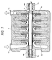
- the multistage centrifugal compressor shown in Fig. 1 comprises a casing 1 in which a rotary shaft 2 is rotably supported by means of bearings 7a, 7b.
- a suction port 4 and a discharge port 5 are provided in the casing 1 .
- Between the suction port 4 and the discharge port 5 several impellers 3 are attached to the rotary shaft 2 for rotating therewith.
- a mechanical seal 6a is provided between the outermost impeller 3a on the suction side and the corresponding bearing 7a preventing the leakage of fluid from the interior of the casing 1 to the exterior through the space between the shaft 2 and the casing 1.
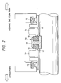
- the overall construction of the mechanical seal is shown by means of mechanical seal 6a in Fig. 2.
- the mechanical seal 6a comprises two annular rotating slide members 13 which are attached to the rotating shaft 2 by means of a rotating support member 12 which is fixed to the shaft 2.
- the rotating slide members 13 and the support member 12 rotate together with the shaft 2.
- the mechanical seal 6a further comprises stationary slide members 14 which exert an appropriate pressure to the opposed end surface of the corresponding rotating slide member 13 by means of a spring 15. Therefore gas inside the compressor is prevented from leaking to the exterior of the compressor at the sliding region 17 at which the rotating slide members 13 contact the corresponding stationary slide member 14.
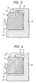
- Fig. 3 shows a detail of a mechanical seal for the use in a centrifugal compressor with a rated rotational speed of 5000-20000 rpm, a shaft power of 300-8000 kW, a shaft diameter of 100-200 mm and a seal pressure 0.5-2 MPa.
- An example of a appropriate centrifugal compressor has a rated rotational speed of 9990 rpm, a shaft power of 6670 kW, a shaft diameter of 140 mm at the seal location and a seal pressure of 0.7 MPa.
- the rotating slide member 13 preferably consists of hard materials such as SiC (silicon carbide). Therefore, the friction at the slide surface 16 is low, corrosion resistance against corrosive gas, such as hydrogen sulfide, is excellent, and the wear is small, so that the seal can be used at least 2 to 3 consecutive years.
- SiC silicon carbide
- the support member 12 consists of stainless steel.
- the support member 12 comprises an inner ring element 20 which is fixed to the shaft 2 by shrinkage and a coaxial outer ring 21.
- the inner ring element 20 and the outer ring element 21 are connected by a radially extending web 22.
- a radially inwardly extending fitting portion 23 runs along the inner periphery of the outer ring 21.
- the fitting portion 23 comprises a cylindrical end surface 24 extending between radially extending side surfaces 25, 26.
- the rotating slide member 13 is arranged between the fitting portion 23 and the inner ring element 20 such that it abuts with its other end surface against the web 22.
- the outer diameter of the rotating slide member 13 is reduced in the axial direction by 0.01 to 0.1 mm, or preferably approximately 0.05 mm as shown in Fig. 3, so that a recess 27 is formed along the periphery of the rotating slide member 13. Both side walls of the recess 27 are chamfered. Thus, the recess can be relatively easily manufactured even if a silicon carbide is used for the rotating slide member 13.
- the width of the recess 27 is somewhat greater than the width of the fitting portion 23.
- the fitting portion 23 engages the recess 27 such that the cylindrical end surface 24 contacts the bottom of the recess 27 and a predetermined shrinkage stress is provided between the cylindrical end surface 24 and the bottom of the recess 27.
- Both edges 29 of the fitting portion 23 are rounded with a radius of curvature of 0.05 -0.2 mm, preferably 0.1 mm, so that the fitting portion 23 does not interfere with the chamfered side walls of the recess 27.
- the fitting portion 23 engages the recess 27 the support force against the rotating slide member 13 can be gained for the compressor specified above without increasing the shrinkage fitting load during shrinkage fitting of the rotating support member 12 and rotating slide member 13.
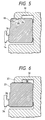
- the embodiment of Fig. 4 differs from the embodiment of Fig. 3 in that the recess 27 extends to the end surface of the rotating slide member 13 facing the stationary slide member 14. Therefore the recess 27 is not limited by a side wall on the side of the stationary slide member 14.
- the manufacturing of the rotating slide member 13 of the embodiment of Fig. 4 is easier than that of the embodiment of Fig. 3 if the rotating slide member 13 consists of silicon carbide. Nevertheless, with the construction of Fig. 4 falling out of the rotational slide member 13 is better prevented. However, since a step is formed only on one side, it is not so effective as the construction shown in Fig. 3 as regards the displacement of the rotating slide member 13.
- a circumferantial projection 28 extends radially inwardly from the cylindrical end surface 24 of the fitting porttion 23.
- the width of the projection 28 is smaller than the width of the cylindrical end surface 24.
- the width of the recess 27 substantially corresponds to the width of the projection 28.
- the projection 28 engages the recess 27 such that a shrinking stress exists between the projection 28 and the bottom of the recess 27.
- a plurality of projections 28 and recess 27 can be provided. This involves a better cooling effect for the sliding surface which leads to a better sealing performance.
Landscapes
- Engineering & Computer Science (AREA)
- General Engineering & Computer Science (AREA)
- Mechanical Engineering (AREA)
- Structures Of Non-Positive Displacement Pumps (AREA)
- Mechanical Sealing (AREA)
Abstract
Description
- The present invention relates to a mechanical seal for a compressor and to a centrifugal compressor comprising the mechanical seal.
- A conventional mechanical seal which is used for providing a seal between a casing and a shaft of a centrifugal compressor will be explained by means of Fig. 7 which shows the cross-sectional view of the main part of the conventional mechanical seal.
- Two annular rotating
slide members 33 are attached to anannular support member 32 by shrinkage. Theouter end surface 36 of eachslide member 33 forms a sliding surface which contacts an opposedstationary slide member 34 exerting an appropriate pressure on the rotatingslide member 33. The rotatingslide member 33 and thestationary slide member 34 prevent fluid from leaking out of a centrifugal compressor at the sliding area. The outer diameter of the rotatingslide member 33 is constant. - In order to determine the appropriate load for shrinkage fitting the stiffness of the materials of both slide members are to be taken in consideration. The slide members are required to have low friction at the slide surfaces thereof. Because a corrosive gas such as hydrogen sulfide is often dealt with, the slide members have to be resistant against corrosion. Finally the wear has to be small so that the slide members can be used for a period of at least 2 to 3 consecutive years.
- For the above mentioned reasons hard materials such as the SiC (silicon carbide) are appropriate for the slide members. However, silicon carbide is a brittle material so that when an excessive load is applied to the slide members, cracks may occur at the surface of the slide members.
- On the other hand, after shrink-fitting the
rotational slide member 33 and thesupport member 32 of the conventional mechanical seal of Fig. 7, therotational slide member 33 is supported at its periphery at theedge 38 of an inwardly extendingfitting portion 37 of thesupport member 32. Therefore, the shrinkage stress acts at an extremely small portion of the periphery of therotational slide member 33. This causes a stress concentration at a contacting area of the rotaional slidingmember 33 and thesupport member 32 which can generate a cracks on the outer surface of the rotatingslide member 33. - In order to reduce the stress concentration it can be considered to round the
edge 38 of thefitting portion 37 of thesupport member 32 as shown in Fig. 6. - However, the rounding of the
edge 38 does not prevent the rotatingslide member 33 from displacing in axial direction. It is further necessary to consider the additional radial stress which is caused by centrifugal forces. - The shrinkage stress becomes greater when the centrifugal compressor is operated at a higher speed. As the maximum shrinkage fitting load may not exceed a certain value, the shrinkage fitting load for installation has to be below a proper value.
- Therefore, an axially displacement or falling out of the rotating
slide member 33 may occur due to a lack of supporting force when an impact force is applied to the centrifugal compressor from outside during operation or installing thereof. - Further, when the above-described slide members are used in centrifugal compressor having a rated rotational speed of 5000-20000 rpm, a shaft power of 300-8000 kW, a shaft diameter of 100-200 mm and a seal pressure of 0. 5 - 2 MPa, the peripheral speed of the supporting portion becomes large and the supporting
member 32 may deflect by the centrifugal force. Therefore, a radial outward displacement of the rotatingslide member 33 occurs. This displacement causes a decrease of the amount of interference between the rotatingslide member 33 and thesupport member 32 during operation. - To overcome this inconvenience, it is needed to provide a larger amount of interference for shrinkage fitting in advance.
- In the Japanese Utility model laid-open 5-3737/1993, a mechanical seal made of ceramics is described. Though this seal has a face plate having a shoulder made of ceramics, it merely shows protection of debris coming into the seal region and does not show details how to use in a centrifugal compressor.
- It is the problem underlying the present invention to provide a mechanical seal which eliminates the above-mentioned inconveniences of the prior art, can be manufactured or processed easily and has a high reliability.
- Further a centrifugal compressor with a high speed and a high reliability seal is to be provided.
- This problem is solved by a mechanical seal for a compressor comprising
- a support member fixed to a rotary shaft for rotating therewith,
- an annular rotating slide member consisting of hard materials and being fitted to the support member by shrinkage; and
- a stationary slide member exerting pressure against an end surface of said rotating slide member;
- said rotating slide member comprises at least one peripheral recess formed by a portion of the periphery of said rotating slide member having a smaller outer diameter than the rest of the periphery; and
- said support member comprises an inwardly extending fitting portion engaging the peripheral recess.
- Advantegeously at least one of the edges of the fitting portion is rounded.
- When the mechanical seal is used for a centrifugal compressor having a rotating shaft with a diameter of 100-200 mm, a rated rotational speed of 5000-20000 rpm, a shaft power of 300-8000 kW and a seal pressure of 0.5-2 MPa, the outer diameter of the bottom of the peripheral recess is preferably smaller than the outer diameter of the rest of the periphery by 0.01-0.1 mm and/or the rounded edge of the fitting portion preferably has a radius of curvature of 0.05-0.2mm.
- In a preferred embodiment said rotating slide member has an increased heat transfer area.
- Conveniently said rotating slide member is made of silicon carbide.
- The mechanical seal of the present invention has a high reliabilty and a simple construction. Therefore it is easy to manufacture.
- A centrifugal compressor operated at a rated rotational speed of 5000-2000 rpm and a seal pressure of 0.52 MPa and including a rotating shaft having an outer diameter of 100 - 200 mm preferably comprises a mechanical seal of the present invention to have a high reliability.
- Embodiments of the invention are explained below in detail by means of the accompanying drawings.
-
- Fig. 1
- shows an axial cross-sectional view of a centrifugal compressor of the present invention;
- Fig. 2
- shows an axial cross-sectional view of a mechanical seal used in the centrifugal compressor of Fig. 1;
- Fig. 3
- shows a cross-sectional view of a principal portion of a first embodiment of the mechanical seal of the present invention;
- Fig. 4
- shows a cross-sectional view of a principal portion of a second embodiment of the mechanical seal of the present invention;
- Fig. 5
- shows a cross-sectional view of a principal portion of a third embodiment of the mechanical seal of the present invention;
- Fig. 6
- show a mechanical seal having a rounded edge at a fitting portion of support member;
- Fig. 7
- shows a cross-sectional view of a principal portion of a conventional mechanical seal.
- The multistage centrifugal compressor shown in Fig. 1 comprises a casing 1 in which a rotary shaft 2 is rotably supported by means of
bearings suction port 4 and adischarge port 5 are provided. Between thesuction port 4 and thedischarge port 5 several impellers 3 are attached to the rotary shaft 2 for rotating therewith. - Between the outermost impeller 3a on the suction side and the
corresponding bearing 7a amechanical seal 6a is provided preventing the leakage of fluid from the interior of the casing 1 to the exterior through the space between the shaft 2 and the casing 1. - Between the
outermost impeller 3b on the discharge side and thecorresponding bearing 7b a furthermechanical seal 6b is provided. - The overall construction of the mechanical seal is shown by means of
mechanical seal 6a in Fig. 2. Themechanical seal 6a comprises two annularrotating slide members 13 which are attached to the rotating shaft 2 by means of arotating support member 12 which is fixed to the shaft 2. - The
rotating slide members 13 and thesupport member 12 rotate together with the shaft 2. - The
mechanical seal 6a further comprisesstationary slide members 14 which exert an appropriate pressure to the opposed end surface of the correspondingrotating slide member 13 by means of aspring 15. Therefore gas inside the compressor is prevented from leaking to the exterior of the compressor at the slidingregion 17 at which therotating slide members 13 contact the correspondingstationary slide member 14. - Fig. 3 shows a detail of a mechanical seal for the use in a centrifugal compressor with a rated rotational speed of 5000-20000 rpm, a shaft power of 300-8000 kW, a shaft diameter of 100-200 mm and a seal pressure 0.5-2 MPa.
- An example of a appropriate centrifugal compressor has a rated rotational speed of 9990 rpm, a shaft power of 6670 kW, a shaft diameter of 140 mm at the seal location and a seal pressure of 0.7 MPa.
- The
rotating slide member 13 preferably consists of hard materials such as SiC (silicon carbide). Therefore, the friction at theslide surface 16 is low, corrosion resistance against corrosive gas, such as hydrogen sulfide, is excellent, and the wear is small, so that the seal can be used at least 2 to 3 consecutive years. - The
support member 12 consists of stainless steel. Thesupport member 12 comprises aninner ring element 20 which is fixed to the shaft 2 by shrinkage and a coaxialouter ring 21. Theinner ring element 20 and theouter ring element 21 are connected by aradially extending web 22. - At at least one axial end of the outer ring 21 a radially inwardly extending
fitting portion 23 runs along the inner periphery of theouter ring 21. Thefitting portion 23 comprises acylindrical end surface 24 extending between radially extending side surfaces 25, 26. - The
rotating slide member 13 is arranged between thefitting portion 23 and theinner ring element 20 such that it abuts with its other end surface against theweb 22. - In the area facing the
cylindrical end surface 24 of thefitting portion 23 the outer diameter of therotating slide member 13 is reduced in the axial direction by 0.01 to 0.1 mm, or preferably approximately 0.05 mm as shown in Fig. 3, so that arecess 27 is formed along the periphery of therotating slide member 13. Both side walls of therecess 27 are chamfered. Thus, the recess can be relatively easily manufactured even if a silicon carbide is used for therotating slide member 13. - The width of the
recess 27 is somewhat greater than the width of thefitting portion 23. Thefitting portion 23 engages therecess 27 such that thecylindrical end surface 24 contacts the bottom of therecess 27 and a predetermined shrinkage stress is provided between thecylindrical end surface 24 and the bottom of therecess 27. - Both edges 29 of the
fitting portion 23 are rounded with a radius of curvature of 0.05 -0.2 mm, preferably 0.1 mm, so that thefitting portion 23 does not interfere with the chamfered side walls of therecess 27. - As according to the present invention the
fitting portion 23 engages therecess 27 the support force against therotating slide member 13 can be gained for the compressor specified above without increasing the shrinkage fitting load during shrinkage fitting of therotating support member 12 androtating slide member 13. - In addition, a shrinkage stress concentration on the surfaces of the
rotating slide member 13 and thesupport member 12 is prevented by the rounding at bothedges 29 of thefitting portion 23. - The embodiment of Fig. 4 differs from the embodiment of Fig. 3 in that the
recess 27 extends to the end surface of therotating slide member 13 facing thestationary slide member 14. Therefore therecess 27 is not limited by a side wall on the side of thestationary slide member 14. - The manufacturing of the
rotating slide member 13 of the embodiment of Fig. 4 is easier than that of the embodiment of Fig. 3 if therotating slide member 13 consists of silicon carbide. Nevertheless, with the construction of Fig. 4 falling out of therotational slide member 13 is better prevented. However, since a step is formed only on one side, it is not so effective as the construction shown in Fig. 3 as regards the displacement of therotating slide member 13. - In the embodiment of the mechanical seal of Fig. 5 a
circumferantial projection 28 extends radially inwardly from thecylindrical end surface 24 of thefitting porttion 23. The width of theprojection 28 is smaller than the width of thecylindrical end surface 24. The width of therecess 27 substantially corresponds to the width of theprojection 28. Theprojection 28 engages therecess 27 such that a shrinking stress exists between theprojection 28 and the bottom of therecess 27. - In order to increase the heat transfer area a plurality of
projections 28 andrecess 27 can be provided. This involves a better cooling effect for the sliding surface which leads to a better sealing performance.
Claims (7)
- A mechanical seal for a compressor comprising:- a support member (12) fixed to a rotating shaft (2) for rotating therewith,- an annular rotating slide member (13) consisting of hard materials and being fitted to the support member (12) by shrinkage; and- a stationary slide member (14) exerting pressure against an end surface of said rotating slide member (13);characterized in that- said rotating slide member (13) comprises at least one peripheral recess (27) formed by a portion of the periphery of said rotating slide member (13), having a smaller outer diameter than the rest of the periphery; and- said support member (12) comprises an inwardly extending fitting portion (23) engaging the peripheral recess (27).
- A mechanical seal according to claim 1, wherein at least one of the edges (29) of the fitting portion (23) is rounded.
- A mechanical seal according to one of the preceding claims for a centrifugal compressor having a rotating shaft with a diameter of 100 - 200 mm, a rated rotational speed of 5000 - 20000 rpm, a shaft power of 300-8000 kW and a seal pressure of 0.5 - 2 MPa,
characterized in thatthe outer diameter of the bottom of the peripheral recess (27) is smaller than outer diameter of the rest of the periphery by 0.01 - 0.1 mm. - A mechanical seal according to one of the preceding claims for a centrifugal compressor having a rotating shaft with a diameter of 100 - 200 mm, a rated rotational speed of 5000 - 20000 rpm, a shaft power of 300 - 8000 kW and a seal pressure of 0.5 - 2 MPa, characterized in that the rounded edge (29) of the fitting portion has a radius of curvature of 0.05 - 0.2 mm.
- A mechanical seal according to one of the preceding claims, characterized in that said rotating slide member (13) has an increased heat transfer area.
- A mechanical seal according to one of the preceding claims, characterized in that said rotating slide member (13) is made of silicon carbide.
- A centrifugal compressor operated at a rated rotational speed of 5000 - 2000 rpm and a seal pressure of 0.5 - 2 MPa and comprising a rotating shaft having an outer diameter of 100 - 200 mm; characterized by a mechanical seal (6a, 6b) according to one of the claims 1 to 6.
Applications Claiming Priority (3)
| Application Number | Priority Date | Filing Date | Title |
|---|---|---|---|
| JP307131/95 | 1995-11-27 | ||
| JP7307131A JPH09144893A (en) | 1995-11-27 | 1995-11-27 | Mechanical seal and centrifugal compressor |
| JP30713195 | 1995-11-27 |
Publications (2)
| Publication Number | Publication Date |
|---|---|
| EP0775859A1 true EP0775859A1 (en) | 1997-05-28 |
| EP0775859B1 EP0775859B1 (en) | 2002-04-03 |
Family
ID=17965408
Family Applications (1)
| Application Number | Title | Priority Date | Filing Date |
|---|---|---|---|
| EP96118394A Expired - Lifetime EP0775859B1 (en) | 1995-11-27 | 1996-11-15 | Mechanical seal for a compressor and centrifugal compressor comprising the mechanical seal |
Country Status (5)
| Country | Link |
|---|---|
| US (1) | US5897118A (en) |
| EP (1) | EP0775859B1 (en) |
| JP (1) | JPH09144893A (en) |
| CN (1) | CN1069749C (en) |
| DE (1) | DE69620349T2 (en) |
Cited By (2)
| Publication number | Priority date | Publication date | Assignee | Title |
|---|---|---|---|---|
| EP3208502A1 (en) * | 2016-02-16 | 2017-08-23 | Rolls-Royce Corporation | Ceramic seal runner and mount for a rotating shaft |
| US11054039B2 (en) | 2018-08-31 | 2021-07-06 | Rolls-Royce Corporation | Seal runner support |
Families Citing this family (7)
| Publication number | Priority date | Publication date | Assignee | Title |
|---|---|---|---|---|
| US6655695B1 (en) | 2001-02-13 | 2003-12-02 | Honeywell International Inc. | Face seal assembly with composite rotor |
| DE10301613B4 (en) * | 2003-01-17 | 2006-08-31 | Pierburg Gmbh | Motor-pump unit |
| JP2006214289A (en) * | 2005-02-01 | 2006-08-17 | Hitachi Industries Co Ltd | Industrial pump and manufacturing method thereof |
| US20070022873A1 (en) * | 2005-07-26 | 2007-02-01 | Honeywell International Inc. | Wear-resistant port plate for a fluid transfer device and fluid transfer device including same |
| US7708285B2 (en) * | 2005-10-21 | 2010-05-04 | A.W. Chesterton Company | Elastomer spring mechanical seal |
| US20070228664A1 (en) * | 2006-03-31 | 2007-10-04 | Krishnamurthy Anand | Mechanical seals and methods of making |
| WO2020235632A1 (en) * | 2019-05-23 | 2020-11-26 | イーグルブルグマンジャパン株式会社 | Mechanical seal |
Citations (6)
| Publication number | Priority date | Publication date | Assignee | Title |
|---|---|---|---|---|
| DE2246536A1 (en) * | 1971-09-27 | 1973-04-12 | Durametallic Corp | SEALING DEVICE |
| DE3428744A1 (en) * | 1983-08-12 | 1985-02-28 | Dickow-Pumpen KG, 8264 Waldkraiburg | Fixing of annular silicon-carbide components on metal supporting parts |
| DE3539100A1 (en) * | 1984-11-06 | 1986-05-15 | Osakeyhtiö Safematic Ltd., Hyrylä | MECHANICAL SEAL |
| FR2576077A1 (en) * | 1985-01-16 | 1986-07-18 | Safematic Ltd Oy | SLIDING RING JOINT |
| GB2185546A (en) * | 1986-01-22 | 1987-07-22 | Safematic Ltd Oy | Slide ring seal |
| JPH053737U (en) | 1991-06-27 | 1993-01-22 | 三菱重工業株式会社 | Static pressure seal with back thinning |
Family Cites Families (8)
| Publication number | Priority date | Publication date | Assignee | Title |
|---|---|---|---|---|
| US2425209A (en) * | 1944-08-31 | 1947-08-05 | Crane Packing Co | Seat for mechanical seals |
| US2447930A (en) * | 1947-02-15 | 1948-08-24 | Gits Bros Mfg Co | High-speed oil seal |
| SE347334B (en) * | 1970-12-30 | 1972-07-31 | Stenberg Flygt Ab | |
| US4261581A (en) * | 1980-04-14 | 1981-04-14 | Durametallic Corporation | Mechanical seal with improved face ring mounting |
| CN87201287U (en) * | 1987-04-23 | 1988-01-13 | 江苏工学院 | Anti-wearing mechanism seal |
| CN1011383B (en) * | 1988-05-15 | 1991-01-30 | 中山大学 | Extraction and Concentration Process of Coconut Milk |
| US4890851A (en) * | 1989-01-19 | 1990-01-02 | Durametallic Corporation | Bellows seal with vibration damper |
| US5042824A (en) * | 1990-02-08 | 1991-08-27 | Eg&G Sealol, Inc. | Balanced shrink fit seal ring assembly |
-
1995
- 1995-11-27 JP JP7307131A patent/JPH09144893A/en active Pending
-
1996
- 1996-11-15 DE DE69620349T patent/DE69620349T2/en not_active Expired - Fee Related
- 1996-11-15 EP EP96118394A patent/EP0775859B1/en not_active Expired - Lifetime
- 1996-11-25 CN CN96121806A patent/CN1069749C/en not_active Expired - Fee Related
- 1996-11-27 US US08/757,568 patent/US5897118A/en not_active Expired - Fee Related
Patent Citations (6)
| Publication number | Priority date | Publication date | Assignee | Title |
|---|---|---|---|---|
| DE2246536A1 (en) * | 1971-09-27 | 1973-04-12 | Durametallic Corp | SEALING DEVICE |
| DE3428744A1 (en) * | 1983-08-12 | 1985-02-28 | Dickow-Pumpen KG, 8264 Waldkraiburg | Fixing of annular silicon-carbide components on metal supporting parts |
| DE3539100A1 (en) * | 1984-11-06 | 1986-05-15 | Osakeyhtiö Safematic Ltd., Hyrylä | MECHANICAL SEAL |
| FR2576077A1 (en) * | 1985-01-16 | 1986-07-18 | Safematic Ltd Oy | SLIDING RING JOINT |
| GB2185546A (en) * | 1986-01-22 | 1987-07-22 | Safematic Ltd Oy | Slide ring seal |
| JPH053737U (en) | 1991-06-27 | 1993-01-22 | 三菱重工業株式会社 | Static pressure seal with back thinning |
Cited By (4)
| Publication number | Priority date | Publication date | Assignee | Title |
|---|---|---|---|---|
| EP3208502A1 (en) * | 2016-02-16 | 2017-08-23 | Rolls-Royce Corporation | Ceramic seal runner and mount for a rotating shaft |
| US10174845B2 (en) | 2016-02-16 | 2019-01-08 | Rolls-Royce Corporation | Ceramic seal runner and mount for a rotating shaft |
| US10544866B2 (en) | 2016-02-16 | 2020-01-28 | Rolls-Royce Corporation | Ceramic seal runner and mount for a rotating shaft |
| US11054039B2 (en) | 2018-08-31 | 2021-07-06 | Rolls-Royce Corporation | Seal runner support |
Also Published As
| Publication number | Publication date |
|---|---|
| DE69620349T2 (en) | 2002-11-28 |
| CN1155040A (en) | 1997-07-23 |
| EP0775859B1 (en) | 2002-04-03 |
| DE69620349D1 (en) | 2002-05-08 |
| US5897118A (en) | 1999-04-27 |
| CN1069749C (en) | 2001-08-15 |
| JPH09144893A (en) | 1997-06-03 |
Similar Documents
| Publication | Publication Date | Title |
|---|---|---|
| EP0473018B1 (en) | Compliant finger seal | |
| KR100999015B1 (en) | Turbo machine | |
| EP0470409B1 (en) | Noncontacting face seal | |
| JP5197157B2 (en) | Screw fluid machine | |
| EP2318738B1 (en) | Leaf seal | |
| EP3592982B1 (en) | A bearing arrangement for a drive shaft of a turbo-machine, and a turbo-machine including such a bearing arrangement | |
| US9188134B2 (en) | Flow machine for a fluid having a radial sealing gap and a stationary wear ring | |
| EP0775859B1 (en) | Mechanical seal for a compressor and centrifugal compressor comprising the mechanical seal | |
| EP0492603A2 (en) | Liner ring for a pump | |
| CN108368875A (en) | Film bearing | |
| US20060088238A1 (en) | Ball bearing and a vacuum pump that is equipped with a bearing of this type | |
| CN118434999A (en) | Grease suppressor | |
| KR20000035609A (en) | Turbo molecular pump and vacuum apparatus | |
| EA013364B1 (en) | Flexible floating ring seal arrangement rotodynamic pumps | |
| EP0719943B1 (en) | Bearing device for use in a pump | |
| JP3912926B2 (en) | Floating machine floating seal | |
| JP2006183475A (en) | Centrifugal compressor | |
| EP3436703B1 (en) | Impeller-type liquid ring compressor | |
| JP4314654B2 (en) | Axial force balance device | |
| JP5546464B2 (en) | Turbo molecular pump | |
| EP0806571B1 (en) | A rotatable assembly for supporting the rotor of a vacuum pump | |
| US5833374A (en) | Rotatable assembly for supporting of the rotor of a vacuum pump | |
| CN218407614U (en) | Turbojet engine and sealing structure thereof | |
| JP4103709B2 (en) | Screw compressor | |
| JP2002257081A (en) | Leak preventing device for volute pump |
Legal Events
| Date | Code | Title | Description |
|---|---|---|---|
| PUAI | Public reference made under article 153(3) epc to a published international application that has entered the european phase |
Free format text: ORIGINAL CODE: 0009012 |
|
| 17P | Request for examination filed |
Effective date: 19961115 |
|
| AK | Designated contracting states |
Kind code of ref document: A1 Designated state(s): CH DE IT LI |
|
| 17Q | First examination report despatched |
Effective date: 19990916 |
|
| GRAG | Despatch of communication of intention to grant |
Free format text: ORIGINAL CODE: EPIDOS AGRA |
|
| GRAG | Despatch of communication of intention to grant |
Free format text: ORIGINAL CODE: EPIDOS AGRA |
|
| GRAH | Despatch of communication of intention to grant a patent |
Free format text: ORIGINAL CODE: EPIDOS IGRA |
|
| GRAH | Despatch of communication of intention to grant a patent |
Free format text: ORIGINAL CODE: EPIDOS IGRA |
|
| GRAA | (expected) grant |
Free format text: ORIGINAL CODE: 0009210 |
|
| AK | Designated contracting states |
Kind code of ref document: B1 Designated state(s): CH DE IT LI |
|
| REG | Reference to a national code |
Ref country code: CH Ref legal event code: EP |
|
| REF | Corresponds to: |
Ref document number: 69620349 Country of ref document: DE Date of ref document: 20020508 |
|
| REG | Reference to a national code |
Ref country code: CH Ref legal event code: NV Representative=s name: TROESCH SCHEIDEGGER WERNER AG |
|
| PLBE | No opposition filed within time limit |
Free format text: ORIGINAL CODE: 0009261 |
|
| STAA | Information on the status of an ep patent application or granted ep patent |
Free format text: STATUS: NO OPPOSITION FILED WITHIN TIME LIMIT |
|
| 26N | No opposition filed |
Effective date: 20030106 |
|
| PGFP | Annual fee paid to national office [announced via postgrant information from national office to epo] |
Ref country code: CH Payment date: 20030923 Year of fee payment: 8 |
|
| PGFP | Annual fee paid to national office [announced via postgrant information from national office to epo] |
Ref country code: DE Payment date: 20031203 Year of fee payment: 8 |
|
| PG25 | Lapsed in a contracting state [announced via postgrant information from national office to epo] |
Ref country code: LI Free format text: LAPSE BECAUSE OF NON-PAYMENT OF DUE FEES Effective date: 20041130 Ref country code: CH Free format text: LAPSE BECAUSE OF NON-PAYMENT OF DUE FEES Effective date: 20041130 |
|
| PG25 | Lapsed in a contracting state [announced via postgrant information from national office to epo] |
Ref country code: DE Free format text: LAPSE BECAUSE OF NON-PAYMENT OF DUE FEES Effective date: 20050601 |
|
| REG | Reference to a national code |
Ref country code: CH Ref legal event code: PL |
|
| PG25 | Lapsed in a contracting state [announced via postgrant information from national office to epo] |
Ref country code: IT Free format text: LAPSE BECAUSE OF NON-PAYMENT OF DUE FEES;WARNING: LAPSES OF ITALIAN PATENTS WITH EFFECTIVE DATE BEFORE 2007 MAY HAVE OCCURRED AT ANY TIME BEFORE 2007. THE CORRECT EFFECTIVE DATE MAY BE DIFFERENT FROM THE ONE RECORDED. Effective date: 20051115 |