EP0775805B1 - Stator shroud - Google Patents
Stator shroud Download PDFInfo
- Publication number
- EP0775805B1 EP0775805B1 EP96308446A EP96308446A EP0775805B1 EP 0775805 B1 EP0775805 B1 EP 0775805B1 EP 96308446 A EP96308446 A EP 96308446A EP 96308446 A EP96308446 A EP 96308446A EP 0775805 B1 EP0775805 B1 EP 0775805B1
- Authority
- EP
- European Patent Office
- Prior art keywords
- seal
- segment
- shroud
- blade outer
- passages
- Prior art date
- Legal status (The legal status is an assumption and is not a legal conclusion. Google has not performed a legal analysis and makes no representation as to the accuracy of the status listed.)
- Expired - Lifetime
Links
Images

Classifications
-
- F—MECHANICAL ENGINEERING; LIGHTING; HEATING; WEAPONS; BLASTING
- F01—MACHINES OR ENGINES IN GENERAL; ENGINE PLANTS IN GENERAL; STEAM ENGINES
- F01P—COOLING OF MACHINES OR ENGINES IN GENERAL; COOLING OF INTERNAL-COMBUSTION ENGINES
- F01P5/00—Pumping cooling-air or liquid coolants
- F01P5/02—Pumping cooling-air; Arrangements of cooling-air pumps, e.g. fans or blowers
-
- F—MECHANICAL ENGINEERING; LIGHTING; HEATING; WEAPONS; BLASTING
- F01—MACHINES OR ENGINES IN GENERAL; ENGINE PLANTS IN GENERAL; STEAM ENGINES
- F01D—NON-POSITIVE DISPLACEMENT MACHINES OR ENGINES, e.g. STEAM TURBINES
- F01D11/00—Preventing or minimising internal leakage of working-fluid, e.g. between stages
- F01D11/08—Preventing or minimising internal leakage of working-fluid, e.g. between stages for sealing space between rotor blade tips and stator
-
- F—MECHANICAL ENGINEERING; LIGHTING; HEATING; WEAPONS; BLASTING
- F01—MACHINES OR ENGINES IN GENERAL; ENGINE PLANTS IN GENERAL; STEAM ENGINES
- F01D—NON-POSITIVE DISPLACEMENT MACHINES OR ENGINES, e.g. STEAM TURBINES
- F01D11/00—Preventing or minimising internal leakage of working-fluid, e.g. between stages
- F01D11/005—Sealing means between non relatively rotating elements
-
- F—MECHANICAL ENGINEERING; LIGHTING; HEATING; WEAPONS; BLASTING
- F01—MACHINES OR ENGINES IN GENERAL; ENGINE PLANTS IN GENERAL; STEAM ENGINES
- F01D—NON-POSITIVE DISPLACEMENT MACHINES OR ENGINES, e.g. STEAM TURBINES
- F01D25/00—Component parts, details, or accessories, not provided for in, or of interest apart from, other groups
- F01D25/24—Casings; Casing parts, e.g. diaphragms, casing fastenings
- F01D25/246—Fastening of diaphragms or stator-rings
-
- F—MECHANICAL ENGINEERING; LIGHTING; HEATING; WEAPONS; BLASTING
- F05—INDEXING SCHEMES RELATING TO ENGINES OR PUMPS IN VARIOUS SUBCLASSES OF CLASSES F01-F04
- F05D—INDEXING SCHEME FOR ASPECTS RELATING TO NON-POSITIVE-DISPLACEMENT MACHINES OR ENGINES, GAS-TURBINES OR JET-PROPULSION PLANTS
- F05D2240/00—Components
- F05D2240/55—Seals
- F05D2240/56—Brush seals
Definitions
- This invention relates to turbine engine rotor assemblies in general, and to rotor assembly shrouds, blade outer air seals therefor and air seal body segments in particular.
- a typical gas turbine engine includes a fan, compressor, combustor, and turbine disposed along a common longitudinal axis.
- the fan and compressor sections work the air drawn into the engine, increasing the pressure and temperature of the air.
- Fuel is added to the worked air and burned within the combustor.
- the combustion products and any unburned air hereinafter referred to as core gas flow, subsequently powers the turbine and exits the engine producing thrust.
- the turbine comprises several stages each having a rotor assembly and at least one stationary vane assembly.
- the core gas flow causes the rotor assemblies to rotate, thereby enabling the rotor assemblies to do work elsewhere in the engine.
- the stationary vane assemblies located forward and/or aft of the rotor assemblies guide the core gas flow entering and/or exiting the rotor assemblies.
- a shroud is disposed radially outside of the rotor assembly for sealing between the turbine case and the rotor assembly.
- the shroud includes a blade outer air seal generally formed from a plurality of segments disposed side by side around the circumference of the rotor assembly. The blade outer air seal segments are suspended in close proximity to the tips of the rotor blades.
- the extremely high temperature of the core gas flow passing through the turbine necessitates cooling within many of the turbine components. This is particularly true for blade outer air seals.
- the shroud components are cooled by air bled off the compressor at a temperature lower and a pressure greater than that of the core gas flow.
- compressor worked air for cooling purposes, however.
- the bled air cools where access is provided and the higher pressure of the bled air prevents detrimental in-flow of hot core gas.
- air bled off of the compressor does not do as much work as it might otherwise and consequently decreases the efficiency of the engine. This is particularly true when excessive bled air is used for cooling purposes because of undesirable leaks in the cooling path.
- Blade outer air seal segments may be biased within the shroud to ensure proper sealing between the blade outer air seal and whatever hardware is adjacent the seal, and to prevent detrimental vibration. Vibration can cause blade outer air seal segments to wear prematurely.
- Some prior art shrouds use a ring to aggregately bias the blade outer air seal segments around the circumference of the shroud. A difficulty with this approach is that segments will vary in size within their tolerance range. If, in the assembly of the shroud, several "full" segments are placed adjacent a "thin” segment, the biasing force of the ring may not be applied to the thin segment as completely as it is applied to the full segments. As a result, a space between the thin segment and the ring may be created that provides an undesirable leak path for bled air. In addition, the thin segment may be more readily excited, and therefore prone to vibration.
- US 4050843 describes a gas turbine engine with a blade outer air seal segment for a shroud including passages for receiving cooling air.
- the segments are supported by axially extending levers.
- US 5395212 describes a gas turbine blade with internal passages provided with ribs and fins for enhanced transfer of heat within the cooling flow passage.
- a rotor assembly shroud that uses a minimum of bled air, one that is durable, one that is easily maintained, and one that utilizes readily replaceable parts.
- the invention provides a blade outer air seal body segment for a rotor assembly shroud comprising: a first face, a second face, and a plurality of passages for receiving cooling air disposed between said faces; means for suspending said segment within the shroud, said means for suspending extending out from said second face of said segment; and means for biasing each said body segment within the shroud, characterised in that said means for biasing comprises a post, extending out from said second face of said body segment for engagement within the shroud, assembly of said blade outer air seal within the shroud causing said post to deflect, thereby biasing said body segment within the shroud.
- the invention also extends to an air seal and shroud containing a segment in accordance with the invention.
- a shroud for a rotor assembly comprising a mounting ring, an aft seal ring, a forward seal ring, and a blade outer air seal.
- the mounting ring is fixed within the casing surrounding the rotor assembly, and includes a first attachment means.
- the blade outer air seal includes a plurality of body segments. Each body segment includes a first face, a second face, a plurality of passages for receiving cooling air disposed between the faces, a second attachment means, and a post for biasing each body segment in contact with the aft seal ring.
- the first and second attachment means cooperate to suspend the blade outer seal segments in close proximity to the rotor assembly.
- means for augmenting the transfer of heat within the passages is provided disposed within the passages.
- opposite edges of the blade outer air seal segments form mating shiplap halves. Cooling passages are disposed within the mating shiplap halves to prevent thermal damage.
- a shroud 10 is disposed between a rotor assembly 12 and the casing 14 surrounding the rotor assembly 12 within the turbine of a gas turbine engine (not shown).
- the rotor assembly 12 includes a plurality of blades 16 circumferentially disposed around a disk (not shown).
- the outer radial surface 18 of each blade may be referred to as the tip 18.
- the shroud 10 is disposed in an annulus 20 radially between the casing 14 and the blade tips 18 of the rotor assembly 12, and axially between forward 22 and aft 24 outer vane supports.
- the shroud 10 includes a mounting ring 26, a blade outer air seal 28, an aft seal ring 30, and a forward seal ring 32.
- the mounting ring 26 includes an outer 34 and an inner 36 radial surface. A press fit between the outer radial surface 34 and the casing 14 fixes the mounting ring 26 within the casing 14.
- the mounting ring 26 further includes a first attachment means 38 which includes a plurality of "L"-shaped flanges 40 extending out from the inner radial surface 36.
- the blade outer air seal 28 is formed from a plurality of body segments 42 connected to one another, which collectively form a ring suspended by the mounting ring 26 (see FIG.1) around the periphery of the rotor assembly 12.
- Each body segment 42 includes a first face 44, a second face 46, a forward edge 48, an aft edge 50, a first 52 and a second 54 circumferential edge, and a plurality of passages 56.
- the passages 56 are formed from channels disposed in the second face 46 with one or more plates 60 secured to the second face 46 to close the channels into passages 56.
- the passages 56 are formed internally within the segment 42, between the first 44 and second 46 faces.
- the first 52 and a second 54 circumferential edges are formed as mating shiplap joint halves, respectively (see FIG.3).
- the passages 56 extend into the shiplap halves 52,54 and include ports 55 which allow cooling air to pass through the shiplap halves 52,54 and outside of the segment 42.
- Each shiplap half 52,54 mates with the half from the adjacent segment 42 to form the shiplap joint 51.
- Feather seals 53 extend between adjacent segments 42 to prevent leakage between segments 42.
- each blade outer air seal segment 42 includes a second attachment means 66 having a plurality of upside down "L"-shaped flanges 68 extending out from the second face 46 of each segment 42.
- the flanges 68 extending out from the segments 42 cooperate with the flanges 40 extending out from the mounting ring 26 to suspend the segments 42.
- Each blade outer air seal segment 42 further includes a post 72 for biasing each segment 42 within the shroud 10.
- the post 72 extends out from the second face 46 of the segment 42, adjacent the aft edge 50 of the segment 42.
- the height of the post 72 is such that the post 72 contacts the mounting ring 26 once the shroud 10 is assembled.
- the post 72 provides a defined spring force for a specific amount of deflection.
- means 74 for augmenting heat transfer within the passages 56 may be included within the passages 56.
- the means 74 for augmenting includes a plurality of chevron shaped fins 76 extending into the passages 56.
- the crowns 78, or points, of the chevron shaped fins 76 are directed against the flow path of bled air within the passages 56 as is shown by the directional arrows in FIG.4.
- the forward 32 and aft 30 seal rings are brush seals positioned to seal between blade outer air seal 28 and the forward 22 and aft 24 outer vane supports, respectively.
- the forward seal ring 32 is positioned between the blade outer air seal 28, the mounting ring 26, and the forward outer vane support 22.
- the aft seal ring 30 is positioned between the blade outer air seal 28 and the aft outer vane support 24.
- the aft outer vane support 24 biases the aft seal ring 30 against the blade outer air seal 28, thereby aggregately biasing the second attachment means 66 of the blade outer air seal segments 42 within the first attachment means 38 of the mounting ring 26.
- the post 72 extending out from the second face 46 of each segment 42 biases each individual segment 42 against the aft seal ring 30.
- core gas flow passes through the engine and more specifically past the rotor assembly 12 within the turbine.
- the core gas flow drives the rotor assembly 12 and the rotor assembly, in turn, drives the compressor (not shown).
- a first method for minimizing the use of blade air is to use the bled air effectively.
- the cooling passages 56 extending into the shiplaps 52,54 help protect the shiplaps with a minimal amount of bled air.
- the chevrons fins 76 disposed within the passages 56 similarly help to optimize the heat transfer between the blade outer air seal segments 42 and the bled air passing through the passages 56.
- the second method preventing bled air leakage, is accomplished by the posts 72 extending out from the second face 46 of each blade outer seal segment 42.
- the blade outer air seal segments 42 are aggregately biased against the mounting ring 26 by the aft outer vane support 24 acting against the aft seal ring 30.
- the present invention provides a rotor assembly shroud that includes adequate cooling means, that minimizes leakage of bled air from the shroud, that does not appreciably vibrate, if at all, which has optimal heat transfer, and therefore minimal cooling air requirements, which is easily manufactured and assembled, and which has blade outer air seals that are readily replaceable.
- each blade outer air seal segment biases each segment individually against the aft seal ring. Vibration and any gap that may have existed between the segment and the aft seal ring are therefore minimized.
- the shiplap pairs help maintain the integrity of the blade outer air seal in the event of contact between the rotor blades and the blade outer air seal.
- the shiplap pairs also protect the feather seals extending between adjacent blade outer air seal segments.
- the cooling passages within each body segment extend into the inner and outer halves of each shiplap pair to transfer heat away from the shiplap pairs.
- the cooling air requirements of the shroud overall, and the blade outer air seal in particular, are minimized.
- the means for augmenting heat transfer, disposed within the passages of each segment, increases the rate of heat transfer in the passages. Hence, less cooling air is required to provide the necessary amount of heat transfer.
- shroud is more readily manufactured, assembled, and maintained. Biasing the blade outer air seal segments individually obviates the need to machine the segments collectively, and allows a greater tolerance range for the width of each individual segment. In addition, worn segments can later be replaced without having to custom fit the particular segments.
Description
- This invention relates to turbine engine rotor assemblies in general, and to rotor assembly shrouds, blade outer air seals therefor and air seal body segments in particular.
- A typical gas turbine engine includes a fan, compressor, combustor, and turbine disposed along a common longitudinal axis. The fan and compressor sections work the air drawn into the engine, increasing the pressure and temperature of the air. Fuel is added to the worked air and burned within the combustor. The combustion products and any unburned air, hereinafter referred to as core gas flow, subsequently powers the turbine and exits the engine producing thrust. In most cases, the turbine comprises several stages each having a rotor assembly and at least one stationary vane assembly. The core gas flow causes the rotor assemblies to rotate, thereby enabling the rotor assemblies to do work elsewhere in the engine. The stationary vane assemblies located forward and/or aft of the rotor assemblies guide the core gas flow entering and/or exiting the rotor assemblies.
- A shroud is disposed radially outside of the rotor assembly for sealing between the turbine case and the rotor assembly. The shroud includes a blade outer air seal generally formed from a plurality of segments disposed side by side around the circumference of the rotor assembly. The blade outer air seal segments are suspended in close proximity to the tips of the rotor blades.
- The extremely high temperature of the core gas flow passing through the turbine necessitates cooling within many of the turbine components. This is particularly true for blade outer air seals. The shroud components are cooled by air bled off the compressor at a temperature lower and a pressure greater than that of the core gas flow. There is a trade-off using compressor worked air for cooling purposes, however. On the one hand, the bled air cools where access is provided and the higher pressure of the bled air prevents detrimental in-flow of hot core gas. On the other hand, air bled off of the compressor does not do as much work as it might otherwise and consequently decreases the efficiency of the engine. This is particularly true when excessive bled air is used for cooling purposes because of undesirable leaks in the cooling path.
- Blade outer air seal segments may be biased within the shroud to ensure proper sealing between the blade outer air seal and whatever hardware is adjacent the seal, and to prevent detrimental vibration. Vibration can cause blade outer air seal segments to wear prematurely. Some prior art shrouds use a ring to aggregately bias the blade outer air seal segments around the circumference of the shroud. A difficulty with this approach is that segments will vary in size within their tolerance range. If, in the assembly of the shroud, several "full" segments are placed adjacent a "thin" segment, the biasing force of the ring may not be applied to the thin segment as completely as it is applied to the full segments. As a result, a space between the thin segment and the ring may be created that provides an undesirable leak path for bled air. In addition, the thin segment may be more readily excited, and therefore prone to vibration.
- The leakage and vibration problems caused by the tolerance range of the segment widths can be resolved by machining all of the segments together as an assembly to produce a single machined surface. Machining the blade outer air seal as an assembly is, however, a difficult and expensive task. In addition, if one or more of the "machined" blade outer air seal segments later needed to be replaced, that replacement would have to be custom machined as well.
- US 4050843 describes a gas turbine engine with a blade outer air seal segment for a shroud including passages for receiving cooling air. The segments are supported by axially extending levers.
- US 5395212 describes a gas turbine blade with internal passages provided with ribs and fins for enhanced transfer of heat within the cooling flow passage.
- Hence, what is needed is a rotor assembly shroud that uses a minimum of bled air, one that is durable, one that is easily maintained, and one that utilizes readily replaceable parts.
- From a first broad aspect, the invention provides a blade outer air seal body segment for a rotor assembly shroud comprising: a first face, a second face, and a plurality of passages for receiving cooling air disposed between said faces; means for suspending said segment within the shroud, said means for suspending extending out from said second face of said segment; and means for biasing each said body segment within the shroud, characterised in that said means for biasing comprises a post, extending out from said second face of said body segment for engagement within the shroud, assembly of said blade outer air seal within the shroud causing said post to deflect, thereby biasing said body segment within the shroud.
- The invention also extends to an air seal and shroud containing a segment in accordance with the invention.
- According to one embodiment of the present invention, a shroud for a rotor assembly is provided comprising a mounting ring, an aft seal ring, a forward seal ring, and a blade outer air seal. The mounting ring is fixed within the casing surrounding the rotor assembly, and includes a first attachment means. The blade outer air seal includes a plurality of body segments. Each body segment includes a first face, a second face, a plurality of passages for receiving cooling air disposed between the faces, a second attachment means, and a post for biasing each body segment in contact with the aft seal ring. The first and second attachment means cooperate to suspend the blade outer seal segments in close proximity to the rotor assembly.
- According to a preferred feature of the present invention, means for augmenting the transfer of heat within the passages is provided disposed within the passages.
- According to another preferred feature of the present invention, opposite edges of the blade outer air seal segments form mating shiplap halves. Cooling passages are disposed within the mating shiplap halves to prevent thermal damage.
- A preferred embodiment of the invention will now be described with reference to the accompanying drawings, in which:-
- Fig. 1 is a diagrammatic sectional view of the shroud disposed within the casing;
- Fig. 2 is a diagrammatic top view of a blade outer air seal segment;
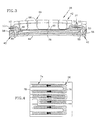
- Fig. 3 is a diagrammatic sectional view of blade outer air seal segments; and
- Fig. 4 is a diagrammatic view of the passages within a blade outer seal segment.
-
- Referring to Fig. 1, a
shroud 10 is disposed between arotor assembly 12 and thecasing 14 surrounding therotor assembly 12 within the turbine of a gas turbine engine (not shown). Therotor assembly 12 includes a plurality ofblades 16 circumferentially disposed around a disk (not shown). The outerradial surface 18 of each blade may be referred to as thetip 18. - The
shroud 10 is disposed in anannulus 20 radially between thecasing 14 and theblade tips 18 of therotor assembly 12, and axially between forward 22 andaft 24 outer vane supports. Theshroud 10 includes amounting ring 26, a bladeouter air seal 28, anaft seal ring 30, and aforward seal ring 32. Themounting ring 26 includes an outer 34 and an inner 36 radial surface. A press fit between the outerradial surface 34 and thecasing 14 fixes themounting ring 26 within thecasing 14. Themounting ring 26 further includes a first attachment means 38 which includes a plurality of "L"-shaped flanges 40 extending out from the innerradial surface 36. - Referring to FIGS. 2-4, the blade
outer air seal 28 is formed from a plurality ofbody segments 42 connected to one another, which collectively form a ring suspended by the mounting ring 26 (see FIG.1) around the periphery of therotor assembly 12. Eachbody segment 42 includes afirst face 44, asecond face 46, aforward edge 48, anaft edge 50, a first 52 and a second 54 circumferential edge, and a plurality ofpassages 56. In a first embodiment, thepassages 56 are formed from channels disposed in thesecond face 46 with one ormore plates 60 secured to thesecond face 46 to close the channels intopassages 56. In a second embodiment, thepassages 56 are formed internally within thesegment 42, between the first 44 and second 46 faces. The first 52 and a second 54 circumferential edges are formed as mating shiplap joint halves, respectively (see FIG.3). Thepassages 56 extend into theshiplap halves ports 55 which allow cooling air to pass through theshiplap halves segment 42. Eachshiplap half adjacent segment 42 to form theshiplap joint 51.Feather seals 53 extend betweenadjacent segments 42 to prevent leakage betweensegments 42. - Referring to FIG.1, each blade outer
air seal segment 42 includes a second attachment means 66 having a plurality of upside down "L"-shaped flanges 68 extending out from thesecond face 46 of eachsegment 42. Theflanges 68 extending out from thesegments 42 cooperate with theflanges 40 extending out from themounting ring 26 to suspend thesegments 42. - Each blade outer
air seal segment 42 further includes apost 72 for biasing eachsegment 42 within theshroud 10. Thepost 72 extends out from thesecond face 46 of thesegment 42, adjacent theaft edge 50 of thesegment 42. The height of thepost 72 is such that thepost 72 contacts the mountingring 26 once theshroud 10 is assembled. Thepost 72 provides a defined spring force for a specific amount of deflection. - Referring to FIG.4, means 74 for augmenting heat transfer within the
passages 56 may be included within thepassages 56. In the preferred embodiment, themeans 74 for augmenting includes a plurality of chevron shapedfins 76 extending into thepassages 56. Thecrowns 78, or points, of the chevron shapedfins 76 are directed against the flow path of bled air within thepassages 56 as is shown by the directional arrows in FIG.4. - Referring to FIG.1, the forward 32 and aft 30 seal rings are brush seals positioned to seal between blade
outer air seal 28 and the forward 22 and aft 24 outer vane supports, respectively. Theforward seal ring 32 is positioned between the bladeouter air seal 28, the mountingring 26, and the forwardouter vane support 22. Theaft seal ring 30 is positioned between the bladeouter air seal 28 and the aftouter vane support 24. The aftouter vane support 24 biases theaft seal ring 30 against the bladeouter air seal 28, thereby aggregately biasing the second attachment means 66 of the blade outerair seal segments 42 within the first attachment means 38 of the mountingring 26. Thepost 72 extending out from thesecond face 46 of eachsegment 42 biases eachindividual segment 42 against theaft seal ring 30. - During operation of the engine, core gas flow passes through the engine and more specifically past the
rotor assembly 12 within the turbine. The core gas flow drives therotor assembly 12 and the rotor assembly, in turn, drives the compressor (not shown). Air bled off from the compressor upstream of the turbine, at a temperature lower and a pressure higher than that of the core gas flow, is passed through thecasing 14 to cool thecasing 14 and theshroud 10. - Referring to FIG. 3, because a significant percentage of the work imparted to the air by the compressor is lost when used for cooling purposes, it is a considerable advantage to minimize the amount of bled air required for cooling purposes. A first method for minimizing the use of blade air is to use the bled air effectively. The
cooling passages 56 extending into theshiplaps chevrons fins 76 disposed within thepassages 56 similarly help to optimize the heat transfer between the blade outerair seal segments 42 and the bled air passing through thepassages 56. - Referring to FIG. 1, the second method, preventing bled air leakage, is accomplished by the
posts 72 extending out from thesecond face 46 of each bladeouter seal segment 42. The blade outerair seal segments 42 are aggregately biased against the mountingring 26 by the aftouter vane support 24 acting against theaft seal ring 30. Theposts 72 extending out from thesegments 42, adjacent theaft edge 50, resist the loading of the aftouter vane support 24 and bias eachindividual segment 42 against theaft seal ring 30. In effect theposts 72 act as resilient biasing means, providing a defined biasing force for a specific amount of deflection. In the event a "thin"width segment 42 is positioned next to one or more "full"segments 42, the individual biasing provided by theposts 72 ensures that the "thin"segment 42 is biased against theaft seal ring 30. As a result, any leakage that might have occurred between theindividual segment 42 and theaft seal ring 30 due to tolerancing is minimized, as well as any detrimental vibration. - From the above, it will be seen that in its preferred embodiments at least, the present invention provides a rotor assembly shroud that includes adequate cooling means, that minimizes leakage of bled air from the shroud, that does not appreciably vibrate, if at all, which has optimal heat transfer, and therefore minimal cooling air requirements, which is easily manufactured and assembled, and which has blade outer air seals that are readily replaceable.
- It will be seen that the bled air leakage and vibration of blade outer seal segments are minimized. The post extending out from each blade outer air seal segment biases each segment individually against the aft seal ring. Vibration and any gap that may have existed between the segment and the aft seal ring are therefore minimized.
- Also, increased mechanical protection and thermal resistance is provided by the cooled shiplap joints formed between adjacent blade outer air seal segments. The shiplap pairs help maintain the integrity of the blade outer air seal in the event of contact between the rotor blades and the blade outer air seal. The shiplap pairs also protect the feather seals extending between adjacent blade outer air seal segments. The cooling passages within each body segment extend into the inner and outer halves of each shiplap pair to transfer heat away from the shiplap pairs.
- Furthermore, the cooling air requirements of the shroud overall, and the blade outer air seal in particular, are minimized. The means for augmenting heat transfer, disposed within the passages of each segment, increases the rate of heat transfer in the passages. Hence, less cooling air is required to provide the necessary amount of heat transfer.
- Moreover, the shroud is more readily manufactured, assembled, and maintained. Biasing the blade outer air seal segments individually obviates the need to machine the segments collectively, and allows a greater tolerance range for the width of each individual segment. In addition, worn segments can later be replaced without having to custom fit the particular segments.
- Although this invention has been shown and described with respect to a detailed embodiments thereof, it will be understood by those skilled in the art that various changes in form and detail thereof may be made without departing from the scope of the invention as defined in the appended claims. For example, it is disclosed in the described embodiment that aft seal ring biases the blade outer seal ring. In alternative embodiments, other surfaces may be used to bias the blade outer air seal.
Claims (9)
- A blade outer air seal body segment (42) for a rotor assembly shroud comprising:a first face (44), a second face (46), and a plurality of passages (56) for receiving cooling air disposed between said faces;means (66) for suspending said segment within the shroud, said means for suspending extending out from said second face (46) of said segment; andmeans for biasing each said body segment within the shroud, characterised in that;said means for biasing comprises a post (72), extending out from said second face (46) of said body segment for engagement within the shroud,assembly of said blade outer air seal within the shroud causing said post to deflect, thereby biasing said body segment within the shroud.
- A blade outer air seal (28) comprising a plurality of segments (42) as claimed in claim 1.
- A seal or segment according to claim 1 or 2, further comprising means (74) for augmenting the transfer of heat within said passages (56).
- A seal or seal segment according to claim 3, wherein said means (74) for augmenting the transfer of heat within said passages (56) comprises a plurality of chevron shaped fins (76) disposed within said passages.
- A seal or seal segment according to any preceding claim, wherein the or each said body segment (42) further comprises:wherein said first edge (52) of a first body segment mates with said second edge (54) of an adjacent body segment to join said body segments.a first edge (52), formed as a first half of a mating shiplap pair;a second edge (54), opposite said first edge, formed as a second half of a mating shiplap pair;
- A seal or seal segment according to claim 5, wherein the or each said body segment (42) further comprises passages extending into said halves of said mating shiplap pairs, said passages permitting cooling air into said mating shiplap halves.
- A seal or seal segment according to any preceding claim, wherein said means for suspending said seal segment (42) comprises:wherein said flanges are shaped such that they form a sideways "U" shape with said second face side (46).a plurality of first flanges (68) extending out from said second face side (46);a plurality of second flanges (68) extending out from said second face side (46);
- A shroud for a rotor assembly, comprising a blade outer air seal as claimed in any of claims 2 to 7.
- A shroud according to claim 8, wherein said shroud comprises a mounting ring (26), fixed within a casing (14), said mounting ring having a first attachment means (38) and an aft seal ring (30), each said segment (42) of said seal having a second attachment means (66), extending out from said second face of each said segment, and cooperating with said first attachment means (38) to suspend said blade outer air seal from said mounting ring, said post (72) acting to bias each said body segment in contact with said aft seal ring.
Applications Claiming Priority (2)
| Application Number | Priority Date | Filing Date | Title |
|---|---|---|---|
| US08/561,767 US5609469A (en) | 1995-11-22 | 1995-11-22 | Rotor assembly shroud |
| US561767 | 2000-04-29 |
Publications (3)
| Publication Number | Publication Date |
|---|---|
| EP0775805A2 EP0775805A2 (en) | 1997-05-28 |
| EP0775805A3 EP0775805A3 (en) | 1999-03-31 |
| EP0775805B1 true EP0775805B1 (en) | 2002-09-11 |
Family
ID=24243371
Family Applications (1)
| Application Number | Title | Priority Date | Filing Date |
|---|---|---|---|
| EP96308446A Expired - Lifetime EP0775805B1 (en) | 1995-11-22 | 1996-11-21 | Stator shroud |
Country Status (5)
| Country | Link |
|---|---|
| US (1) | US5609469A (en) |
| EP (1) | EP0775805B1 (en) |
| JP (1) | JPH09151705A (en) |
| KR (1) | KR100379728B1 (en) |
| DE (1) | DE69623574T2 (en) |
Families Citing this family (82)
| Publication number | Priority date | Publication date | Assignee | Title |
|---|---|---|---|---|
| US5823741A (en) * | 1996-09-25 | 1998-10-20 | General Electric Co. | Cooling joint connection for abutting segments in a gas turbine engine |
| US6393331B1 (en) | 1998-12-16 | 2002-05-21 | United Technologies Corporation | Method of designing a turbine blade outer air seal |
| US6170831B1 (en) * | 1998-12-23 | 2001-01-09 | United Technologies Corporation | Axial brush seal for gas turbine engines |
| FR2800797B1 (en) * | 1999-11-10 | 2001-12-07 | Snecma | ASSEMBLY OF A RING BORDING A TURBINE TO THE TURBINE STRUCTURE |
| US6422815B1 (en) | 2000-03-02 | 2002-07-23 | General Electric Company | Turbine air seal replacement rings |
| EP1247943A1 (en) | 2001-04-04 | 2002-10-09 | Siemens Aktiengesellschaft | Coolable turbine shroud member |
| EP1256695A1 (en) * | 2001-05-07 | 2002-11-13 | Siemens Aktiengesellschaft | Element for a gas turbine guiding ring and gas turbine comprising such element |
| US6896483B2 (en) | 2001-07-02 | 2005-05-24 | Allison Advanced Development Company | Blade track assembly |
| US6733233B2 (en) | 2002-04-26 | 2004-05-11 | Pratt & Whitney Canada Corp. | Attachment of a ceramic shroud in a metal housing |
| US6814538B2 (en) | 2003-01-22 | 2004-11-09 | General Electric Company | Turbine stage one shroud configuration and method for service enhancement |
| ES2316994T3 (en) * | 2003-08-11 | 2009-04-16 | Siemens Aktiengesellschaft | GAS TURBINE WITH AN OBTAINING ELEMENT IN THE REGION OF THE CROWN OF ALABES GUIA OR THE CROWN OF ALABES DE PALETA OF THE PART OF TURBINA. |
| US20060078429A1 (en) * | 2004-10-08 | 2006-04-13 | Darkins Toby G Jr | Turbine engine shroud segment |
| KR100654240B1 (en) * | 2004-12-30 | 2006-12-06 | 두산메카텍 주식회사 | Machining Center with Unify Power of Tool Unclamp and Tool Chang |
| DE102005013798A1 (en) * | 2005-03-24 | 2006-09-28 | Alstom Technology Ltd. | Heat release segment for sealing a flow channel of a flow rotary machine |
| US7621719B2 (en) * | 2005-09-30 | 2009-11-24 | United Technologies Corporation | Multiple cooling schemes for turbine blade outer air seal |
| FR2899274B1 (en) * | 2006-03-30 | 2012-08-17 | Snecma | DEVICE FOR FASTENING RING SECTIONS AROUND A TURBINE WHEEL OF A TURBOMACHINE |
| US7771160B2 (en) * | 2006-08-10 | 2010-08-10 | United Technologies Corporation | Ceramic shroud assembly |
| US7665960B2 (en) | 2006-08-10 | 2010-02-23 | United Technologies Corporation | Turbine shroud thermal distortion control |
| US7553128B2 (en) * | 2006-10-12 | 2009-06-30 | United Technologies Corporation | Blade outer air seals |
| US7665961B2 (en) * | 2006-11-28 | 2010-02-23 | United Technologies Corporation | Turbine outer air seal |
| US20090096174A1 (en) * | 2007-02-28 | 2009-04-16 | United Technologies Corporation | Blade outer air seal for a gas turbine engine |
| US8439629B2 (en) | 2007-03-01 | 2013-05-14 | United Technologies Corporation | Blade outer air seal |
| US8123466B2 (en) * | 2007-03-01 | 2012-02-28 | United Technologies Corporation | Blade outer air seal |
| US7874792B2 (en) * | 2007-10-01 | 2011-01-25 | United Technologies Corporation | Blade outer air seals, cores, and manufacture methods |
| US8240980B1 (en) | 2007-10-19 | 2012-08-14 | Florida Turbine Technologies, Inc. | Turbine inter-stage gap cooling and sealing arrangement |
| US20090110546A1 (en) * | 2007-10-29 | 2009-04-30 | United Technologies Corp. | Feather Seals and Gas Turbine Engine Systems Involving Such Seals |
| US8177492B2 (en) * | 2008-03-04 | 2012-05-15 | United Technologies Corporation | Passage obstruction for improved inlet coolant filling |
| US20090274562A1 (en) * | 2008-05-02 | 2009-11-05 | United Technologies Corporation | Coated turbine-stage nozzle segments |
| US8317461B2 (en) * | 2008-08-27 | 2012-11-27 | United Technologies Corporation | Gas turbine engine component having dual flow passage cooling chamber formed by single core |
| US8365405B2 (en) * | 2008-08-27 | 2013-02-05 | United Technologies Corp. | Preforms and related methods for repairing abradable seals of gas turbine engines |
| US8534995B2 (en) * | 2009-03-05 | 2013-09-17 | United Technologies Corporation | Turbine engine sealing arrangement |
| US20110044803A1 (en) * | 2009-08-18 | 2011-02-24 | Pratt & Whitney Canada Corp. | Blade outer air seal anti-rotation |
| US8167546B2 (en) * | 2009-09-01 | 2012-05-01 | United Technologies Corporation | Ceramic turbine shroud support |
| US8727695B2 (en) * | 2009-12-09 | 2014-05-20 | Rolls-Royce Corporation | Chamfer-fillet gap for thermal management |
| US8556575B2 (en) * | 2010-03-26 | 2013-10-15 | United Technologies Corporation | Blade outer seal for a gas turbine engine |
| US8876458B2 (en) | 2011-01-25 | 2014-11-04 | United Technologies Corporation | Blade outer air seal assembly and support |
| US8834106B2 (en) * | 2011-06-01 | 2014-09-16 | United Technologies Corporation | Seal assembly for gas turbine engine |
| US20130170979A1 (en) * | 2012-01-04 | 2013-07-04 | General Electric Company | Double ended brush seal assembly for a compressor |
| US9097129B2 (en) | 2012-05-31 | 2015-08-04 | United Technologies Corporation | Segmented seal with ship lap ends |
| US8998572B2 (en) | 2012-06-04 | 2015-04-07 | United Technologies Corporation | Blade outer air seal for a gas turbine engine |
| US20140064942A1 (en) * | 2012-08-31 | 2014-03-06 | General Electric Company | Turbine rotor blade platform cooling |
| US9587504B2 (en) | 2012-11-13 | 2017-03-07 | United Technologies Corporation | Carrier interlock |
| US9371738B2 (en) | 2012-12-20 | 2016-06-21 | United Technologies Corporation | Variable outer air seal support |
| US9255524B2 (en) | 2012-12-20 | 2016-02-09 | United Technologies Corporation | Variable outer air seal fluid control |
| WO2014158589A1 (en) * | 2013-03-13 | 2014-10-02 | United Technologies Corporation | Multi-axial brush seal |
| US10451204B2 (en) | 2013-03-15 | 2019-10-22 | United Technologies Corporation | Low leakage duct segment using expansion joint assembly |
| EP3080419B1 (en) * | 2013-12-12 | 2021-04-07 | Raytheon Technologies Corporation | Wrapped dog bone seal |
| US9879557B2 (en) * | 2014-08-15 | 2018-01-30 | United Technologies Corporation | Inner stage turbine seal for gas turbine engine |
| US10329934B2 (en) | 2014-12-15 | 2019-06-25 | United Technologies Corporation | Reversible flow blade outer air seal |
| GB201508551D0 (en) | 2015-05-19 | 2015-07-01 | Rolls Royce Plc | A heat exchanger for a gas turbine engine |
| US9803496B2 (en) * | 2015-07-01 | 2017-10-31 | United Technologies Corporation | Break-in system for gapping and leakage control |
| EP3173587B1 (en) * | 2015-11-30 | 2021-03-31 | MTU Aero Engines GmbH | Housing for a fluid flow engine, securing device and fluid flow engine |
| US10202864B2 (en) * | 2016-02-09 | 2019-02-12 | United Technologies Corporation | Chevron trip strip |
| US10801345B2 (en) | 2016-02-09 | 2020-10-13 | Raytheon Technologies Corporation | Chevron trip strip |
| US10138749B2 (en) | 2016-03-16 | 2018-11-27 | United Technologies Corporation | Seal anti-rotation feature |
| US10415414B2 (en) | 2016-03-16 | 2019-09-17 | United Technologies Corporation | Seal arc segment with anti-rotation feature |
| US10563531B2 (en) | 2016-03-16 | 2020-02-18 | United Technologies Corporation | Seal assembly for gas turbine engine |
| US10443424B2 (en) | 2016-03-16 | 2019-10-15 | United Technologies Corporation | Turbine engine blade outer air seal with load-transmitting carriage |
| US10422240B2 (en) | 2016-03-16 | 2019-09-24 | United Technologies Corporation | Turbine engine blade outer air seal with load-transmitting cover plate |
| US10337346B2 (en) | 2016-03-16 | 2019-07-02 | United Technologies Corporation | Blade outer air seal with flow guide manifold |
| US10161258B2 (en) | 2016-03-16 | 2018-12-25 | United Technologies Corporation | Boas rail shield |
| US10138750B2 (en) | 2016-03-16 | 2018-11-27 | United Technologies Corporation | Boas segmented heat shield |
| US10107129B2 (en) | 2016-03-16 | 2018-10-23 | United Technologies Corporation | Blade outer air seal with spring centering |
| US10132184B2 (en) | 2016-03-16 | 2018-11-20 | United Technologies Corporation | Boas spring loaded rail shield |
| US10443616B2 (en) | 2016-03-16 | 2019-10-15 | United Technologies Corporation | Blade outer air seal with centrally mounted seal arc segments |
| US10422241B2 (en) | 2016-03-16 | 2019-09-24 | United Technologies Corporation | Blade outer air seal support for a gas turbine engine |
| US10513943B2 (en) | 2016-03-16 | 2019-12-24 | United Technologies Corporation | Boas enhanced heat transfer surface |
| US20170292395A1 (en) * | 2016-04-07 | 2017-10-12 | United Technologies Corporation | Integrated brush seals |
| US10352183B2 (en) | 2016-04-25 | 2019-07-16 | United Technologies Corporation | High temperature seal and method |
| CN108533722B (en) * | 2018-04-13 | 2023-10-20 | 南京高速齿轮制造有限公司 | Brush type sealing structure suitable for gear box |
| US10738651B2 (en) * | 2018-05-31 | 2020-08-11 | General Electric Company | Shroud for gas turbine engine |
| US10815807B2 (en) * | 2018-05-31 | 2020-10-27 | General Electric Company | Shroud and seal for gas turbine engine |
| US10633995B2 (en) * | 2018-07-31 | 2020-04-28 | United Technologies Corporation | Sealing surface for ceramic matrix composite blade outer air seal |
| US10787923B2 (en) * | 2018-08-27 | 2020-09-29 | Raytheon Technologies Corporation | Axially preloaded seal |
| US10815810B2 (en) * | 2019-01-10 | 2020-10-27 | Raytheon Technologies Corporation | BOAS assemblies with axial support pins |
| US11015473B2 (en) * | 2019-03-18 | 2021-05-25 | Raytheon Technologies Corporation | Carrier for blade outer air seal |
| US11255208B2 (en) | 2019-05-15 | 2022-02-22 | Raytheon Technologies Corporation | Feather seal for CMC BOAS |
| US11773751B1 (en) | 2022-11-29 | 2023-10-03 | Rolls-Royce Corporation | Ceramic matrix composite blade track segment with pin-locating threaded insert |
| US11713694B1 (en) | 2022-11-30 | 2023-08-01 | Rolls-Royce Corporation | Ceramic matrix composite blade track segment with two-piece carrier |
| US11840936B1 (en) | 2022-11-30 | 2023-12-12 | Rolls-Royce Corporation | Ceramic matrix composite blade track segment with pin-locating shim kit |
| US11732604B1 (en) | 2022-12-01 | 2023-08-22 | Rolls-Royce Corporation | Ceramic matrix composite blade track segment with integrated cooling passages |
| US11885225B1 (en) | 2023-01-25 | 2024-01-30 | Rolls-Royce Corporation | Turbine blade track with ceramic matrix composite segments having attachment flange draft angles |
Family Cites Families (16)
| Publication number | Priority date | Publication date | Assignee | Title |
|---|---|---|---|---|
| GB1484936A (en) * | 1974-12-07 | 1977-09-08 | Rolls Royce | Gas turbine engines |
| US4144433A (en) * | 1976-12-16 | 1979-03-13 | General Electric Company | Method for metal bonding |
| US4416585A (en) * | 1980-01-17 | 1983-11-22 | Pratt & Whitney Aircraft Of Canada Limited | Blade cooling for gas turbine engine |
| US4551064A (en) * | 1982-03-05 | 1985-11-05 | Rolls-Royce Limited | Turbine shroud and turbine shroud assembly |
| US5039562A (en) * | 1988-10-20 | 1991-08-13 | The United States Of America As Represented By The Secretary Of The Air Force | Method and apparatus for cooling high temperature ceramic turbine blade portions |
| US5022816A (en) * | 1989-10-24 | 1991-06-11 | United Technologies Corporation | Gas turbine blade shroud support |
| JPH03213602A (en) * | 1990-01-08 | 1991-09-19 | General Electric Co <Ge> | Self cooling type joint connecting structure to connect contact segment of gas turbine engine |
| US5127793A (en) * | 1990-05-31 | 1992-07-07 | General Electric Company | Turbine shroud clearance control assembly |
| GB9103809D0 (en) * | 1991-02-23 | 1991-04-10 | Rolls Royce Plc | Blade tip clearance control apparatus |
| JP3006174B2 (en) * | 1991-07-04 | 2000-02-07 | 株式会社日立製作所 | Member having a cooling passage inside |
| US5197853A (en) * | 1991-08-28 | 1993-03-30 | General Electric Company | Airtight shroud support rail and method for assembling in turbine engine |
| US5188507A (en) * | 1991-11-27 | 1993-02-23 | General Electric Company | Low-pressure turbine shroud |
| FR2691749B1 (en) * | 1992-05-27 | 1994-07-22 | Snecma | SEALING DEVICE BETWEEN STAGES OF BLADES AND A TURNING DRUM IN PARTICULAR TO AVOID LEAKS AROUND THE STAGES OF RECTIFIER BLADES. |
| US5333992A (en) * | 1993-02-05 | 1994-08-02 | United Technologies Corporation | Coolable outer air seal assembly for a gas turbine engine |
| US5486090A (en) * | 1994-03-30 | 1996-01-23 | United Technologies Corporation | Turbine shroud segment with serpentine cooling channels |
| US5423659A (en) * | 1994-04-28 | 1995-06-13 | United Technologies Corporation | Shroud segment having a cut-back retaining hook |
-
1995
- 1995-11-22 US US08/561,767 patent/US5609469A/en not_active Expired - Lifetime
-
1996
- 1996-11-19 JP JP8322181A patent/JPH09151705A/en active Pending
- 1996-11-21 KR KR1019960056150A patent/KR100379728B1/en not_active IP Right Cessation
- 1996-11-21 EP EP96308446A patent/EP0775805B1/en not_active Expired - Lifetime
- 1996-11-21 DE DE69623574T patent/DE69623574T2/en not_active Expired - Lifetime
Also Published As
| Publication number | Publication date |
|---|---|
| DE69623574D1 (en) | 2002-10-17 |
| EP0775805A2 (en) | 1997-05-28 |
| JPH09151705A (en) | 1997-06-10 |
| KR100379728B1 (en) | 2003-10-17 |
| EP0775805A3 (en) | 1999-03-31 |
| DE69623574T2 (en) | 2003-01-09 |
| US5609469A (en) | 1997-03-11 |
| KR970027684A (en) | 1997-06-24 |
Similar Documents
| Publication | Publication Date | Title |
|---|---|---|
| EP0775805B1 (en) | Stator shroud | |
| EP0357984B1 (en) | Gas turbine with film cooling of turbine vane shrouds | |
| US8419356B2 (en) | Turbine seal assembly | |
| US9850775B2 (en) | Turbine shroud segment sealing | |
| EP1502009B1 (en) | Attachment of a ceramic shroud in a metal housing | |
| US5244345A (en) | Rotor | |
| EP0867599B1 (en) | Method and apparatus for sealing a gas turbine stator vane assembly | |
| US5215435A (en) | Angled cooling air bypass slots in honeycomb seals | |
| US4573867A (en) | Housing for turbomachine rotors | |
| US7234918B2 (en) | Gap control system for turbine engines | |
| US7165937B2 (en) | Methods and apparatus for maintaining rotor assembly tip clearances | |
| US4688988A (en) | Coolable stator assembly for a gas turbine engine | |
| EP1348834A2 (en) | Aspirating face seal with axially biasing one-piece annular spring | |
| US8388310B1 (en) | Turbine disc sealing assembly | |
| JPH086609B2 (en) | Brush seal device and balancing piston device | |
| JPH08506640A (en) | Coolable outer air seal device for gas turbine engine | |
| CA2031085A1 (en) | Arrangement for sealing gaps between adjacent circumferential segments of turbine nozzles and shrouds | |
| JPS59507A (en) | Heat shield device for radial gas turbine | |
| US6571470B1 (en) | Method of retrofitting seals in a gas turbine | |
| US11905886B2 (en) | Heatshield for a gas turbine engine | |
| EP3543468B1 (en) | Turbine tip shroud assembly with plural shroud segments having inter-segment seal arrangement | |
| KR20220159874A (en) | Gas turbine inner shroud with abradable surface feature |
Legal Events
| Date | Code | Title | Description |
|---|---|---|---|
| PUAI | Public reference made under article 153(3) epc to a published international application that has entered the european phase |
Free format text: ORIGINAL CODE: 0009012 |
|
| AK | Designated contracting states |
Kind code of ref document: A2 Designated state(s): DE FR GB |
|
| PUAL | Search report despatched |
Free format text: ORIGINAL CODE: 0009013 |
|
| AK | Designated contracting states |
Kind code of ref document: A3 Designated state(s): DE FR GB |
|
| 17P | Request for examination filed |
Effective date: 19990602 |
|
| 17Q | First examination report despatched |
Effective date: 20010306 |
|
| GRAG | Despatch of communication of intention to grant |
Free format text: ORIGINAL CODE: EPIDOS AGRA |
|
| GRAG | Despatch of communication of intention to grant |
Free format text: ORIGINAL CODE: EPIDOS AGRA |
|
| GRAH | Despatch of communication of intention to grant a patent |
Free format text: ORIGINAL CODE: EPIDOS IGRA |
|
| GRAH | Despatch of communication of intention to grant a patent |
Free format text: ORIGINAL CODE: EPIDOS IGRA |
|
| GRAA | (expected) grant |
Free format text: ORIGINAL CODE: 0009210 |
|
| AK | Designated contracting states |
Kind code of ref document: B1 Designated state(s): DE FR GB |
|
| REG | Reference to a national code |
Ref country code: GB Ref legal event code: FG4D |
|
| REF | Corresponds to: |
Ref document number: 69623574 Country of ref document: DE Date of ref document: 20021017 |
|
| ET | Fr: translation filed | ||
| PLBE | No opposition filed within time limit |
Free format text: ORIGINAL CODE: 0009261 |
|
| STAA | Information on the status of an ep patent application or granted ep patent |
Free format text: STATUS: NO OPPOSITION FILED WITHIN TIME LIMIT |
|
| 26N | No opposition filed |
Effective date: 20030612 |
|
| PG25 | Lapsed in a contracting state [announced via postgrant information from national office to epo] |
Ref country code: FR Free format text: LAPSE BECAUSE OF NON-PAYMENT OF DUE FEES Effective date: 20060731 |
|
| REG | Reference to a national code |
Ref country code: FR Ref legal event code: ST Effective date: 20060731 |
|
| REG | Reference to a national code |
Ref country code: FR Ref legal event code: D3 |
|
| PGFP | Annual fee paid to national office [announced via postgrant information from national office to epo] |
Ref country code: FR Payment date: 20081106 Year of fee payment: 13 |
|
| REG | Reference to a national code |
Ref country code: FR Ref legal event code: ST Effective date: 20100730 |
|
| PGFP | Annual fee paid to national office [announced via postgrant information from national office to epo] |
Ref country code: DE Payment date: 20121114 Year of fee payment: 17 |
|
| PGFP | Annual fee paid to national office [announced via postgrant information from national office to epo] |
Ref country code: GB Payment date: 20121121 Year of fee payment: 17 |
|
| GBPC | Gb: european patent ceased through non-payment of renewal fee |
Effective date: 20131121 |
|
| REG | Reference to a national code |
Ref country code: DE Ref legal event code: R119 Ref document number: 69623574 Country of ref document: DE Effective date: 20140603 |
|
| PG25 | Lapsed in a contracting state [announced via postgrant information from national office to epo] |
Ref country code: DE Free format text: LAPSE BECAUSE OF NON-PAYMENT OF DUE FEES Effective date: 20140603 |
|
| PG25 | Lapsed in a contracting state [announced via postgrant information from national office to epo] |
Ref country code: GB Free format text: LAPSE BECAUSE OF NON-PAYMENT OF DUE FEES Effective date: 20131121 |
|
| PG25 | Lapsed in a contracting state [announced via postgrant information from national office to epo] |
Ref country code: FR Free format text: LAPSE BECAUSE OF NON-PAYMENT OF DUE FEES Effective date: 20091130 |