EP0775527A1 - Venturi insulator for use in an electrostatic precipitator - Google Patents
Venturi insulator for use in an electrostatic precipitator Download PDFInfo
- Publication number
- EP0775527A1 EP0775527A1 EP97200339A EP97200339A EP0775527A1 EP 0775527 A1 EP0775527 A1 EP 0775527A1 EP 97200339 A EP97200339 A EP 97200339A EP 97200339 A EP97200339 A EP 97200339A EP 0775527 A1 EP0775527 A1 EP 0775527A1
- Authority
- EP
- European Patent Office
- Prior art keywords
- tie rod
- flow
- hole
- venturi
- fluid
- Prior art date
- Legal status (The legal status is an assumption and is not a legal conclusion. Google has not performed a legal analysis and makes no representation as to the accuracy of the status listed.)
- Withdrawn
Links
- 239000012717 electrostatic precipitator Substances 0.000 title claims abstract description 21
- 239000012212 insulator Substances 0.000 title description 56
- 239000012530 fluid Substances 0.000 claims abstract description 54
- 239000012716 precipitator Substances 0.000 claims description 24
- 239000000356 contaminant Substances 0.000 claims description 18
- 238000004140 cleaning Methods 0.000 claims description 12
- 238000000034 method Methods 0.000 claims description 9
- 230000007423 decrease Effects 0.000 claims description 6
- 230000001133 acceleration Effects 0.000 claims description 2
- 230000003134 recirculating effect Effects 0.000 abstract 1
- 125000006850 spacer group Chemical group 0.000 description 27
- 239000002245 particle Substances 0.000 description 10
- 239000007789 gas Substances 0.000 description 7
- 239000000463 material Substances 0.000 description 7
- 230000003247 decreasing effect Effects 0.000 description 3
- 230000000694 effects Effects 0.000 description 3
- 239000011521 glass Substances 0.000 description 3
- 239000011810 insulating material Substances 0.000 description 3
- 229920001225 polyester resin Polymers 0.000 description 3
- 239000004645 polyester resin Substances 0.000 description 3
- 229920001187 thermosetting polymer Polymers 0.000 description 3
- 239000000919 ceramic Substances 0.000 description 2
- 239000012777 electrically insulating material Substances 0.000 description 2
- 238000001556 precipitation Methods 0.000 description 2
- OKTJSMMVPCPJKN-UHFFFAOYSA-N Carbon Chemical compound [C] OKTJSMMVPCPJKN-UHFFFAOYSA-N 0.000 description 1
- SEQDDYPDSLOBDC-UHFFFAOYSA-N Temazepam Chemical compound N=1C(O)C(=O)N(C)C2=CC=C(Cl)C=C2C=1C1=CC=CC=C1 SEQDDYPDSLOBDC-UHFFFAOYSA-N 0.000 description 1
- 238000009825 accumulation Methods 0.000 description 1
- 238000004026 adhesive bonding Methods 0.000 description 1
- XAGFODPZIPBFFR-UHFFFAOYSA-N aluminium Chemical compound [Al] XAGFODPZIPBFFR-UHFFFAOYSA-N 0.000 description 1
- 229910052782 aluminium Inorganic materials 0.000 description 1
- 230000000712 assembly Effects 0.000 description 1
- 238000000429 assembly Methods 0.000 description 1
- 229910052799 carbon Inorganic materials 0.000 description 1
- 238000000576 coating method Methods 0.000 description 1
- 238000009833 condensation Methods 0.000 description 1
- 230000005494 condensation Effects 0.000 description 1
- 239000004020 conductor Substances 0.000 description 1
- 238000007796 conventional method Methods 0.000 description 1
- 239000000428 dust Substances 0.000 description 1
- 238000004070 electrodeposition Methods 0.000 description 1
- 230000005686 electrostatic field Effects 0.000 description 1
- 238000005367 electrostatic precipitation Methods 0.000 description 1
- 239000003295 industrial effluent Substances 0.000 description 1
- 238000002347 injection Methods 0.000 description 1
- 239000007924 injection Substances 0.000 description 1
- 238000010849 ion bombardment Methods 0.000 description 1
- 150000002500 ions Chemical class 0.000 description 1
- 239000007788 liquid Substances 0.000 description 1
- 239000000203 mixture Substances 0.000 description 1
- 239000012811 non-conductive material Substances 0.000 description 1
- 230000009972 noncorrosive effect Effects 0.000 description 1
- 239000004033 plastic Substances 0.000 description 1
- 229910052573 porcelain Inorganic materials 0.000 description 1
- 230000002028 premature Effects 0.000 description 1
- 230000001681 protective effect Effects 0.000 description 1
- 238000009877 rendering Methods 0.000 description 1
- 230000000284 resting effect Effects 0.000 description 1
- 230000035939 shock Effects 0.000 description 1
- 239000007787 solid Substances 0.000 description 1
- 239000000725 suspension Substances 0.000 description 1
- 238000011144 upstream manufacturing Methods 0.000 description 1
- 238000009423 ventilation Methods 0.000 description 1
Images






Classifications
-
- B—PERFORMING OPERATIONS; TRANSPORTING
- B03—SEPARATION OF SOLID MATERIALS USING LIQUIDS OR USING PNEUMATIC TABLES OR JIGS; MAGNETIC OR ELECTROSTATIC SEPARATION OF SOLID MATERIALS FROM SOLID MATERIALS OR FLUIDS; SEPARATION BY HIGH-VOLTAGE ELECTRIC FIELDS
- B03C—MAGNETIC OR ELECTROSTATIC SEPARATION OF SOLID MATERIALS FROM SOLID MATERIALS OR FLUIDS; SEPARATION BY HIGH-VOLTAGE ELECTRIC FIELDS
- B03C3/00—Separating dispersed particles from gases or vapour, e.g. air, by electrostatic effect
- B03C3/02—Plant or installations having external electricity supply
- B03C3/04—Plant or installations having external electricity supply dry type
- B03C3/12—Plant or installations having external electricity supply dry type characterised by separation of ionising and collecting stations
-
- B—PERFORMING OPERATIONS; TRANSPORTING
- B03—SEPARATION OF SOLID MATERIALS USING LIQUIDS OR USING PNEUMATIC TABLES OR JIGS; MAGNETIC OR ELECTROSTATIC SEPARATION OF SOLID MATERIALS FROM SOLID MATERIALS OR FLUIDS; SEPARATION BY HIGH-VOLTAGE ELECTRIC FIELDS
- B03C—MAGNETIC OR ELECTROSTATIC SEPARATION OF SOLID MATERIALS FROM SOLID MATERIALS OR FLUIDS; SEPARATION BY HIGH-VOLTAGE ELECTRIC FIELDS
- B03C3/00—Separating dispersed particles from gases or vapour, e.g. air, by electrostatic effect
- B03C3/34—Constructional details or accessories or operation thereof
- B03C3/66—Applications of electricity supply techniques
- B03C3/70—Applications of electricity supply techniques insulating in electric separators
-
- Y—GENERAL TAGGING OF NEW TECHNOLOGICAL DEVELOPMENTS; GENERAL TAGGING OF CROSS-SECTIONAL TECHNOLOGIES SPANNING OVER SEVERAL SECTIONS OF THE IPC; TECHNICAL SUBJECTS COVERED BY FORMER USPC CROSS-REFERENCE ART COLLECTIONS [XRACs] AND DIGESTS
- Y02—TECHNOLOGIES OR APPLICATIONS FOR MITIGATION OR ADAPTATION AGAINST CLIMATE CHANGE
- Y02A—TECHNOLOGIES FOR ADAPTATION TO CLIMATE CHANGE
- Y02A50/00—TECHNOLOGIES FOR ADAPTATION TO CLIMATE CHANGE in human health protection, e.g. against extreme weather
- Y02A50/20—Air quality improvement or preservation, e.g. vehicle emission control or emission reduction by using catalytic converters
- Y02A50/2351—Atmospheric particulate matter [PM], e.g. carbon smoke microparticles, smog, aerosol particles, dust
Definitions
- the present invention relates to electrical precipitators of the electrostatic type.
- the invention relates to an insulator for use in an electrostatic precipitator.
- Electrostatic precipitators are used to remove contaminants, such as liquid droplets and solid particles, from a fluid in which they are suspended.
- the precipitation process typically includes at least two basic steps. First, the contaminated suspension is ionized by passing it through an electrical corona. The ions produced in the fluid then collide with the suspended contaminant and cause the droplets and particles to become electrically charged. The ionized fluid with the charged contaminant particles is then passed through an electrostatic field where the charged particles are urged out of the fluid by a Coulombic force.
- electrostatic precipitation also referred to as electrodeposition or electro-precipitation, were first demonstrated on a commercial scale in the United States by Cottrell in 1906 and further developed by Penny in 1936.
- FIG. 1 schematically illustrates a cross-section of a known two-stage electrostatic precipitator.
- a contaminated gaseous fluid such as air or industrial effluent, flows in the direction of arrow A into one end of a duct formed by end plates 2.
- the contaminated fluid flows between corona wires 4.
- the corona wires 4 are provided with a voltage that is sufficient to create an electrical corona around the wires.
- the fluid passing through the corona is ionized and contaminant particles in the fluid become charged by ion bombardment.
- the second stage of the precipitator includes a series of high voltage plates 8 interspaced between ground plates 10.
- the ionized fluid with the charged contaminant particles flows into the gaps between the plates.
- the charged particles in the fluid are deposited on the plates 10 so that clean gas is expelled from the downstream end of the duct.
- the high voltage plates 8 are electrically connected and supported between the end plates 2 on a high voltage tie rod 12.
- the ground plates 10 are connected and supported between end plates 2 on a separate ground plate tie rod 14.
- the end plates 2 forming the walls of a fluid duct are preferably grounded in order to reduce the electrical shock hazard posed by corona wires 4 and high voltage plates 8.
- the ground plates 10, the ground plate tie rod 14, and the end plates 2 may be grounded together through the same circuit. Consequently, the high voltage plate tie rod 12 and the high voltage plates 8 must be electrically insulated from the grounded end plates 2.
- Figure 2 illustrates a conventional technique for insulating a high voltage plate 8 from a grounded end plate 2.
- the high voltage plate tie rod 12 extends through an insulator 16 which is held against end plate 2 on high voltage plate tie rod 12.
- the high voltage plate tie rod 12 may be threaded on each end and bolted to the insulator 16 by a tie rod secure nut 18.
- Insulator 16 is made from an electrically insulating material, such as ceramic or plastic, which inhibits current from flowing through the tie rod 12 to grounded end plate 2.
- a cylindrical or tubular spacer 20 may be arranged on the tie rod 12 in order to maintain the spacing between the high voltage plate 8 and the insulator 16. Similar tubular spacers 20 may be arranged between each of the high voltage plates 8.
- the surfaces of high voltage plate 8, tubular spacer 20, and insulator 16 may become coated with a contaminant layer 22 which is deposited from flow A. If flow A contains a contaminant material which is electrically conductive, then contaminant layer 22 may eventually build up enough to provide an electrical path for a short circuit current from high voltage plate 8 to grounded end plate 2. This condition is sometimes referred to as "arc-over.” Once the high voltage plate 8 has been short circuited, the plate and in fact the entire collector section of said precipitator will no longer function to remove contaminant material from flow A as it passes by the plate 8 and through the collector plates of said precipitator. Actually, with positive ionization, particles first accumulate on ground plates.
- U.S. Patent No. 3,531,918 to Vegeby relates to a device for protecting tubular high voltage insulators in electrostatic precipitators against both dust coatings and condensation of vapors.
- This patent discloses a rod (8) which is supported by a plate (2) arranged at one end of a cylindrical high voltage insulator (1). The rod is used to suspend a known emission system including an unnamed element (7).
- the plate is provided with one or more large holes (3) having a constant diameter for rendering it possible to clean the interior of the insulator.
- a disk (14) is mounted above the plate and perforated with small holes (14a).
- Chamber (11) is provided with means for the supply of a compressed ventilation air or cleaned gas as protective medium, which is caused to flow downward through the small and large holes. According to Vegeby, a suitable quantity of flash gas with a relatively low pressure drop may be obtained through the small holes so that a low and uniform flowrate is thus obtained in the entire space within the cylindrical insulator and the cylindric shielding cylinder (5). Therefore, turbulence is avoided.
- the Vegeby apparatus has several shortcomings which may be overcome with the present invention.
- the first of these drawbacks is that the Vegeby device appears to require a continuous injection of compressed fluid for proper operation.
- Another drawback is that a dead space of air is created between the rod and the hole in the plate through which the rod extends. This dead space may become filled with contaminant material which then reduces the overall insulative effect of the device. Furthermore, this dead space is very difficult to clean without dismantling the entire apparatus.
- the large holes in the disk are arranged far enough from the outer circumference of the rod that the velocity, and cleaning effect, of any gas which moves through the holes will be greatly reduced before it arrives at the surface of the rod.
- Vegeby actually encourages using low velocity airflow inside the cylindrical insulator in order to prevent turbulence.
- a significant amount of energy will be lost by the Vegeby gas when it is flashed, or throttled, across the small and large holes. Although these energy losses can be reduced by minimizing the velocity of the gas through the holes, higher velocity gases are preferred for keeping the rod clean.
- the present disclosure relates to a device for use in an electrostatic precipitator including an electrically insulating disk having a hole for receiving a tie rod and means for supporting said tie rod in said hole so as to allow a fluid to flow through said hole between an inside surface of said hole and said tie rod.
- the hole may form a venturi-shaped passage.
- the venturi-shaped passage may have a diameter that increases in a direction of said fluid flow at an outlet of said venturi-shaped passage.
- the venturi-shaped passage may also have a diameter that decreases in said direction of said fluid flow at an inlet of said passage.
- the supporting means may include a spacer for centering said tie rod in said hole.
- the spacer may be a venturi spacer for guiding said fluid to flow into said hole in a direction which is parallel to an axis of said hole.
- the device may further include a deflector arranged on said tie rod for deflecting said flow of fluid as it exits said hole.
- the deflector may have a curved surface facing said hole.
- the disk may be arranged with one side parallel to and in contact with a flow of fluid through said precipitator.
- the fluid may include fluid which has been processed by said precipitator.
- the disclosure also relates to a device for use in an electrostatic precipitator including an electrically insulating disk having a venturi-shaped passage for receiving a tie rod, means for supporting and centering said tie rod in said passage so as to allow a fluid to flow through said passage between an inside surface of said passage and said tie rod, and a deflector arranged on said tie rod for deflecting said flow of fluid as it exits said hole.
- the venturi-shaped passage may have a diameter that decreases in said direction of flow.
- the supporting and centering means may include a venturi spacer for guiding said fluid to flow into said passage in a direction which is parallel to an axis of said hole.
- the deflector may have a curved surface facing said hole.
- the disk may be arranged with one side parallel to and in contact with a flow of fluid through said precipitator.
- the fluid may include fluid which has been processed by said precipitator.
- the present disclosure also relates to a device for use in an electrostatic precipitator including an electrically insulating disk having a venturi-shaped passage for receiving a tie rod, means for supporting and centering said tie rod in said passage so as to allow a fluid to flow through said passage between an inside surface of said passage and said tie rod, and a deflector arranged on said tie rod for deflecting said flow of fluid as it exits said passage; said venturi-shaped passage having a diameter that decreases in a direction of said flow at an inlet of said passage and then increases in a direction of said flow at an outlet of said passage.
- the deflector may have a curved surface facing said hole.
- the disk may be arranged with one side parallel to and in contact with a flow of fluid through said precipitator.
- the fluid may include fluid which has been processed by said precipitator.
- the present disclosure also relates to a method of operating an electrostatic precipitator, including an electrically insulating disk having a hole for receiving a tie rod, including the step of flowing a fluid through said hole between an inside surface of said hole and said tie rod.
- the fluid may include fluid which has been processed by said precipitator.
- Figure 1 is a schematic cross-sectional view of an electrostatic precipitator.
- Figure 2 is a cross-sectional view of one portion of an electrostatic precipitator showing an insulator.
- Figure 3 is a cross-sectional view of one portion of an electrostatic precipitator showing one embodiment of a venturi insulator.
- Figures 4 and 5 are cross-sectional views of venturi insulators for use in the electrostatic precipitator of Figure 3.
- Figure 6 is a plan view of a venturi spacer for use with the venturi insulators shown in Figures 3, 4, and 5.
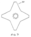
- Figure 7 is a plan view of another venturi spacer for use with the venturi insulators shown in of Figure 3, 4, and 5.
- Figure 8 is a plan view of an alternative embodiment of the deflector shown in Figure 3.
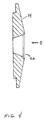
- Figure 9 is a cross-sectional view taken along section line 9-9' in Figure 8.
- Figure 10 is a cross-sectional view taken along section line 10-10' in Figure 8.
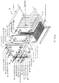
- Figure 11 is an exploded isometric view of an ionizer/collector cell of an electrostatic precipitator, including several venturi insulators.
- Figure 12 is an isometric view of an electrostatic precipitator utilizing several venturi insulators with air recirculation.
- FIG 3 illustrates one embodiment of a venturi insulator 24 arranged on a high voltage plate tie rod 12.
- Venturi insulator 24 may also be referred to as venturi-tube insulator 24 or venturi insulator disk 24.
- venturi insulator 24 is illustrated in the figures as being a round disk, it may also be formed in other shapes such as square, octagonal, or oval.
- Venturi insulator 24 may be formed from any electrically insulating material such as a thermoset glass filled polyester resin, ceramic, porcelain, or any other high voltage insulating material with good arc track resistance.
- the venturi insulator 24 includes a hole or passage 26 which is preferably near the center of venturi insulator 24 for receiving or supporting the high voltage tie rod 12.
- the hole 26 is large enough to provide a space between the high voltage tie rod 12 and the inside wall of hole 26 for allowing a fluid, such as air, to move through the space in the direction of flow B.
- This space allows flow B to exit hole 26 very near the surface of high voltage tie rod 12 so that the energy in flow B is not significantly dissipated before it contacts tie rod 12 after exiting hole 26.
- the velocity of flow B may be gradually increased as it enters hole 26 and increased again near the middle of hole 26 where the diameter becomes further reduced.
- the hole 26 may include a chamfer 28 at one or both ends for increasing the strength of the venturi insulator 24 near the end of the hole.
- the chamfer 28 also helps to redirect flow B as it exits the hole 26.
- a high energy and high velocity flow may thus be delivered to the surface of tie rod 12.
- a similar chamfer at the inlet to hole 26 may help to minimize energy loss during acceleration of flow B at the other end of hole 26.
- Hole 26 may therefore form a venturi or venturi-shaped passage.
- the venturi insulator 24 may be held on the high voltage tie rod 12 against an opening in end plate 2, or any other wall of the precipitator, by any conventional means such as by a tie rod secure nut 18. However, other fastening means such as cotter pins or adhesive bonding materials may be used to secure the venturi insulator 24 to the high voltage tie rod 12.
- the tie rod secure nut 18 and the end plate 2 may be received in recessed portions of the venturi insulator 24 to help keep the tie rod 12 centered inside the hole 26.
- the venturi insulator 24 may also be fastened directly to the end plate 2.
- the high voltage tie rod 12 may also be fitted with a venturi spacer 30 between the venturi insulator 24 and the tie rod secure nut 18.
- the venturi spacer 30 bridges the upstream opening of hole 26 and helps support and center the high voltage tie rod 12 inside the hole 26.
- the venturi spacer 30 also helps direct or guide the flow B through the hole in a direction which is parallel to the axis of hole 26.
- the venturi spacer 30 is preferably made from an insulating material such as a thermoset glass filled polyester resin or any other material which may be used to form the venturi insulator disk 24.
- a deflector 32 may be arranged on the high voltage plate tie rod 12 between the venturi insulator disk 24 and the tie rod secure nut 18.
- Figure 3 illustrates the deflector 32 including a tubular portion which may be slid over the high voltage tie rod 12.
- Deflector 32 may be used to deflect flow B as it exits hole 26.
- Deflector 32 may also increase the pressure, or create a positive fluid pressure, in the area around the inside face of the hole 26 by deflecting a portion of flow B perpendicular to the axis of the hole 26 when it exits the hole 26.
- the deflector 32 may be made from a high voltage insulating material with good arc track resistance.
- the tie rod 12 is shielded by the air stream deflector 32. Accordingly, the possibility of arc over between the tie rod 12 and the venturi insulator 24 is substantially reduced.
- the disk portion of the deflector 32 significantly increases the potential high voltage tracking distance.
- the deflection and/or increased pressure created by the deflector 32 causes the contaminant passing through the cell in the direction of flow A to be deflected away from the venturi insulator 24 and hole 26 and allows the face of venturi insulator 24 to remain clean. Consequently, the arc track distance between high voltage plate 8 and grounded end plate 2 may be maintained.
- the operating time between cleanings of the electrostatic precipitator can thus be significantly increased, especially when the precipitator is used with contaminants which are electrically conductive.
- the deflector 32 may also be referred to as an air stream deflector 32.
- Figures 4 and 5 illustrate cross-sections of alternative embodiments of the venturi insulator 24.
- the hole 26 has a decreasing diameter in the direction of flow B.
- the hole 26 in Figure 4 has a linearly decreasing diameter in the direction of flow B.
- the diameter of hole 26 could be also constant or decrease in a non-linear fashion.
- Figure 5 illustrates an embodiment of venturi insulator 24 wherein the diameter of hole 26 decreases in a curved or non-linear fashion.
- the generally decreasing diameter of hole 26 in Figure 5 gradually increases the velocity of flow B through venturi insulator 24 so that the flow B exiting the hole 26 achieves the greatest possible velocity with the least possible frictional losses inside the hole 26.
- the diameter of hole 26 near the outlet for flow B may slightly increase to gradually decelerate flow B near the outlet in order to minimize the turbulence and associated energy losses near the outlet.
- Hole 26 may therefore be a venturi or venturi-shaped passage.
- Figure 6 illustrates a plan view of one possible embodiment of the venturi spacer 30.
- Venturi spacer 30 helps center high voltage tie rod 12 in hole 26. Venturi spacer 30 may also guide or direct flow-B in a direction which is parallel to the axis of hole 26.
- the venturi spacer 30 of Figure 6 is cross-shaped with rounded corners near the intersection of the arms of the cross for increasing the strength of the spacer.
- An alternative embodiment of the venturi spacer 30 is illustrated in Figure 7.
- Figure 7 illustrates a star-shaped venturi spacer 30. The star-shape illustrated in Figure 7 may allow more air to pass into the hole 26 between the arms of the star.
- venturi spacer 30 may include just two arms which extend in opposite directions for allowing the greatest amount of air to flow into the hole 26 while still supporting and centering the high voltage tie rod 12.
- the dashed lines in Figures 6 and 7 indicate recessed portions on one side of the venturi spacer 30 for receiving one end of deflector 32 as illustrated in Figure 3.
- Figure 8 illustrates a plan view of an alternative embodiment of a the deflector 32 in relation to flow A.
- one side of the surface of deflector 32 may be curved while the other side is flat.
- the curved side of air stream deflector 32 is preferably arranged to face the exit of venturi hole 26 against flow B. Due to the restricted diameter between the curved surface of the deflector 32 and the venturi insulator 24, the velocity of flow A should increase between the deflector 32 and the venturi insulator 24 as it flows over the curved surface of the deflector 32 near the exit of hole 26. This increased velocity of air stream A near the exit of the hole 26 serves to increase the cleaning effect of the flow near the exit of hole 26.
- Other alternatives might include a square or rectangularly shaped disk portion of the deflector 32.
- FIG 11 is an exploded isometric view of an ionizer/collector cell compartment of an electrostatic precipitator including several venturi insulator disks 24.
- corona wires 4 have been replaced with quadrangle spiked ionizer plates 34 and ground electrodes 36.
- Several ionizer tie rods 38 secure quadrangle spiked ionizer plates 34 between end plates 2.
- An upper pressurized air transfer tube 40 and a lower pressurized air transfer tube 42 are arranged through the ground electrodes 36 for transferring air to the center of two parallel cells as will be described in more detail below with reference to Figure 12.
- the upper and lower pressurized air transfer tubes 40, 42 may also serve to support ground electrodes 36. It has also been found useful to arrange deflectors 32 between the quadrangle spiked ionizer plates 34 and end plate 2 in the first stage.
- the second stage of the ionizer/collector cell illustrated in Figure 11 includes several ground plates 10 interspaced between high voltage plates 8.
- Several high voltage tie rods 12 secure the high voltage plates 8 between end plates 2 while several ground plate tie rods 14 secure the ground plates 10 between end plates 2.
- the ground plates 10 may be electrically connected to the grounded end plates 2 through ground plate tie rods 14. Consequently, the venturi insulators 24 are not required for ground plate tie rods 10.
- Tubular spacers 20 may be arranged on each of the tie rods for maintaining an appropriate distance between the plates.
- the tubular spacers 20 separating high voltage plates 8 and the tubular spacers 20 separating ground plates 10 may be formed from an electrically conductive material, such as aluminum which is noncorrosive, light weight, and inexpensive.
- the tubular spacers 20 which are arranged between the end plates 2 and the high voltage plates 8 are preferably formed from a nonconductive material, such as a thermoset glass filled polyester resin, or any other material which may be used for venturi insulator 24.
- Each tie rod may be secured to the end plates 2 by a tie rod secure nut 18.
- Tubular plungers 48 are provided to make high voltage contact from power supply high voltage contacts between ionizer/collector cells.
- Springs 44 are provided to load the tubular plungers 48 so as to ensure high voltage contact between the cells and/or power supply. Alternatively, springs 44 may have one end resting directly against tie rod secure nut 18.
- Figure 12 is an isometric view of an electrostatic precipitator utilizing several venturi insulators with air recirculation.
- the integrated unit in Figure 12 utilizes two ionizer/collector cells arranged in parallel. However, the integrated unit can be constructed to utilize a single cell, as well as two or more cells in parallel. Where multiple cells are used, any number of ionizer/collector cells may be stacked so that the height is controlled by the number and diameter of air transfer tubes incorporated within the cell assemblies.
- the integrated unit of Figure 12 is provided with a blower drive motor 50 and an airfoil blower 52 which pulls air into the unit through the ionizer/collector cells.
- the processed fluid is discharged from airfoil blower 52 into a pressurized plenum compartment 54.
- Part of the processed air from the pressurized plenum compartment 54 may be ducted, or channeled, through a front return air duct 56 and rear return air duct 58 to front and rear bulkhead pressurized chambers 60, 62, respectively
- the remainder of the clean processed air may be discharged out of the rear of the unit through exhaust grill 64.
- a difference in pressure between the ionizer/collector cell chamber and the pressurized planum compartment 54 is created by the airfoil blower 52. That difference is sufficient to create an airflow through the venturi insulator disks 24.
- venturi insulators 24 preferably air which is processed by the precipitator, or clean air from another source, should be delivered to venturi insulators 24 in order to operate the precipitator for extended periods of time.
- the passage of any contaminant material into hole 26 in venturi insulator 24 may ultimately contribute to arc-over and shut down of the collecting system.
- the integrated unit of Figure 12 is therefore constructed so that flow B through the venturi insulator disks 24 may be provided from three different sources depending on the particular contaminant being collected.
- clean air may be recirculated from pressurized plenum compartment 54 to the venturi insulators 24 via front and rear air return ducts 56, 58.
- an auxiliary plate 70 may cover an external air port 68 in the front return duct 56 in order to prevent outside air from entering during normal recirculation operation.
- the front and rear air return ducts 56, 58 may be closed to recirculated air and outside air may be drawn into the front and rear air return ducts 56, 58 through the external air port 68.
- the air being process through the precipitator contains conductive particles, such as carbon
- conductive particles such as carbon
- the outside air may be pressurized or it may be drawn into the precipitator cell as a result of a low pressure created in the cell by the blower 52.
- auxiliary plate 70 may be hinged, or louvered, to allow external air port 68 to open only when outside air is needed or to allow a mixture of recirculated and clean air to be created in the return air ducts.
Landscapes
- Electrostatic Separation (AREA)
Abstract
A device for use in an electrostatic precipitator including an electrically insulating disk having a hole, which may be a venturi-shaped passage, for receiving a tie rod and an arrangement for supporting the tie rod in the hole so as to allow a fluid to flow through the hole between an inside surface of the hole and the tie rod. An air stream deflector may be mounted on the tie rod to provide further protection and help direct air flow. A recirculating flow system may also be provided to direct clean air through the venturi-shaped passage.
Description
- The present invention relates to electrical precipitators of the electrostatic type. In particular, the invention relates to an insulator for use in an electrostatic precipitator.
- Electrostatic precipitators are used to remove contaminants, such as liquid droplets and solid particles, from a fluid in which they are suspended. The precipitation process typically includes at least two basic steps. First, the contaminated suspension is ionized by passing it through an electrical corona. The ions produced in the fluid then collide with the suspended contaminant and cause the droplets and particles to become electrically charged. The ionized fluid with the charged contaminant particles is then passed through an electrostatic field where the charged particles are urged out of the fluid by a Coulombic force. The practical aspects of electrostatic precipitation, also referred to as electrodeposition or electro-precipitation, were first demonstrated on a commercial scale in the United States by Cottrell in 1906 and further developed by Penny in 1936.
- Figure 1 schematically illustrates a cross-section of a known two-stage electrostatic precipitator. A contaminated gaseous fluid, such as air or industrial effluent, flows in the direction of arrow A into one end of a duct formed by end plates 2. In the first stage of the precipitator, the contaminated fluid flows between
corona wires 4. Thecorona wires 4 are provided with a voltage that is sufficient to create an electrical corona around the wires. The fluid passing through the corona is ionized and contaminant particles in the fluid become charged by ion bombardment. - Further downstream in the direction of flow A, the second stage of the precipitator includes a series of
high voltage plates 8 interspaced betweenground plates 10. The ionized fluid with the charged contaminant particles flows into the gaps between the plates. The charged particles in the fluid are deposited on theplates 10 so that clean gas is expelled from the downstream end of the duct. - The
high voltage plates 8 are electrically connected and supported between the end plates 2 on a highvoltage tie rod 12. Similarly, theground plates 10 are connected and supported between end plates 2 on a separate groundplate tie rod 14. The end plates 2 forming the walls of a fluid duct are preferably grounded in order to reduce the electrical shock hazard posed bycorona wires 4 andhigh voltage plates 8. Furthermore, theground plates 10, the groundplate tie rod 14, and the end plates 2 may be grounded together through the same circuit. Consequently, the high voltageplate tie rod 12 and thehigh voltage plates 8 must be electrically insulated from the grounded end plates 2. - Figure 2 illustrates a conventional technique for insulating a
high voltage plate 8 from a grounded end plate 2. The high voltageplate tie rod 12 extends through aninsulator 16 which is held against end plate 2 on high voltageplate tie rod 12. The high voltageplate tie rod 12 may be threaded on each end and bolted to theinsulator 16 by a tie rodsecure nut 18.Insulator 16 is made from an electrically insulating material, such as ceramic or plastic, which inhibits current from flowing through thetie rod 12 to grounded end plate 2. A cylindrical or tubular spacer 20 may be arranged on thetie rod 12 in order to maintain the spacing between thehigh voltage plate 8 and theinsulator 16. Similar tubular spacers 20 may be arranged between each of thehigh voltage plates 8. - During normal operation of the device illustrated in Figure 2, the surfaces of
high voltage plate 8, tubular spacer 20, andinsulator 16 may become coated with a contaminant layer 22 which is deposited from flow A. If flow A contains a contaminant material which is electrically conductive, then contaminant layer 22 may eventually build up enough to provide an electrical path for a short circuit current fromhigh voltage plate 8 to grounded end plate 2. This condition is sometimes referred to as "arc-over." Once thehigh voltage plate 8 has been short circuited, the plate and in fact the entire collector section of said precipitator will no longer function to remove contaminant material from flow A as it passes by theplate 8 and through the collector plates of said precipitator. Actually, with positive ionization, particles first accumulate on ground plates. However, some accumulation occurs on high voltage spacers by impaction, which also adds to arc-over. Consequently, the precipitator of Figure 2 must frequently be taken out of service so that contaminant layer 22 may be cleaned from the surface ofinsulator 16 in order to prevent arc-over. - U.S. Patent No. 3,531,918 to Vegeby relates to a device for protecting tubular high voltage insulators in electrostatic precipitators against both dust coatings and condensation of vapors. This patent discloses a rod (8) which is supported by a plate (2) arranged at one end of a cylindrical high voltage insulator (1). The rod is used to suspend a known emission system including an unnamed element (7).
- The plate is provided with one or more large holes (3) having a constant diameter for rendering it possible to clean the interior of the insulator. A disk (14) is mounted above the plate and perforated with small holes (14a). Chamber (11) is provided with means for the supply of a compressed ventilation air or cleaned gas as protective medium, which is caused to flow downward through the small and large holes. According to Vegeby, a suitable quantity of flash gas with a relatively low pressure drop may be obtained through the small holes so that a low and uniform flowrate is thus obtained in the entire space within the cylindrical insulator and the cylindric shielding cylinder (5). Therefore, turbulence is avoided.
- The Vegeby apparatus has several shortcomings which may be overcome with the present invention. The first of these drawbacks is that the Vegeby device appears to require a continuous injection of compressed fluid for proper operation. Another drawback is that a dead space of air is created between the rod and the hole in the plate through which the rod extends. This dead space may become filled with contaminant material which then reduces the overall insulative effect of the device. Furthermore, this dead space is very difficult to clean without dismantling the entire apparatus. Moreover, the large holes in the disk are arranged far enough from the outer circumference of the rod that the velocity, and cleaning effect, of any gas which moves through the holes will be greatly reduced before it arrives at the surface of the rod. In fact, Vegeby actually encourages using low velocity airflow inside the cylindrical insulator in order to prevent turbulence. Finally, a significant amount of energy will be lost by the Vegeby gas when it is flashed, or throttled, across the small and large holes. Although these energy losses can be reduced by minimizing the velocity of the gas through the holes, higher velocity gases are preferred for keeping the rod clean.
- The present disclosure relates to a device for use in an electrostatic precipitator including an electrically insulating disk having a hole for receiving a tie rod and means for supporting said tie rod in said hole so as to allow a fluid to flow through said hole between an inside surface of said hole and said tie rod. The hole may form a venturi-shaped passage. The venturi-shaped passage may have a diameter that increases in a direction of said fluid flow at an outlet of said venturi-shaped passage. The venturi-shaped passage may also have a diameter that decreases in said direction of said fluid flow at an inlet of said passage. The supporting means may include a spacer for centering said tie rod in said hole. The spacer may be a venturi spacer for guiding said fluid to flow into said hole in a direction which is parallel to an axis of said hole. The device may further include a deflector arranged on said tie rod for deflecting said flow of fluid as it exits said hole. The deflector may have a curved surface facing said hole. The disk may be arranged with one side parallel to and in contact with a flow of fluid through said precipitator. The fluid may include fluid which has been processed by said precipitator.
- The disclosure also relates to a device for use in an electrostatic precipitator including an electrically insulating disk having a venturi-shaped passage for receiving a tie rod, means for supporting and centering said tie rod in said passage so as to allow a fluid to flow through said passage between an inside surface of said passage and said tie rod, and a deflector arranged on said tie rod for deflecting said flow of fluid as it exits said hole. The venturi-shaped passage may have a diameter that decreases in said direction of flow. The supporting and centering means may include a venturi spacer for guiding said fluid to flow into said passage in a direction which is parallel to an axis of said hole. The deflector may have a curved surface facing said hole. The disk may be arranged with one side parallel to and in contact with a flow of fluid through said precipitator. The fluid may include fluid which has been processed by said precipitator.
- The present disclosure also relates to a device for use in an electrostatic precipitator including an electrically insulating disk having a venturi-shaped passage for receiving a tie rod, means for supporting and centering said tie rod in said passage so as to allow a fluid to flow through said passage between an inside surface of said passage and said tie rod, and a deflector arranged on said tie rod for deflecting said flow of fluid as it exits said passage; said venturi-shaped passage having a diameter that decreases in a direction of said flow at an inlet of said passage and then increases in a direction of said flow at an outlet of said passage. The deflector may have a curved surface facing said hole. The disk may be arranged with one side parallel to and in contact with a flow of fluid through said precipitator. The fluid may include fluid which has been processed by said precipitator.
- The present disclosure also relates to a method of operating an electrostatic precipitator, including an electrically insulating disk having a hole for receiving a tie rod, including the step of flowing a fluid through said hole between an inside surface of said hole and said tie rod. The fluid may include fluid which has been processed by said precipitator.
- The invention will now be further described with reference to the following figures wherein the term "Figure" has been abbreviated as "Fig." and wherein like elements have been provided with the same reference numerals.
- Figure 1 is a schematic cross-sectional view of an electrostatic precipitator.
- Figure 2 is a cross-sectional view of one portion of an electrostatic precipitator showing an insulator.
- Figure 3 is a cross-sectional view of one portion of an electrostatic precipitator showing one embodiment of a venturi insulator.
- Figures 4 and 5 are cross-sectional views of venturi insulators for use in the electrostatic precipitator of Figure 3.
- Figure 6 is a plan view of a venturi spacer for use with the venturi insulators shown in Figures 3, 4, and 5.
- Figure 7 is a plan view of another venturi spacer for use with the venturi insulators shown in of Figure 3, 4, and 5.
- Figure 8 is a plan view of an alternative embodiment of the deflector shown in Figure 3.
- Figure 9 is a cross-sectional view taken along section line 9-9' in Figure 8.
- Figure 10 is a cross-sectional view taken along section line 10-10' in Figure 8.
- Figure 11 is an exploded isometric view of an ionizer/collector cell of an electrostatic precipitator, including several venturi insulators.
- Figure 12 is an isometric view of an electrostatic precipitator utilizing several venturi insulators with air recirculation.
- Figure 3 illustrates one embodiment of a
venturi insulator 24 arranged on a high voltageplate tie rod 12.Venturi insulator 24 may also be referred to as venturi-tube insulator 24 orventuri insulator disk 24. Althoughventuri insulator 24 is illustrated in the figures as being a round disk, it may also be formed in other shapes such as square, octagonal, or oval.Venturi insulator 24 may be formed from any electrically insulating material such as a thermoset glass filled polyester resin, ceramic, porcelain, or any other high voltage insulating material with good arc track resistance. - The
venturi insulator 24 includes a hole orpassage 26 which is preferably near the center ofventuri insulator 24 for receiving or supporting the highvoltage tie rod 12. Thehole 26 is large enough to provide a space between the highvoltage tie rod 12 and the inside wall ofhole 26 for allowing a fluid, such as air, to move through the space in the direction of flow B. This space allows flow B to exithole 26 very near the surface of highvoltage tie rod 12 so that the energy in flow B is not significantly dissipated before it contacts tierod 12 after exitinghole 26. Furthermore, there is no dead space between highvoltage tie rod 12 andinsulator 24 that could otherwise fill with contaminant. The velocity of flow B may be gradually increased as it entershole 26 and increased again near the middle ofhole 26 where the diameter becomes further reduced. - The
hole 26 may include achamfer 28 at one or both ends for increasing the strength of theventuri insulator 24 near the end of the hole. Thechamfer 28 also helps to redirect flow B as it exits thehole 26. A high energy and high velocity flow may thus be delivered to the surface oftie rod 12. A similar chamfer at the inlet to hole 26 may help to minimize energy loss during acceleration of flow B at the other end ofhole 26.Hole 26 may therefore form a venturi or venturi-shaped passage. - The
venturi insulator 24 may be held on the highvoltage tie rod 12 against an opening in end plate 2, or any other wall of the precipitator, by any conventional means such as by a tie rodsecure nut 18. However, other fastening means such as cotter pins or adhesive bonding materials may be used to secure theventuri insulator 24 to the highvoltage tie rod 12. The tie rodsecure nut 18 and the end plate 2 may be received in recessed portions of theventuri insulator 24 to help keep thetie rod 12 centered inside thehole 26. Theventuri insulator 24 may also be fastened directly to the end plate 2. - The high
voltage tie rod 12 may also be fitted with aventuri spacer 30 between theventuri insulator 24 and the tie rodsecure nut 18. Theventuri spacer 30 bridges the upstream opening ofhole 26 and helps support and center the highvoltage tie rod 12 inside thehole 26. Theventuri spacer 30 also helps direct or guide the flow B through the hole in a direction which is parallel to the axis ofhole 26. Theventuri spacer 30 is preferably made from an insulating material such as a thermoset glass filled polyester resin or any other material which may be used to form theventuri insulator disk 24. - A
deflector 32 may be arranged on the high voltageplate tie rod 12 between theventuri insulator disk 24 and the tie rodsecure nut 18. Figure 3 illustrates thedeflector 32 including a tubular portion which may be slid over the highvoltage tie rod 12.Deflector 32 may be used to deflect flow B as it exitshole 26.Deflector 32 may also increase the pressure, or create a positive fluid pressure, in the area around the inside face of thehole 26 by deflecting a portion of flow B perpendicular to the axis of thehole 26 when it exits thehole 26. - The
deflector 32 may be made from a high voltage insulating material with good arc track resistance. Thus, thetie rod 12 is shielded by theair stream deflector 32. Accordingly, the possibility of arc over between thetie rod 12 and theventuri insulator 24 is substantially reduced. In addition, the disk portion of thedeflector 32 significantly increases the potential high voltage tracking distance. - The deflection and/or increased pressure created by the
deflector 32 causes the contaminant passing through the cell in the direction of flow A to be deflected away from theventuri insulator 24 andhole 26 and allows the face ofventuri insulator 24 to remain clean. Consequently, the arc track distance betweenhigh voltage plate 8 and grounded end plate 2 may be maintained. The operating time between cleanings of the electrostatic precipitator can thus be significantly increased, especially when the precipitator is used with contaminants which are electrically conductive. Thedeflector 32 may also be referred to as anair stream deflector 32. - Figures 4 and 5 illustrate cross-sections of alternative embodiments of the
venturi insulator 24. In Figure 4, thehole 26 has a decreasing diameter in the direction of flow B. Thehole 26 in Figure 4 has a linearly decreasing diameter in the direction of flow B. However, the diameter ofhole 26 could be also constant or decrease in a non-linear fashion. - Figure 5 illustrates an embodiment of
venturi insulator 24 wherein the diameter ofhole 26 decreases in a curved or non-linear fashion. The generally decreasing diameter ofhole 26 in Figure 5 gradually increases the velocity of flow B throughventuri insulator 24 so that the flow B exiting thehole 26 achieves the greatest possible velocity with the least possible frictional losses inside thehole 26. The diameter ofhole 26 near the outlet for flow B may slightly increase to gradually decelerate flow B near the outlet in order to minimize the turbulence and associated energy losses near the outlet.Hole 26 may therefore be a venturi or venturi-shaped passage. - Figure 6 illustrates a plan view of one possible embodiment of the
venturi spacer 30.Venturi spacer 30 helps center highvoltage tie rod 12 inhole 26.Venturi spacer 30 may also guide or direct flow-B in a direction which is parallel to the axis ofhole 26. Theventuri spacer 30 of Figure 6 is cross-shaped with rounded corners near the intersection of the arms of the cross for increasing the strength of the spacer. An alternative embodiment of theventuri spacer 30 is illustrated in Figure 7. Figure 7 illustrates a star-shapedventuri spacer 30. The star-shape illustrated in Figure 7 may allow more air to pass into thehole 26 between the arms of the star. - Although each of the shapes in Figure 7 has been shown with four arms, a greater or lesser number of arms may also be used. For example, the
venturi spacer 30 may include just two arms which extend in opposite directions for allowing the greatest amount of air to flow into thehole 26 while still supporting and centering the highvoltage tie rod 12. The dashed lines in Figures 6 and 7 indicate recessed portions on one side of theventuri spacer 30 for receiving one end ofdeflector 32 as illustrated in Figure 3. - Figure 8 illustrates a plan view of an alternative embodiment of a the
deflector 32 in relation to flow A. As illustrated in the cross-sections of Figures 9 and 10, one side of the surface ofdeflector 32 may be curved while the other side is flat. The curved side ofair stream deflector 32 is preferably arranged to face the exit ofventuri hole 26 against flow B. Due to the restricted diameter between the curved surface of thedeflector 32 and theventuri insulator 24, the velocity of flow A should increase between thedeflector 32 and theventuri insulator 24 as it flows over the curved surface of thedeflector 32 near the exit ofhole 26. This increased velocity of air stream A near the exit of thehole 26 serves to increase the cleaning effect of the flow near the exit ofhole 26. Other alternatives might include a square or rectangularly shaped disk portion of thedeflector 32. - Figure 11 is an exploded isometric view of an ionizer/collector cell compartment of an electrostatic precipitator including several
venturi insulator disks 24. In the first stage of the cell illustrated in Figure 1,corona wires 4 have been replaced with quadrangle spikedionizer plates 34 andground electrodes 36. Several ionizer tie rods 38 secure quadrangle spikedionizer plates 34 between end plates 2. An upper pressurized air transfer tube 40 and a lower pressurized air transfer tube 42 are arranged through theground electrodes 36 for transferring air to the center of two parallel cells as will be described in more detail below with reference to Figure 12. The upper and lower pressurized air transfer tubes 40, 42 may also serve to supportground electrodes 36. It has also been found useful to arrangedeflectors 32 between the quadrangle spikedionizer plates 34 and end plate 2 in the first stage. - The second stage of the ionizer/collector cell illustrated in Figure 11 includes
several ground plates 10 interspaced betweenhigh voltage plates 8. Several highvoltage tie rods 12 secure thehigh voltage plates 8 between end plates 2 while several groundplate tie rods 14 secure theground plates 10 between end plates 2. Theground plates 10 may be electrically connected to the grounded end plates 2 through groundplate tie rods 14. Consequently, theventuri insulators 24 are not required for groundplate tie rods 10. - Tubular spacers 20 may be arranged on each of the tie rods for maintaining an appropriate distance between the plates. The tubular spacers 20 separating
high voltage plates 8 and the tubular spacers 20 separatingground plates 10 may be formed from an electrically conductive material, such as aluminum which is noncorrosive, light weight, and inexpensive. The tubular spacers 20 which are arranged between the end plates 2 and thehigh voltage plates 8 are preferably formed from a nonconductive material, such as a thermoset glass filled polyester resin, or any other material which may be used forventuri insulator 24. - Each tie rod may be secured to the end plates 2 by a tie rod
secure nut 18. Tubular plungers 48 are provided to make high voltage contact from power supply high voltage contacts between ionizer/collector cells. Springs 44 are provided to load the tubular plungers 48 so as to ensure high voltage contact between the cells and/or power supply. Alternatively, springs 44 may have one end resting directly against tie rodsecure nut 18. - Figure 12 is an isometric view of an electrostatic precipitator utilizing several venturi insulators with air recirculation. The integrated unit in Figure 12 utilizes two ionizer/collector cells arranged in parallel. However, the integrated unit can be constructed to utilize a single cell, as well as two or more cells in parallel. Where multiple cells are used, any number of ionizer/collector cells may be stacked so that the height is controlled by the number and diameter of air transfer tubes incorporated within the cell assemblies.
- The integrated unit of Figure 12 is provided with a
blower drive motor 50 and anairfoil blower 52 which pulls air into the unit through the ionizer/collector cells. The processed fluid is discharged fromairfoil blower 52 into apressurized plenum compartment 54. Part of the processed air from thepressurized plenum compartment 54 may be ducted, or channeled, through a frontreturn air duct 56 and rear return air duct 58 to front and rear bulkhead pressurizedchambers 60, 62, respectively The remainder of the clean processed air may be discharged out of the rear of the unit throughexhaust grill 64. Once inside the bulkhead pressurizedchambers 60, 62, part of the cleaned air (i.e., flow B) moves throughholes 26 inventuri insulators 24 while the remainder of the air in the pressurized chambers goes into upper and lower pressurized air transfer tubes 40, 42. As illustrated in Figure 12, upper and lower pressurized air transfer tubes 40, 42 connect the bulkhead pressurized chambers with similar chambers formed near the center by the inboard cell end plates 66. Consequently, flow B may be supplied toventuri insulator disks 24 at each end of both ionizer/collector cells. - A difference in pressure between the ionizer/collector cell chamber and the
pressurized planum compartment 54 is created by theairfoil blower 52. That difference is sufficient to create an airflow through theventuri insulator disks 24. - It is has been found by the present inventors that preferably air which is processed by the precipitator, or clean air from another source, should be delivered to
venturi insulators 24 in order to operate the precipitator for extended periods of time. The passage of any contaminant material intohole 26 inventuri insulator 24 may ultimately contribute to arc-over and shut down of the collecting system. The integrated unit of Figure 12 is therefore constructed so that flow B through theventuri insulator disks 24 may be provided from three different sources depending on the particular contaminant being collected. - First, clean air may be recirculated from
pressurized plenum compartment 54 to theventuri insulators 24 via front and rearair return ducts 56, 58. In that mode, anauxiliary plate 70 may cover an external air port 68 in thefront return duct 56 in order to prevent outside air from entering during normal recirculation operation. Second, the front and rearair return ducts 56, 58 may be closed to recirculated air and outside air may be drawn into the front and rearair return ducts 56, 58 through the external air port 68. For example, if the air being process through the precipitator contains conductive particles, such as carbon, it may be preferable to use outside air introduced through the external air port 68 instead of the recirculated air, because residual conductive particles that were not removed during processing may cause premature arc overs. The outside air may be pressurized or it may be drawn into the precipitator cell as a result of a low pressure created in the cell by theblower 52. - Alternatively, the
auxiliary plate 70 may be hinged, or louvered, to allow external air port 68 to open only when outside air is needed or to allow a mixture of recirculated and clean air to be created in the return air ducts. - The principles, preferred embodiments, and modes of operation of the present invention have been described in the foregoing specification. However, the invention should not be construed as limited to the particular embodiments which have been described above. Instead, the embodiments described here should be regarded as illustrative rather than restrictive. Variations and changes may be made by others without departing from the scope of the invention as defined by the following claims.
Claims (10)
- A method of operating an electrostatic precipitator which includes an ionizing/collecting cell having an end plate (2), a tie rod (12), a high voltage plate (8) mounted on said tie rod within the cell and an electrically insulating disk (24) having a venturi shaped hole (26) for receiving the tie rod, said method comprising causing a contaminated fluid to flow through the cell and accelerating a cleaning fluid through said hole between the inside surface of said hole and said tie rod so as to clean contaminant precipitated from said contaminated fluid from said tie rod.
- A method of claim 1 wherein said cleaning fluid includes fluid which has been processed by said precipitator.
- A method of claim 1 or 2 wherein the cleaning fluid flows perpendicularly towards a high voltage plate.
- A method of any one of the preceding claims which includes the step of deflecting cleaning fluid after acceleration through the hole so as to deflect contaminant away from the hole.
- A method as claimed in any one of the preceding claims wherein the contaminated fluid is drawn out of the cell by establishing a reduced pressure therein.
- An electrostatic precipitator, comprising:an ionizing/collecting cell having an end plate (2);a tie rod (12);a high voltage plate (8) mounted on said tie rod within the cell;said end plate arranged parallel to said high voltage plate;an electrically insulating disk (24) mounted in said end plate, said disk having a passage (26) for receiving the tie rod;means for causing a contaminated fluid to flow through the cell;means for reducing the pressure inside said ionizing/collecting cell;means for supporting said tie rod in said passage so as to allow a cleaning fluid to flow through said passage between an inside surface of said passage and said tie rod, said cleaning fluid flow being directed toward said high voltage plate in a direction that is substantially perpendicular to said high voltage plate; andsaid passage including narrow venturi means at a side of the disk facing said cell for accelerating the flow of the cleaning fluid through the passage into the cell.
- A precipitator as claimed in claim 6, wherein said passage has a diameter that decreases in a direction of said flow.
- A precipitator as claimed in claim 7 or 8 further comprising a deflector on said tie rod for deflecting said flow of cleaning fluid after it exits said passage.
- A precipitator as claimed in any one of the preceding claims wherein said disk is arranged with one side parallel to and in contact with the flow of said contaminated fluid through said cell.
- A device as claimed in any one of the preceding claims wherein said cleaning fluid includes a second fluid which has been processed by said precipitator.
Applications Claiming Priority (3)
| Application Number | Priority Date | Filing Date | Title |
|---|---|---|---|
| US07/943,543 US5421863A (en) | 1992-09-11 | 1992-09-11 | Self-cleaning insulator for use in an electrostatic precipitator |
| US943543 | 1992-09-11 | ||
| EP93307164A EP0587441B1 (en) | 1992-09-11 | 1993-09-10 | Venturi insulator for use in an electrostatic precipitator |
Related Parent Applications (2)
| Application Number | Title | Priority Date | Filing Date |
|---|---|---|---|
| EP93307164A Division EP0587441B1 (en) | 1992-09-11 | 1993-09-10 | Venturi insulator for use in an electrostatic precipitator |
| EP93307164.9 Division | 1993-09-10 |
Publications (1)
| Publication Number | Publication Date |
|---|---|
| EP0775527A1 true EP0775527A1 (en) | 1997-05-28 |
Family
ID=25479838
Family Applications (2)
| Application Number | Title | Priority Date | Filing Date |
|---|---|---|---|
| EP93307164A Expired - Lifetime EP0587441B1 (en) | 1992-09-11 | 1993-09-10 | Venturi insulator for use in an electrostatic precipitator |
| EP97200339A Withdrawn EP0775527A1 (en) | 1992-09-11 | 1993-09-10 | Venturi insulator for use in an electrostatic precipitator |
Family Applications Before (1)
| Application Number | Title | Priority Date | Filing Date |
|---|---|---|---|
| EP93307164A Expired - Lifetime EP0587441B1 (en) | 1992-09-11 | 1993-09-10 | Venturi insulator for use in an electrostatic precipitator |
Country Status (4)
| Country | Link |
|---|---|
| US (1) | US5421863A (en) |
| EP (2) | EP0587441B1 (en) |
| AT (1) | ATE166255T1 (en) |
| DE (1) | DE69318655T2 (en) |
Cited By (5)
| Publication number | Priority date | Publication date | Assignee | Title |
|---|---|---|---|---|
| WO2006015504A1 (en) | 2004-08-11 | 2006-02-16 | Eidgenössische Materialprüfungs- und Forschungsanstalt Empa | Electric filter for a firing plant |
| WO2006015503A1 (en) * | 2004-08-11 | 2006-02-16 | Eidgenössische Materialprüfungs- und Forschungsanstalt Empa | Electric filter for a firing plant |
| DE102006003028A1 (en) * | 2006-01-20 | 2007-08-02 | Schmatloch Nückel Technologietransfer | Electric filter for firing plant, e.g. in private household, e.g. chimney oven, has filter electrode, housing, where electrode holder is arranged partially in housing, and surrounds circular screen in defined distance |
| CN109261359A (en) * | 2018-11-30 | 2019-01-25 | 东莞市启力致尚技术研发有限公司 | A kind of antifouling erecting by overhang of electrostatic dust collector cathode system |
| CN109550596A (en) * | 2018-11-30 | 2019-04-02 | 东莞市启力致尚技术研发有限公司 | A kind of antifouling work electrostatic precipitator |
Families Citing this family (26)
| Publication number | Priority date | Publication date | Assignee | Title |
|---|---|---|---|---|
| JP3191264B2 (en) * | 1997-02-27 | 2001-07-23 | ギャラクシー有限会社 | Electric dust collector and incinerator |
| KR100234085B1 (en) * | 1997-12-27 | 1999-12-15 | 윤종용 | Electrostatic precipitator |
| DE19946283C1 (en) * | 1999-07-31 | 2000-09-28 | Metallgesellschaft Ag | Earth conductor for earthing systems consists of conducting part on current source, earth sides connected via liquid-tight graphite part with attached unencased conducting part core sections |
| DE10227703B3 (en) * | 2002-06-21 | 2004-02-12 | Forschungszentrum Karlsruhe Gmbh | Feed-through for electrical high voltage through a wall that separates a surrounding area from a process area |
| DE10240354A1 (en) * | 2002-08-28 | 2004-03-11 | Siemens Ag | Disc insulator with a symmetrical outer contour |
| US20050045038A1 (en) * | 2003-09-03 | 2005-03-03 | Ping Huang | Frame structure of an electrostatic precipitator |
| US6958089B1 (en) * | 2004-06-29 | 2005-10-25 | Hung Hsing Electric Co., Ltd. | Structure of an electrostatic precipitator |
| US20070180996A1 (en) * | 2006-02-09 | 2007-08-09 | Oreck Holdings, Llc | Tower air cleaner with improved airflow |
| US7264659B1 (en) * | 2006-05-10 | 2007-09-04 | Moshenrose Paul A | Plate fastener for an electrostatic precipitator cell |
| DE102006057705B3 (en) * | 2006-12-07 | 2008-03-27 | Robert Bosch Gmbh | Energy generation heating system by combustion of energy source such as biomass for motor vehicle, has electrode feed coated with insulator and enclosing particle rejecting unit, which prevents exhaust gas particle deposition on insulator |
| US7361207B1 (en) * | 2007-02-28 | 2008-04-22 | Corning Incorporated | System and method for electrostatically depositing aerosol particles |
| DE102007028134B3 (en) * | 2007-06-19 | 2008-12-18 | Robert Bosch Gmbh | Electrostatic separator and heating system |
| JP5056499B2 (en) * | 2008-03-11 | 2012-10-24 | ダイキン工業株式会社 | Air treatment equipment |
| EP2276915A2 (en) * | 2008-03-25 | 2011-01-26 | Ogut, Ali | Non-thermal plasma particulate reduction systems and methods of use thereof |
| DE102008038236B4 (en) * | 2008-08-18 | 2011-07-21 | Robert Bosch GmbH, 70469 | An electrostatic precipitator and heating system comprising an electrode particle repellent comprising a bimetal |
| US9321055B2 (en) * | 2008-11-05 | 2016-04-26 | Fmc Technologies, Inc. | Gas electrostatic coalescer |
| CN101986119B (en) * | 2010-10-27 | 2012-08-15 | 西安交通大学 | Device and method for measuring furnace pressure in coal-fired boiler |
| PL2471602T3 (en) * | 2010-12-29 | 2014-05-30 | General Electric Technology Gmbh | Electrical screening device for structures near high voltage parts of electrostatic precipitators |
| WO2015034998A1 (en) * | 2013-09-05 | 2015-03-12 | Regal Beloit America, Inc. | Electrostatic blower for flue gas |
| US9808808B2 (en) * | 2014-09-12 | 2017-11-07 | University Of Washington | Electrostatic precipitator |
| KR102209792B1 (en) * | 2019-05-20 | 2021-01-29 | 두산중공업 주식회사 | Dust collecting tower |
| CN112474054B (en) * | 2020-11-09 | 2024-11-29 | 西安西矿环保科技有限公司 | Ash removal device of electric dust remover insulator inner wall |
| KR102484322B1 (en) * | 2021-04-14 | 2023-01-05 | 한국기계연구원 | Electric precipitation |
| WO2022220364A1 (en) * | 2021-04-14 | 2022-10-20 | 한국기계연구원 | Electric precipitator and dust collection plate fixing structure of electric precipitator |
| US12544770B2 (en) * | 2021-08-12 | 2026-02-10 | Exentec U.S., Inc. | Method and apparatus for cleaning an electrostatic precipitator gas scrubbing apparatus |
| EP4741062A1 (en) * | 2024-11-08 | 2026-05-13 | exodraft a/s | Electrostatic precipitator assembly |
Citations (4)
| Publication number | Priority date | Publication date | Assignee | Title |
|---|---|---|---|---|
| DE328828C (en) * | 1920-01-01 | 1920-11-12 | Paul Kirchhoff Dipl Ing | Process and device for maintaining the insulation of insulators located in gases containing dust or moisture |
| DE505686C (en) * | 1925-12-23 | 1930-08-23 | Siemens Schuckertwerke Akt Ges | Device for preventing dust deposits on the insulators of electrical gas cleaners |
| FR1176956A (en) * | 1957-04-11 | 1959-04-17 | Centre Nat Rech Scient | Simple type of electric dust collector |
| DE1093447B (en) * | 1959-07-28 | 1960-11-24 | Metallgesellschaft Ag | Device for preventing the formation of eddies leading to pollution during the ventilation of insulators in electrical gas cleaning or emulsion separation systems |
Family Cites Families (17)
| Publication number | Priority date | Publication date | Assignee | Title |
|---|---|---|---|---|
| CH224043A (en) * | 1942-02-05 | 1942-10-31 | Porzellanfabrik Langenthal A G | Isolator on electrical dust extractors. |
| US2535696A (en) * | 1947-06-28 | 1950-12-26 | Westinghouse Electric Corp | Electrostatic precipitator |
| CH453450A (en) * | 1964-12-17 | 1968-06-14 | Schloz Motor Condensator | Pressure-tight high-voltage bushing, especially for a gas-filled electrostatic precipitator or flocculator |
| SE329596B (en) * | 1967-07-31 | 1970-10-19 | Svenska Flaektfabriken Ab | |
| ES381987A1 (en) * | 1969-08-29 | 1973-04-16 | Krupp Gmbh | Electrofilter insulator without damaging dust deposits |
| US3581470A (en) * | 1969-12-30 | 1971-06-01 | Emerson Electric Co | Electronic air cleaning cell |
| US3707828A (en) * | 1970-06-24 | 1973-01-02 | Westinghouse Electric Corp | Precipitator cell |
| US3788041A (en) * | 1972-09-13 | 1974-01-29 | Gaylord Ind | Electrostatic precipitator for high temperature operation |
| US3985525A (en) * | 1973-03-06 | 1976-10-12 | Chemtool, Inc. | Electrostatic air cleaner |
| US4018578A (en) * | 1975-05-01 | 1977-04-19 | Ahlrich Willard K | Electrostatic precipitator |
| JPS5260476A (en) * | 1975-11-13 | 1977-05-18 | Nippon Kokan Kk <Nkk> | Air purging device for insulators of electric dust collectors |
| US4117255A (en) * | 1976-04-30 | 1978-09-26 | Hitachi Plant Engineering & Construction | Insulator bushing for high voltage input |
| US4373937A (en) * | 1977-09-30 | 1983-02-15 | Emerson Electric Co. | Electrostatic precipitator with modular cabinet and cell washer |
| GB2046132B (en) * | 1979-04-02 | 1983-02-09 | Environmental Elements Corp | Protector tube for high voltage suspension insulator of an electro-static precipitator |
| US4294591A (en) * | 1980-05-12 | 1981-10-13 | Envirotech Corporation | Mounting for high-voltage electrode support frame in an electrostatic precipitator |
| DE3511059A1 (en) * | 1985-03-27 | 1986-10-02 | Metallgesellschaft Ag, 6000 Frankfurt | INSULATION DEVICE |
| JPH0696131B2 (en) * | 1986-10-14 | 1994-11-30 | 三菱重工業株式会社 | Electrostatic precipitator electrode support device |
-
1992
- 1992-09-11 US US07/943,543 patent/US5421863A/en not_active Expired - Fee Related
-
1993
- 1993-09-10 EP EP93307164A patent/EP0587441B1/en not_active Expired - Lifetime
- 1993-09-10 EP EP97200339A patent/EP0775527A1/en not_active Withdrawn
- 1993-09-10 AT AT93307164T patent/ATE166255T1/en not_active IP Right Cessation
- 1993-09-10 DE DE69318655T patent/DE69318655T2/en not_active Expired - Fee Related
Patent Citations (4)
| Publication number | Priority date | Publication date | Assignee | Title |
|---|---|---|---|---|
| DE328828C (en) * | 1920-01-01 | 1920-11-12 | Paul Kirchhoff Dipl Ing | Process and device for maintaining the insulation of insulators located in gases containing dust or moisture |
| DE505686C (en) * | 1925-12-23 | 1930-08-23 | Siemens Schuckertwerke Akt Ges | Device for preventing dust deposits on the insulators of electrical gas cleaners |
| FR1176956A (en) * | 1957-04-11 | 1959-04-17 | Centre Nat Rech Scient | Simple type of electric dust collector |
| DE1093447B (en) * | 1959-07-28 | 1960-11-24 | Metallgesellschaft Ag | Device for preventing the formation of eddies leading to pollution during the ventilation of insulators in electrical gas cleaning or emulsion separation systems |
Cited By (7)
| Publication number | Priority date | Publication date | Assignee | Title |
|---|---|---|---|---|
| WO2006015504A1 (en) | 2004-08-11 | 2006-02-16 | Eidgenössische Materialprüfungs- und Forschungsanstalt Empa | Electric filter for a firing plant |
| WO2006015503A1 (en) * | 2004-08-11 | 2006-02-16 | Eidgenössische Materialprüfungs- und Forschungsanstalt Empa | Electric filter for a firing plant |
| DE102006003028A1 (en) * | 2006-01-20 | 2007-08-02 | Schmatloch Nückel Technologietransfer | Electric filter for firing plant, e.g. in private household, e.g. chimney oven, has filter electrode, housing, where electrode holder is arranged partially in housing, and surrounds circular screen in defined distance |
| DE102006003028B4 (en) * | 2006-01-20 | 2008-02-07 | Schmatloch Nückel Technologietransfer | Electrostatic precipitator with self-cleaning device for a furnace and method for operating the electrostatic precipitator |
| CN109261359A (en) * | 2018-11-30 | 2019-01-25 | 东莞市启力致尚技术研发有限公司 | A kind of antifouling erecting by overhang of electrostatic dust collector cathode system |
| CN109550596A (en) * | 2018-11-30 | 2019-04-02 | 东莞市启力致尚技术研发有限公司 | A kind of antifouling work electrostatic precipitator |
| CN109261359B (en) * | 2018-11-30 | 2020-06-19 | 南京溧水高新创业投资管理有限公司 | Antifouling hanging device of electrostatic precipitator negative pole system |
Also Published As
| Publication number | Publication date |
|---|---|
| US5421863A (en) | 1995-06-06 |
| DE69318655D1 (en) | 1998-06-25 |
| ATE166255T1 (en) | 1998-06-15 |
| EP0587441A1 (en) | 1994-03-16 |
| DE69318655T2 (en) | 1998-11-26 |
| EP0587441B1 (en) | 1998-05-20 |
Similar Documents
| Publication | Publication Date | Title |
|---|---|---|
| EP0587441B1 (en) | Venturi insulator for use in an electrostatic precipitator | |
| US6228149B1 (en) | Method and apparatus for moving, filtering and ionizing air | |
| US5395430A (en) | Electrostatic precipitator assembly | |
| US6004376A (en) | Method for the electrical charging and separation of particles that are difficult to separate from a gas flow | |
| US5084077A (en) | Apparatus for gas purification | |
| US4194888A (en) | Electrostatic precipitator | |
| US4216000A (en) | Resistive anode for corona discharge devices | |
| US20040025497A1 (en) | Electrostatic filter | |
| US3740927A (en) | Electrostatic precipitator | |
| US4692174A (en) | Ionizer assembly having a bell-mouth outlet | |
| US4861356A (en) | Close-spaced electrostatic precipitator | |
| EP3871779A1 (en) | Air dust removal system and method | |
| US4449159A (en) | Focusing electrodes for high-intensity ionizer stage of electrostatic precipitator | |
| US5147423A (en) | Corona electrode for electrically charging aerosol particles | |
| EP0076798B1 (en) | Electrostatic precipitator having high strength discharge electrode | |
| CA1083497A (en) | Vaned anode or high-intensity ionizer stage of electrostatic precipitator | |
| US4364752A (en) | Electrostatic precipitator apparatus having an improved ion generating means | |
| US4940471A (en) | Device for cleaning two-stage electrostatic precipitators | |
| US5909813A (en) | Force field separator | |
| CA1102257A (en) | Focusing electrodes for high-intensity ionizer stage of electrostatic precipitator | |
| EP0019464B1 (en) | Apparatus for charging particles in a gas stream and collecting the particles therefrom | |
| KR102282045B1 (en) | Energy-saving two-way electric dust collector that adjusts the supply voltage according to the concentration of dust | |
| KR102883461B1 (en) | Blower for indoor ventilation including a central exhaust type inlet having an electric dust collection function | |
| EP4596108A1 (en) | An electrostatic precipitator and an electro-cyclone separator comprising an electrostatic precipitator | |
| US8500873B2 (en) | Physical structure of exhaust-gas cleaning installations |
Legal Events
| Date | Code | Title | Description |
|---|---|---|---|
| PUAI | Public reference made under article 153(3) epc to a published international application that has entered the european phase |
Free format text: ORIGINAL CODE: 0009012 |
|
| 17P | Request for examination filed |
Effective date: 19970207 |
|
| AC | Divisional application: reference to earlier application |
Ref document number: 587441 Country of ref document: EP |
|
| AK | Designated contracting states |
Kind code of ref document: A1 Designated state(s): CH DE FR GB LI |
|
| 17Q | First examination report despatched |
Effective date: 19980709 |
|
| STAA | Information on the status of an ep patent application or granted ep patent |
Free format text: STATUS: THE APPLICATION IS DEEMED TO BE WITHDRAWN |
|
| 18D | Application deemed to be withdrawn |
Effective date: 19981120 |