EP0774355A2 - Ink jet apparatus - Google Patents
Ink jet apparatus Download PDFInfo
- Publication number
- EP0774355A2 EP0774355A2 EP97101749A EP97101749A EP0774355A2 EP 0774355 A2 EP0774355 A2 EP 0774355A2 EP 97101749 A EP97101749 A EP 97101749A EP 97101749 A EP97101749 A EP 97101749A EP 0774355 A2 EP0774355 A2 EP 0774355A2
- Authority
- EP
- European Patent Office
- Prior art keywords
- ink
- manifold
- ink chambers
- chambers
- plate
- Prior art date
- Legal status (The legal status is an assumption and is not a legal conclusion. Google has not performed a legal analysis and makes no representation as to the accuracy of the status listed.)
- Granted
Links
Images


Classifications
-
- B—PERFORMING OPERATIONS; TRANSPORTING
- B41—PRINTING; LINING MACHINES; TYPEWRITERS; STAMPS
- B41J—TYPEWRITERS; SELECTIVE PRINTING MECHANISMS, i.e. MECHANISMS PRINTING OTHERWISE THAN FROM A FORME; CORRECTION OF TYPOGRAPHICAL ERRORS
- B41J2/00—Typewriters or selective printing mechanisms characterised by the printing or marking process for which they are designed
- B41J2/005—Typewriters or selective printing mechanisms characterised by the printing or marking process for which they are designed characterised by bringing liquid or particles selectively into contact with a printing material
- B41J2/01—Ink jet
- B41J2/135—Nozzles
- B41J2/14—Structure thereof only for on-demand ink jet heads
- B41J2/14201—Structure of print heads with piezoelectric elements
- B41J2/14209—Structure of print heads with piezoelectric elements of finger type, chamber walls consisting integrally of piezoelectric material
Landscapes
- Particle Formation And Scattering Control In Inkjet Printers (AREA)
Abstract
Description
- The present invention relates to an ink jet apparatus that prints by ejecting ink droplets under pressure from nozzles.
- Traditional impact printers are now being replaced with non-impact printers, and the market of the non-impact printers is being expanded. One known kind of non-impact printers is an ink jet printer simple in principle and that can easily effect multi-scale or color printing. Of all of the types of ink jet printers, a drop-on-demand type ink jet printer capable of jetting ink droplets at a required time during printing has rapidly spread owing to its good jetting efficiency and its low running cost.
- Typical examples of such drop-on-demand type ink jet printers, are a Kaiser type disclosed in Japanese Patent Publication No. Sho 53-12138 and a thermal jet type disclosed in Japanese Patent Publication No. Sho 61-59914, for example. However, the former is hard to reduce in size, and the latter is required to have a high heat resistance of ink because the ink undergoes a high temperature. Thus, both types have very severe problems in application.
- To solve the above problems, there has been a newly proposed shear mode type disclosed in U.S. Patent No. 4,887,100, for example.
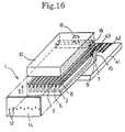
- Fig. 16 shows a shear mode type
ink jet apparatus 1 in the prior art. As shown in Fig. 16, theink jet apparatus 1 is constructed of apiezoelectric ceramics plate 2, acover plate 10, anozzle plate 14, and asubstrate 41. - The
piezoelectric ceramics plate 2 is provided with a plurality ofgrooves 3 by grinding with use of a diamond blade or the like. Accordingly, a plurality ofside walls 6 extend along thegrooves 3 in such a manner that eachside wall 6 is formed between adjacent ones of thegrooves 3. Eachside wall 6 is polarized in a direction indicated by anarrow 5. All thegrooves 3 have the same depth, and they are parallel to each other. The depth of eachgroove 3 is gradually reduced as it approaches arear end surface 15 of thepiezoelectric ceramics plate 2 to form a shallow groove 7 near therear end surface 15. A pair ofmetal electrodes 8 are formed on opposed side surfaces of eachgroove 3 at an upper half portion thereof by sputtering or the like. Further, ametal electrode 9 is formed on opposed side surfaces and a bottom surface of each shallow groove 7 by sputtering or the like. The pair ofmetal electrodes 8 formed on the opposed side surfaces of eachgroove 3 are connected with themetal electrode 9 formed on the opposed side surfaces and the bottom surface of the corresponding shallow groove 7 contiguous to thegroove 3. - The
cover plate 10 is formed of a ceramics material, a resin material, etc. Thecover plate 10 is provided with anink inlet hole 16 and amanifold 18 communicating with theink inlet hole 16 by grinding, cutting, etc. The lower surface of thecover plate 10, on which themanifold 18 is formed, is bonded to the upper surface of thepiezoelectric ceramics plate 2 on which thegrooves 3 are formed by an epoxy adhesive 20 (see Fig. 18). Accordingly, a plurality ofindividual ink chambers 4 functioning as ink channels (see Fig. 18) are defined by thegrooves 3 of thepiezoelectric ceramics plate 2 and the lower surface of thecover plate 10 to be transversely equally spaced from each other. As shown in Fig. 18, eachink chamber 4 is rectangular in vertical section, and it is filled with ink in operation. - As shown in Fig. 16, the
nozzle plate 14 is bonded to the front end surface of the assembly of thepiezoelectric ceramics plate 2 and thecover plate 10. Thenozzle plate 14 is provided with a plurality ofnozzles 12 at laterally spaced positions corresponding to the front end positions of theink chambers 4. Thenozzle plate 14 is formed of a plastic material such as polyalkylene terephthalate (e.g., polyethylene terephthalate), polyimide, polyetherimide, polyetherketone, polyethersulfone, polycarbonate, or cellulose acetate. - The
substrate 41 is bonded to the lower surface of thepiezoelectric ceramics plate 2 on the opposite side of thecover plate 10 by an adhesive such as an epoxy adhesive. A plurality of individualconductor film patterns 42 are formed on thesubstrate 41 at transversely spaced positions corresponding to the rear end positions of theink chambers 4. Eachconductor film pattern 42 is connected through aconductor wire 43 to themetal electrode 9 formed on the bottom surface of the shallow groove 7 in thecorresponding ink chamber 4 by wire bonding. - Fig. 17 shows a schematic diagram of a control section for controlling the
ink jet apparatus 1. As shown in Fig. 17, theconductor film patterns 42 formed on thesubstrate 41 are individually connected to anLSI chip 51. Also connected to theLSI chip 51 are aclock line 52, adata line 53, avoltage line 54, and aground line 55. TheLSI chip 51 determines from whichnozzle 12 the ink droplets are to be jetted according to data appearing on thedata dine 53 on the basis of continuous clock pulses supplied from theclock line 52. Then, according to the result of determination, theLSI chip 51 applies a voltage V of thevoltage line 54 to theconductor film pattern 42 connected to themetal electrode 8 in theink chamber 4 to be driven. Further, theLSI chip 51 applies a zero volt of theground line 55 to the otherconductor film patterns 42 connected to themetal electrodes 8 in theother ink chambers 4 not to be driven. - The operation of the
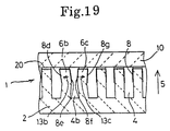
ink jet apparatus 1 is described with reference to Figs. 18 and 19. When theLSI chip 51 determines that the ink droplets are to be jetted from thenozzle 12 corresponding to theink chamber 4b as one of theink chambers 4 of theink jet apparatus 1 according to given data, a positive driving voltage V is applied to themetal electrodes metal electrodes arrow 13b is generated in theside wall 6b, and a driving electric field in a direction indicated by anarrow 13c is generated in theside wall 6c. As the directions indicated by thearrows arrow 5 of polarization of thepiezoelectric ceramics plate 2, theside walls ink chamber 4b by a piezoelectric thickness shear effect. This deformation of theside walls ink chamber 4b to rapidly increase the pressure of the ink filled in theink chamber 4b and thereby generate a pressure wave. As a result, the ink droplets are jetted from the nozzle 12 (see Fig. 19) communicating with theink chamber 4b. - When the application of the driving voltage V is stopped, the
side walls ink chamber 4b is therefore gradually decreased. Then, additional ink is supplied from an ink tank (not shown) through the ink inlet hole 16 (see Fig. 16) and the manifold 18 (see Fig. 16) into theink chamber 4b. - Referring to Fig. 14 for explanatory purposes, which is a sectional side view of the ink jet apparatus according to the invention, when the pressure in each
ink chamber 4 is increased to jet the ink droplets, the ink is forced from thecorresponding nozzle 12 simultaneously, the ink reversely flows from themanifold 18 into theink inlet hole 15. As a result, the pressure near themanifold 18 is rapidly reduced to generate a negative pressure wave. When this negative pressure wave reaches thenozzle 12, the ink jet from thenozzle 12 is stopped. The shorter the distance y between the front side surface of themanifold 18 and the inner surface of thenozzle plate 14, the shorter the time of reach of the negative pressure wave to thenozzle 12. Accordingly, when the distance y is reduced, the ink jet from thenozzle 12 is quickly stopped to result in a reduction in volume of ink droplets, causing a deterioration in print quality. On the other hand, when the distance y is largely increased, to cope with the above problem, the distance x between the front side surface of themanifold 18 and the rear end surface of eachink chamber 4 becomes very small. Accordingly, the ink flow from themanifold 18 into eachink chamber 4 becomes difficult, so that a necessary amount of ink cannot be supplied to eachink chamber 4. As a result, the volume of ink droplets is reduced to cause deterioration in print quality. - It is a primary object of the present invention to provide an ink jet apparatus that can maintain a pressure necessary for jetting ink droplets for a relatively long period of time and can smoothly introduce ink from the manifold into each ink chamber, thereby improving a print quality.
- According to the present invention, an ink jet apparatus includes a plurality of ink chambers each having a front end and a rear end. A manifold is provided to introduce ink into each of the ink chambers and has a front side surface on a side near the front end of the each ink chamber. A nozzle is provided at the front end of each ink chamber. The ink is jetted from the nozzle by applying a pressure to the ink contained in each ink chamber. The improvement of this invention is that a position of the manifold is such that a distance between the front side surface of the manifold and the rear end of the each ink chamber is set to 0.2mm or more, and a distance between the front side surface of the manifold and the nozzle is set to 3mm or more.
- Preferably, the distance between the front side surface of the manifold and the nozzle comprises a distance between the front side surface of the manifold and an opening of the nozzle on a side exposed to the ink chamber.
- In the ink jet apparatus off the present invention having the above construction, pressure necessary for jetting ink droplets can be maintained for a relatively long period of time. A flow resistance to the ink flowing from the manifold into each ink chamber can be reduced.
- As described above, the distance between the front side surface of the manifold and the nozzle is set so that the pressure near the nozzle can be maintained for a necessary period of time upon jetting of the ink, thereby ensuring a sufficient volume of ink droplets to be jetted. Accordingly, print quality is improved. Further, since a necessary amount of ink is supplied to each ink chamber, the volume of ink droplets to be jetted can be made into a desired value, thereby improving print quality.
- Other objects and features of the invention will be more fully understood from the following detailed description and appended claims when taken with the accompanying drawings.
-
- Fig. 1A is an enlarged partial sectional view of a principle part of an ink jet apparatus in a preferred embodiment according to the present invention, showing the size of an ink inlet hole;
- Fig. 1B is a partial cross section taken along the line I-I in Fig. 1A;
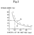
- Fig. 2 is a graph showing the relation between the diameter of the ink inlet hole and a Reynolds number;
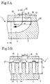
- Fig. 3A is an enlarged partial sectional view similar to Fig. 1A, showing the depth of a manifold;
- Fig. 3B is a partial cross section taken along the line III-III in Fig. 3A;
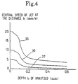
- Fig. 4 is a graph showing the relation between the depth of the manifold and the central speed of a jet;
- Fig. 5A is a view similar to Fig. 1A, showing the sectional area of the manifold and the total sectional area of ink chambers;
- Fig. 5B is a cross section taken along the line V-V in Fig. 5A;
- Fig. 6 is a graph showing the relation between the sectional area of a channel and a pressure loss;
- Fig. 7 is a graph showing the relation between the ratio of the sectional area of the manifold to the total sectional area of the ink chambers and a pressure loss;
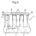
- Fig. 8 is a schematic partial sectional view similar to Fig. 1B, showing the depth of each ink chamber and the thickness of a cover plate;
- Fig. 9 is a graph showing the relation between the product of the depth of each ink chamber and the thickness of the cover plate and the flying speed of ink droplets;
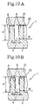
- Fig. 10A is a partial sectional view similar to Fig. 1B, showing when the bonded surface of the cover plate is smooth;
- Fig. 10B is a partial sectional view similar to Fig. 10A, showing when the bonded surface of the cover plate is rough;
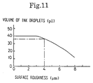
- Fig. 11 is a graph showing the relation between the surface roughness of the cover plate and the volume of ink droplets;
- Fig. 12A is a partial sectional view similar to Fig. 10A, showing the condition where an adhesive for bonding a piezoelectric ceramics plate and the cover plate is heated to be hardened when a coefficient of linear expansion of the piezoelectric ceramics plate is different from that of the cover plate;
- Fig. 12B is a partial sectional view similar to Fig. 12A, showing the condition where the adhesive heated to be hardened is returned to ordinary temperature;
- Fig. 13 is a table showing the result of an endurance test when various materials are used for the piezoelectric ceramics plate and the cover plate of the ink jet apparatus;
- Fig. 14 is an enlarged partial sectional view similar to Fig. 1A, showing the position of the manifold relative to each ink chamber;
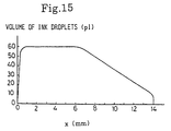
- Fig. 15 is a graph showing the relation between the position of the manifold and the volume of ink droplets;
- Fig. 16 is a partially cutaway perspective view of a shear mode type ink jet apparatus in the prior art;
- Fig. 17 is a schematic diagram of a control section of the ink jet apparatus shown in Fig. 16;
- Fig. 18 is a partial sectional view of the ink jet apparatus shown in Fig. 16; and
- Fig. 19 is a partial sectional view similar to Fig. 18, showing the operation of the ink jet apparatus.
- A preferred embodiment of the present invention is described referring to the drawings, in which the same members as those shown in Figs. 16 to 19 are denoted by the same reference numerals, and the explanation thereof will be omitted.
- Figs. 1A and 1B are enlarged views of an
ink inlet hole 16 and a manifold 18 in the preferred embodiment. Specifically, Fig. 1A is a cross section taken from the side of anink jet apparatus 1, and Fig. 1B is a cross section taken along the line I-I in Fig. 1A. - As shown in Fig. 1B, the
ink jet apparatus 1 includes apiezoelectric ceramics plate 2 and acover plate 10. Thepiezoelectric ceramics plate 2 has a plurality ofgrooves 3 and a plurality ofside walls 6 partitioning thegrooves 3. Thecover plate 10 has theink inlet hole 16 and the manifold 18. Thepiezoelectric ceramics plate 2 and thecover plate 10 are bonded together by an adhesive 20 to thereby define a plurality ofink chambers 4 as ink channels. - As shown by an
arrow 30 in Fig. 1A, ink is supplied from an ink tank (not shown) through an ink supply tube (not shown) into theink inlet hole 16 having a diameter d. Then, the ink is supplied from theink inlet hole 16 through the manifold 18 into eachink chamber 4. Since the manifold 18 has a sectional area larger than that of theink inlet hole 16 as shown, the ink flowing from theink inlet hole 16 into the manifold 18 is jetted therein. Accordingly, the ink undergoes a divergent flow loss due to rapid enlargement of a channel. A total flow loss occurring in the ink flowing from theink inlet hole 16 into the manifold 18 varies according to the state the ink is jetted in. When the ink is jetted in a state of laminar flow, the total flow loss is equal to the divergent flow loss. When the ink is jetted in a state of turbulent flow, the total flow loss is equal to the sum of the divergent flow loss and a turbulent flow loss. - To reduce the total flow loss and obtain a stable flow of the ink, excluding any small fluctuations, the jet state must be kept in the laminar flow state. To obtain the laminar flow state, it is known that a Reynolds number Re, which is an important parameter deciding the flow state of a fluid, must be reduced to about 30 or less (see for example, Dynamics of Viscous Fluid, Takefumi Ikui and Masahiro Inoue, p. 206, Rikogaku-sha). The Reynolds number Re is expressed as

ink inlet hole 16; d represents the diameter of theink inlet hole 16; and ν represents the coefficient of kinematic viscosity of the ink. If the consumption of the ink per unit time is fixed, the velocity u is in inverse proportion to the square of the diameter d of theink inlet hole 16. The Reynolds number Re is, therefore, in inverse proportion to the diameter d of theink inlet hole 16, as shown in Fig. 2. - In this preferred embodiment, the maximum consumption of the ink per unit time was set so that ink droplets in a volume of 40pl were simultaneously jetted from 25 nozzles at a frequency of 5kHz. A value of 10cps of pigment ink containing tripropylene glycol monomethylether (TPM) as a base at ordinary temperature was used as the coefficient of kinematic viscosity ν of the ink. Then, the diameter d of the
ink inlet hole 16 was varied to obtain the Reynolds number Re. The relation shown by asolid curve 32 in Fig. 2 was obtained as the result. - The Reynolds number Re is influenced not only by the diameter d of the
ink inlet hole 16 but also by the consumption of the ink per unit time and the coefficient of kinematic viscosity ν of the ink. The consumption of the ink per unit time cannot be reduced because a printing speed and clearness must be maintained. The coefficient of kinematic viscosity ν of the ink cannot be largely increased due to the need for stability of the jet of ink droplets. In particular, it is desired to prevent generation of unduly small ink droplets called satellites. Accordingly, there is a possibility that the relation between the Reynolds number Re and the diameter d of theink inlet hole 16 may shift upwards as shown by abroken line 34 in Fig. 2 according to a change in printing speed or ink viscosity. However, there is no possibility that the relation may shift downwards from thesolid line 32 calculated by using a minimum printing speed and a minimum ink viscosity. - Using the relation shown by the
solid line 32 in Fig. 2, the larger the diameter d of theink inlet hole 16, the less likely the jet state will become the turbulent flow state. As is apparent from Fig. 2, the diameter d of theink inlet hole 16 must be set to 0.2mm or more to reduce the Reynolds number Re to 30 or less. - As mentioned above, the jet state of the ink flowing from the
ink inlet hole 16 into the manifold 18 can be made into a laminar flow state by setting the diameter d of theink inlet hole 16 to 0.2 mm or more. Accordingly, the total flow loss occurring in the ink flowing from theink inlet hole 16 into the manifold 18 becomes the divergent flow loss, so that the total flow loss can be minimized, resulting in no turbulence of the ink flow in themanifold 18. Accordingly, the pressure of the ink in the manifold 18 becomes constant, and the pressure of the ink in eachink chamber 4 therefore becomes constant. As a result, the volume and the flying speed of ink droplets to be jetted become constant, thereby improving print quality. Further, since a desired amount of ink is supplied to eachink chamber 4, the volume of ink droplets to be jetted becomes a desired amount, thereby improving a print quality. - In this preferred embodiment, the size of the
ink inlet hole 16 having a circular shape is decided to reduce the Reynolds number Re to 30 or less. When theink inlet hole 16 is rectangular, elliptical, etc., the Reynolds number Re that will not cause a turbulent flow of ink may be obtained by carrying out a test to decide the size of theink inlet hole 16. - In the
ink jet apparatus 1 of this preferred embodiment, the ratio of pressure generated in eachink chamber 4 to driving voltage applied to eachelectrode 8 is large. Further, the ink flow into eachink chamber 4 is stable, and a resistance to the ink flow is small. Accordingly, a high pressure can be generated in eachink chamber 4 by applying a low driving voltage, and ink droplets can be jetted with a speed and a volume sufficient to form print images. According to theink jet apparatus 1 of this preferred embodiment, ink droplets can be stably jetted with a speed of about 3 to 8m/sec and a volume of about 30 to 90pl by applying a low driving voltage of about 20 to 50 volts. Thus, a driving circuit can be manufactured at a low cost with a small size. Theink jet apparatus 1 as a whole can therefore be manufactured at a low cost with a small size. - Now, the depth of the manifold 18 is described referring to Fig. 3a. As shown by an
arrow 30 in Fig. 3a, ink is supplied from an ink tank (not shown) through an ink supply tube (not shown) into theink inlet hole 16. Then, the ink is supplied from theink inlet hole 16 through the manifold 18 into eachink chamber 4. At this time, the ink in the manifold 18 flows, as shown byarrows 31 in Fig. 3B, into eachink chamber 4. Sinceink chambers ink inlet hole 16, the ink pressures in theink chambers ink inlet hole 16. - Fig. 4 shows a change in central speed of the ink jet when the ink flows from the
ink inlet hole 16 through the manifold 18 into theink chambers ink inlet hole 16. In Fig. 4, the axis of the abscissa represents the depth h of the manifold 18, and the axis of the ordinate represents the central speed of the jet. In this preferred embodiment, a test was carried out using three values of the diameter d of theink inlet hole 16 and setting a maximum ink consumption so that ink droplets in a volume of 40pl were simultaneously jetted from 20 nozzles at a frequency of 5kHz.Solid lines ink inlet hole 16 set to 0.7, 1.0, and 1.4mm, respectively. - As is apparent from Fig. 4, when the depth h of the manifold 18 is zero, the central speed u of the ink jet flowing from the
ink inlet hole 16 is maximum in each case. As well known, the central speed u of the ink jet is in inverse proportion to the square of the diameter d of theink inlet hole 16. The central speed u relatively rapidly decreases with an increase in depth h from zero. When the depth h becomes about 0.2mm or more, especially, 0.3mm or more, the central speed in becomes sufficiently small in each case. Even when the depth h is further increased, the central speed u hardly decreases in each case. Further, as far as the diameter d of theink inlet hole 16 is 0.2mm or more, a tendency similar to that shown in Fig. 4 is exhibited. - The flow velocity of the jet is proportional to the ink consumption per unit time, which varies according to a print pattern. Accordingly, unless the depth h of the manifold 18 is set to a value enough to diminish the influence of the ink jet flowing from the
ink inlet hole 16, the ink pressures in theink chambers ink inlet hole 16 would vary according to the print pattern, causing instability of jetting of the ink droplets. - Consequently, in the
ink jet apparatus 1 of this preferred embodiment, the depth h of the manifold 18 for distributing the ink flowing from theinlet hole 16 to eachink chamber 4 is set to 0.2mm or more, preferably 0.3mm or more. - Because the depth h of the manifold 18 is set to 0.2 mm or more, preferably 0.3mm or more, the ink flow into each ink chamber becomes stable and uniform. Accordingly, the pressure generated in each
ink chamber 4 upon application of a driving voltage to eachelectrode 8 becomes constant, and ink droplets can be jetted with a speed and a volume sufficient to form print images. According to theink jet apparatus 1 of this preferred embodiment, ink droplets can be stably and uniformly jetted with a speed of about 3 to 8m/sec and a volume of about 30 to 90pl by applying a driving voltage of about 20 to 50 volts. Further, since the ink flow into eachink chamber 4 is stable and uniform, it is not necessary to provide a function for correcting the ink flow in the driving circuit. Thus, the driving circuit can be simplified and made compact. Theink jet apparatus 1 can therefore be stabilized and manufactured at a low cost with a small size. - The relation between the sectional area of the manifold 18 and the total sectional area of the
ink chambers 4 is described referring to Fig. 5A. In this description, the sectional area of the manifold 18 means the area of a cross section perpendicular to the longitudinal direction of the manifold 18, and the total sectional area of theink chambers 4 means the total areas of the cross sections perpendicular to the longitudinal directions of all of theink chambers 4. - As shown by an
arrow 30 in Fig. 5A, ink is supplied from an ink tank (not shown) through an ink supply tube (not shown) into theink inlet hole 16. Then, the ink is supplied from theink inlet hole 16 through the manifold 18 into eachink chamber 4. At this time, the ink in the manifold 18 flows as shown byarrows 31 in Fig. 5B into eachink chamber 4. - The manifold 18 is a rectangular channel having a sectional area

ink chamber 4 is a rectangular channel having a sectional area
ink chamber 4, the flow resistance to the ink in a unit length of the channel is in substantially inverse proportion to the square of the sectional area of the channel, as shown in Fig. 6. This is true provided that the aspect ratio of the channel is kept substantially constant when the cross section of the channel changes in size. However, when the height and the width of the rectangular cross section are greatly different from each other, the relation shown in Fig. 6 is not obtained. Assuming that the height and the width of the rectangular cross section in both the manifold 18 and eachink chamber 4 are not greatly different from each other, the relation between the sectional area of the cross section and the flow resistance in both the manifold 18 and eachink chamber 4 shows a tendency similar to that shown in Fig. 6. - The ink flowing from the
ink inlet hole 16 undergoes a flow resistance in the manifold 18 and a flow resistance in eachink chamber 4 until the ink reaches each nozzle (not shown). In other words, the total flow resistance to the ink is the sum of the flow resistance in the manifold 18 and the flow resistance in all of theink chambers 4. As shown in Fig. 5B, a flow distance from theink inlet hole 16 to an ink chamber 4c is larger than a flow distance from theink inlet hole 16 to anink chamber 4a, for example. Therefore, the flow resistance to the ink that will flow into the ink chamber 4c becomes larger than the flow resistance to the ink that will flow into theink chamber 4a. Further, the ink that will flow into anotherink chamber 4 more distant from theink inlet hole 16 than the ink chamber 4c undergoes a larger flow resistance. - To make the ink flow into each
ink chamber 4 uniform, the manifold 18 is designed in such a manner that the flow resistance in the manifold 18 becomes uniform regardless of the position of eachink chamber 4. Alternatively, the manifold 18 is designed to have a sectional area such that the flow resistance in the manifold 18 is insignificant compared with the flow resistance in eachink chamber 4. The former method is impractical in general because the shape and the forming of the manifold 18 are complicated. Accordingly, the latter method will now be described. - Fig. 7 shows a change in total flow resistance to the ink in this preferred embodiment, in which the axis of abscissa represents a sectional area ratio S1/SA between the manifold 18 and all the
ink chambers 4. The sectional area SA of all of theink chambers 4 is equal to the product of the sectional area S2 of eachink chamber 4 and the number of all of theink chambers 4. In a test according to this preferred embodiment, the maximum ink consumption per unit time was set so that ink droplets in a volume of 40pl were simultaneously jetted from 50 nozzles at a frequency of 2.5kHz. A value of 10cps of pigment ink containing tripropylene glycol monomethylether (TPM) as a base at ordinary temperature was used as the coefficient of kinematic viscosity ν of the ink. The dimensions of eachink chamber 4 were the height H of 400µm, the width b of 80µm, and the length of 12mm. - In Fig. 7, a
solid line 38 is a curve showing the total flow resistance to the ink, and abroken line 39 is a line showing the flow resistance in theink chambers 4 only with no flow resistance in themanifold 18. As is apparent from Fig. 7, the total flow resistance rapidly increases on the left side of the sectional area ratio S1/SA with respect to a boundary value of about 1, that is, it rapidly increases with a decrease in sectional area ratio S1/SA from about 1. Further, when the sectional area ratio S1/SA increases from about 1, the total flow resistance rapidly approaches the flow resistance in theink chambers 4 only as shown by thebroken line 39. In other words, when the sectional area ratio S1/SA decreases from 1, the flow resistance in the manifold 18 rapidly increases; while, when the sectional area S1/SA increases from 1, the flow resistance in the manifold 18 rapidly decreases. - Accordingly, the sectional area ratio S1/SA needs to be set to 1 or more to reduce the flow resistance in the
manifold 18. Further, in an ink jet apparatus having a structure like that of this preferred embodiment, there is no possibility that the inks in theadjacent ink chambers 4 will be simultaneously jetted. Accordingly, the total sectional area of all of theink chambers 4 becomes half in reality. Even considering this fact, the sectional area ratio S1/SA needs to be set to 0.5 or more. - Thus, the increase in the sectional area ratio S1/SA is necessary for a reduction in flow resistance in the
manifold 18. However, when the sectional area ratio S1/SA becomes about 5 or more, the flow resistance in the manifold 18 is greatly reduced to 1% or less of the flow resistance in theink chambers 4, which is substantially insignificant. Accordingly, an increase in sectional area ratio S1/SA from about 5 merely causes enlargement of theink jet apparatus 1 and is hardly effective for the reduction in the total flow resistance. Thus, it is reasonable to set the sectional area ratio S1/SA to a value up to 5 from the viewpoints of a reduction in size and cost of theink jet apparatus 1. - In the test according to this preferred embodiment, the dimensions of each
ink chamber 4 were set to 400µm in height H, 80µm in width b, and 12mm in length. However, even when the dimensions of eachink chamber 4 are changed, the above preferable sectional area ratio S1/SA is unchanged. That is, as shown in Fig. 7, thecurve 38 showing a pressure loss is merely expanded or contracted in a vertical direction on the basis of the axis of abscissa as shown by abroken line - Consequently, in the
ink jet apparatus 1 of this preferred embodiment, the sectional area of the manifold 18 for distributing the ink having flowed from theink inlet hole 16 into eachink chamber 4 is set to about 0.5 to 5 times the total sectional area of all of theink chambers 4. - Because the sectional area of the manifold 18 is set to about 0.5 to 5 times the total sectional area of all the
ink chambers 4, the ink is substantially uniformly distributed through the manifold 18 into eachink chamber 4 with a low flow resistance. Accordingly, the ink can be smoothly introduced into eachink chamber 4, and a high pressure can be generated in eachink chamber 4 by applying a low driving voltage. Thus, ink droplets are jetted with a sufficient speed and a uniform volume to form print images. According to theink jet apparatus 1 of this preferred embodiment, ink droplets can be stably jetted with a speed of about 3 to 8m/sec and a volume of about 30 to 90pl by applying a low driving voltage of about 20 to 50 volts. Thus, a driving circuit can be manufactured at a low cost with a small size. Theink jet apparatus 1 as a whole can therefore be manufactured at a low cost with a small size. - Now, the depth of each
groove 3 forming eachink chamber 4 and the thickness of thecover plate 10 is described referring to Fig. 8 which is a sectional view of a part of theink jet apparatus 1 showing the shapes of thegrooves 3, theside walls 6, themetal electrodes 8, and thecover plate 10. Reference character b represents the width of eachgroove 3 formed on thepiezoelectric ceramics plate 2, and reference character H represents the depth of eachgroove 3. As eachmetal electrode 8 is formed on the upper half portion of eachside wall 6, the length from the upper end to the lower end of eachmetal electrode 8 becomes half of the depth H of eachgroove 3, that is, becomes H/2. Further, reference character k represents the thickness of thecover plate 10 made of the same material as that of thepiezoelectric ceramics plate 2. - The relation between the depth H of each
groove 3 forming eachink chamber 4 and the thickness k of thecover plate 10 was examined to obtain a flying speed of ink droplets necessary for stable printing. - In a test according to this preferred embodiment, three kinds of
piezoelectric ceramics plates 2 having different groove depths H of 0.2, 0.4, and 0.6mm were used. In eachpiezoelectric ceramics plate 2, the width of eachside wall 6 was set to 80µm, and the width b of eachgroove 3 was set to 80µm. Lead zirconate titanate (PZT) piezoelectric ceramics were used as the materials of thepiezoelectric ceramics plate 2 and thecover plate 10. An aluminum film having a thickness of about 1µm formed by vacuum deposition was used as eachmetal electrode 8, and an epoxy adhesive was used as the adhesive 20. Further, four kinds ofcover plates 10 having different thicknesses k of 0.25, 0.5, 1, and 2mm were used. Thus, twelve kinds ofink jet apparatus 1 were totally prepared by using the three kinds ofpiezoelectric ceramics plate 2 and the four kinds ofcover plates 10 in combination. Further, pigment ink containing tripropylene glycol monomethylether (TPM) as a base was used as the ink, and a driving voltage to be applied to eachmetal electrode 8 was set to 40 volts. The flying speed of ink droplets was calculated by emitting light from a light emitting diode in synchronism with a driving voltage pulse to form a still image of the droplets and shifting a timing of the light emission to the driving voltage pulse to obtain a travel of the still image of the ink droplets. - The flying speeds of ink droplets in the various kinds of
ink jet apparatus 1 prepared above were measured. The result of measurement is shown in Fig. 9, in which the axis of abscissa represents the product H x k of the depth H of eachgroove 3 and the thickness k of thecover plate 10 and the axis of ordinate represents the flying speed of ink droplets. In Fig. 9,solid lines ink jet apparatuses 1 having the depths H of 0.2, 0.4, and 0.6mm, respectively. - As is apparent from Fig. 9, the larger the depth H of each
groove 3, the larger the flying speed of droplets. In each of thesolid lines adjacent side walls 6 are deformed as shown by broken lines in Fig. 8 at the time of jetting of the ink, thecover plate 10 is minutely deformed as shown by broken lines in Fig. 8. The larger the rate of the deformation of thecover plate 10 to the volume of eachink chamber 4, the smaller the increase in pressure in eachink chamber 4, resulting in a reduction in flying speed of droplets. To reduce the rate of the deformation of thecover plate 10 to the volume of eachink chamber 4, it is necessary to either enlarge the depth H of eachgroove 3 or enlarge the thickness k of thecover plate 10. Accordingly, it is sufficient to enlarge the product H x k. As is apparent from Fig. 9, it is preferable to set the product H x k to 0.2 or more, so as not to rapidly decrease the flying speed of ink droplets. - While the width of each
side wall 6 was set to 80µm in the above test according to this preferred embodiment, a tendency similar to that shown in Fig. 9 is exhibited even when the width of eachside wall 6 varies from the above value. - Further, while the width b of each
groove 3 was set to 80µm in the above test, a tendency similar to that shown in Fig. 9 is exhibited when the width b of eachgroove 3 is about 80µm. - Consequently, in the
ink jet apparatus 1 according to this preferred embodiment, the product of the depth of eachgroove 3 and the thickness of thecover plate 10 is set to 0.2 (mm x mm) or more. - Because the product of the depth of each
groove 3 and the thickness of thecover plate 10 is set to 0.2 (mm x mm) or more, the deformation of thecover plate 10 due to the deformation of theside walls 6 can be prevented as much as possible. Accordingly, the ratio of the pressure generated in eachink chamber 4 to the driving voltage to be applied to eachmetal electrode 8 can be increased. Accordingly, a high pressure can be generated in eachink chamber 4 by applying a low driving voltage, and ink droplets can be jetted with a speed and a volume enough to form print images. According to theink jet apparatus 1 of this preferred embodiment, ink droplets can be jetted with a speed of about 3 to 8m/sec and a volume of about 30 to 90pl by applying a low driving voltage of about 20 to 50 volts. Thus, a driving circuit can be manufactured at a low cost with a small size. Theink jet apparatus 1 as a whole can therefore be manufactured at a low cost with a small size. - The influence of the surface roughness of the
cover plate 10 to ink jet characteristics is described referring to Fig. 10A. As shown, eachside wall 6 is integral at a lower end thereof with thepiezoelectric ceramics plate 2, and an upper end of eachside wall 6 is bonded to thecover plate 10 by the adhesive 20. When the surface of thecover plate 10 is smooth, a very thin film of the adhesive 20 is formed between eachside wall 6 and thecover plate 10, and a bonded portion formed by the adhesive 20 has a high rigidity. On the other hand, when the surface of thecover plate 10 is rough, a large amount of the adhesive 20 is interposed between eachside wall 6 and thecover plate 10 as shown in Fig. 10B to cause a low rigidity of the bonded portion. As a result, the pressure generated in eachink chamber 4 upon jetting of ink droplets cannot be sufficiently increased, so that a desired volume of the ink droplets cannot be obtained. - The volume of ink droplets jetted was measured by using the
cover plates 10 having different surface roughnesses. - In the
ink jet apparatus 1 used in this test, the width W of eachside wall 6 was set to 80µm, the depth H of eachgroove 3 equal to the height of eachside wall 6 was set to 400µm, and the width b of eachgroove 3 was set to 80µm. Lead zirconate titanate (PZT) piezoelectric ceramics were used as the materials of thepiezoelectric ceramics plate 2 and eachcover plate 10. An aluminum film having a thickness of about 1µm formed by vapor deposition was used as eachmetal electrode 8. Further, an epoxy adhesive was used as the adhesive 20. The thickness k of eachcover plate 10 was set to 1mm, and the surface roughness of the surface to be bonded to eachside wall 6 was changed from 1 to 8µm. Further, to eliminate any influences other than the influence of the surface roughness, the adhesive 20 was applied uniformly and thinly in all thecover plates 10 having the different surface roughnesses. The volume of ink droplets was calculated by measuring the weight of a predetermined number of the ink droplets with use of a high-precision analysis balance and by using the weight thus measured and the density of the ink. - As is apparent from Fig. 11, when the surface roughness of the
cover plate 10 is 3µm or less, the volume of the ink droplets is maximum and substantially constant. In comparison with this, when the surface roughness increases to about 4µm, the volume of the ink droplets decreases about 10%. Further, when the surface roughness increases to about 5µm or more, the volume of the ink droplets decreases 20% or more, causing a remarkable reduction in formation efficiency of the ink droplets. - Another jet test using the
ink jet apparatus 1 having any dimensions other than the above dimensions was carried out. As the result of this test, an absolute amount of the volume of ink droplets changes, but a manner of change due to the surface roughness of thecover plate 10 is similar to that shown in Fig. 11. - Further, even when any adhesive (e.g., phenol adhesive) other than the epoxy adhesive is used, a tendency similar to that shown in Fig. 11 is exhibited.
- Consequently, in the
ink jet apparatus 1 according to this preferred embodiment, the surface roughness of thecover plate 10 is set to 5µm or less, preferably 3µm or less. - Because the surface roughness of the
cover plate 10 is set to 5µm or less, preferably 3µm or less, the ratio of the pressure generated in eachink chamber 4 to the driving voltage applied to eachmetal electrode 8 is large. Accordingly, a high pressure can be generated in eachink chamber 4 by applying a low driving voltage, and ink droplets can be jetted with a speed and a volume enough to form print images. According to theink jet apparatus 1 of this preferred embodiment, ink droplets can be jetted with a speed of about 3 to 8m/sec and a volume of about 30 to 90pl, which depends on the length of eachink chamber 4, by applying a low driving voltage of about 20 to 50 volts. Thus, a driving circuit can be manufactured at a low cost with a small size. Theink jet apparatus 1 as a whole can therefore be manufactured at a low cost with a small size. - The influence of a difference in material between the
piezoelectric ceramics plate 2 and thecover plate 10 to the endurance of theink jet apparatus 1 is described referring to Fig. 12A. As shown, thepiezoelectric ceramics plate 2 of theink jet apparatus 1 is formed with a plurality ofgrooves 3 each forming anink chamber 4 and with a plurality ofside walls 6 partitioning thegrooves 3. The width b of eachgroove 3 is set to 80µm, and the depth H of eachgroove 3 is set to 400µm. The width W of eachside wall 6 is set to 80µm. The upper end surface of eachside wall 6 is bonded to thecover plate 10 by an adhesive 20. A thermosetting adhesive such as an epoxy adhesive is used as the adhesive 20. The adhesive 20 is hardened by heating up to about 160°C. The thickness of thecover plate 10 is set to 1mm. - In the
ink jet apparatus 1 as mentioned above, the material of thepiezoelectric ceramics plate 2 is not necessarily the same as the material of thecover plate 10. Accordingly, when the material of thepiezoelectric ceramics plate 2 has a coefficient of linear expansion different from that of the material of thecover plate 10, the deformation of both members becomes nonuniform when the temperature of the adhesive 20 after being hardened by heating is returned to ordinary temperature. As a result, even when eachside wall 6 is bonded to thecover plate 10 at about 160°C in such a manner that theadjacent side walls 6 are parallel to each other as shown in Fig. 12A, theside walls 6 are deformed after reaching ordinary temperatures as shown in Fig. 12B, a residual stress is generated in eachside wall 6 and the adhesive 20 reducing the strength of a bonded portion, in particular. - In general, the magnitude of the residual stress is dependent upon not only a difference in coefficient of linear expansion but also an elastic modulus (Young's modulus) of material. In the
ink jet apparatus 1 of this preferred embodiment, however, thecover plate 10 is sufficiently thick as compared with eachside wall 6. Thus, the influence caused by a change in Young's modulus due to a difference in material of thecover plate 10 is substantially insignificant. - Then, the influence of the above phenomenon to the life of the
ink jet apparatus 1 was examined. By using three kinds of lead zirconate titanate (PZT) piezoelectric ceramics having three coefficients of linear expansion of 1, 2, and 4ppm/°C, three kinds ofpiezoelectric ceramics plates 2 having different coefficients of linear expansion were prepared. Further, three kinds ofcover plates 10 having the same materials as those of the abovepiezoelectric ceramics plates 2 were prepared. Additionally, three kinds ofcover plates 10 made of magnesia (MgO), zirconia (ZrO2), and alumina (Al2O3) were prepared. Thus, six kinds ofcover plates 10 having different coefficients of linear expansion were totally prepared. - By using the various kinds of
piezoelectric ceramics plates 2 and the various kinds ofcover plates 10 mentioned above, variousink jet apparatuses 1 were prepared. Then, driving pulses at a voltage level of 40 volts continued to be applied at a frequency of 8kHz to eachink jet apparatus 1. At this time, the number of times of the applied driving pulses was measured until the jet function of eachink jet apparatus 1 was reduced to a degree such that ink droplets could not be formed. - The result of measurement is shown in Fig. 13. As is apparent from Fig. 13, when the difference in coefficient of linear expansion between the
piezoelectric ceramics plate 2 and thecover plate 10 is 6.0ppm/°C or less, the life of theink jet apparatus 1 is 30 x 108 times. In contrast, when the difference in coefficient of linear expansion becomes 8.5ppm/°C, the life decreases to 20 x 108 times. Further, when the difference in coefficients of linear expansion becomes larger, the life decreases more remarkably. - While an epoxy adhesive is used as the adhesive 20 in this preferred embodiment, any other thermosetting adhesives such as a phenol adhesive may be used. Also in these cases, a tendency similar to that shown in Fig. 13 is exhibited.
- Consequently, in the
ink jet apparatus 1 of this preferred embodiment, the difference in coefficients of linear expansion between thepiezoelectric ceramics plate 2 and thecover plate 10 is set to 8.5ppm/°C or less, preferably 6.0ppm/°C or less. - Because the difference in coefficients of linear expansion between the
piezoelectric ceramics plate 2 and thecover plate 10 is set to 8.5ppm/°C or less, preferably 6.0ppm/°C or less, the jet life of theink jet apparatus 1 becomes at least about 20 x 108 times, preferably 30 x 108 times which is sufficient in practical use. Accordingly, theink jet apparatus 1 can be sufficiently applied to not only printing of character images but also printing of graphics images requiring a great frequency of jets of ink. Accordingly, the number of replacements of theink jet apparatus 1 in a printer can be reduced, and the reliability of the printer can be improved. - The relative positional relationship between each
ink chamber 4 and the manifold 18 is described referring to Fig. 14 which shows a cross section of theink jet apparatus 1 as viewed from one side thereof. As shown by anarrow 30 in Fig. 14, ink is supplied from an ink tank (not shown) through an ink supply tube (not shown) into theink inlet hole 16. Then, the ink is supplied from theink inlet hole 16 through the manifold 18 into eachink chamber 4. In a test using theink jet apparatus 1, lead zirconate titanate (PZT) piezoelectric ceramics were used as the materials of thepiezoelectric ceramics plate 2 and thecover plate 10. To examine a change in volume of ink droplets due to a change in relative positional relationship between the manifold 18 and eachink chamber 4, variousink jet apparatuses 1 were prepared having different distances x from the front side surface of the manifold 18 to the rear end surface of eachink chamber 4. However, in eachink jet apparatus 1, the full length L of eachink chamber 4 was set to 17mm. Further, in eachink jet apparatus 1, the depth h of the manifold 18 was set to 0.5mm, and the width w of the manifold 18 was set to 5mm. The volume of ink droplets was calculated by measuring the weight of a predetermined number of the ink droplets jetted with use of a high-precision analysis balance and by using the weight thus measured and the density of the ink. - Using the above various
ink jet apparatuses 1 having different relative positional relationship between the manifold 18 and eachink chamber 4, the volume of ink droplets jetted from eachink jet apparatus 1 was measured. The result of measurement is shown in Fig. 15, in which the axis of abscissa represents the distance x between the front side surface of the manifold 18 and the rear end surface of eachink chamber 4, and the axis of ordinate represents the volume of ink droplets. As is apparent from Fig. 15, when the distance x ranges between 1mm and 6mm, the volume of ink droplets reaches a maximum value of 60pl, which is kept substantially constant. - When the distance x becomes 1mm or less, the volume of ink droplets rapidly decreases. Further, when the distance x decreases to about 0.2mm, the ink cannot be jetted. That is, x = 1 means that the distance of overlap between the manifold 18 and each
ink chamber 4 is equal to 1mm, and a decrease in the distance x down from 1mm causes the ink flow into eachink chamber 4 to become rapidly hard. - On the other hand, when the distance x becomes 6mm or more, the volume of ink droplets does not decrease as rapidly. This is due to the fact that an increase in the distance x results in an approach of the manifold 18 to a
nozzle plate 14, that is, the distance y between the front side surface of the manifold 18 and the inner surface of thenozzle plate 14. When the pressure in eachink chamber 4 is increased to jet the ink droplets from anozzle 12 formed through thenozzle plate 14, the ink in eachink chamber 4 is forced from thenozzle 12. Simultaneously, it reversely flows from the manifold 18 into theink inlet hole 16. As a result, the pressure near the manifold 18 is rapidly reduced to generate a negative pressure wave. When this negative pressure wave reaches thenozzle 12, the ink jet from thenozzle 12 is stopped. The shorter the distance y, the shorter the time of reach of the negative pressure wave to thenozzle 12. Accordingly, when the distance y is reduced, the ink jet from thenozzle 12 is quickly stopped to result in a reduction in the volume of ink droplets. - As is apparent from Fig. 15, when the distance x becomes about 11mm (

ink chamber 4 must be defined so that the distance x is set to 0.2mm or more and the distance y is set to 3mm or more, preferably 6mm or more. - While the depth h and the width w of the manifold 18 were set to 0.5mm and 5mm, respectively, in the above test, a tendency similar to that shown in Fig. 15 is exhibited even when the dimensions of the manifold 18 vary from the above values.
- Further, while the full length L of each
ink chamber 4 was set to 17mm in the above test, a tendency similar to that shown in Fig. 15 is exhibited even when the full length L varies from 17mm. - Consequently, in the
ink jet apparatus 1 according to this preferred embodiment, the position of the manifold 18 to be formed in thecover plate 10 relative to eachink chamber 4 is such that the distance between the front side surface of the manifold 18 and the rear end surface of eachink chamber 4 is set to 0.2mm or more. Also, the distance between the front side surface of the manifold 18 and the inner surface of thenozzle plate 14 is set to 3mm or more, preferably 6mm or more. - Because the distance between the front side surface of the manifold 18 and the rear end surface of each
ink chamber 4 is set to 0.2mm or more and the distance between the front side surface of the manifold 18 and the inner surface of thenozzle plate 14 is set to 3mm or more, preferably 6mm or more, the ink droplets can be efficiently jetted and the ink can be smoothly supplied to eachink chamber 4. Accordingly, the ink droplets can be jetted with a speed and a volume sufficient to form print images. According to theink jet apparatus 1 of this preferred embodiment, ink droplets can be jetted with a speed of about 3 to 8m/sec and a volume of about 30 to 90pl by applying a low driving voltage of about 20 to 50 volts. Thus, a driving circuit can be manufactured at a low cost with a small size. Theink jet apparatus 1 as a whole can therefore be manufactured at a low cost with a small size. - It is to be noted that the present invention is not limited to the preferred embodiment described above, but various modifications may be made without departing from the scope of the present invention.
- For example, while the
ink jet apparatus 1 of the preferred embodiment is of a shear mode type, such that the ink in eachink chamber 4 is jetted by the shear mode deformation of eachside wall 6 made of piezoelectric ceramics, the ink jet apparatus according to the present invention may be another type, such as a Kaiser type or a thermal jet type as mentioned previously.
Claims (16)
- An ink jet printing apparatus comprising:a plate (2) with a plurality of longitudinally extending upstanding walls (6) defining parallel ink chambers (4), each of said ink chambers (4) having a front end and a rear end;a nozzle assembly (14) coupled to said plate (2) at said front end of said ink chambers (4) and having nozzles (12) formed therein, said nozzles (12) being aligned with said ink chambers (4); anda cover (10) coupled to said plate (2) and closing said ink chambers (4), said cover (10) including an ink manifold (18) having a front side and a rear side and being in communication with said ink chambers (4) and including an ink inlet (16) in said manifold (18) for introducing ink into said manifold (18);wherein a distance between said front side of said manifold (18) and said rear end of said ink chambers (4) is in the range of 0.2mm to 6mm and a distance between said front side of said manifold (18) and said front end of said ink chambers (4) at said nozzle (12) is at least 3mm.
- An ink jet printing apparatus according to claim 1 wherein said distance between said front side of said manifold (18) and said front end of said ink chambers (4) at said nozzle (12) is at least 6mm.
- An ink jet printing apparatus comprising:a plate (2) with a plurality of longitudinally extending upstanding walls (6) defining parallel ink chambers (4), each of said ink chambers (4) having a front end and a rear end;a nozzle assembly (14) coupled to said plate (2) at said front end of said ink chambers (4) and having nozzles (12) formed therein, said nozzles (12) being aligned with said ink chambers (4); anda cover (10) coupled to said plate (2) and closing said ink chambers (4), said cover (10) including an ink manifold (18) having a front side and a rear side and being in communication with said ink chambers (4) and including an ink inlet (16) in said manifold (18) for introducing ink into said manifold (18);wherein each of said ink chambers (4) has a depth and said cover (10) has a thickness, and wherein said depth times said thickness is 0.2mm2 or more, which suppresses deformation of said cover (10).
- An ink jet printing apparatus comprising:a plate (2) with a plurality of longitudinally extending upstanding walls (6) defining parallel ink chambers (4), each of said ink chambers having a front end and a rear end;a nozzle assembly (14) coupled to said plate (2) at said front end of said ink chambers (4) and having nozzles (12) formed therein, said nozzles (12) being aligned with said ink chambers (4); anda cover (10) coupled to said plate (12) and closing said ink chambers (4), said cover (10) including an ink manifold (18) having a front side and a rear side and being in communication with said ink chambers (4) and including an ink inlet (16) in said manifold (18) for introducing ink into said manifold (18);wherein said cover (10) has a surface that faces said plate (2) and said surface has a roughness of 5µm or less.
- An ink jet printing apparatus according to claim 4 wherein said surface has a roughness of 3µm or less.
- An ink jet printing apparatus comprising:a plate (2) with a plurality of longitudinally extending upstanding walls (6) defining parallel ink chambers (4), each of said ink chambers having a front end and a rear end;a nozzle assembly (14) coupled to said plate (2) at said front end of said ink chambers (4) and having nozzles (12) formed therein, said nozzles (12) being aligned with said ink chambers (4); anda cover (10) coupled to said plate (2) and closing said ink chambers (4), said cover (10) including an ink manifold (18) having a front side and a rear side and being in communication with said ink chambers (4) and including an ink inlet in said manifold (18) for introducing ink into said manifold (18);wherein said ink inlet (12) is sized to create a laminar flow of ink into said manifold.
- An ink jet printing apparatus comprising:a plate (2) with a plurality of longitudinally extending upstanding walls (6) defining parallel ink chambers (4), each of said ink chambers (4) having a front end and a rear end;a nozzle assembly (14) coupled to said plate (2) at said front end of said ink chambers (4) and having nozzles (12) formed therein, said nozzles (12) being aligned with said ink chambers (4); anda cover (10) coupled to said plate (2) and closing said ink chambers (4), said cover (10) including an ink manifold (18) having a front side and a rear side and being in communication with said ink chambers (4) and including an ink inlet (16) in said manifold (18) for introducing ink into said manifold (18);wherein each of said ink chambers (4) has a cross-sectional area and said manifold (18) has a cross-sectional area, and wherein the cross-sectional area of said manifold (18) is at least 0.5 times the cross-sectional area of all of said ink chambers (4) combined.
- An ink jet printing apparatus according to claim 7, wherein the cross-sectional area of said manifold (18) is at most 5 times the cross-sectional area of all of said ink chambers (4) combined.
- An ink jet printing apparatus comprising:a plate (2) with a plurality of longitudinally extending upstanding walls (6) defining parallel ink chambers (4), each of said ink chambers (4) having a front end and a rear end;a nozzle assembly (14) coupled to said plate (2) at said front end of said ink chambers (4) and having nozzles (12) formed therein, said nozzles (12) being aligned with said ink chambers (4); anda cover (10) coupled to said plate (2) and closing said ink chambers (4), said cover (10) including an ink manifold (18) having a front side and a rear side and being in communication with said ink chambers (4) and including an ink inlet (16) in said manifold (18) for introducing ink into said manifold (18);wherein said manifold (18) has a depth that allows ink to flow into said ink chambers (4) without a change in pressure.
- An ink jet printing apparatus according to any preceding claim except claim 7 or 8 wherein each of said ink chambers (4) has a cross-sectional area and said manifold (18) has a cross-sectional area, and wherein the cross-sectional area of said manifold (18) is in a range of 0.5 to 5 times the cross-sectional area of all of said ink chambers (4) combined.
- An ink jet printing apparatus according to any preceding claim except claim 3 or claim 10 when dependent on claim 3 wherein each of said ink chambers (4) has a depth and said cover (10) has a thickness, and wherein said depth times said thickness is 0.2mm2 or more, which suppresses deformation of said cover.
- An ink jet printing apparatus according to any preceding claim except claim 4 or 5 or claim 10 or 11 when dependent on claim 4 or 5 wherein said cover has a surface that faces said plate (2) and said surface has a roughness of 5µm or less, preferably 3µm or less.
- An ink jet printing apparatus according to any preceding claim wherein said ink inlet (16) has a diameter of at least 0.2mm.
- An ink jet printing apparatus according to any preceding claim wherein said manifold (18) has a depth of at least 0.2mm.
- An ink jet printing apparatus according to claim 14 wherein said manifold (18) has a depth of at least 0.3mm.
- An ink jet printing apparatus according to any preceding claim wherein said plate (2) and said cover (10) are bonded together with thermosetting adhesive.
Priority Applications (2)
| Application Number | Priority Date | Filing Date | Title |
|---|---|---|---|
| EP97114689A EP0810094B1 (en) | 1993-02-10 | 1994-02-10 | Ink jet apparatus |
| EP97114688A EP0810093B1 (en) | 1993-02-10 | 1994-02-10 | Ink jet apparatus |
Applications Claiming Priority (4)
| Application Number | Priority Date | Filing Date | Title |
|---|---|---|---|
| JP2257193 | 1993-02-10 | ||
| JP22571/93 | 1993-02-10 | ||
| JP5022571A JPH06234216A (en) | 1993-02-10 | 1993-02-10 | Ink injection device |
| EP94300968A EP0611154B2 (en) | 1993-02-10 | 1994-02-10 | Ink jet apparatus |
Related Parent Applications (2)
| Application Number | Title | Priority Date | Filing Date |
|---|---|---|---|
| EP94300968.8 Division | 1994-02-10 | ||
| EP94300968A Division EP0611154B2 (en) | 1993-02-10 | 1994-02-10 | Ink jet apparatus |
Related Child Applications (2)
| Application Number | Title | Priority Date | Filing Date |
|---|---|---|---|
| EP97114689A Division EP0810094B1 (en) | 1993-02-10 | 1994-02-10 | Ink jet apparatus |
| EP97114688A Division EP0810093B1 (en) | 1993-02-10 | 1994-02-10 | Ink jet apparatus |
Publications (3)
| Publication Number | Publication Date |
|---|---|
| EP0774355A2 true EP0774355A2 (en) | 1997-05-21 |
| EP0774355A3 EP0774355A3 (en) | 1997-11-19 |
| EP0774355B1 EP0774355B1 (en) | 1999-11-17 |
Family
ID=26136921
Family Applications (1)
| Application Number | Title | Priority Date | Filing Date |
|---|---|---|---|
| EP97101749A Expired - Lifetime EP0774355B1 (en) | 1993-02-10 | 1994-02-10 | Ink jet apparatus |
Country Status (1)
| Country | Link |
|---|---|
| EP (1) | EP0774355B1 (en) |
Citations (3)
| Publication number | Priority date | Publication date | Assignee | Title |
|---|---|---|---|---|
| JPS5312138A (en) | 1976-07-19 | 1978-02-03 | Ohbayashigumi Ltd | Method of improving earthquake resistance performance of reinforced concrete construction frame |
| US4887100A (en) | 1987-01-10 | 1989-12-12 | Am International, Inc. | Droplet deposition apparatus |
| JPH06159914A (en) | 1992-11-24 | 1994-06-07 | Sanyo Electric Co Ltd | Medicine cold insulating storage |
Family Cites Families (3)
| Publication number | Priority date | Publication date | Assignee | Title |
|---|---|---|---|---|
| GB8824014D0 (en) * | 1988-10-13 | 1988-11-23 | Am Int | High density multi-channel array electrically pulsed droplet deposition apparatus |
| JPH04363250A (en) * | 1991-03-19 | 1992-12-16 | Tokyo Electric Co Ltd | Ink jet printer head and method for its production |
| JP2744535B2 (en) * | 1991-07-08 | 1998-04-28 | 株式会社テック | Method of manufacturing ink jet printer head |
-
1994
- 1994-02-10 EP EP97101749A patent/EP0774355B1/en not_active Expired - Lifetime
Patent Citations (3)
| Publication number | Priority date | Publication date | Assignee | Title |
|---|---|---|---|---|
| JPS5312138A (en) | 1976-07-19 | 1978-02-03 | Ohbayashigumi Ltd | Method of improving earthquake resistance performance of reinforced concrete construction frame |
| US4887100A (en) | 1987-01-10 | 1989-12-12 | Am International, Inc. | Droplet deposition apparatus |
| JPH06159914A (en) | 1992-11-24 | 1994-06-07 | Sanyo Electric Co Ltd | Medicine cold insulating storage |
Also Published As
| Publication number | Publication date |
|---|---|
| EP0774355B1 (en) | 1999-11-17 |
| EP0774355A3 (en) | 1997-11-19 |
Similar Documents
| Publication | Publication Date | Title |
|---|---|---|
| EP0611154B1 (en) | Ink jet apparatus | |
| US4367480A (en) | Head device for ink jet printer | |
| US20060050107A1 (en) | Liquid-discharge recording head | |
| US20030098901A1 (en) | Ink jet recording head and ink jet recording apparatus | |
| EP0609080B1 (en) | Ink jet apparatus | |
| US20040041881A1 (en) | Liquid drop discharging head and liquid drop discharging device | |
| US5471231A (en) | Ink jet head | |
| JP7106917B2 (en) | Liquid ejecting head and liquid ejecting device | |
| JP2009226943A (en) | Liquid-jetting head and liquid-jetting device | |
| US20020171711A1 (en) | Ink jet printing head and ink jet printing device enabling stable high-frequency ink drop ejection and high-speed printing | |
| US6036303A (en) | Inkjet recording head for reducing crosstalk | |
| EP0461939A2 (en) | Ink jet recording apparatus using heat generating element | |
| EP0774355B1 (en) | Ink jet apparatus | |
| US5898448A (en) | Ink ejecting device having ink chambers of differing shapes | |
| EP1024004B1 (en) | Ink jet recording head and image recording apparatus incorporating the same | |
| JPH06234210A (en) | Ink injection device | |
| JPH06234214A (en) | Ink injection device | |
| JPH06234215A (en) | Ink injection device | |
| JPH06234213A (en) | Ink injection device | |
| JPH06234212A (en) | Ink injection device | |
| JPH06234211A (en) | Ink injection device | |
| JP2016128271A (en) | Liquid spray head | |
| JPH06226973A (en) | Ink jet apparatus | |
| JPH0717039A (en) | Driving method of ink jet device | |
| JPH0557889A (en) | Ink jet recording head |
Legal Events
| Date | Code | Title | Description |
|---|---|---|---|
| PUAI | Public reference made under article 153(3) epc to a published international application that has entered the european phase |
Free format text: ORIGINAL CODE: 0009012 |
|
| 17P | Request for examination filed |
Effective date: 19970205 |
|
| AC | Divisional application: reference to earlier application |
Ref document number: 611154 Country of ref document: EP |
|
| AK | Designated contracting states |
Kind code of ref document: A2 Designated state(s): DE GB SE |
|
| PUAL | Search report despatched |
Free format text: ORIGINAL CODE: 0009013 |
|
| AK | Designated contracting states |
Kind code of ref document: A3 Designated state(s): DE GB SE |
|
| 17Q | First examination report despatched |
Effective date: 19980608 |
|
| GRAG | Despatch of communication of intention to grant |
Free format text: ORIGINAL CODE: EPIDOS AGRA |
|
| GRAG | Despatch of communication of intention to grant |
Free format text: ORIGINAL CODE: EPIDOS AGRA |
|
| GRAH | Despatch of communication of intention to grant a patent |
Free format text: ORIGINAL CODE: EPIDOS IGRA |
|
| GRAH | Despatch of communication of intention to grant a patent |
Free format text: ORIGINAL CODE: EPIDOS IGRA |
|
| GRAA | (expected) grant |
Free format text: ORIGINAL CODE: 0009210 |
|
| AC | Divisional application: reference to earlier application |
Ref document number: 611154 Country of ref document: EP |
|
| AK | Designated contracting states |
Kind code of ref document: B1 Designated state(s): DE GB SE |
|
| XX | Miscellaneous (additional remarks) |
Free format text: TEILANMELDUNG 97114688.1 EINGEREICHT AM 25/08/97. |
|
| REF | Corresponds to: |
Ref document number: 69421725 Country of ref document: DE Date of ref document: 19991223 |
|
| PLBE | No opposition filed within time limit |
Free format text: ORIGINAL CODE: 0009261 |
|
| STAA | Information on the status of an ep patent application or granted ep patent |
Free format text: STATUS: NO OPPOSITION FILED WITHIN TIME LIMIT |
|
| 26N | No opposition filed | ||
| REG | Reference to a national code |
Ref country code: GB Ref legal event code: IF02 |
|
| PGFP | Annual fee paid to national office [announced via postgrant information from national office to epo] |
Ref country code: SE Payment date: 20130207 Year of fee payment: 20 Ref country code: DE Payment date: 20130228 Year of fee payment: 20 Ref country code: GB Payment date: 20130125 Year of fee payment: 20 |
|
| REG | Reference to a national code |
Ref country code: DE Ref legal event code: R071 Ref document number: 69421725 Country of ref document: DE |
|
| REG | Reference to a national code |
Ref country code: GB Ref legal event code: PE20 Expiry date: 20140209 |
|
| REG | Reference to a national code |
Ref country code: SE Ref legal event code: EUG |
|
| PG25 | Lapsed in a contracting state [announced via postgrant information from national office to epo] |
Ref country code: GB Free format text: LAPSE BECAUSE OF EXPIRATION OF PROTECTION Effective date: 20140209 Ref country code: DE Free format text: LAPSE BECAUSE OF EXPIRATION OF PROTECTION Effective date: 20140211 |