EP0774317A1 - Pulsed arc welding method and apparatus - Google Patents
Pulsed arc welding method and apparatus Download PDFInfo
- Publication number
- EP0774317A1 EP0774317A1 EP96118265A EP96118265A EP0774317A1 EP 0774317 A1 EP0774317 A1 EP 0774317A1 EP 96118265 A EP96118265 A EP 96118265A EP 96118265 A EP96118265 A EP 96118265A EP 0774317 A1 EP0774317 A1 EP 0774317A1
- Authority
- EP
- European Patent Office
- Prior art keywords
- time
- value
- mean value
- short circuit
- base
- Prior art date
- Legal status (The legal status is an assumption and is not a legal conclusion. Google has not performed a legal analysis and makes no representation as to the accuracy of the status listed.)
- Granted
Links
- 238000003466 welding Methods 0.000 title claims abstract description 107
- 238000000034 method Methods 0.000 title claims description 16
- 239000010953 base metal Substances 0.000 claims abstract description 10
- 238000002844 melting Methods 0.000 claims abstract description 5
- 230000008018 melting Effects 0.000 claims abstract description 5
- 230000003247 decreasing effect Effects 0.000 claims description 27
- 238000010586 diagram Methods 0.000 description 8
- 230000001276 controlling effect Effects 0.000 description 7
- 230000007423 decrease Effects 0.000 description 7
- 230000001105 regulatory effect Effects 0.000 description 4
- 238000004804 winding Methods 0.000 description 4
- 238000001514 detection method Methods 0.000 description 2
- 239000000463 material Substances 0.000 description 2
- 230000003466 anti-cipated effect Effects 0.000 description 1
- 230000005669 field effect Effects 0.000 description 1
- 238000009499 grossing Methods 0.000 description 1
- 230000010354 integration Effects 0.000 description 1
- 230000001788 irregular Effects 0.000 description 1
Images


Classifications
-
- B—PERFORMING OPERATIONS; TRANSPORTING
- B23—MACHINE TOOLS; METAL-WORKING NOT OTHERWISE PROVIDED FOR
- B23K—SOLDERING OR UNSOLDERING; WELDING; CLADDING OR PLATING BY SOLDERING OR WELDING; CUTTING BY APPLYING HEAT LOCALLY, e.g. FLAME CUTTING; WORKING BY LASER BEAM
- B23K9/00—Arc welding or cutting
- B23K9/09—Arrangements or circuits for arc welding with pulsed current or voltage
- B23K9/091—Arrangements or circuits for arc welding with pulsed current or voltage characterised by the circuits
- B23K9/092—Arrangements or circuits for arc welding with pulsed current or voltage characterised by the circuits characterised by the shape of the pulses produced
-
- B—PERFORMING OPERATIONS; TRANSPORTING
- B23—MACHINE TOOLS; METAL-WORKING NOT OTHERWISE PROVIDED FOR
- B23K—SOLDERING OR UNSOLDERING; WELDING; CLADDING OR PLATING BY SOLDERING OR WELDING; CUTTING BY APPLYING HEAT LOCALLY, e.g. FLAME CUTTING; WORKING BY LASER BEAM
- B23K9/00—Arc welding or cutting
- B23K9/06—Arrangements or circuits for starting the arc, e.g. by generating ignition voltage, or for stabilising the arc
- B23K9/073—Stabilising the arc
- B23K9/0735—Stabilising of the arc length
-
- B—PERFORMING OPERATIONS; TRANSPORTING
- B23—MACHINE TOOLS; METAL-WORKING NOT OTHERWISE PROVIDED FOR
- B23K—SOLDERING OR UNSOLDERING; WELDING; CLADDING OR PLATING BY SOLDERING OR WELDING; CUTTING BY APPLYING HEAT LOCALLY, e.g. FLAME CUTTING; WORKING BY LASER BEAM
- B23K9/00—Arc welding or cutting
- B23K9/095—Monitoring or automatic control of welding parameters
- B23K9/0956—Monitoring or automatic control of welding parameters using sensing means, e.g. optical
Definitions
- the present invention relates to a pulsed arc welding method and apparatus in which a droplet of a consumable electrode is transferred to a base metal in gas shield.
- a pulsed arc welding method detects the amount of time when a short circuit is being generated by melting of the consumable electrode, and controls an arc length so that a mean value or an integrated value of this amount of time shows an optional set value.
- the supply time of a base current is decreased in accordance with the difference therebetween, and, when the value of the short circuit time is smaller, the supply time of the base current is increased. In this way, it is possible to maintain the arc length in an optimum state only by controlling the supply time of the base current.
- the supply time of the base current is decreased and the supply period of the pulse current is increased at the same time in accordance with the difference therebetween and, when the mean value or the integrated value is smaller, the supply time of the base current is increased and the supply period of the pulse current is decreased at the same time. In this manner, the arc length is maintained in an optimum state with the supply time of the base current and the supply period of the pulse current.
- respective supply periods of the base current and the pulse current are decreased in case the mean value or the integrated value of the short circuit time is larger than an optional set value, in accordance with the difference therebetween, and respective supply periods of the base current and the pulse current are increased in case they are smaller than the optional set value.
- the supply period of the pulse current is decreased in accordance with the difference therebetween, and, when it is smaller than the optional set value, the supply period of the pulse current is increased. In this manner, it is also possible to maintain the arc length in an optimum state by controlling the supply period of the pulse current.
- a second aspect of the present invention exists in that a pulsed arc welding apparatus comprises a short circuit detecting circuit for detecting the amount of time when a short circuit is being produced between a consumable electrode and a base metal by melting of the consumable electrode, a comparison circuit for comparing the integrated value or the mean value of the short circuit generating time detected by the short circuit detecting circuit with an optional set value, and a control circuit for controlling at least either one of the supply time of the pulse current and the supply time of the base current in accordance with the result of comparison by the comparison circuit.
- the comparison circuit has a base time setting unit for setting the supply time of the base current, a pulse width setting unit for setting the supply time of the pulse current, an adder for obtaining the difference between the short circuit time detected by the short circuit detecting circuit and the predetermined short circuit set time, an integrated/mean value calculator for calculating the integrated value or the mean value of the difference sent from the adder, a base time regulator for increasing or decreasing the supply time of the base current from the base time setting unit in accordance with the integrated value or the mean value so as to obtain the time for ending to supply the base current, a selection switch which closes when the integrated value or the mean value is received from the integrated/mean value calculator, and a pulse width regulator for increasing or decreasing the supply time of the pulse current from the pulse width setting unit in accordance with the integrated value or the mean value so as to obtain the time for terminating the supply of the pulse current.
- the supply time of the pulse current and the base current is controlled thereby to maintain the arc length in an optimum state.
- the comparison means has a base time setting unit for setting the supply time of the base current, a pulse width setting unit for setting the supply time of the pulse current, an adder for obtaining the difference between the short circuit time detected by the short circuit detecting circuit and the predetermined short circuit setting time, an integrated/mean value calculator for calculating the integrated value or the mean value of the difference sent from the adder, and a pulse width regulator for increasing or decreasing the supply time of the pulse current from the pulse width setting unit in accordance with the integrated value or the mean value so as to obtain the time for terminating the supply of the pulse current.
- the comparison means has a base time setting unit for setting the supply time of the base current, a pulse width setting unit for setting the supply time of the pulse current, an adder for obtaining the difference between the short circuit time detected by the short circuit detecting circuit and the predetermined short circuit setting time, an integrated/mean value calculator for calculating the integrated value or the mean value of the difference sent from the adder, a base time regulator for increasing or decreasing the supply time of the base current from the base time setting unit in accordance with the integrated value or the mean value so as to obtain the time for ending to supply the base current, a first selection switch which is closed when the integrated value or the mean value is received from the integrated/mean value calculator, a first pulse width regulator for receiving the pulse current supply time from the pulse width setting unit in accordance with the integrated value or the mean value when a second selection switch is in a first state, decreasing the pulse width when the integrated value or the mean value shows a positive value and increasing the pulse width when the integrated value or the mean value shows a negative value, and a second pulse width regulator for
- Fig. 1 is a block diagram of a pulsed arc welding apparatus in which a pulsed arc welding method is executed according to an embodiment of the present invention.
- a reference numeral 1 represents a base metal, 2 a welding wire, and 3 a welding wire feed roller for feeding the welding wire at a predetermined speed.
- 5 indicates a primary rectifier for converting commercial alternating current to direct current working as a power source for welding
- 6 indicates an inverter circuit.
- This inverter circuit 6 is constituted using a switching element such as a field effect transistor (FET), and converts direct current outputted from the primary rectifier 5 into predetermined alternating current.
- FET field effect transistor
- 7 represents a transformer
- 8 represents a secondary rectifier for rectifying an alternating current output of the transformer 7
- 9 represents a direct current reactor for smoothing the output of the secondary rectifier 8 and supplying the output to the welding wire.
- a secondary winding is applied to the direct current reactor 9, and detects a short circuit generated when the point of the welding wire 2 and the base metal 1 come into contact with each other by the droplet of the welding wire during welding.
- 10 represents a pulse width modulator (PWM) for determining ON/OFF time of the inverter circuit 6, and 11 represents a pulse control circuit for controlling a pulse width of the PWM 10.
- 12 represents a pulse voltage setting unit for setting pulse voltage V p for generating a pulse current in pulsed arc welding, and 13 represents a base voltage setting unit for setting base voltage V b for generating the base current in a similar manner, and these respective voltage V p and V b are outputted to the pulse control circuit 11.
- PWM pulse width modulator
- 14 represents a pulse width regulator for regulating a pulse width (a pulse voltage application period) in pulsed arc welding
- 15 represents a pulse width setting unit for setting a pulse width P w concerned
- 16 represents a base time regulator for also regulating the base time (a base voltage application period) in pulsed arc welding
- 17 represents a base time setting unit for setting base time T b concerned.
- the base time T b is started when it is detected that the pulse width P w is ended, and the pulse width P w is started when it is detected that the base time T b is ended (which is related to a period end signal S 14 of the pulse width and a period end signal S 16 of the base time).
- the pulse control circuit 11 is operated so that outputs determined by pulse voltage V p in the period of the pulse width P w and determined by base voltage V b in the period of the base time may be obtained.
- This short circuit time detector 20 represents a short circuit time detector for detecting continuation time of short circuit T s described above generated during welding.
- This short circuit time detector 20 receives induced voltage generated in the secondary winding applied to the direct current reactor 9 thereby to detect the short circuit time T s .
- the short circuit time T s and the induced voltage concerned will be described later.
- 21 represents a short circuit time setting unit for setting a target value T j of the short circuit time T s
- 22 represents an adder for receiving the short circuit time T s detected by the short circuit time detector 20 and the target value T j which has been set in the short circuit time setting unit 21 and computing the difference (T s -T j ) between both
- 23 represents an integrated/mean value calculator for adding up [ ⁇ (T s -T j )] the output of the adder 22
- 24 represents a selection switch for inputting the integrated value outputted from the integrated/mean value calculator 23 into the pulse width regulator 14 and selecting whether the pulse width P w is to be regulated or not.
- the integrated/mean value calculator 23 is illustrated in Fig. 1 so as to obtain the integrated value, but the mean value is obtainable when it is used, by dividing the integrated value by predetermined time or number of times.
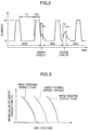
- Fig. 2 is a diagram showing the current at time of welding, in which the axis of abscissas represents time and the axis of ordinates represents current.
- a large current (pulse current) I p is outputted during the period of the pulse width P w and a base current I b is outputted during the base period T b following the period of the pulse width P w as shown, thereby to perform welding.
- the pulse current I p is outputted based on the pulse voltage V p which is set by the pulse voltage setting unit 12 and the base current I b is outputted based on the base voltage V b which is set by the base voltage setting unit 13 as described above. Further, basic output periods thereof are determined by set values P w and T b of the pulse width setting unit 15 and the base time setting unit 17, respectively.
- an irregular triangular wave is generated in the welding current 8 as shown in the figure by arc length self-control operation in the power source for welding having a constant voltage characteristic.
- the current increase portion of this triangular wave corresponds to the short circuit period (short circuit time) T s .
- Such short circuit time T s has a relative length as illustrated depending on the generating state of the short circuit.
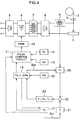
- the relationship between the short circuit time T s and the arc voltage is shown in Fig. 3 with the feeding speed of the welding wire as a parameter.
- Fig. 3 is a diagram explaining the short circuit time T s , in which the axis of ordinates represents the arc voltage (which is determined by the base time T b ) and the axis of abscissas represents the mean value of the short circuit time T s .
- the solid line indicates the mean value of the short circuit time T s in case the welding wire feeding speed is low
- a broken line indicates the mean value of the short circuit time T s in case the welding wire feeding speed is high
- a dotted line indicates the mean value of the short circuit time T s in case the welding wire feeding speed lies in-between.
- the mean value in a predetermined period of the short circuit time T s decreases with the increase of the arc voltage, and, when a predetermined arc voltage is exceeded, the short circuit is not generated, but the mean value of the short circuit time T s becomes 0. Namely, since the distance between the low end surface of the droplet and the base metal 1 is large when the arc voltage is high, no short circuit is generated. Further, it is comprehended that the relationship between the arc voltage and the mean value of the short circuit time T s remains almost the same even if the welding wire feeding speed is changed, and although the arc voltage that the short circuit becames no longer produced due to the welding wire feeding speed is different, there is no by difference in the tendency thereof.
- the short circuit time T s has been explained above. It may be concluded from the foregoing that, when the pulse voltage V p , the base voltage V b , and the pulse width P w are set in accordance with the material quality and the diameter of the welding wire 2 to be used, and the welding wire feeding speed (which relates to welding current), the arc voltage (which relates to base time T b ) in accordance with the welding work are selected, and the target value T j of the short circuit time T s is selected, and the short circuit time T s and the target value T j are compared with each other thereafter (the integrated value of the difference between both is used as described above in the present embodiment) and the short circuit time T s is brought to close to the target value T j , it is possible to always maintain an appropriate short circuit state, such as a state that a minute short circuit in a very short time is not produced, automatically even when an erroneous arc voltage setting has been made or even when a change in welding conditions, disturbance for the arc condition or
- the condition for obtaining a predetermined welding quality is not limited to one, but there are various conditions. Further, the arc state (welding conditions) that is easy to work is different depending on a worker who performs welding work practically. Since the target value T j is a value for determining which is better, the arc voltage is set higher (the short circuit time T s is short) or the arc voltage is set lower (the short circuit time T s is long), it is desirable to make the target value T j freely selectable by a worker from a viewpoint of convenience in use for the worker.
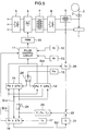
- a pulsed arc welding apparatus shown in Fig. 4 from what is shown in Fig. 1 exists in that the base time regulator 16 and the selection switch 24 shown in Fig. 1 are nonexistent. Namely, the integrated/mean value of the difference between the short circuit time T s and the target value T j from the integrated/mean value calculator 23 is supplied directly to the pulse width regulator 14. Further, a signal showing during the base time is supplied to the pulse control circuit 11 from the base time setting unit 17, and on the other hand, a signal showing the base period is supplied to the short time setting unit 21.
- the base time setting unit 17 sends a signal showing that the base period is ended to the pulse width regulator 14, the pulse period is started with the signal, and a signal showing during the pulse period is sent to the pulse control circuit 11.
- a predetermined pulse period P w ⁇ P w
- the end signal thereof is sent from the pulse width regulator 14 to the base time setting unit 17, and the base time setting unit 17 sends a signal showing the base period to the pulse control circuit 11.
- FIG. 5 Another embodiment of a pulsed arc welding apparatus is shown in Fig. 5.
- the difference of the pulsed arc welding apparatus shown in Fig. 5 from what is shown in Fig. 1 is that a pulse width regulator 14' and a selection switch 24' are added further to what is shown in Fig. 1.
- a pulse width regulator 14' and a selection switch 24' are added further to what is shown in Fig. 1.
- the selection switch 24' is changed over to the side of the pulse width regulator 14', and the pulse width regulator 14' decreases the pulse width P w supplied through the selection switch 24' by a value ⁇ P w conversely to the integration by the pulse width regulator 14 when the integrated value ⁇ (T s -T j ) supplied through the selection switch 24 is positive, and the pulse width regulator 14' increases the pulse width P w from the selection switch 24' by the value ⁇ P w when the integrated value ⁇ (T s -T j ) is negative. Since other structures shown in Fig. 5 are the same as those shown in Fig. 1, description thereof is omitted.
- a step 60 respective values are set to the pulse voltage setting unit 12, the base voltage setting unit 13, the pulse width setting unit 15, the base time setting unit 17 and the short circuit time setting unit 21, thus resetting a counter.
- Welding is started in a step 61.
- a pulse current and a base current shown in Fig. 2 flow in accordance with these respective set values.
- a stop signal S 20 is outputted to the short circuit time detector 20 from the pulse width regulator 14 thereby to stop the detection operation thereof during the period of the pulse width P w so that no detection is made in this case.
- the short circuit time detector 20 receives the induced voltage e 2 and obtains the time during which the induced voltage e 2 shows a negative value. This is the short circuit time.
- the base time regulator 16 outputs a signal S 21 for notifying that the base time T b has been started to the short circuit time setting unit 21, and in a step 64, the short circuit time setting unit 21 outputs the target value T j to the adder 22 during a predetermined time (the time in which generation of a short circuit is anticipated) from the input of the signal S 21 .
- the adder 22 receives the short circuit time T s from the short circuit time detector 20 and the target value T j from the short circuit time setting unit 21, computes the difference (T s -T j ) between both and outputs the result to the integrator 23.
- the difference (T s -T j ) between the short circuit time T s and the target value T j in the period (P w +T b ) is outputted from the adder 22 in every pulse period of (P w +T b ).
- the integrator 23 integrates the difference (T s -T j ) concerned successively and obtains the integrated value ⁇ (T s -T j ).
- the processing proceeds ahead.
- the integrated value ⁇ (T s -T j ) obtained by the integrated/mean value calculator 23 is outputted only to the base time regulator 16.
- a counter N is incremented, and, in a step 69, the counter is determined.
- the base time regulator 16 increases or decreases the present base time T b in accordance with the integrated value concerned when the integrated value ⁇ (T s -T j ) is inputted from the integrated/mean value calculator 23, and sets such new base time that the short circuit time T s becomes the target value T j , i.e., the integrated value ⁇ (T s -T j ) becomes 0. An instance of this operation will be given.
- time ⁇ T b in accordance with the integrated value ⁇ (T s -T j ) is added to the present base time so as to obtain new base time.
- the control constant ⁇ is determined taking the material quality of the welding wire 2, the velocity of response of control or the like into consideration. Then, counters N, ⁇ are reset in a step 73.
- the new base time T b00 obtained as described above is outputted to the pulse control circuit 11 in a step 72, and the pulse control circuit 11 outputs the ON/OFF command to a pulse width modulator 10 in accordance with this new base time T b00 , thus increasing or decreasing the base time. Further, in a period including this new base time T b00 , the short circuit time T s is detected again by means of the short circuit time detector 20 and the above-mentioned control operation is repeated.
- the above-mentioned means is one that controls the base time T b only with the selection switch 24 kept opened, but it is capable of performing more effective control by controlling the pulse width P w in addition to the base time T b .
- the selection switch 24 is closed.
- the integrated value ⁇ (T s -T j ) operated by the integrated/mean value calculator 23 is inputted to the base time regulator 16 and also to the pulse width regulator 14 at the same time.
- the pulse control circuit 11 also increases or decreases the pulse width P w similarly to the base time regulator 16.
- a step 75 conversely to the base time regulator 16 the pulse width P w is increased (P w + ⁇ P w ) by a value ⁇ P w in accordance with the integrated value ⁇ (T s -T j ) in case the integrated value ⁇ (T s -T j ) is positive, and the pulse width P w is decreased (P w - ⁇ P w ) by the value ⁇ P w in accordance with the integrated value ⁇ (T s -T j ) in case the integrated value ⁇ (T s -T j ) is negative.
- the pulse width P w is increased (P w + ⁇ P w ) by a value ⁇ P w in accordance with the integrated value ⁇ (T s -T j ) in case the integrated value ⁇ (T s -T j ) is positive, and the pulse width P w is decreased (P w - ⁇ P w ) by the value ⁇ P w in accord
- a step 77 it is recommended in a step 77 to decrease the pulse width P w by a value ⁇ P w when the integrated value ⁇ (T s -T j ) is positive and the pulse width P w is increased by the value ⁇ P w when the integrated value ⁇ (T s -T j ) is negative conversely to the above.
- This is carried out by making close the selection switch 24' to the pulse width regulator 14'.
- a Table 1 shown below shows the result of welding in which the apparatus shown in Fig. 1 has been used.
- the initial arc voltage has been varied within a range of an proper value ⁇ 3 V, but the arc voltage has been converged to proper arc voltage automatically in every case.
- a method of controlling the base time T b only and a method of performing automatic control in which the pulse width P w is increased when the integrated value ⁇ (T s -T j ) is positive and the pulse width P w is decreased when the integrated value ⁇ (T s -T j ) is negative along with automatic control of the base time T b have been examined as the control method, but satisfactory results have been obtained in either control method.
- a Table 2 below shows another result of welding.
- satisfactory results have also been obtained in either case of automatic control of the base time and automatic control of the base time and the pulse width.
- a Table 3 below shows another result of welding.
- the welding conditions are set the same as the Table 1, the automatic control of the base time and the automatic control of the pulse width are performed at the same time, and, in the automatic control of the pulse width, the pulse width Pw is decreased when the integrated value ⁇ (T s -T j ) is positive and the pulse width P w is increased when the integrated value ⁇ (T s -T j ) is negative.
- the arc voltage was all converged to proper arc voltage irrespective of the initial set value thereof.
- pulsed arc welding of a constant voltage system has been explained in the description of the present embodiment.
- the present invention is also applicable to pulsed arc welding of a constant current system.
- the short circuit time has been described citing an instance of using the integrated value ⁇ (T s -T j ), i.e., an instance in which the integrated value of the short circuit time is compared with a predetermined value (integrated value of the target value T j ), but it may also be arranged so that only the short circuit time T s is integrated and the mean value thereof is compared with the target value T j .
Landscapes
- Engineering & Computer Science (AREA)
- Physics & Mathematics (AREA)
- Plasma & Fusion (AREA)
- Mechanical Engineering (AREA)
- Arc Welding Control (AREA)
- Arc Welding In General (AREA)
- Generation Of Surge Voltage And Current (AREA)
Abstract
Description
- The present invention relates to a pulsed arc welding method and apparatus in which a droplet of a consumable electrode is transferred to a base metal in gas shield.
- There is a pulsed arc welding apparatus disclosed in JP-A-6-23547 as this sort of technique. In this apparatus, a short circuit generated by that a wire and a base metal come into contact with each other by means of the droplet of the wire is detected, the timing of generation is decided whether it is too early, appropriate or too late for the pulse period, and pulse parameters are set automatically so that a short circuit is made properly.
- It is an object of the present invention to provide a pulsed arc welding method and apparatus capable of always maintaining a proper arc state even when short circuit generation is changed.
- In order to achieve the above-mentioned object, a first aspect of the present invention exists in that a pulsed arc welding method detects the amount of time when a short circuit is being generated by melting of the consumable electrode, and controls an arc length so that a mean value or an integrated value of this amount of time shows an optional set value.
- When the mean value or the integrated value of the short circuit time is larger than the optional set value, the supply time of a base current is decreased in accordance with the difference therebetween, and, when the value of the short circuit time is smaller, the supply time of the base current is increased. In this way, it is possible to maintain the arc length in an optimum state only by controlling the supply time of the base current.
- When the mean value or the integrated value of the short circuit time is larger than the optional set value, the supply time of the base current is decreased and the supply period of the pulse current is increased at the same time in accordance with the difference therebetween and, when the mean value or the integrated value is smaller, the supply time of the base current is increased and the supply period of the pulse current is decreased at the same time. In this manner, the arc length is maintained in an optimum state with the supply time of the base current and the supply period of the pulse current.
- When it is required to compensate for resistance generation of heat produced when the consumable electrode projects beyond a predetermined length, respective supply periods of the base current and the pulse current are decreased in case the mean value or the integrated value of the short circuit time is larger than an optional set value, in accordance with the difference therebetween, and respective supply periods of the base current and the pulse current are increased in case they are smaller than the optional set value.
- When the mean value or the integrated value of the short circuit time is larger than an optional set value, the supply period of the pulse current is decreased in accordance with the difference therebetween, and, when it is smaller than the optional set value, the supply period of the pulse current is increased. In this manner, it is also possible to maintain the arc length in an optimum state by controlling the supply period of the pulse current.
- A second aspect of the present invention exists in that a pulsed arc welding apparatus comprises a short circuit detecting circuit for detecting the amount of time when a short circuit is being produced between a consumable electrode and a base metal by melting of the consumable electrode, a comparison circuit for comparing the integrated value or the mean value of the short circuit generating time detected by the short circuit detecting circuit with an optional set value, and a control circuit for controlling at least either one of the supply time of the pulse current and the supply time of the base current in accordance with the result of comparison by the comparison circuit.
- The comparison circuit has a base time setting unit for setting the supply time of the base current, a pulse width setting unit for setting the supply time of the pulse current, an adder for obtaining the difference between the short circuit time detected by the short circuit detecting circuit and the predetermined short circuit set time, an integrated/mean value calculator for calculating the integrated value or the mean value of the difference sent from the adder, a base time regulator for increasing or decreasing the supply time of the base current from the base time setting unit in accordance with the integrated value or the mean value so as to obtain the time for ending to supply the base current, a selection switch which closes when the integrated value or the mean value is received from the integrated/mean value calculator, and a pulse width regulator for increasing or decreasing the supply time of the pulse current from the pulse width setting unit in accordance with the integrated value or the mean value so as to obtain the time for terminating the supply of the pulse current. With this, the supply time of the pulse current and the base current is controlled thereby to maintain the arc length in an optimum state.
- Further, the comparison means has a base time setting unit for setting the supply time of the base current, a pulse width setting unit for setting the supply time of the pulse current, an adder for obtaining the difference between the short circuit time detected by the short circuit detecting circuit and the predetermined short circuit setting time, an integrated/mean value calculator for calculating the integrated value or the mean value of the difference sent from the adder, and a pulse width regulator for increasing or decreasing the supply time of the pulse current from the pulse width setting unit in accordance with the integrated value or the mean value so as to obtain the time for terminating the supply of the pulse current. With this, it is possible to maintain the arc length in an optimum state only by controlling the supply time of the pulse current.
- Furthermore, the comparison means has a base time setting unit for setting the supply time of the base current, a pulse width setting unit for setting the supply time of the pulse current, an adder for obtaining the difference between the short circuit time detected by the short circuit detecting circuit and the predetermined short circuit setting time, an integrated/mean value calculator for calculating the integrated value or the mean value of the difference sent from the adder, a base time regulator for increasing or decreasing the supply time of the base current from the base time setting unit in accordance with the integrated value or the mean value so as to obtain the time for ending to supply the base current, a first selection switch which is closed when the integrated value or the mean value is received from the integrated/mean value calculator, a first pulse width regulator for receiving the pulse current supply time from the pulse width setting unit in accordance with the integrated value or the mean value when a second selection switch is in a first state, decreasing the pulse width when the integrated value or the mean value shows a positive value and increasing the pulse width when the integrated value or the mean value shows a negative value, and a second pulse width regulator for receiving the pulse current supply time from the pulse width setting unit in accordance with the integrated value or the mean value when the second selection switch is in a second state, increasing the pulse width when the integrated value or the mean value shows a positive value and decreasing the pulse width when the integrated value or the mean value shows a negative value. With this, it is possible to select necessity or unecessity of compensation for resistance generation of heat produced by projection of a consumable electrode.
-
- Fig. 1 is a block diagram showing a first embodiment of a pulsed arc welding apparatus according to the present invention;
- Fig. 2 is a waveform diagram showing a current at time of welding;
- Fig. 3 is an explanatory diagram for explaining short circuit time;
- Fig. 4 is a block diagram showing another embodiment of a pulsed arc welding apparatus according to the present invention;
- Fig. 5 is a block diagram showing still another embodiment of a pulsed arc welding apparatus according to the present invention; and
- Fig. 6 is a flow chart for explaining a pulsed arc welding method according to the present invention.
- Fig. 1 is a block diagram of a pulsed arc welding apparatus in which a pulsed arc welding method is executed according to an embodiment of the present invention. In Fig. 1, a
reference numeral 1 represents a base metal, 2 a welding wire, and 3 a welding wire feed roller for feeding the welding wire at a predetermined speed. 5 indicates a primary rectifier for converting commercial alternating current to direct current working as a power source for welding, and 6 indicates an inverter circuit. Thisinverter circuit 6 is constituted using a switching element such as a field effect transistor (FET), and converts direct current outputted from theprimary rectifier 5 into predetermined alternating current. 7 represents a transformer, 8 represents a secondary rectifier for rectifying an alternating current output of thetransformer secondary rectifier 8 and supplying the output to the welding wire. A secondary winding is applied to the directcurrent reactor 9, and detects a short circuit generated when the point of thewelding wire 2 and thebase metal 1 come into contact with each other by the droplet of the welding wire during welding. - 10 represents a pulse width modulator (PWM) for determining ON/OFF time of the
inverter circuit PWM 10. 12 represents a pulse voltage setting unit for setting pulse voltage Vp for generating a pulse current in pulsed arc welding, and 13 represents a base voltage setting unit for setting base voltage Vb for generating the base current in a similar manner, and these respective voltage Vp and Vb are outputted to thepulse control circuit 11. 14 represents a pulse width regulator for regulating a pulse width (a pulse voltage application period) in pulsed arc welding, 15 represents a pulse width setting unit for setting a pulse width Pw concerned, 16 represents a base time regulator for also regulating the base time (a base voltage application period) in pulsed arc welding, and 17 represents a base time setting unit for setting base time Tb concerned. - In this way, the base time Tb is started when it is detected that the pulse width Pw is ended, and the pulse width Pw is started when it is detected that the base time Tb is ended (which is related to a period end signal S14 of the pulse width and a period end signal S16 of the base time). The
pulse control circuit 11 is operated so that outputs determined by pulse voltage Vp in the period of the pulse width Pw and determined by base voltage Vb in the period of the base time may be obtained. - 20 represents a short circuit time detector for detecting continuation time of short circuit Ts described above generated during welding. This short
circuit time detector 20 receives induced voltage generated in the secondary winding applied to the directcurrent reactor 9 thereby to detect the short circuit time Ts. The short circuit time Ts and the induced voltage concerned will be described later. 21 represents a short circuit time setting unit for setting a target value Tj of the short circuit time Ts, 22 represents an adder for receiving the short circuit time Ts detected by the shortcircuit time detector 20 and the target value Tj which has been set in the short circuittime setting unit 21 and computing the difference (Ts-Tj) between both, 23 represents an integrated/mean value calculator for adding up [Σ(Ts-Tj)] the output of theadder mean value calculator 23 into thepulse width regulator 14 and selecting whether the pulse width Pw is to be regulated or not. Besides, the integrated/mean value calculator 23 is illustrated in Fig. 1 so as to obtain the integrated value, but the mean value is obtainable when it is used, by dividing the integrated value by predetermined time or number of times. - Here, the above-mentioned short circuit time Ts will be explained with reference to Fig. 2 and Fig. 3. Fig. 2 is a diagram showing the current at time of welding, in which the axis of abscissas represents time and the axis of ordinates represents current. In pulsed arc welding, a large current (pulse current) Ip is outputted during the period of the pulse width Pw and a base current Ib is outputted during the base period Tb following the period of the pulse width Pw as shown, thereby to perform welding. In the present embodiment, the pulse current Ip is outputted based on the pulse voltage Vp which is set by the pulse
voltage setting unit 12 and the base current Ib is outputted based on the base voltage Vb which is set by the basevoltage setting unit 13 as described above. Further, basic output periods thereof are determined by set values Pw and Tb of the pulsewidth setting unit 15 and the basetime setting unit 17, respectively. - In case the above-mentioned short circuit is produced when welding is being executed in the embodiment described above, an irregular triangular wave is generated in the
welding current 8 as shown in the figure by arc length self-control operation in the power source for welding having a constant voltage characteristic. The current increase portion of this triangular wave corresponds to the short circuit period (short circuit time) Ts. Such short circuit time Ts has a relative length as illustrated depending on the generating state of the short circuit. The relationship between the short circuit time Ts and the arc voltage is shown in Fig. 3 with the feeding speed of the welding wire as a parameter. - Fig. 3 is a diagram explaining the short circuit time Ts, in which the axis of ordinates represents the arc voltage (which is determined by the base time Tb) and the axis of abscissas represents the mean value of the short circuit time Ts. In Fig. 3, the solid line indicates the mean value of the short circuit time Ts in case the welding wire feeding speed is low, a broken line indicates the mean value of the short circuit time Ts in case the welding wire feeding speed is high, and a dotted line indicates the mean value of the short circuit time Ts in case the welding wire feeding speed lies in-between. As it is apparent from Fig. 3, the mean value in a predetermined period of the short circuit time Ts decreases with the increase of the arc voltage, and, when a predetermined arc voltage is exceeded, the short circuit is not generated, but the mean value of the short circuit time Ts becomes 0. Namely, since the distance between the low end surface of the droplet and the
base metal 1 is large when the arc voltage is high, no short circuit is generated. Further, it is comprehended that the relationship between the arc voltage and the mean value of the short circuit time Ts remains almost the same even if the welding wire feeding speed is changed, and although the arc voltage that the short circuit becames no longer produced due to the welding wire feeding speed is different, there is no by difference in the tendency thereof. - The short circuit time Ts has been explained above. It may be concluded from the foregoing that, when the pulse voltage Vp, the base voltage Vb, and the pulse width Pw are set in accordance with the material quality and the diameter of the
welding wire 2 to be used, and the welding wire feeding speed (which relates to welding current), the arc voltage (which relates to base time Tb) in accordance with the welding work are selected, and the target value Tj of the short circuit time Ts is selected, and the short circuit time Ts and the target value Tj are compared with each other thereafter (the integrated value of the difference between both is used as described above in the present embodiment) and the short circuit time Ts is brought to close to the target value Tj, it is possible to always maintain an appropriate short circuit state, such as a state that a minute short circuit in a very short time is not produced, automatically even when an erroneous arc voltage setting has been made or even when a change in welding conditions, disturbance for the arc condition or the like are produced. - Here, the determination of the target value Tj of the short circuit time Ts will be explained. In the pulsed arc welding, the condition for obtaining a predetermined welding quality is not limited to one, but there are various conditions. Further, the arc state (welding conditions) that is easy to work is different depending on a worker who performs welding work practically. Since the target value Tj is a value for determining which is better, the arc voltage is set higher (the short circuit time Ts is short) or the arc voltage is set lower (the short circuit time Ts is long), it is desirable to make the target value Tj freely selectable by a worker from a viewpoint of convenience in use for the worker.
- Next, another embodiment of a pulsed arc welding apparatus will be explained with reference to Fig. 4. The difference of the pulsed arc welding apparatus shown in Fig. 4 from what is shown in Fig. 1 exists in that the
base time regulator 16 and theselection switch 24 shown in Fig. 1 are nonexistent. Namely, the integrated/mean value of the difference between the short circuit time Ts and the target value Tj from the integrated/mean value calculator 23 is supplied directly to thepulse width regulator 14. Further, a signal showing during the base time is supplied to thepulse control circuit 11 from the basetime setting unit 17, and on the other hand, a signal showing the base period is supplied to the shorttime setting unit 21. Further, the basetime setting unit 17 sends a signal showing that the base period is ended to thepulse width regulator 14, the pulse period is started with the signal, and a signal showing during the pulse period is sent to thepulse control circuit 11. When a predetermined pulse period (Pw±ΔPw) is ended, the end signal thereof is sent from thepulse width regulator 14 to the basetime setting unit 17, and the basetime setting unit 17 sends a signal showing the base period to thepulse control circuit 11. With this, it is possible to control the arc length only by regulating the pulse width Pw. Since other structures are the same as those of what is shown in Fig. 1, description thereof is omitted. - Furthermore, another embodiment of a pulsed arc welding apparatus is shown in Fig. 5. The difference of the pulsed arc welding apparatus shown in Fig. 5 from what is shown in Fig. 1 is that a pulse width regulator 14' and a selection switch 24' are added further to what is shown in Fig. 1. With this, when it is required to compensate for resistance generation of heat due to the projected length of the
welding wire 2 in addition to control the arc length with the base time Tb and the pulse width Pw as explained with reference to Fig. 1, the selection switch 24' is changed over to the side of the pulse width regulator 14', and the pulse width regulator 14' decreases the pulse width Pw supplied through the selection switch 24' by a value ΔPw conversely to the integration by thepulse width regulator 14 when the integrated value Σ(Ts-Tj) supplied through theselection switch 24 is positive, and the pulse width regulator 14' increases the pulse width Pw from the selection switch 24' by the value ΔPw when the integrated value Σ(Ts-Tj) is negative. Since other structures shown in Fig. 5 are the same as those shown in Fig. 1, description thereof is omitted. - Next, the operation of the present embodiment shown in Fig. 1 will be described based on Fig. 6. Besides, the apparatuses shown in Fig. 4 and Fig. 5 will be described later. First, in a
step 60, respective values are set to the pulsevoltage setting unit 12, the basevoltage setting unit 13, the pulsewidth setting unit 15, the basetime setting unit 17 and the short circuittime setting unit 21, thus resetting a counter. Welding is started in astep 61. At the start, a pulse current and a base current shown in Fig. 2 flow in accordance with these respective set values. - Induced voltage is generated in the secondary winding of the direct
current reactor 9 during welding. When it is assumed that the inductance of the secondary winding concerned is L2, a current passing therethrough is i, and the time is t, the induced voltage e2 is expressed by the following expression.
- When a short circuit is generated by a droplet, the induced voltage e2 shows a negative value since the current increases during the short circuit period, and, when the short circuit is opened, the induced voltage shows a positive value since the current decreases. However, since the induced voltage e2 also shows a negative value at the leading period of pulse voltage Vp, in a
step 62, a stop signal S20 is outputted to the shortcircuit time detector 20 from thepulse width regulator 14 thereby to stop the detection operation thereof during the period of the pulse width Pw so that no detection is made in this case. Then, when the pulse period is ended, in astep 63, the shortcircuit time detector 20 receives the induced voltage e2 and obtains the time during which the induced voltage e2 shows a negative value. This is the short circuit time. - On the other hand, the
base time regulator 16 outputs a signal S21 for notifying that the base time Tb has been started to the short circuittime setting unit 21, and in astep 64, the short circuittime setting unit 21 outputs the target value Tj to theadder 22 during a predetermined time (the time in which generation of a short circuit is anticipated) from the input of the signal S21. In astep 65, theadder 22 receives the short circuit time Ts from the shortcircuit time detector 20 and the target value Tj from the short circuittime setting unit 21, computes the difference (Ts-Tj) between both and outputs the result to theintegrator 23. Namely, the difference (Ts-Tj) between the short circuit time Ts and the target value Tj in the period (Pw+Tb) is outputted from theadder 22 in every pulse period of (Pw+Tb). In astep 66, theintegrator 23 integrates the difference (Ts-Tj) concerned successively and obtains the integrated value Σ(Ts-Tj). In astep 67, when the base time has been ended, the processing proceeds ahead. In astep 70, when theselection switch 24 is kept opened, the integrated value Σ(Ts-Tj) obtained by the integrated/mean value calculator 23 is outputted only to thebase time regulator 16. This is what is called a case that the arc length is controlled only by the base time Tb. Here, in astep 68, a counter N is incremented, and, in astep 69, the counter is determined. When the counter shows the maximum value, insteps base time regulator 16 increases or decreases the present base time Tb in accordance with the integrated value concerned when the integrated value Σ(Ts-Tj) is inputted from the integrated/mean value calculator 23, and sets such new base time that the short circuit time Ts becomes the target value Tj, i.e., the integrated value Σ(Ts-Tj) becomes 0. An instance of this operation will be given. Now, when it is assumed that the present base time is Tb00 and a control constant is α, the operation of new base time Tb00 is performed in accordance with the following expression.
- Namely, when the integrated value Σ(Ts-Tj) is positive (the integrated value of the short circuit time Ts is larger than the integrated value of the target value Tj), it is sufficient to decrease the mean value of the short circuit time Ts. For such a purpose, it is apparent to increase the arc voltage as it is apparent from Fig. 3. Thus, time ΔTb in accordance with the integrated value Σ(Ts-Tj) is decreased from the present base time so as to obtain new base time. Conversely, when the integrated value Σ(Ts-Tj) is negative, time ΔTb in accordance with the integrated value Σ(Ts-Tj) is added to the present base time so as to obtain new base time. Besides, the control constant α is determined taking the material quality of the
welding wire 2, the velocity of response of control or the like into consideration. Then, counters N, Σ are reset in astep 73. - The new base time Tb00 obtained as described above is outputted to the
pulse control circuit 11 in astep 72, and thepulse control circuit 11 outputs the ON/OFF command to apulse width modulator 10 in accordance with this new base time Tb00, thus increasing or decreasing the base time. Further, in a period including this new base time Tb00, the short circuit time Ts is detected again by means of the shortcircuit time detector 20 and the above-mentioned control operation is repeated. - The above-mentioned means is one that controls the base time Tb only with the
selection switch 24 kept opened, but it is capable of performing more effective control by controlling the pulse width Pw in addition to the base time Tb. When such control is performed, theselection switch 24 is closed. By closing theselection switch 24, the integrated value Σ(Ts-Tj) operated by the integrated/mean value calculator 23 is inputted to thebase time regulator 16 and also to thepulse width regulator 14 at the same time. Thepulse control circuit 11 also increases or decreases the pulse width Pw similarly to thebase time regulator 16. When it is not required in astep 74 to compensate for the resistance generation of heat due to the extension length of thewelding wire 2, however, in astep 75, conversely to thebase time regulator 16 the pulse width Pw is increased (Pw+ΔPw) by a value ΔPw in accordance with the integrated value Σ(Ts-Tj) in case the integrated value Σ(Ts-Tj) is positive, and the pulse width Pw is decreased (Pw-ΔPw) by the value ΔPw in accordance with the integrated value Σ(Ts-Tj) in case the integrated value Σ(Ts-Tj) is negative. This is carried out by making close a selection switch 24' to thepulse width regulator 14. In astep 76, the arc length is controlled with the base time Tb00 and the pulse width (Pw±ΔPw). - When it is required to compensate for resistance generation of heat due to the extension length of the
welding wire 2, in astep 74, it is recommended in astep 77 to decrease the pulse width Pw by a value ΔPw when the integrated value Σ(Ts-Tj) is positive and the pulse width Pw is increased by the value ΔPw when the integrated value Σ(Ts-Tj) is negative conversely to the above. This is carried out by making close the selection switch 24' to the pulse width regulator 14'. This corresponds to the pulsed arc welding apparatus shown in Fig. 5. Since the pulsed arc welding apparatus shown in Fig. 4 can be comprehended easily from the operation explained based on Fig. 1, description thereof is omitted. - Since it has been made in the present embodiment to regulate the base time or the base time and the pulse width so as to bring the short circuit time generated during welding closer to the target value, it is possible to always maintain an appropriate short circuit state automatically even when a change in the welding condition or disturbance on the arc state and so on are produced, thus making it possible to secure a high welding quality easily and to uniformalize the welding quality.
- Further, a considerable amount of skill has been required for setting the arc voltage in order to obtain an appropriate arc state in conventional pulsed arc welding. In the present embodiment, however, the skill of a worker is not required since inappropriate setting of the arc voltage is corrected automatically if any.
- Furthermore, it is required to set appropriate arc voltage in accordance with the welding current in conventional pulsed arc welding, but, since the short circuit state is controlled in the present embodiment, it is not required to vary setting in accordance with the welding current (wire feeding speed), and the burden is largely improved for a worker.
- A Table 1 shown below shows the result of welding in which the apparatus shown in Fig. 1 has been used. In this case, welding in which the welding current (i.e., welding wire feeding speed) and the initial voltage (i.e., the initial set value of the base time) has been performed using
JIS YGW 17 having a diameter of 1.2 mm for the welding wire and assuming that the pulse voltage Vp = 39 V, the base voltage Vb = 8.5 V, the pulse width Pw = 1.4 ms, the welding wire extension length (EXT) = 15 mm, the welding speed = 750 mm/min. and the target value Tj = 0.02 ms. Besides, the symbols "○", "△", "▲" and "X" in the table show goodness of the result of welding in this order, and "○" shows the best and "X" shows inferiority. (The same is applied to a Table 2 and a Table 3 shown later.)Table 1 Welding current (A) Initial arc voltage (V) No control Tb control (Tb+Pw) contrtol Convergent arc voltage (V) Decision Convergent arc voltage (V) Decision Convergent arc voltage (V) Decision 100 (3.5 m/min) 18.5 18.5 X 21.3∼21.5 ○ 20.8∼21.0 ○ 20.0 20.0 ▲ 21.0∼21.5 ○ 21.3∼21.5 ○ 21.5 21.5 ○ 21.0∼21.5 ○ 21.0∼21.5 ○ 23.0 23.0 ▲ 21.0∼21.3 ○ 21.5 ○ 24.5 24.5 X 21.0∼21.3 ○ 21.5 ○ 150 (5.3 m/min) 21.0 21.0 X 23.5∼24.0 ○ 24.5 ○ 22.5 22.5 ▲ 34.5∼24.0 ○ 24.0∼24.5 ○ 24.0 24.0 ○ 23.5∼24.0 ○ 23.2∼24.0 ○ 25.5 25.5 ▲ 23.5∼24.0 ○ 24.0∼24.2 ○ 27.0 27.0 X 23.5∼24.0 ○ 23.8∼24.0 ○ 200 (7.7 m/min) 22.5 22.5 X 25.5∼26.0 ○ 25.0, 25.5 ○ 24.0 24.0 ▲ 25.5∼26.0 ○ 25.0∼25.5 ○ 25.5 25.5 ○ 25.3∼25.5 ○ 26.0 ○ 27.0 27.0 ▲ 25.8∼26.0 ○ 25.8∼26.0 ○ 28.5 28.5 X 25.8∼26.0 ○ 25.8∼26.0 ○ 250 (8.7 m/min) 23.5 23.5 X 26.2∼26.5 ○ 26.5 ○ 25.0 25.0 ▲ 26.0 ○ 26.5 ○ 26.5 26.5 ○ 26.3∼26.5 ○ 26.0∼26.5 ○ 27.5 27.5 ▲ 26.0 ○ 28.5 ○ 28.5 28.5 X 26.0∼26.3 ○ 26.5 ○ 300 (11.8 m/min) 24.0 24.0 X 27.2∼27.5 ○ 28.5 ○ 25.0 25.0 ▲ 27.2∼27.5 ○ 28.2 ○ 26.0 26.0 △ 27.5 ○ 28.0 ○ 27.0 27.0 ○ 27.2∼27.5 ○ 27.8 ○ Welding wire: JIS YGV17·φ1.2 mm
Tj = 0.02 ms, Vp = 39 V, Vb = 8.5 V, Pw = 1.4 ms,
Ext = 15 mm, Welding speed = 750 mm/min - In respective welding currents, the initial arc voltage has been varied within a range of an proper value ±3 V, but the arc voltage has been converged to proper arc voltage automatically in every case. Besides, a method of controlling the base time Tb only and a method of performing automatic control in which the pulse width Pw is increased when the integrated value Σ(Ts-Tj) is positive and the pulse width Pw is decreased when the integrated value Σ(Ts-Tj) is negative along with automatic control of the base time Tb have been examined as the control method, but satisfactory results have been obtained in either control method.
- A Table 2 below shows another result of welding. In this case, welding similar to the case of the Table 1 has been performed using
JIS YGW 15 having a diameter of 1.6 mm for the welding wire and assuming that the pulse voltage Vp = 43 V, the base voltage Vb = 10 V, the pulse width Pw = 1.9 ms, the welding wire extension length (EXT) = 20 mm, the welding speed = 750 mm/min, and the target value Tj = 0.03 ms. In this case, satisfactory results have also been obtained in either case of automatic control of the base time and automatic control of the base time and the pulse width.Table 2 Welding current (A) Initial arc voltage (V) No control Tb control (Tb+Pw) contrtol Convergent arc voltage (V) Decision Convergent arc voltage (V) Decision Convergent arc voltage (V) Decision 150 (2.7 m/min) 19.5 19.5 X 22.5∼23.0 ○ 22.5∼23.0 ○ 21.0 21.0 ▲ 22.5∼23.0 ○ 22.5 ○ 22.5 22.5 ○ 22.5 ○ 22.0∼22.5 ○ 24.0 24.0 ▲ 22.5∼23.0 ○ 22.0∼22.5 ○ 25.5 25.5 X 22.5∼23.0 ○ 22.5∼23.0 ○ 200 (3.5 m/min) 21.0 21.0 X 22.8∼23.2 ○ 23.0∼23.5 ○ 22.5 22.5 ▲ 23.0∼23.5 ○ 23.0∼23.5 ○ 24.0 24.0 ○ 22.5∼23.0 ○ 23.0∼23.5 ○ 25.5 25.5 ▲ 22.5∼23.0 ○ 23.5∼24.0 ○ 27.0 27.0 X 23.0∼23.5 ○ 23.5∼24.0 ○ 250 (5.3 m/min) 22.0 22.0 X 25.5∼26.0 ○ 25.0, 25.5 ○ 23.5 23.5 ▲ 24.5∼25.0 ○ 24.5∼25.0 ○ 25.0 25.0 ○ 25.0∼25.3 ○ 25.0∼25.5 ○ 26.5 26.5 ▲ 24.5∼25.0 ○ 24.5∼25.0 ○ 28.0 28.0 X 25.0∼25.5 ○ 24.5∼25.0 ○ 300 (5.8 m/min) 23.0 23.0 X 25.5∼26.0 ○ 26.0∼26.3 ○ 24.5 24.5 ▲ 25.8∼26.3 ○ 25.8∼26.2 ○ 26.0 26.0 ○ 25.5∼26.0 ○ 26.0∼26.2 ○ 27.5 27.5 ▲ 25.5∼26.0 ○ 26.0∼26.2 ○ 29.0 29.0 X 25.5∼26.0 ○ 26.0∼26.3 ○ 350 (6.5 m/min) 24.0 24.0 X 26.5∼26.8 ○ 26.8∼27.0 ○ 25.5 25.5 ▲ 26.5∼26.8 ○ 26.5∼27.0 ○ 27.0 27.0 ○ 26.5∼27.0 ○ 26.0∼26.5 ○ 28.5 28.5 ▲ 26.8∼27.0 ○ 26.5 ○ 30.0 30.0 X 27.0∼27.2 ○ 26.0∼26.5 ○ Welding wire: JIS YGV17·φ1.6 mm
Tj = 0.03 ms, Vp = 43 V, Vb = 10 V, Pw = 1.9 ms,
Ext = 20 mm, Welding speed = 750 m/min - A Table 3 below shows another result of welding. In this case, the welding conditions are set the same as the Table 1, the automatic control of the base time and the automatic control of the pulse width are performed at the same time, and, in the automatic control of the pulse width, the pulse width Pw is decreased when the integrated value Σ(Ts-Tj) is positive and the pulse width Pw is increased when the integrated value Σ(Ts-Tj) is negative. In this case, it could also be confirmed that the arc voltage was all converged to proper arc voltage irrespective of the initial set value thereof.
Table 3 Initial arc set value (Tb) control (Tb+Pw) contrtol Set voltage (V) Tb (ms) Pw (ms) Convergent arc voltage (V) Tb (ms) Pw (ms) Convergent arc voltage (V) Tb (ms) Pw (ms) 21.0 7.8 1.6 24.3∼24.5 4.7 1.6 25.3 3.5 1.34 22.5 6.3 24.5∼25.0 4.4 25.0 3.9 1.40 24.0 5.4 24.0∼24.5 4.7 24.5 4.0 1.46 25.5 4.0 24.0∼24.5 4.8 24.5 5.0 1.66 27.0 3.5 24.0∼24.5 4.6 24.5 4.8 1.74 Welding wire: JIS YGV17·φ1.2 mm, Welding wire feeding speed = 5.3 m/min(≒ 150 A)
Welding speed = 750 mm/min, Ext = 15 mm, Vp = 39 V, Vb = 8.5 V, *Tj = 0.02 ms - Besides, pulsed arc welding of a constant voltage system has been explained in the description of the present embodiment. However, it is apparent that the present invention is also applicable to pulsed arc welding of a constant current system. Further, the short circuit time has been described citing an instance of using the integrated value Σ(Ts-Tj), i.e., an instance in which the integrated value of the short circuit time is compared with a predetermined value (integrated value of the target value Tj), but it may also be arranged so that only the short circuit time Ts is integrated and the mean value thereof is compared with the target value Tj.
Claims (11)
- A pulsed arc welding method for welding by supplying a pulse current and a base current alternately across a consumable electrode (2) and a base metal (1), comprising the steps of:detecting a time during which a short circuit produced by melting of said consumable electrode is generated; andcontrolling arc length so that one of a mean value and an integrated value of the time shows an optional set value.
- A pulsed arc welding method according to Claim 1, wherein said arc length is controlled so that when one of said mean value and said integrated value is larger than said optional set value, a supply time of said base current is decreased in accordance with difference therebetween, and, when one of said mean value and said integrated value is smaller than said optional set value, a supply time of said base current is increased in accordance with difference therebetween.
- A pulsed arc welding method according to Claim 1, wherein said arc length is controlled so that when one of said mean value and said integrated value is larger than said optional set value, a supply time of said base current is decreased and a supply period of said pulse current is increased simultaneously in accordance with difference therebetween, and when one of said mean value and said integrated value is smaller than said optional set value, a supply time of said base current is increased and a supply period of said pulse current is decreased simultaneously in accordance with difference therebetween.
- A pulsed arc welding method according to Claim 1, wherein said arc length is controlled so that when one of said mean value and said integrated value is larger than said optional set value, respective supply periods of said base current and said pulse current are decreased in accordance with difference therebetween, and when one of said mean value and said integrated value is smaller than said optional set value, respective supply periods of said base current and said pulse current are increased in accordance with difference therebetween.
- A pulsed arc welding method according to Claim 1, wherein said arc length is controlled so that when one of said mean value and said integrated value is larger than said optional set value, a supply period of said pulse current is increased in accordance with difference therebetween, and, when one of said mean value and said integrated value is smaller than said optional set value, a supply period of said pulse current is decreased in accordance with difference therebetween.
- A pulsed arc welding apparatus for welding by supplying a pulse current and a base current alternately across a consumable electrode (2) and a base metal (1), comprising:short circuit detecting means (9, 20) for detecting a time during which a short circuit produced by melting said consumable electrode across said consumable electrode (2) and said base metal (1) is generated;comparison means (20, 21, 22, 23) for comparing one of an integrated value and a mean value of a short circuit generating time detected by the short circuit detecting means with an optional set value; andcontrol means (11, 14, 16, 24) for controlling at least one of a supply time of said pulse current and a supply time of said base current in accordance with a result of the comparison by said comparison means.
- A pulsed arc welding apparatus according to Claim 6, wherein said comparison means comprises:a base time setting unit (17) for setting the supply time of the base current;a pulse width setting unit (15) for setting the supply time of the pulse current;an adder (22) for obtaining difference between a short circuit time (Ts) detected by said short circuit detecting means (20) and a predetermined short circuit setting time;an integrated/mean value calculator (23) for generating one of an integrated value and a mean value of the difference from said adder (22);a base time regulator (16) at least one of increasing and decreasing the supply time of said base current from said base time setting unit (17) in accordance with one of said integrated value and said mean value and obtaining a time of ending to supply the base current;a selection switch (24) which is closed when one of said integrated value and mean value from said integrated/mean value calculator (23) is received; anda pulse width regulator (14) for receiving one of said integrated value and said mean value through said selection switch (24), at least one of increasing and decreasing the supply time of said pulse current from said pulse width setting unit (15), and obtaining a time for terminating the supply of the pulse current.
- A pulsed arc welding apparatus according to Claim 6, wherein said comparison means comprises:a base time setting unit (17) for setting the supply time of the base current;a pulse width setting unit (15) for setting the supply time of the pulse current;an adder (22) for obtaining difference between a short circuit time detected by said short circuit detecting means (20) and a short circuit setting time calculated in accordance with the supply time of the base current from said base time setting unit (17);an integrated/mean value calculator (23) for generating one of an integrated value and a mean value of difference from said adder (22); anda pulse width regulator (14) at least one of increasing and decreasing the supply time of said pulse current from said pulse width setting unit (15) in accordance with one of said integrated value and mean value, and obtaining a time of terminating the supply of the pulse current.
- A pulsed arc welding apparatus according to Claim 6, wherein said comparison means comprises:a base time setting unit (17) for setting the supply time of the base current;a pulse width setting unit (15) for setting the supply time of the pulse current;an adder (22) for obtaining difference between a short circuit time (Ts) detected by said short circuit detecting means (20) and a predetermined short circuit setting time;an integrated/mean value calculator (23) for generating one of an integrated value and a mean value of the difference from said adder (22);a base time regulator (16) at least one of increasing and decreasing the supply time of said base current from said base time setting unit (17) in accordance with one of said integrated value and said mean value and obtaining a time of ending to supply the base current;a first selection switch (24) which is closed when one of said integrated value and mean value from said integrated/mean value calculator (23) is received;a first pulse width regulator (14) for receiving one of said integrated value and said mean value through said first selection switch (24), receiving said pulse current supply time from said pulse width setting unit (15) when a second selection switch (24') is in a first state, and decreasing a pulse width when one of said integrated value and said mean value is positive and increasing a pulse width when one of the integrated value and the mean value is negative; anda second pulse width regulator (14') for receiving one of said integrated value and said mean value through said first selection switch (24), receiving said pulse current supply time from said pulse width setting unit (15) when said second selection switch (24') is in a second state, and increasing a pulse width when one of said integrated value and said mean value is positive and decreasing a pulse width when one of the integrated value and the mean value is negative;
whereby said first and second pulse width regulators (14, 14') obtain a time for terminating the supply of the pulse current, respectively. - A pulsed arc welding apparatus according to Claim 6, wherein said short circuit detecting means, comparison means and control means are based on a constant voltage system.
- A pulsed arc welding apparatus according to Claim 6, wherein said short circuit detecting means, comparison means and control means are based on a constant current system.
Applications Claiming Priority (3)
| Application Number | Priority Date | Filing Date | Title |
|---|---|---|---|
| JP29564495A JP3206714B2 (en) | 1995-11-14 | 1995-11-14 | Pulse arc welding method and apparatus |
| JP295644/95 | 1995-11-14 | ||
| JP29564495 | 1995-11-14 |
Publications (2)
| Publication Number | Publication Date |
|---|---|
| EP0774317A1 true EP0774317A1 (en) | 1997-05-21 |
| EP0774317B1 EP0774317B1 (en) | 2002-02-20 |
Family
ID=17823326
Family Applications (1)
| Application Number | Title | Priority Date | Filing Date |
|---|---|---|---|
| EP96118265A Expired - Lifetime EP0774317B1 (en) | 1995-11-14 | 1996-11-14 | Pulsed arc welding method and apparatus |
Country Status (5)
| Country | Link |
|---|---|
| US (1) | US5824991A (en) |
| EP (1) | EP0774317B1 (en) |
| JP (1) | JP3206714B2 (en) |
| KR (1) | KR100475516B1 (en) |
| DE (1) | DE69619343T2 (en) |
Cited By (9)
| Publication number | Priority date | Publication date | Assignee | Title |
|---|---|---|---|---|
| DE19808383A1 (en) * | 1998-02-27 | 1999-09-02 | Volkswagen Ag | Method for MIG/MAG electric arc welding to join two or more components made of light metals or alloys |
| WO2007028854A1 (en) * | 2005-09-06 | 2007-03-15 | Kemppi Oy | Method and apparatus for welding |
| EP1779957A2 (en) | 2005-10-31 | 2007-05-02 | Lincoln Global, Inc. | Synergistic welding system |
| CN101486122A (en) * | 2008-01-15 | 2009-07-22 | 株式会社大亨 | Short circuit discrimination method for consumable electrode arc welding |
| US7812284B2 (en) | 2005-07-12 | 2010-10-12 | Lincoln Global, Inc. | Barium and lithium ratio for flux cored electrode |
| US8035059B2 (en) | 2003-10-23 | 2011-10-11 | Fronius International Gmbh | Method for controlling and/or adjusting a welding process |
| US8704135B2 (en) * | 2006-01-20 | 2014-04-22 | Lincoln Global, Inc. | Synergistic welding system |
| US9012808B2 (en) | 2005-02-25 | 2015-04-21 | Fronius International Gmbh | Method for controlling and/or regulating a welding apparatus, and welding apparatus |
| US9956638B2 (en) | 2004-10-06 | 2018-05-01 | Lincoln Global, Inc. | Electric arc welder for AC welding with cored electrode |
Families Citing this family (25)
| Publication number | Priority date | Publication date | Assignee | Title |
|---|---|---|---|---|
| FR2756036B1 (en) * | 1996-11-20 | 1999-01-08 | Dehon Sa Anciens Etablissement | METHOD FOR RE-TESTING A PACKAGING FILLED WITH AN ACTIVE FLUID AND A PROPELLANT AND APPARATUS FOR IMPLEMENTING THE METHOD |
| JPH10277740A (en) * | 1997-04-01 | 1998-10-20 | Kobe Steel Ltd | Pulse arc welding equipment |
| JP3231694B2 (en) * | 1998-01-27 | 2001-11-26 | 株式会社三社電機製作所 | Power supply for welding |
| US6087626A (en) * | 1998-02-17 | 2000-07-11 | Illinois Tool Works Inc. | Method and apparatus for welding |
| KR100415462B1 (en) * | 2001-02-14 | 2004-01-24 | 주식회사 세일 기전 | Pulse MAG arc Welding Method |
| US6794608B2 (en) * | 2001-10-30 | 2004-09-21 | Tri Tool Inc. | Welding current control system and method |
| BR0308219A (en) * | 2002-03-06 | 2004-12-21 | Lincoln Global Inc | Two stage welding machine and method of operating the same |
| KR100506854B1 (en) * | 2002-08-30 | 2005-08-08 | 한국전기연구원 | Pulse arc welding method |
| US9333580B2 (en) | 2004-04-29 | 2016-05-10 | Lincoln Global, Inc. | Gas-less process and system for girth welding in high strength applications |
| JP3844004B1 (en) * | 2005-05-31 | 2006-11-08 | 松下電器産業株式会社 | Pulse arc welding control method and pulse arc welding apparatus |
| CA2622134C (en) * | 2005-09-12 | 2013-12-24 | Esab Ab | Control method for mig/mag-welding and welding equipment applying this method |
| JP4807474B2 (en) * | 2009-06-19 | 2011-11-02 | パナソニック株式会社 | Consumable electrode arc welding method and consumable electrode arc welding apparatus |
| DE102009045689A1 (en) * | 2009-10-14 | 2011-04-28 | Endress + Hauser Conducta Gesellschaft für Mess- und Regeltechnik mbH + Co. KG | transmitters |
| EP2580017B1 (en) * | 2010-06-14 | 2014-04-16 | Esab AB | A method of automatically setting a welding parameter for mig/mag welding and a controller for performing the method |
| CN102441722B (en) * | 2010-09-30 | 2015-05-27 | 株式会社大亨 | Arc welding method |
| JP5071543B2 (en) * | 2010-10-04 | 2012-11-14 | 株式会社安川電機 | Arc welding apparatus and arc welding system |
| JP5808947B2 (en) * | 2011-05-23 | 2015-11-10 | 株式会社ダイヘン | Constriction detection control method for consumable electrode arc welding |
| KR101860947B1 (en) * | 2011-11-16 | 2018-05-25 | 현대중공업 주식회사 | Welding Arc Regeneration Expectation Method for Reduction Spatter |
| EP2961555A4 (en) * | 2013-02-28 | 2016-10-12 | United Technologies Corp | SYSTEM AND METHOD FOR LOW HEAT WELDING |
| WO2017135080A1 (en) * | 2016-02-04 | 2017-08-10 | パナソニックIpマネジメント株式会社 | Pulsed arc welding control method and pulsed arc welding device |
| US11370051B2 (en) * | 2018-10-30 | 2022-06-28 | Lincoln Global, Inc. | Time-based short circuit response |
| CN111230260A (en) * | 2018-11-28 | 2020-06-05 | 林肯环球股份有限公司 | Method for controlling an arc welding system to reduce spatter |
| US11311958B1 (en) * | 2019-05-13 | 2022-04-26 | Airgas, Inc. | Digital welding and cutting efficiency analysis, process evaluation and response feedback system for process optimization |
| CN115770928B (en) * | 2022-11-30 | 2025-10-28 | 唐山松下产业机器有限公司 | Arc length control method |
| CN116810090A (en) * | 2023-07-04 | 2023-09-29 | 唐山松下产业机器有限公司 | Energy compensation method and device for pulse welding |
Citations (5)
| Publication number | Priority date | Publication date | Assignee | Title |
|---|---|---|---|---|
| JPS5744472A (en) * | 1980-08-29 | 1982-03-12 | Mitsubishi Electric Corp | Pulse arc welding method |
| EP0342691A2 (en) * | 1988-05-19 | 1989-11-23 | Mitsubishi Denki Kabushiki Kaisha | Pulse arc discharge welding apparatus |
| JPH0623547A (en) | 1992-07-08 | 1994-02-01 | Toyota Motor Corp | Pulse arc welding equipment |
| EP0607819A1 (en) * | 1993-01-18 | 1994-07-27 | Toyota Jidosha Kabushiki Kaisha | Pulsed arc welding apparatus having a consumable electrode wire |
| US5406052A (en) * | 1989-02-28 | 1995-04-11 | Mitsubishi Denki Kabushiki Kaisha | Pulsed arc welding equipment |
Family Cites Families (7)
| Publication number | Priority date | Publication date | Assignee | Title |
|---|---|---|---|---|
| JPS574472A (en) * | 1980-06-11 | 1982-01-11 | Hitachi Ltd | Wheel structure for transportation vehicle |
| DE3213278A1 (en) * | 1981-04-10 | 1982-11-18 | Mitsubishi Denki K.K., Tokyo | SHORT-CIRCUIT ARC WELDING WELDING MACHINE |
| GB8306578D0 (en) * | 1983-03-10 | 1983-04-13 | Welding Inst | Short-circuit mig welding |
| US4647754A (en) * | 1984-04-10 | 1987-03-03 | Matsushita Electric Industrial Co., Ltd. | Consumable electrode type pulse arc welding machine |
| JPS61262469A (en) * | 1985-05-16 | 1986-11-20 | Toyota Motor Corp | Pulse arc welding machine |
| US4717807A (en) * | 1986-12-11 | 1988-01-05 | The Lincoln Electric Company | Method and device for controlling a short circuiting type welding system |
| US4889969A (en) * | 1987-04-28 | 1989-12-26 | Matsushita Electric Industrial Co., Ltd. | Reduced-spatter pulse arc welding machine for use with a consumable electrode |
-
1995
- 1995-11-14 JP JP29564495A patent/JP3206714B2/en not_active Expired - Lifetime
-
1996
- 1996-11-13 KR KR1019960053709A patent/KR100475516B1/en not_active Expired - Fee Related
- 1996-11-14 US US08/748,924 patent/US5824991A/en not_active Expired - Fee Related
- 1996-11-14 DE DE69619343T patent/DE69619343T2/en not_active Expired - Lifetime
- 1996-11-14 EP EP96118265A patent/EP0774317B1/en not_active Expired - Lifetime
Patent Citations (5)
| Publication number | Priority date | Publication date | Assignee | Title |
|---|---|---|---|---|
| JPS5744472A (en) * | 1980-08-29 | 1982-03-12 | Mitsubishi Electric Corp | Pulse arc welding method |
| EP0342691A2 (en) * | 1988-05-19 | 1989-11-23 | Mitsubishi Denki Kabushiki Kaisha | Pulse arc discharge welding apparatus |
| US5406052A (en) * | 1989-02-28 | 1995-04-11 | Mitsubishi Denki Kabushiki Kaisha | Pulsed arc welding equipment |
| JPH0623547A (en) | 1992-07-08 | 1994-02-01 | Toyota Motor Corp | Pulse arc welding equipment |
| EP0607819A1 (en) * | 1993-01-18 | 1994-07-27 | Toyota Jidosha Kabushiki Kaisha | Pulsed arc welding apparatus having a consumable electrode wire |
Non-Patent Citations (1)
| Title |
|---|
| PATENT ABSTRACTS OF JAPAN vol. 6, no. 117 (M - 139) 30 June 1982 (1982-06-30) * |
Cited By (15)
| Publication number | Priority date | Publication date | Assignee | Title |
|---|---|---|---|---|
| DE19808383A1 (en) * | 1998-02-27 | 1999-09-02 | Volkswagen Ag | Method for MIG/MAG electric arc welding to join two or more components made of light metals or alloys |
| EP1677941B2 (en) † | 2003-10-23 | 2011-10-12 | Fronius International GmbH | Method for controlling and/or adjusting a welding process |
| US8035059B2 (en) | 2003-10-23 | 2011-10-11 | Fronius International Gmbh | Method for controlling and/or adjusting a welding process |
| US9956638B2 (en) | 2004-10-06 | 2018-05-01 | Lincoln Global, Inc. | Electric arc welder for AC welding with cored electrode |
| US9012808B2 (en) | 2005-02-25 | 2015-04-21 | Fronius International Gmbh | Method for controlling and/or regulating a welding apparatus, and welding apparatus |
| US7812284B2 (en) | 2005-07-12 | 2010-10-12 | Lincoln Global, Inc. | Barium and lithium ratio for flux cored electrode |
| RU2415000C2 (en) * | 2005-09-06 | 2011-03-27 | Кемппи Ой | Method of welding and welding device |
| CN101282813B (en) * | 2005-09-06 | 2012-01-11 | 肯倍公司 | Method and apparatus for welding |
| WO2007028854A1 (en) * | 2005-09-06 | 2007-03-15 | Kemppi Oy | Method and apparatus for welding |
| EP1779957A3 (en) * | 2005-10-31 | 2009-06-17 | Lincoln Global, Inc. | Synergistic welding system |
| AU2006225197B2 (en) * | 2005-10-31 | 2009-04-23 | Lincoln Global, Inc. | Synergistic welding system |
| EP1779957A2 (en) | 2005-10-31 | 2007-05-02 | Lincoln Global, Inc. | Synergistic welding system |
| US8704135B2 (en) * | 2006-01-20 | 2014-04-22 | Lincoln Global, Inc. | Synergistic welding system |
| CN101486122A (en) * | 2008-01-15 | 2009-07-22 | 株式会社大亨 | Short circuit discrimination method for consumable electrode arc welding |
| CN101486122B (en) * | 2008-01-15 | 2013-07-03 | 株式会社大亨 | Short circuit discrimination method for consumable electrode arc welding |
Also Published As
| Publication number | Publication date |
|---|---|
| JPH09141430A (en) | 1997-06-03 |
| JP3206714B2 (en) | 2001-09-10 |
| DE69619343T2 (en) | 2002-09-19 |
| DE69619343D1 (en) | 2002-03-28 |
| KR970025814A (en) | 1997-06-24 |
| KR100475516B1 (en) | 2005-07-05 |
| EP0774317B1 (en) | 2002-02-20 |
| US5824991A (en) | 1998-10-20 |
Similar Documents
| Publication | Publication Date | Title |
|---|---|---|
| EP0774317B1 (en) | Pulsed arc welding method and apparatus | |
| JP3802832B2 (en) | Apparatus and method for controlling an electric arc welder | |
| US8502114B2 (en) | AC pulse arc welding method | |
| US9718142B2 (en) | Method and apparatus for welding with CV control | |
| EP0508281B1 (en) | Arc welding machine | |
| EP0607819B1 (en) | Pulsed arc welding apparatus having a consumable electrode wire | |
| JPS6264483A (en) | Method and device for adjusting welding current | |
| JP3018807B2 (en) | Consumable electrode type pulse arc welding equipment | |
| US5643475A (en) | Power supply apparatus | |
| JP2892198B2 (en) | Consumable electrode type AC pulse arc welding method | |
| JP3117513B2 (en) | Bipolar pulse arc welding equipment | |
| JPH062310B2 (en) | Pulse arc welding method | |
| JPH0938772A (en) | Ac self-shielded arc welding method | |
| JPS6044071B2 (en) | Control method and device for welding power source | |
| JP2978598B2 (en) | Pulse arc welding method | |
| US5124521A (en) | Method and apparatus for controlling welding current in resistance welding | |
| JP4459768B2 (en) | AC pulse arc welding welding current control method | |
| US20230311230A1 (en) | Cancellation of the effects of primary voltage variations | |
| JPH10175067A (en) | Self-shielded arc welding method | |
| JP2675624B2 (en) | AC TIG welding method and apparatus | |
| JP2985552B2 (en) | Consumable electrode type pulse arc welding equipment | |
| KR0167180B1 (en) | Output control device of short-circuit arc transition type welding power supply | |
| JPS6117360A (en) | Plasma arc welding equipment | |
| JP2840141B2 (en) | Method and apparatus for controlling welding current of DC resistance welding machine | |
| JPS6247108B2 (en) |
Legal Events
| Date | Code | Title | Description |
|---|---|---|---|
| PUAI | Public reference made under article 153(3) epc to a published international application that has entered the european phase |
Free format text: ORIGINAL CODE: 0009012 |
|
| AK | Designated contracting states |
Kind code of ref document: A1 Designated state(s): DE FR GB IT |
|
| 17P | Request for examination filed |
Effective date: 19971106 |
|
| 17Q | First examination report despatched |
Effective date: 19980701 |
|
| RAP1 | Party data changed (applicant data changed or rights of an application transferred) |
Owner name: TOYOTA JIDOSHA KABUSHIKI KAISHA Owner name: HITACHI VIA MECHANICS, LTD. |
|
| GRAG | Despatch of communication of intention to grant |
Free format text: ORIGINAL CODE: EPIDOS AGRA |
|
| GRAG | Despatch of communication of intention to grant |
Free format text: ORIGINAL CODE: EPIDOS AGRA |
|
| GRAH | Despatch of communication of intention to grant a patent |
Free format text: ORIGINAL CODE: EPIDOS IGRA |
|
| GRAH | Despatch of communication of intention to grant a patent |
Free format text: ORIGINAL CODE: EPIDOS IGRA |
|
| RBV | Designated contracting states (corrected) |
Designated state(s): DE FR GB IT |
|
| REG | Reference to a national code |
Ref country code: GB Ref legal event code: IF02 |
|
| GRAA | (expected) grant |
Free format text: ORIGINAL CODE: 0009210 |
|
| AK | Designated contracting states |
Kind code of ref document: B1 Designated state(s): DE FR GB IT |
|
| REF | Corresponds to: |
Ref document number: 69619343 Country of ref document: DE Date of ref document: 20020328 |
|
| ET | Fr: translation filed | ||
| PLBE | No opposition filed within time limit |
Free format text: ORIGINAL CODE: 0009261 |
|
| STAA | Information on the status of an ep patent application or granted ep patent |
Free format text: STATUS: NO OPPOSITION FILED WITHIN TIME LIMIT |
|
| 26N | No opposition filed |
Effective date: 20021121 |
|
| PGFP | Annual fee paid to national office [announced via postgrant information from national office to epo] |
Ref country code: GB Payment date: 20090917 Year of fee payment: 14 |
|
| PGFP | Annual fee paid to national office [announced via postgrant information from national office to epo] |
Ref country code: IT Payment date: 20091114 Year of fee payment: 14 |
|
| PGFP | Annual fee paid to national office [announced via postgrant information from national office to epo] |
Ref country code: DE Payment date: 20091130 Year of fee payment: 14 |
|
| GBPC | Gb: european patent ceased through non-payment of renewal fee |
Effective date: 20101114 |
|
| REG | Reference to a national code |
Ref country code: DE Ref legal event code: R119 Ref document number: 69619343 Country of ref document: DE Effective date: 20110601 Ref country code: DE Ref legal event code: R119 Ref document number: 69619343 Country of ref document: DE Effective date: 20110531 |
|
| REG | Reference to a national code |
Ref country code: FR Ref legal event code: ST Effective date: 20110801 |
|
| PG25 | Lapsed in a contracting state [announced via postgrant information from national office to epo] |
Ref country code: DE Free format text: LAPSE BECAUSE OF NON-PAYMENT OF DUE FEES Effective date: 20110531 |
|
| PGFP | Annual fee paid to national office [announced via postgrant information from national office to epo] |
Ref country code: FR Payment date: 20090917 Year of fee payment: 14 |
|
| PG25 | Lapsed in a contracting state [announced via postgrant information from national office to epo] |
Ref country code: FR Free format text: LAPSE BECAUSE OF NON-PAYMENT OF DUE FEES Effective date: 20101130 |
|
| PG25 | Lapsed in a contracting state [announced via postgrant information from national office to epo] |
Ref country code: GB Free format text: LAPSE BECAUSE OF NON-PAYMENT OF DUE FEES Effective date: 20101114 |
|
| PG25 | Lapsed in a contracting state [announced via postgrant information from national office to epo] |
Ref country code: IT Free format text: LAPSE BECAUSE OF NON-PAYMENT OF DUE FEES Effective date: 20101114 |