EP0774018B1 - Pre unwinding device for use in a shuttleless weaving loom and weaving loom provided with such a device - Google Patents
Pre unwinding device for use in a shuttleless weaving loom and weaving loom provided with such a device Download PDFInfo
- Publication number
- EP0774018B1 EP0774018B1 EP95916850A EP95916850A EP0774018B1 EP 0774018 B1 EP0774018 B1 EP 0774018B1 EP 95916850 A EP95916850 A EP 95916850A EP 95916850 A EP95916850 A EP 95916850A EP 0774018 B1 EP0774018 B1 EP 0774018B1
- Authority
- EP
- European Patent Office
- Prior art keywords
- receiving cylinder
- winding body
- thread
- stopping
- disc
- Prior art date
- Legal status (The legal status is an assumption and is not a legal conclusion. Google has not performed a legal analysis and makes no representation as to the accuracy of the status listed.)
- Expired - Lifetime
Links
- 238000009941 weaving Methods 0.000 title claims description 8
- 238000004804 winding Methods 0.000 claims description 55
- 238000010276 construction Methods 0.000 description 5
- 230000003247 decreasing effect Effects 0.000 description 2
- 230000004075 alteration Effects 0.000 description 1
- 238000006073 displacement reaction Methods 0.000 description 1
- 238000009434 installation Methods 0.000 description 1
Images
Classifications
-
- D—TEXTILES; PAPER
- D03—WEAVING
- D03D—WOVEN FABRICS; METHODS OF WEAVING; LOOMS
- D03D47/00—Looms in which bulk supply of weft does not pass through shed, e.g. shuttleless looms, gripper shuttle looms, dummy shuttle looms
- D03D47/34—Handling the weft between bulk storage and weft-inserting means
- D03D47/36—Measuring and cutting the weft
- D03D47/361—Drum-type weft feeding devices
- D03D47/362—Drum-type weft feeding devices with yarn retaining devices, e.g. stopping pins
Definitions
- the invention is related to a pre unwinding device for use in a weaving loom, more in particular a spoolless weaving loom using a weft injector.
- Weaving looms in particular those from the latter type, are provided with a pre unwinding device that unwinds a weftthread from a supply bobbin to produce a texture, and a winding device in particular a hydraulic or pneumatic injector that is positioned in between the supply bobbin and a device, for the introduction of the weft thread in between the warp threads.
- a pre unwinding device that unwinds a weftthread from a supply bobbin to produce a texture
- a winding device in particular a hydraulic or pneumatic injector that is positioned in between the supply bobbin and a device, for the introduction of the weft thread in between the warp threads.
- the winding device winds the thread by a relative rotation of the thread with respect to the winding device, in adjacent, wether separated or unseparated, windings.
- the winding device is stationairy and the thread is wound onto it by a rotating arm that is hollow in general.
- the thread is drawn off from the winding device by the above mentioned device, for instance the injector and transferred in between the warp threads.
- a stopping device is provided in a receiving cylinder which surrounds the winding device, that is positioned and shaped in such a way that as soon as the thread discharge from the winding device has to stop moving, is activated within the receiving cylinder and the continuation of the transport is impeded.
- the stopping device can be a pin for example that is driven electro-magnetically and moves about perpendicular to the axis of the winding device.
- the thread moves towards the cylinder and from this point towards the device, for instance the injector, to introduce the weft thread in between the warp threads.
- the surrounding cylinder is usually provided with a domeshaped extension including a downstream located central discharge opening for the thread.
- EP-A-0 142 591 discloses a pre unwinding device which comprises a winding body which shows an adjustable diameter which is situated in a surrounding receiving cylinder and which is provided with a stopping device according to the preamble of claim 1.
- An object of the invention is to solve these disadvantages and obtain further advantages.
- a pre unwinding device for use in a spoolless weaving loom, in particular using a weftinjector, comprising a central shaft enclosed by a housing, whereby the thread is taken from a supply coil, and housing, whereby the thread is taken from a supply coil, and by a relative rotation of the central shaft and a winding body, is wound on that body in adjacent eventually separated windings, whereby the winding body shows a adjustable diameter in a plane perpendicular to the central shaft and is situated within a surrounding receiving cylinder for thread leaving the winding body, provided with a stopping device having such a shape and position that at the moment that the thread discharge from the winding body has to be ended, the stopping device can be activated within the receiving cylinder, is characterized in that the receiving cylinder and the stopping device are movable in a plane almost perpendicular to the central axis of the winding body.
- the movement of the receiving cylinder and the stopping device in the apparatus according to the invention is adapted to the change of the diameter of winding body and preferrably in such a way that at all settings of the diameter of the winding body the clearance in between the winding body and the receiving cylinder at the location of the stopping device is equal. Therefore the "knick" of the thread will always be almost the same. Because the stopping device is moved as well, the stopping device can be activated always in a space of the same dimensions.
- An effective embodiment of the invention is obtained in when the receiving cylinder and the stopping device are connected together. For all changes in the diameter of the winding body and a related adapted displacement of the receiving cylinder an constant situation on the spot of the stopping device is automatically guaranteed.
- the change of the diameter of the winding body and the related motion of the receiving cylinder wil be effected manually in general in a stationairy apparatus. It is possible by means of a suitable construction to couple both changes.
- a disc- or ringshaped device is located downstream with respect to the winding body within the receiving cylinder, almost perpendicular to the central axis of the the receiving cylinder and at least equalling the largest adjustable diameter of the winding body.
- This disc- or ringshaped body is intended to improve the course of the thread after the drawing off from the winding body.
- the thread is guided by the edge of the disc.
- the disc- or ringshaped body can have a fixed position with respect to the winding body, but preferrably it is moved sideways together with the receiving cylinder and the stopping device. In this way the situation at the spot of the stopping device is the same for each alteration of the diameter of the winding body, making one disc or ring sufficient, which would be impossible when the disc has an fixed position with respect to the winding body.
- the stopping device is positioned in such way that it is activated in between the clearance of receiving cylinder and the disc or ring, and closes this space locally. If the stopping device is pinshaped it can be activated in a space in the edge of the disc or ring.
- US-P-5 133 388 describes a disc with an upstanding edge guiding the thread that leaves the winding body in a small slit in between the upstanding edge and the interior of the receiving cylinder.
- the stopping device can be located here.
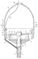
- figure 1 shows a longitudinal section of the embodiment of a pre unwinding device according to the invention
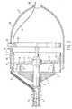
- figure 2 shows an improved embodiment of the device according to figure 1.
- FIG 1 is a central axis that is supported in a housing [2] by means of bearing [3]. This axis rotates in the direction of the arrow.
- Fixed to the housing [2] is a baseplate [4] supporting the stationairy winding body [5].
- the thread [7] is wound on the winding body [5].
- the fingers [8] and [9] are provided to move the windings in the direction of the axis. These fingers protrude through openings in the winding body [5].
- These fingers are connected to a driver [10] provided with a bearing [11] that is positioned excentrically in a known manner with respect to the central axis of the driving axis thereby forming a small angle.
- the fingers [8] and [9] are following an elliptical pattern having a component parallel to the central axis and a component radial to the axis.
- Such a construction of the driver is described eg in US-P-4 632 154 and Japanese patent 43 377/91.
- the winding body is constructed from an cylinder surface and its axis coincedances with the driving axis , and is divided in sectorshaped elements. These sectorshaped elements are adjustable radially whereby the diameter of the surrounding plane of these elements is increased or decreased. Different constructions for adjustment of the diameter of the winding body are possible.
- FIG 1 is a body of revolution with an almost cylindrical part [16] adjacent to the winding body [5] and an adjacent balloonshaped part [17] provided with an discharge device for the thread [18].
- [19] is a stopping body that blocks the thread (20) that is being drawn off from the winding body, at the right moment.
- This problem is solved according to the invention by moving the receiving cylinder [16] and the stopping body in a direction almost perpendicular to the axis of the winding body [5], like indicated by the arrow [21]. In this way the clearance in between the body [5] and the part [16] at the spot of the stopping device can be kept constant.
- the clearance in between the body [5] and the receiving cylinder [16] opposite the stopping body can increase or decrease, but this is no problem because no stopping body is present at that spot.
- stopping body [19] and receiving cylinder [16] are moved independently and it is preferred with respect to the simplicity of the construction and its adjustment, to connect the stopping body [19] and the receiving cylinder [16] with each other.
- Figure 2 shows a discshaped device [25] that is positioned almost perpendicular to the axis of the winding body and is connected heretoo.
- the stopping body [19] is activated in the space in between the receiving cylinder or the balloonshaped extension [17] and the disc [25]. This results in a more fluent course of the thread [20].
- Disc [25] can be connected to winding cylinder [16] and stopping device [19].
- Figure 2 indicates the parts in the same manner using the same numbers corresponding to the related parts of figure 1.
- the stopping body [19] is prefereably pinshaped and formed and positioned in such way that it corresponds to a clearance in the edge of disc [25] in the stopped position.
- Disc [25] is preferably moved together with the receiving cylinder [16] and the stopping body [19].
Landscapes
- Engineering & Computer Science (AREA)
- Textile Engineering (AREA)
- Looms (AREA)
- Forwarding And Storing Of Filamentary Material (AREA)
Description
Claims (7)
- A pre unwinding device according to the invention for use in a spoolless weaving loom, in particular using a weftinjector, comprising a central shaft [1] enclosed by a housing [2], whereby the thread [7] is taken from a supply coil [6], and by a relative rotation of the central shaft [1] and a winding body [5], is wound on that body [5] in adjacent eventually separated windings, whereby the winding body [5] shows an adjustable diameter in a plane perpendicular to the central shaft [1] and is situated within a surrounding receiving cylinder [16] for thread [7] leaving the winding body [5], provided with a stopping device [19] having such shape and position that at the moment that the thread discharge from the winding body [5] has to be ended, the stopping device [19] can be activated within the receiving cylinder [16], characterised in that the receiving cylinder [16] and the stopping device [19] are moveable in a plane almost perpendicular to the central axis [1] of the winding body [5].
- Pre unwinding device as claimed in claim 1, characterized in that the stopping device [19] and the receiving cylinder [16] are connected together.
- Pre unwinding device as claimed in claim 1 or 2, characterized in that a disc- or ringshaped device [25] is located downstream with respect to the winding body [5] within the receiving cylinder [16], almost perpendicular to the central axis [1] of the winding body [5], with a diameter smaller than the diameter of the receiving cylinder [16] and at least equalling the largest adjustable diameter of the winding body [5].
- Pre unwinding device as claimed in claim 3, characterized in that the disc or ringshaped device [25] is movable together with the receiving cylinder [16] and the stopping device [19].
- Pre unwinding device as claimed in claim 3 or 4, characterized in that the stopping device [19] can be activated in the space in between the receiving cylinder [16] and the disc- or ringshaped device [25], and closes this space locally.
- Pre unwinding device as claimed in claim 3, 4 or 5 characterized in that the stopping device [19] is pinshaped and corresponds to a clearance in the edge of the movable disc or ringshaped device [25] in the stopped position.
- Weaving loom provided with a pre unwinding device according to claim 1, 2, 3, 4, 5 or 6.
Applications Claiming Priority (3)
| Application Number | Priority Date | Filing Date | Title |
|---|---|---|---|
| NL9400726A NL9400726A (en) | 1994-05-03 | 1994-05-03 | Pre-unwinding device for use with a spoolless loom and loom provided with such a device. |
| NL9400726 | 1994-05-03 | ||
| PCT/NL1995/000154 WO1995030033A1 (en) | 1994-05-03 | 1995-04-28 | Pre unwinding device for use in a shuttleless weaving loom and weaving loom provided with such a device |
Publications (2)
| Publication Number | Publication Date |
|---|---|
| EP0774018A1 EP0774018A1 (en) | 1997-05-21 |
| EP0774018B1 true EP0774018B1 (en) | 1999-05-26 |
Family
ID=19864150
Family Applications (1)
| Application Number | Title | Priority Date | Filing Date |
|---|---|---|---|
| EP95916850A Expired - Lifetime EP0774018B1 (en) | 1994-05-03 | 1995-04-28 | Pre unwinding device for use in a shuttleless weaving loom and weaving loom provided with such a device |
Country Status (8)
| Country | Link |
|---|---|
| US (1) | US5725027A (en) |
| EP (1) | EP0774018B1 (en) |
| JP (1) | JPH09512589A (en) |
| CN (1) | CN1044628C (en) |
| AU (1) | AU2319795A (en) |
| DE (1) | DE69509902T2 (en) |
| NL (1) | NL9400726A (en) |
| WO (1) | WO1995030033A1 (en) |
Families Citing this family (3)
| Publication number | Priority date | Publication date | Assignee | Title |
|---|---|---|---|---|
| WO2001027370A1 (en) * | 1999-10-08 | 2001-04-19 | Memminger-Iro Gmbh | A thread accumulator-feeder for textile machines used for knitted goods, hosiery and similar |
| NL1020412C2 (en) * | 2002-04-17 | 2003-10-20 | Te Strake Textile B V | Method for adjusting the diameter of the winding body of a pre-winding device as well as such a pre-winding device. |
| CN102140724A (en) * | 2011-04-19 | 2011-08-03 | 许晓华 | Structural improvement of rotary shaft |
Family Cites Families (9)
| Publication number | Priority date | Publication date | Assignee | Title |
|---|---|---|---|---|
| CH569655A5 (en) * | 1973-09-25 | 1975-11-28 | Sulzer Ag | |
| DE3372297D1 (en) * | 1983-11-22 | 1987-08-06 | Rueti Ag Maschf | Weft yarn storage unit for looms |
| IT8422055U1 (en) * | 1984-06-04 | 1985-12-04 | Roy Electrotex Spa | WEFT FEEDER FOR WEAVING LOOM EQUIPPED WITH IMPROVED MEANS FOR ACCUMULATING THE WEFT RESERVE. |
| IT1204330B (en) * | 1986-04-30 | 1989-03-01 | Sarfati & Vischiani Spa | ACCUMULATOR DEVICE FOR WEFT WIRE FEEDERS IN TEXTILE MACHINES |
| DE8800216U1 (en) * | 1987-11-29 | 1989-03-30 | Aktiebolaget Iro, Ulricehamn | Device for storing, delivering and measuring a thread |
| IT1246421B (en) * | 1990-08-03 | 1994-11-18 | Roy Electrotex Spa | WEFT FEEDER FOR WEAVING FRAMES WITH ADJUSTABLE SECTION WINDING GROUP |
| DE4139583C2 (en) * | 1990-12-21 | 1994-02-17 | Ichikawa Iron Works Co | Weft feeders for weaving machines |
| NL9201436A (en) * | 1992-08-11 | 1994-03-01 | Te Strake Bv | Pre-unwinding device for use with a spoolless loom, in particular a loom operating with a weft thread injector. |
| IT1261256B (en) * | 1993-09-10 | 1996-05-09 | Lgl Electronics Spa | SEPARATION DEVICE OF YARN RESERVE COILS FOR WEFT FEEDERS AND WEAVING FRAMES AND SIMILAR |
-
1994
- 1994-05-03 NL NL9400726A patent/NL9400726A/en not_active Application Discontinuation
-
1995
- 1995-04-28 EP EP95916850A patent/EP0774018B1/en not_active Expired - Lifetime
- 1995-04-28 US US08/737,082 patent/US5725027A/en not_active Expired - Fee Related
- 1995-04-28 AU AU23197/95A patent/AU2319795A/en not_active Abandoned
- 1995-04-28 DE DE69509902T patent/DE69509902T2/en not_active Expired - Lifetime
- 1995-04-28 JP JP7522550A patent/JPH09512589A/en active Pending
- 1995-04-28 CN CN95192890A patent/CN1044628C/en not_active Expired - Lifetime
- 1995-04-28 WO PCT/NL1995/000154 patent/WO1995030033A1/en not_active Ceased
Also Published As
| Publication number | Publication date |
|---|---|
| JPH09512589A (en) | 1997-12-16 |
| EP0774018A1 (en) | 1997-05-21 |
| DE69509902T2 (en) | 1999-10-14 |
| DE69509902D1 (en) | 1999-07-01 |
| NL9400726A (en) | 1995-12-01 |
| US5725027A (en) | 1998-03-10 |
| CN1147279A (en) | 1997-04-09 |
| CN1044628C (en) | 1999-08-11 |
| WO1995030033A1 (en) | 1995-11-09 |
| AU2319795A (en) | 1995-11-29 |
Similar Documents
| Publication | Publication Date | Title |
|---|---|---|
| US4429723A (en) | Yarn braking means for yarn feeding devices | |
| EP0652312B1 (en) | Device for the positive modulated braking of thread for weft feeders | |
| EP0192851B1 (en) | Delivery device for yarns | |
| JP3476461B2 (en) | Weft feeder | |
| US4638840A (en) | Weft feeder for weaving looms | |
| JPS63160981A (en) | Adjustable yarn-adjusting bobbin | |
| EP0164033A2 (en) | Weft feeder for weaving looms | |
| HK791A (en) | Device for storing and delivering threads, especially for textile machines | |
| CN85108363A (en) | Yarn brake, in particular for textile machines | |
| US4766937A (en) | Weft storage device | |
| US5725027A (en) | Weft feeder | |
| US5046537A (en) | Weft yarn reserve winding unit with adjustable diameter winding drum | |
| EP0080692B1 (en) | Weft yarn storage unit for jet looms | |
| US4643369A (en) | Storage device for filamentary material | |
| EP0084032B1 (en) | Weft yarn metering device | |
| US4691742A (en) | Surplus warp yarn treating device of loom | |
| CN1270010C (en) | Balloon proof device for weft feeder of loom | |
| EP1354836A1 (en) | Method for adjusting the diameter of the winding body of a pre-unwinding device as well as such a pre-unwinding device | |
| EP1094138B1 (en) | Anti-balloon device for textile loom weft feeders | |
| US4623007A (en) | Device for metering weft yarn | |
| JPS62289650A (en) | Apparatus for measuring length of weft yarn and storing saidyarn | |
| SU1104211A1 (en) | Device for fastening filtering material | |
| DE2556373A1 (en) | Bobbin winder yarn monitor - has a braking action on yarn detector mechanism to lock it in place during bobbin changes and prevent false yarn breakage signals | |
| EP0159064A1 (en) | Wire-tensioning device for a coil-winding machine | |
| JPS60155756A (en) | Adjustment of length measuring amount in weft yarn length measuring apparatus of shuttleless loom |
Legal Events
| Date | Code | Title | Description |
|---|---|---|---|
| PUAI | Public reference made under article 153(3) epc to a published international application that has entered the european phase |
Free format text: ORIGINAL CODE: 0009012 |
|
| 17P | Request for examination filed |
Effective date: 19961010 |
|
| AK | Designated contracting states |
Kind code of ref document: A1 Designated state(s): DE FR IT |
|
| GRAG | Despatch of communication of intention to grant |
Free format text: ORIGINAL CODE: EPIDOS AGRA |
|
| GRAG | Despatch of communication of intention to grant |
Free format text: ORIGINAL CODE: EPIDOS AGRA |
|
| GRAH | Despatch of communication of intention to grant a patent |
Free format text: ORIGINAL CODE: EPIDOS IGRA |
|
| 17Q | First examination report despatched |
Effective date: 19981019 |
|
| GRAH | Despatch of communication of intention to grant a patent |
Free format text: ORIGINAL CODE: EPIDOS IGRA |
|
| GRAA | (expected) grant |
Free format text: ORIGINAL CODE: 0009210 |
|
| AK | Designated contracting states |
Kind code of ref document: B1 Designated state(s): DE FR IT |
|
| REF | Corresponds to: |
Ref document number: 69509902 Country of ref document: DE Date of ref document: 19990701 |
|
| ET | Fr: translation filed | ||
| PLBE | No opposition filed within time limit |
Free format text: ORIGINAL CODE: 0009261 |
|
| STAA | Information on the status of an ep patent application or granted ep patent |
Free format text: STATUS: NO OPPOSITION FILED WITHIN TIME LIMIT |
|
| 26N | No opposition filed | ||
| REG | Reference to a national code |
Ref country code: FR Ref legal event code: ST |
|
| REG | Reference to a national code |
Ref country code: FR Ref legal event code: RN |
|
| REG | Reference to a national code |
Ref country code: FR Ref legal event code: FC |
|
| REG | Reference to a national code |
Ref country code: FR Ref legal event code: TP |
|
| REG | Reference to a national code |
Ref country code: FR Ref legal event code: TP |
|
| PGFP | Annual fee paid to national office [announced via postgrant information from national office to epo] |
Ref country code: FR Payment date: 20080422 Year of fee payment: 14 |
|
| REG | Reference to a national code |
Ref country code: FR Ref legal event code: ST Effective date: 20100531 |
|
| PG25 | Lapsed in a contracting state [announced via postgrant information from national office to epo] |
Ref country code: FR Free format text: LAPSE BECAUSE OF NON-PAYMENT OF DUE FEES Effective date: 20090430 |
|
| PGFP | Annual fee paid to national office [announced via postgrant information from national office to epo] |
Ref country code: DE Payment date: 20110620 Year of fee payment: 17 |
|
| REG | Reference to a national code |
Ref country code: DE Ref legal event code: R119 Ref document number: 69509902 Country of ref document: DE Effective date: 20121101 |
|
| PGFP | Annual fee paid to national office [announced via postgrant information from national office to epo] |
Ref country code: IT Payment date: 20140424 Year of fee payment: 20 |
|
| PG25 | Lapsed in a contracting state [announced via postgrant information from national office to epo] |
Ref country code: DE Free format text: LAPSE BECAUSE OF NON-PAYMENT OF DUE FEES Effective date: 20121101 |