EP0773882B1 - Vacuum packaged escape slide - Google Patents
Vacuum packaged escape slide Download PDFInfo
- Publication number
- EP0773882B1 EP0773882B1 EP96924299A EP96924299A EP0773882B1 EP 0773882 B1 EP0773882 B1 EP 0773882B1 EP 96924299 A EP96924299 A EP 96924299A EP 96924299 A EP96924299 A EP 96924299A EP 0773882 B1 EP0773882 B1 EP 0773882B1
- Authority
- EP
- European Patent Office
- Prior art keywords
- envelope
- girt
- escape slide
- tear initiator
- attached
- Prior art date
- Legal status (The legal status is an assumption and is not a legal conclusion. Google has not performed a legal analysis and makes no representation as to the accuracy of the status listed.)
- Expired - Lifetime
Links
- 239000003999 initiator Substances 0.000 claims description 73
- 239000000463 material Substances 0.000 claims description 29
- 238000000034 method Methods 0.000 claims description 15
- 239000004677 Nylon Substances 0.000 claims description 6
- 229920001778 nylon Polymers 0.000 claims description 6
- 238000007789 sealing Methods 0.000 claims description 5
- 229910052782 aluminium Inorganic materials 0.000 claims description 4
- XAGFODPZIPBFFR-UHFFFAOYSA-N aluminium Chemical compound [Al] XAGFODPZIPBFFR-UHFFFAOYSA-N 0.000 claims description 4
- 239000011888 foil Substances 0.000 claims description 4
- 229920001684 low density polyethylene Polymers 0.000 claims description 4
- 239000004702 low-density polyethylene Substances 0.000 claims description 4
- 238000009461 vacuum packaging Methods 0.000 claims description 3
- CURLTUGMZLYLDI-UHFFFAOYSA-N Carbon dioxide Chemical compound O=C=O CURLTUGMZLYLDI-UHFFFAOYSA-N 0.000 claims 6
- 229910002092 carbon dioxide Inorganic materials 0.000 claims 3
- 239000001569 carbon dioxide Substances 0.000 claims 3
- 239000004698 Polyethylene Substances 0.000 claims 1
- -1 polyethylene Polymers 0.000 claims 1
- 229920000573 polyethylene Polymers 0.000 claims 1
- 239000007789 gas Substances 0.000 description 21
- 238000010586 diagram Methods 0.000 description 12
- 239000004744 fabric Substances 0.000 description 8
- 238000004806 packaging method and process Methods 0.000 description 4
- 238000007689 inspection Methods 0.000 description 3
- 229910052751 metal Inorganic materials 0.000 description 3
- 239000002184 metal Substances 0.000 description 3
- 230000001681 protective effect Effects 0.000 description 3
- 230000004083 survival effect Effects 0.000 description 3
- 241000233866 Fungi Species 0.000 description 2
- CBENFWSGALASAD-UHFFFAOYSA-N Ozone Chemical compound [O-][O+]=O CBENFWSGALASAD-UHFFFAOYSA-N 0.000 description 2
- 239000000853 adhesive Substances 0.000 description 2
- 230000001070 adhesive effect Effects 0.000 description 2
- 230000032683 aging Effects 0.000 description 2
- QVGXLLKOCUKJST-UHFFFAOYSA-N atomic oxygen Chemical compound [O] QVGXLLKOCUKJST-UHFFFAOYSA-N 0.000 description 2
- 239000000446 fuel Substances 0.000 description 2
- 230000005484 gravity Effects 0.000 description 2
- 230000000977 initiatory effect Effects 0.000 description 2
- 239000001301 oxygen Substances 0.000 description 2
- 229910052760 oxygen Inorganic materials 0.000 description 2
- 238000012856 packing Methods 0.000 description 2
- 239000004033 plastic Substances 0.000 description 2
- 229920003023 plastic Polymers 0.000 description 2
- 238000012857 repacking Methods 0.000 description 2
- 229910000831 Steel Inorganic materials 0.000 description 1
- 230000003466 anti-cipated effect Effects 0.000 description 1
- 239000003795 chemical substances by application Substances 0.000 description 1
- 230000006835 compression Effects 0.000 description 1
- 238000007906 compression Methods 0.000 description 1
- 230000001351 cycling effect Effects 0.000 description 1
- 230000006866 deterioration Effects 0.000 description 1
- 230000000694 effects Effects 0.000 description 1
- 230000005611 electricity Effects 0.000 description 1
- 229920003247 engineering thermoplastic Polymers 0.000 description 1
- 230000007613 environmental effect Effects 0.000 description 1
- 238000009434 installation Methods 0.000 description 1
- 238000012986 modification Methods 0.000 description 1
- 230000004048 modification Effects 0.000 description 1
- 229920001084 poly(chloroprene) Polymers 0.000 description 1
- 229920000728 polyester Polymers 0.000 description 1
- 238000003825 pressing Methods 0.000 description 1
- 230000001902 propagating effect Effects 0.000 description 1
- 239000010959 steel Substances 0.000 description 1
- 230000001960 triggered effect Effects 0.000 description 1
Images




Classifications
-
- A—HUMAN NECESSITIES
- A62—LIFE-SAVING; FIRE-FIGHTING
- A62B—DEVICES, APPARATUS OR METHODS FOR LIFE-SAVING
- A62B1/00—Devices for lowering persons from buildings or the like
- A62B1/20—Devices for lowering persons from buildings or the like by making use of sliding-ropes, sliding-poles or chutes, e.g. hoses, pipes, sliding-grooves, sliding-sheets
-
- B—PERFORMING OPERATIONS; TRANSPORTING
- B64—AIRCRAFT; AVIATION; COSMONAUTICS
- B64D—EQUIPMENT FOR FITTING IN OR TO AIRCRAFT; FLIGHT SUITS; PARACHUTES; ARRANGEMENT OR MOUNTING OF POWER PLANTS OR PROPULSION TRANSMISSIONS IN AIRCRAFT
- B64D25/00—Emergency apparatus or devices, not otherwise provided for
- B64D25/08—Ejecting or escaping means
- B64D25/14—Inflatable escape chutes
Definitions
- the present invention relates to inflatable escape slides and inflatable slide rafts for use by passengers evacuating aircraft.
- the slides are environmentally sealed under a vacuum to reduce the overall bulk of the stored slide and to extend the slide's repack interval and overall useful life.
- Inflatable escape slides are installed in virtually all large passenger-carrying aircraft to provide a rapid means for evacuating passengers in the event of an emergency.
- Such inflatable escape slides typically include at least one inflatable structural beam member.
- the slide surface (for use by the evacuating passengers) is provided on the upper side of the structural beam member.
- the structural beam member is inflated using compressed gas and an aspirator and/or a turbo fan.
- the upper end of the structural beam member is connected to the bottom of the aircraft's doorway by a girt bar assembly.
- Prior art inflatable escape slides are disclosed, for example, in U.S. Pat. Nos. 2,765,131, 3,102,623, and 3,860,984.
- the packed escape slide must be small enough to reliably deploy through the aircraft door when activated. Also, it must not interfere with the normal operation of the door, or with the use of the door by passengers exiting the aircraft.
- the packing procedure for inflatable escape slides is generally both time-consuming and labour-intensive. It may require as many as three or four persons.
- the escape slide is folded in a sequence which will allow reliable inflation and deployment.
- the folded escape slide is then placed into a relatively shallow receptacle commonly called a packboard.
- a series of fabric panels, which are attached to the periphery of the packboard, are then laced together with cord to contain the folded escape slide between the packboard and the fabric panels.
- the packed escape slide is then compressed to the desired configuration by manually pressing down the surfaces of the packed assembly and tightening the laces. Alternatively, a vacuum line is applied to the inflatable member(s) of the slide, and the packboard laces are tightened.
- the inflatable members of the escape slides might be damaged during both the preliminary folding operation and the subsequent compression of the slide.
- the inflatable members are generally fabricated from a neoprene rubber-coated fabric that may be punctured or torn by hard-surfaced apparatus such as lighting fixtures, survival equipment, inflation devices, or compressed gas reservoirs that are packaged with the escape slide.
- slide/raft packs can include radio beacons, locator lights and their associated batteries, antennae, hand pumps, anchors, heaving lines, knives, and canopies.
- inflatable escape slides have a limited useful service life of about 15 years. During this time, typical escape slides must be inspected at least three times. Inspection usually includes deploying the slide, inspecting it, and repacking it. The service life of a typical inflatable escape slide is affected by (1) the wear due to the inspection and repack cycle, (2) deterioration due to exposures to an atmosphere that may contain corrosive gases, e.g. , jet fuel, hydraulic fuel vapors, engine exhaust, and (3) aging of the escape slide materials due to fungus growth, moisture, oxygen, ozone, smog, ultraviolet light, high temperature/low temperature cycling, and aircraft vibration.
- corrosive gases e.g. , jet fuel, hydraulic fuel vapors, engine exhaust
- aging of the escape slide materials due to fungus growth, moisture, oxygen, ozone, smog, ultraviolet light, high temperature/low temperature cycling, and aircraft vibration.
- an environmentally sealed escape slide system as claimed in claim 1, a method for deploying such a slide system as defined in claim 10, a method for vacuum packing an escape slide as defined in claim 15 and an envelope as defined in claim 20.
- An environmentally sealed escape slide system in accordance with the present invention seeks to provide an environmentally-sealed vacuum packaged envelope with unique automatic deployment of the inflatable escape slide.
- the present invention also seeks to provide means for mounting a gas cylinder, for inflating the escape slide in the event of an emergency, and a battery pack, for illuminating the inflated slide, outside the vacuum packaged envelope.
- the vacuum-packaged envelope is formed from pliable multilayer gas-impermeable materials. It has an upper piece and a lower piece that are heat-sealed together along their periphery.
- the envelope is also sealed to and around a girt interface flange contained inside the vacuum envelope.
- the girt interface flange is connected to the escape slide and is the means for attaching the escape slide to the aircraft.
- the vacuum envelope includes external attachment points for the tear initiator cords used to automatically rip open the vacuum envelope just prior to the inflation of the slide.
- the vacuum envelope also includes external attachment points for mounting the gas cylinder that is used to initiate the inflation of the slide, and a battery pack that is used to power the slide's lights.
- a CO 2 cylinder is connected to an aspirator contained within the vacuum envelope using a hose assembly with a special disconnect fitting.
- the hose fitting is equipped with a rupture disk. It is located at the vacuum envelope interface and enables easy connection and disconnection of the CO 2 cylinder from the sealed slide assembly.
- the envelope material is sealed around the hose fitting to maintain the vacuum.
- the battery pack for powering the slide lights is mounted external to the vacuum envelope.
- the slide lights are sealed within the vacuum envelope.
- the battery pack and the slide lights are connected via a vacuum-tight feed-through at the interface to the vacuum envelope. This feedthrough enables the connection and disconnection of the battery pack from the sealed slide assembly.
- the envelope is sealed around the feedthrough to maintain the vacuum seal.
- the CO 2 cylinder and the battery pack can be changed without compromising the vacuum packaged envelope. This eliminates the need to repack the slide whenever either the battery pack or the CO 2 cylinder is inspected or replaced.
- the packaging procedure includes: (1) placing the folded escape slide in the vacuum envelope; (2) sealing the vacuum envelope around the girt interface flange, the hose fitting, and the electrical fitting; (3) compressing the inflatable escape slide, and evacuating the escape slide with a vacuum line; (4) disconnecting the vacuum line from the inflatable slide; (5) evacuating the envelope; and (6) sealing the vacuum envelope at its periphery.
- the battery pack and the CO 2 cylinder are connected to the vacuum envelope.
- the girt interface flange of the vacuum envelope is also connected to a length of girt material which is used to attach the vacuum envelope to the aircraft.
- the vacuum packaged escape slide In the undeployed or stowed position, the vacuum packaged escape slide is mounted to the interior of the aircraft door or some area immediately adjacent thereto. Automatic deployment of the vacuum packaged evacuation slide system is accomplished by attaching the tear initiation cords to the girt assembly that is attached to the aircraft. Prior to flight, the escape slide is armed by attaching the free end of the girt to the bottom of the aircraft doorway, using the girt bar. In this armed configuration, a considerable amount of slack exists in both the girt and the tear initiator cords. The overall length of the tear initiator cords is selected such that they become fully taut just before the girt is fully taut.
- the slack is pulled from the tear initiator cords and the girt.
- the tear initiator cords are fully taut, they rip open the vacuum envelope.
- the girt becomes fully taut, so that the girt bar pulls the folded slide assembly from the storage position.
- the folded slide assembly then falls under the influence of gravity between the open door and the sill. Subsequently, the slide is inflated rapidly and is ready for the evacuation of passengers within seconds of the door opening.
- Tear initiation of the vacuum envelope is ensured by forming a seal area on a crease on the envelope near each of the tear initiator cord attachment points, and then cutting partway into the seal area to ensure a low tear-initiation force.
- the material selected for the envelope must be "notch-sensitive," i.e., the force required to propagate a tear in the material must be much lower than the force required to initiate the tear.
- a tear is initiated in the general area of the aspirator intake. To ensure that the envelope does not block airflow into the aspirator, or that material is not sucked inside the mouth the aspirator during inflation, the vacuum envelope material over this area is pulled away as part of the tearing scheme.
- the present invention seeks to increase the inspection/repack cycle of inflatable escape slides from the present cycle of approximately 5 years to 15 years or longer, by vacuum-packaging the escape slide to reduce the aging of the escape slide.
- the packaging system protects the escape slide from harmful environmental agents such as moisture, ultraviolet light, smog, oxygen, ozone, mildew, and fungus. It is anticipated that the service life of escape slides can be extended from the current 15-year period to 25 years or more.
- the present invention also seeks to provide an inflatable escape slide that does not require repacking when either the gas cylinder or the battery pack is inspected or replaced.
- the present invention also seeks to reduce the overall dimensions of stowed inflatable escape slides.
- the present invention also seeks to reduce the labour required to pack inflatable escape slides.
- Figures 1a and 1b show the escape slide as it is installed on the interior surface of an aircraft door 34.
- Figure 1a shows the escape slide without its protective covering
- Figure 1b shows the escape slide stowed within protective covering 35.
- Tear initiator cords 42, 47 and 58 are attached to vacuum envelope 1 and to girt bar 37, such that when the door is opened (by swinging it horizontally out from hinges 71), the tear initiator cords rip open vacuum envelope 1 and initiate deployment of the escape slide.
- Figure 1a also shows CO 2 gas cylinder 7 and battery pack 52 which are mounted outside the vacuum envelope, and outer girt 36, which attaches the escape slide to girt bar 37, and thus to the bottom of the doorway.
- the escape slide Prior to each take-off, the escape slide is armed for deployment by attaching outer girt 36 and tear initiator cords 42 and 47 to the bottom of the aircraft doorway, via girt bar 37.
- Vacuum envelope 1 is fabricated from pliable multi-layer gas-impermeable materials such as layers of polyester or nylon, aluminum foil, and low-density polyethylene.
- the preferred materials include layers of nylon, aluminum foil and low-density polyethylene.
- Vacuum envelope 1 could be made from of an upper piece and a lower piece, which are heat-sealed together along the periphery to form an environmentally sealed container, or it could be made from a single piece folded back on itself and sealed.
- FIG 1 a shows CO 2 gas cylinder 7 connected to the sealed slide assembly as it would be installed under protective bustle 35.
- CO 2 gas cylinder 7 is attached to slide 5 by two straps 15 that pass around cylinder 7 and through the eye of each vacuum envelope attachment point 6.
- Cylinder 7 may or may not be contained within a fabric pouch (not shown).
- the CO 2 gas in cylinder 7 is released when the door is opened in an emergency.
- the valve of cylinder 7 is held closed by a pin connected by a cable to girt bar 37.
- the cable is also connected to a fabric handle, to allow for manual inflation of the slide, if necessary.
- the girt bar pulls the entire slide assembly out from under the bustle 35. As the assembly falls, the pin is pulled out from the cylinder, after all slack is taken up from the cable attaching the pin to girt bar 37.
- the CO 2 gas from cylinder 7 flows into the slide 5 through hose 39.
- Hose 39 is connected to an aspirator 49 (described below in connection with Figure 9c) that facilitates the inflation of slide 5.
- Feedthrough 8 described in detail in connection with Figures 6a-6b, is mounted in the wall of vacuum envelope 1. It allows hose 39 to pass through the wall of the vacuum envelope 1. Feedthrough 8 also provides a means for disconnecting hose 39 at the vacuum envelope interface, so that cylinder 7 can be replaced.
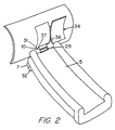
- Figure 2 shows inflatable escape slide 5 in its deployed position with the CO 2 cylinder 7 attached to the underside of escape slide 5.
- the top end of escape slide 5 is attached to girt bar 37, at the bottom of the airplane doorway, by outer girt 36.
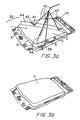
- Figures 3a and 3b are top and bottom views, respectively, of a folded inflatable escape slide 5 in a vacuum envelope 1.
- the vacuum envelope 1 is sealed to and around girt interface flange 10, hose feedthrough 8, and electrical feedthrough 9.
- the escape slide 5 is evacuated first, and then vacuum envelope 1 is evacuated and sealed, forming sealed escape slide assembly 33.
- Vacuum envelope 1 includes several features which allow the slide assembly contained within vacuum envelope 1 to interface with the external environment without compromising the vacuum environment inside vacuum envelope 1. These features are best seen in Figure 3a. They include two gas cylinder attachment points 6, sealed hose feedthrough 8, sealed electrical feedthrough 9, and girt interface flange 10.
- Figures 3a and 3b show that the upper side 3 and the lower side 4 of vacuum envelope 1 also include four attachment points 41 for the upper and lower tear initiator cords 42 and 47, respectively, that are used to rip open the vacuum envelope 1.
- the attachment points 41 are located on flaps 44 that have been formed in the upper side 3 of vacuum envelope 1, by folding and sealing the envelope material onto itself. Similar tear initiators may be formed on the back side of the envelope, if required.
- Figure 3a also shows tear initiators 43 in flaps 44.
- Tear initiator cord 58 is attached to the envelope close to the mouth of aspirator 49, as explained in more detail below with reference to Figures 4a and 9c.
- one end of the tear initiator cords 42 and 47 is attached (along with the outer girt 36) to girt bar 37.
- a considerable amount of slack exists in both the outer girt 36 and tear initiator cords 42 and 47.
- the overall length of the tear initiator cords is selected such that the tear initiator cords become fully taut just before the outer girt is fully taut.
- FIGs 4a and 4b show tear initiator attachment point 41 in detail. These Figures show the tear initiator point that is closest to the mouth of aspirator 49.
- Figure 4b shows a cross-sectional view of attachment point 41, taken across the A-A line of Figure 4a. Tear initiator cord 46 loops through circular seal 60 in the vacuum envelope 1. Circular seal 60 may be reinforced with tape and/or a metal grommet 45.
- a tear initiator 43 is next to each attachment point 41. Tear initiators 43 are notches formed by cutting partway into the sealed and folded area of flap 44. Tears in the vacuum envelope 1 will propagate readily from these notches because the vacuum envelope material is notch-sensitive.
- Cord 46 shown in Figures 4a and 4b, is a tear-away cord that is only used with the one attachment point that is closest to the mouth of the aspirator 49. Tear-away cord 46 connects to tear initiator cord 58 for the purpose of tearing the envelope material away from the mouth of aspirator 49 when the vacuum envelope 1 is torn open. As shown in Figure 4a (see also Figure 9c below), cord 46 loops through the loop of the tear initiator cord 42. The other end of the cord 46 is attached to rigid disk 48 that has been placed inside vacuum envelope 1, directly over the mouth of aspirator 49.
- tear initiator points are similar to the tear initiator point shown in Figures 4a and 4b, except that they do not include cord 46, and have cord 42 as the tear initiator cord, instead of cord 58.
- the rigid disk is manufactured with a small lip, such that the lip slips around the mouth of aspirator 49.
- the lip helps keep rigid disk 48 in position over aspirator 49, but does not interfere with the removal of rigid disk 48 during deployment.
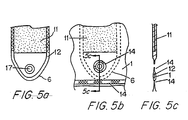
- Figures 5a-5c show gas cylinder attachment point 6 in detail.
- Figure 5a shows cylinder attachment point 6 before it has been sealed within vacuum envelope 1.
- Figures 5b and 5c show cylinder attachment point 6 after it has been sealed inside vacuum envelope 1.
- Figure 5c shows a cross-section of the internal cylinder attachment point 6, taken across the A-A line of Figure 5b.
- Attachment points 6 enable CO 2 cylinder 7, that is mounted outside sealed vacuum envelope 1, to be secured to the underside of the inflatable slide 5.
- CO 2 gas cylinder 7 is attached to the slide 5 via connectors 11 which are attached to the slide 5.
- Connectors 11 are preferably made from fabric that has webbing material 12 sewn along the edges. Excess webbing is left at the end of the fabric to form a loop.
- the internal cylinder attachment points 6 are connected to external cylinder attachments by creating a round heat seal in vacuum envelope 1 through the open loop of webbing.
- the hole through the envelope material can be reinforced to prevent tearing.
- the outer cylinder can then be mechanically attached through these holes.
- Cross-hatched shading in Figures 5a and 5b indicates heat seal areas 14.
- the vacuum envelope material covering each eye 17 is then punched out.
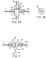
- FIG 6a shows hose feedthrough 8 in detail.
- Hose feedthrough 8 passes through a hole in the upper side of vacuum envelope 1. It is secured in place by a locking nut 18 which clamps the vacuum envelope material between metal flange 19 and locking nut 18.
- a gasket 20 seals the vacuum envelope 1 around the hose feedthrough 8. The gasket may be attached to the vacuum envelope with adhesive.
- the hose feedthrough 8 includes a rupture disk 21 that is shown in detail in Figure 6b. Rupture disk 21 is held in place over the orifice of hose feedthrough 8 by rupture disk insert 22. Rupture disk 21 provides an airtight seal within hose 39, thus enabling CO 2 cylinder 7 to be changed without compromising the vacuum environment of vacuumenvelope 1. When the gas cylinder 7 is triggered in an emergency, the pressure of the discharged CO 2 gas bursts the rupture disk 21, and the gas flows into the escape slide 5 through the hose 39.
- Inflatable escape slide 5 is equipped with lights (not shown) to aid in night-time evacuations. Electricity for the lights is provided by battery pack 52 that is connected to the lights by electrical wire 26. Battery pack 52 is mounted next to CO 2 cylinder 7 near the underside of escape slide 5, as can be seen in Figure 2. When escape slide 5 is stowed, battery pack 52 is mounted outside vacuum envelope 1 proximate to the CO 2 cylinder 7, while the slide lights are sealed within the vacuum envelope 1. Electrical feedthrough 9, mounted in the wall of vacuum envelope 1, allows wire 26 to pass through the wall of vacuum envelope 1. Electrical feedthrough 9 additionally provides a means for disconnecting battery pack 52 at the vacuum envelope interface.
- FIG. 7 shows electrical feedthrough 9 in detail. Electrical feedthrough 9 passes through a hole in the side of the vacuum envelope 1. It is secured by locking nut 24 which clamps the vacuum envelope material 1 between flange 23 and locking nut 24. Vacuum envelope 1 is additionally adhesively sealed around the electrical feedthrough 9. Shading 53 in Figure 7 indicates the adhesive seal area. Electrical feedthrough 9 includes a blind hole receptacle 25 for connecting and disconnecting battery pack 52. The electrical connector 28 of the battery pack 52 plugs into the blind hole receptacle 25. Wire 26, which connects directly to the slide lights, is soldered or crimped onto the prongs 54 of the electrical feedthrough 9. The electrical feedthrough 9 is preferably made of an engineering thermoplastic.
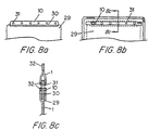
- FIGs 8a-d show girt interface flange 10 in detail.
- Girt interface flange 10 provides a means for attaching the sealed escape slide to the aircraft doorway.
- Figure 8a shows flange 10 as it appears before it is sealed within vacuum envelope 1.
- Figures 8b and 8c show girt interface flange 10 after it is sealed within vacuum envelope 1.
- Girt interface flange 10 is attached to one end of an inner girt 29 by heavy-duty stitching 30. The other end of inner girt 29 is attached to the top of the inflatable slide 5, as shown in Figure 2.
- Girt interface flange 10 is made of plastic, preferably one-eighth inch thick.
- Figures 8b and 8c show girt interface flange 10 after it has been sealed within vacuum envelope 1.
- the upper and lower pieces of the vacuum envelope 1 are heat-sealed together slightly beyond the outside edge of girt interface flange 10 and inner girt 29.
- the envelope material is also heat-sealed to the girt interface flange 10 in the area over and proximate to the eyelets 31.
- Shading 32 in Figures 8b and 8c indicates the seal area.
- the vacuum envelope material covering the eyelets 31 is then punched out. Eyelets 31 may be reinforced with metal grommets (not shown).
- FIG 8d is a more detailed diagram of the girt attachment between the slide and the aircraft.
- Outer girt 36 connects to the eyelets 31 of the girt interface flange 10 preferably using a series of loops 62 formed from nylon webbing. These loops are then passed through both the eyelets 31 and the corresponding holes in the outer girt 36. The loops are then mechanically locked with one or more steel pins 61. These pins are attached to a cable and terminated with a handle that, when pulled, unlocks the nylon loops and disconnects the slide from the aircraft. Preferably this connection can also be used as a release mechanism that disconnects the fully inflated slide from the evacuated aircraft.
- Figures 9a and 9b show disk 48 in detail.
- Figure 9c shows rigid disk 48 inside the upper piece of the vacuum envelope 1, positioned below flap 44 and above the aspirator 49.
- Cord 58 is connected to the disk 48 by looping through an eye 50.
- Disk 48 is preferably made of plastic.
- the aircraft door 34 swings horizontally outward. As the door opens, the slack is pulled from the tear initiator cords 42 and 47, and from the outer girt 36. When the tear initiator cords 42, 47, and 58 are fully taut, a force is transmitted from the girt bar 37, down the legs of the tear initiator cords 42 and 47 to the attachment points 41. The transmitted force then rips open vacuum envelope 1, propagating tears from the tear initiators 43. The tearing force is then transmitted along the cord 46 to the disk 48, which then causes the disk 48 and the surrounding envelope material to be torn away from the proximity of the mouth of the aspirator 49.
- Outer girt 36 then becomes fully taut, causing the folded slide assembly to pull away from aircraft door 34. Escape slide assembly then falls under the influence of gravity between the open door 34 and the door sill 51. Subsequently, escape slide 5 is inflated rapidly and is ready for evacuating passengers within a few seconds (typically 4 seconds) after the opening of door 34.
- the preferred embodiment described herein uses a vacuum envelope 1 having four attachment points 41, four tear initiators 43, and two envelope tear initiator cords 42 and 47.
- other embodiments could have more or fewer attachment points 41 and tear initiators 43, and more or fewer tear initiator cords.
Landscapes
- Business, Economics & Management (AREA)
- Emergency Management (AREA)
- Engineering & Computer Science (AREA)
- Aviation & Aerospace Engineering (AREA)
- Health & Medical Sciences (AREA)
- General Health & Medical Sciences (AREA)
- Packages (AREA)
- Vacuum Packaging (AREA)
- Tents Or Canopies (AREA)
Description
Claims (38)
- An environmentally sealed inflatable escape slide system comprising:(a) a vacuum packaged envelope (1) containing an inflatable escape slide (5), an aspirator (49) and at least one slide light;(b) means for connecting a gas cylinder (7) and a battery pack (52) to the inflatable escape slide (5) through the vacuum packaged envelope (1),
wherein said gas cylinder (7) and said battery pack (52) are external to the vacuum packaged envelope (1); said connecting means comprising(c) a sealed hose feedthrough (8) in the vacuum packaged envelope (1) comprising means for fluidly connecting a hose (39) from the gas cylinder (7) to the aspirator (49);(d) a sealed electrical feedthrough (9) in the vacuum envelope (1) comprising means for electrically connecting a wire (26) from a battery pack (52) to the at least one slide light; the environmentally sealed inflatable escape slide system further comprising(e) a tear initiator cord (43, 47) attached at one end to a tear initiator attachment point (41) on the vacuum packaged envelope (1), said tear initiator attachment point (41) proximate to a tear initiator point (43), and attached at the other end to a girt bar (37);(f) an inner girt (29) attached at one end to the inflatable escape slide (5), and attached at the other end to a girt interface flange (10), said inner girt (29) and said girt interface flange (10) inside the vacuum packaged envelope (1); and(g) an outer girt (36) attached at one end to the girt bar (37), and attached at the other end to the girt interface flange (10) through the vacuum packaged envelope (1). - The environmentally sealed inflatable escape slide system of claim 1, wherein the length of the tear initiator cord (42, 47) is such that, when the escape slide (5) is being deployed, the tear initiator cord (42, 47) becomes fully taut before the outer girt (36) is fully taut.
- The environmentally sealed inflatable escape slide system of claim 1, further comprising a battery pack (52) externally attached to the inflatable escape slide (5), said battery pack (52) comprising a wire (26) electrically connected to the sealed electrical feedthrough (9).
- The environmentally sealed inflatable escape slide system of claim 1, further comprising a gas cylinder (7) externally attached to the inflatable escape slide (5), said gas cylinder (7) comprising a hose (39) fluidly connected to the sealed hose feedthrough (8).
- The environmentally sealed inflatable escape slide system of claim 1, wherein the vacuum packaged envelope (1) comprises at least one flap (44), said flap (44) comprising at least one tear initiator attachment point (41) and at least one tear initiator point (43).
- The environmentally sealed inflatable escape slide system of claim 1, wherein the aspirator (49) has a mouth, and wherein a rigid disk (48) is positioned inside the vacuum packaged envelope (1) directly over the mouth of the aspirator (49).
- The inflatable escape slide system of claim 8, further comprising a tear away cord (46) attached at one end to the tear initiator attachment point (41) and to the tear initiator cord (42, 47), and attached at the other end to the rigid disk (48), wherein the tear initiator point (43) is close to the mouth of the aspirator (49).
- The environmentally sealed inflatable escape slide system of claim 1, wherein the vacuum packaged envelope (1) is fabricated from notch-sensitive material.
- An environmentally sealed inflatable escape slide system as claimed in any preceding claim, further comprising:(a) a carbon dioxide cylinder (7); and(b) a hose fluidly connecting (39) the carbon dioxide cylinder (7) to the aspirator (49).
- A method for deploying an escape slide (5), that is packed in a vacuum packaged envelope (1) mounted on an interior surface of an aircraft door (34) in an aircraft doorway, from the aircraft doorway comprising:(a) providing a gas cylinder (7) fluidly connected to the escape slide (5) through a sealed hose feedthrough (8) in the vacuum packaged envelope (1), an inner girt (29) attached at one end to the escape slide (5) and attached at the other end to a girt interface flange (10), said inner girt (29) and said girt interface flange (10) inside the vacuum packaged envelope (1), an outer girt (36) attached at one end to the girt interface flange (10) and attached at the other end to a girt bar (37), and tear initiator cords (42,47) attached at one end to the vacuum packaged envelope (1) and at the other end to the girt bar (37);(b) securing the girt bar (37) to a door sill of the aircraft doorway;(c) triggering the deployment of the escape slide (5) by opening the aircraft door (34);(d) the step of opening the aircraft door (34) further pulling the tear initiator cords (42,47) taut, such that they rip open the vacuum packaged envelope (1);(e) allowing the vacuum packaged envelope to fall out of the aircraft doorway, pulling the outer girt (36) taut;(f) the outer girt (36) pulling the escape slide (5) out of the vacuum packaged envelope (1); and(g) inflating the escape slide (5) using the gas cylinder (7).
- The method of claim 10 wherein the gas cylinder (7) is fluidly connected to the escape slide (5) through an aspirator (49).
- The method of claim 11 wherein the vacuum packaged envelope (1) comprises a rigid disk (48) inside the vacuum packaged envelope (1) positioned directly above the aspirator (49).
- The method of claim 12 wherein the rigid disk (48), and the portion of the vacuum packaged envelope (1) is torn away from the aspirator (49) when the tear initiator cord (42,47) becomes taut.
- The method of claim 10 wherein the escape slide (5) comprises lights, and wherein the lights are turned on as the escape slide (5) is deployed.
- A method for vacuum packing an escape slide (5) for an aircraft comprising:(a) providing an envelope (1) having at least one flap (44), said flap (44) comprising at least one tear initiator attachment point (41) and at least one tear initiator point (43), said envelope (1) also comprising a sealed hose feedthrough (8) and a sealed electrical feedthrough (9);(b) placing a folded escape slide in the envelope (1), said folded escape slide (5) comprising an inner girt (29) attached at one end to the folded escape slide (5) and attached at the other end to a girt interface flange (10);(c) placing an aspirator (49) fluidly connected to the folded escape slide (5) in the envelope (1);(d) sealing the envelope (1) around the folded escape slide (5), the girt interface flange (10), the sealed hose feedthrough (8) and the sealed electrical feedthrough (9);(e) evacuating the escape slide (5); and(f) sealing the envelope (1).
- The method of claim 15 further comprising attaching at least one tear initiator cord (42, 47) to at least one tear initiator attachment point (41).
- The method of claim 16 further comprising attaching one end of a tear-away cord (46) to the tear initiator cord (42, 47) and attaching the other end of the tear away cord (46) to a rigid disk (48) inside the envelope (1), wherein the rigid disk (48) covers a mouth of the aspirator (49).
- The method of claim 15 wherein the girt interface flange (10) is attached to a girt bar (37) by an outer girt (36).
- The method of claim 18 further comprising attaching the tear initiator cords (42, 47) To the girt bar (37).
- An envelope (1) fabricated from gas-impermeable, notch-sensitive materials comprising:(a) at least one flap (44), said flap (44) comprising a tear initiator point (43) and a tear initiator attachment point (41);(b) a sealed hose feedthrough (8) comprising a rupture disk (21);(c) a sealed electrical feedthrough (9);(d) a rigid disk positioned inside the envelope (1), just below a tear initiator attachment point (41);(e) an aspirator positioned in the envelope (1) below the rigid disk (48), said aspirator (49) fluidly connected to the sealed hose feedthrough (8); and(f) an escape slide (5) positioned inside the envelope (1), said escape slide (5) fluidly connected to the aspirator (49).
- The envelope of claim 20 wherein the notch-sensitive materials are multi-layer notch-sensitive materials.
- The envelope (1) of claim 21 wherein the multi-layer notch-sensitive materials comprise at least one material selected from nylon, aluminum foil and low density polyethylene.
- The envelope (1) of claim 21 wherein the multi-layer notch-sensitive materials comprise a layer of polyethylene.
- The envelope (1) of claim 21 wherein the multi-layer notch-sensitive materials comprise a layer of nylon, a layer of aluminum foil, and a layer of low density polyethylene.
- The envelope (1) of claim 20 further comprising two gas cylinder attachment points.
- The envelope (1) of claim 20 further comprising a girt bar (37) attached to the girt interface by an outer girt (36).
- The envelope (1) of claim 26 further comprising at least one tear initiator cord (42, 47) attached at one end to a tear initiator attachment point (41) and at the other end to the girt bar (37).
- The envelope (1) of claim 27 further comprising a tear-away cord (46) attached to the tear initiator attachment point (41) just above the rigid disk (48).
- The envelope (1) of claim 27 wherein the length of the at least one tear initiator cord (42, 47) is selected such that, when the envelope (1) is pulled away from the girt bar (37), the at least one tear initiator cord (42, 47) becomes taut before the outer girt (36) becomes taut.
- The environmentally sealed inflatable escape slide system of claim 1, further comprising a plurality of tear initiator cords (42, 47) and a plurality of corresponding tear initiator points (43), wherein each of said plurality of tear initiator cords (42, 47) is attached at one end proximate to a corresponding tear initiator point (43), and attached at the other end to the girt bar (37).
- The environmentally sealed inflatable escape slide system of claim 30, wherein the plurality of tear initiator cords (42, 47) are attached to the girt bar (37) by a single common portion of the plurality of tear initiator cords (42, 47).
- The environmentally sealed inflatable escape slide system of claim 30, wherein the length of the plurality of tear initiator cords (42, 47) are such that, when the escape side (5) is being deployed, the plurality of tear initiator cords (42, 47) become fully taut before the outer girt (36) is fully taut.
- The environmentally sealed inflatable escape slide system of claim 4, wherein the gas cylinder (7) is a carbon dioxide cylinder (7).
- The environmentally sealed inflatable escape slide system of claim 1, wherein the rigid disk (48) comprises a lip fitting around the mouth of the aspirator (49).
- The environmentally sealed inflatable escape slide system of claim 1, wherein the sealed hose feedthrough (8) comprises a rupture disk (21).
- The environmentally sealed inflatable escape slide system of claim 1, wherein the girt interface flange (10) comprises a plurality of eyelets (31).
- The environmentally sealed inflatable escape slide of claim 36, further comprising a plurality of loops and a plurality of pins (61), wherein said plurality of loops secure the outer girt (36) to the girt interface flange (10) via the plurality of eyelets (31) and wherein said plurality of pins (61) lock the plurality of loops in place.
- The environmentally sealed inflatable escape slide system of claim 37, further comprising a handle attached to the plurality of pins (61), wherein the handle is pulled, the plurality of pins (61) are removed from the plurality of loops thereby releasing the inflatable escape slide (5) from the outer girt (36).
Applications Claiming Priority (3)
| Application Number | Priority Date | Filing Date | Title |
|---|---|---|---|
| US477402 | 1995-06-07 | ||
| US08/477,402 US5586615A (en) | 1995-06-07 | 1995-06-07 | Vacuum packaged escape slide |
| PCT/US1996/010888 WO1996040556A1 (en) | 1995-06-07 | 1996-06-07 | Vacuum packaged escape slide |
Publications (3)
| Publication Number | Publication Date |
|---|---|
| EP0773882A1 EP0773882A1 (en) | 1997-05-21 |
| EP0773882A4 EP0773882A4 (en) | 1998-05-13 |
| EP0773882B1 true EP0773882B1 (en) | 2002-09-11 |
Family
ID=23895776
Family Applications (1)
| Application Number | Title | Priority Date | Filing Date |
|---|---|---|---|
| EP96924299A Expired - Lifetime EP0773882B1 (en) | 1995-06-07 | 1996-06-07 | Vacuum packaged escape slide |
Country Status (5)
| Country | Link |
|---|---|
| US (1) | US5586615A (en) |
| EP (1) | EP0773882B1 (en) |
| JP (1) | JP3101325B2 (en) |
| DE (1) | DE69623566T2 (en) |
| WO (1) | WO1996040556A1 (en) |
Families Citing this family (35)
| Publication number | Priority date | Publication date | Assignee | Title |
|---|---|---|---|---|
| US5988438A (en) * | 1998-03-16 | 1999-11-23 | Universal Propulsion Company, Inc. | Apparatus for rapid inflation of inflatable object and related method |
| FR2807388B1 (en) | 2000-04-07 | 2002-06-28 | Aerospatiale Matra Airbus | AIRCRAFT DOOR AND AIRCRAFT EQUIPPED WITH SUCH A DOOR |
| US7018079B1 (en) * | 2001-07-23 | 2006-03-28 | Dme Corporation | Aircraft escape slide lighting system |
| US6644596B1 (en) * | 2001-12-21 | 2003-11-11 | Air Cruisers Company | Deployment system for inflatable structures |
| US6641445B1 (en) | 2002-02-15 | 2003-11-04 | Air Cruisers Company | Deployment arrangement for inflatable structures |
| US6769647B2 (en) * | 2002-04-18 | 2004-08-03 | Goodrich Corporation | Automatic inflation system for evacuation slide |
| US6966414B2 (en) * | 2003-12-02 | 2005-11-22 | Goodrich Corporation | Elevated inflatable emergency evacuation slide illumination |
| DK176388B1 (en) * | 2004-07-21 | 2007-10-29 | Resq As | Packaging for the packaging of safety and rescue equipment and the use of the packaging therefor |
| US7434600B1 (en) | 2004-12-02 | 2008-10-14 | Air Cruisers Company | Pressurized actuator system for inflatable structures |
| US7644739B1 (en) | 2004-12-02 | 2010-01-12 | Air Cruisers Company | Pressurized actuation system for inflatable structures |
| US7380755B2 (en) * | 2005-05-26 | 2008-06-03 | Goodrich Corporation | Frangible pneumatic latch |
| EP1989108B1 (en) * | 2006-02-24 | 2015-07-01 | Apical Industries, Inc. | Door pod assembly |
| US7658417B2 (en) | 2006-02-24 | 2010-02-09 | Apical Industries, Inc. | Hose hinge assembly |
| US9457911B2 (en) * | 2013-02-11 | 2016-10-04 | Air Cruisers Company | Emergency evacuation systems door restraint lanyard for aircraft |
| US12049324B2 (en) * | 2013-03-15 | 2024-07-30 | United Airlines, Inc. | Aircraft emergency escape slide container and method of changing an aircraft emergency escape slide |
| KR101616822B1 (en) * | 2014-10-28 | 2016-04-29 | 삼성중공업 주식회사 | Deck house |
| KR101675371B1 (en) * | 2014-12-23 | 2016-11-11 | 한국철도기술연구원 | Double deck railway vehicle including emergency escape device for passengers on the second floor |
| US10160551B2 (en) * | 2015-08-18 | 2018-12-25 | Goodrich Corporation | Translucent illuminated evacuation slide |
| US10112063B1 (en) * | 2015-11-13 | 2018-10-30 | Altevac, Llc | Emergency escape slide incorporated into exit |
| US10318903B2 (en) | 2016-05-06 | 2019-06-11 | General Electric Company | Constrained cash computing system to optimally schedule aircraft repair capacity with closed loop dynamic physical state and asset utilization attainment control |
| US10124759B2 (en) | 2016-09-20 | 2018-11-13 | Autoliv Asp, Inc. | Aspirating airbag assemblies |
| CN206528646U (en) * | 2017-02-24 | 2017-09-29 | 深圳市大疆创新科技有限公司 | Battery compartment and unmanned vehicle |
| US10399302B2 (en) | 2017-05-18 | 2019-09-03 | Goodrich Aerospace Services Private Limited | Packaging film life raft enclosure |
| US10988104B2 (en) | 2017-11-01 | 2021-04-27 | Autoliv Asp, Inc. | Airbag aspiration modules and related valve assemblies |
| US10787269B2 (en) * | 2018-01-04 | 2020-09-29 | Goodrich Corporation | Automatic retracting firing cable |
| EP3787430B1 (en) | 2018-05-04 | 2022-12-14 | NIKE Innovate C.V. | Vacuum pouch for athletics |
| US11447257B2 (en) * | 2018-07-06 | 2022-09-20 | Goodrich Corporation | Systems and methods for soft cover attachment |
| US10913423B2 (en) | 2018-09-28 | 2021-02-09 | Autoliv Asp, Inc. | Aspirating airbag module assemblies and components |
| DE102018007688B4 (en) * | 2018-09-28 | 2020-07-30 | Airbus Operations Gmbh | Airplane door with an evacuation staircase |
| US10807736B2 (en) * | 2019-02-19 | 2020-10-20 | Goodrich Corporation | Wireless lighting system for aircraft evacuation systems |
| EP4108565B1 (en) * | 2021-06-25 | 2023-09-27 | Airbus Operations GmbH | Aircraft cabin section and aircraft having an aircraft cabin section |
| US11794685B2 (en) | 2021-11-01 | 2023-10-24 | Autoliv Asp, Inc. | Systems and methods for improved airbag aspiration |
| US12344183B2 (en) | 2021-11-01 | 2025-07-01 | Autoliv Asp, Inc. | Systems and methods for improved airbag aspiration |
| CN115230759B (en) * | 2022-08-12 | 2025-02-25 | 中车青岛四方机车车辆股份有限公司 | Automatic escape device for skytrain and skytrain |
| CN116923466B (en) * | 2023-08-03 | 2026-04-21 | 中车青岛四方机车车辆股份有限公司 | Escape devices and rail vehicles |
Family Cites Families (9)
| Publication number | Priority date | Publication date | Assignee | Title |
|---|---|---|---|---|
| US2765131A (en) * | 1954-05-04 | 1956-10-02 | Garrett Corp | Inflatable escape chute assembly |
| US3102623A (en) * | 1960-03-31 | 1963-09-03 | Garrett Corp | Escape slide |
| US3463287A (en) * | 1968-04-08 | 1969-08-26 | Ind Covers Inc | Automatic inflation system for evacuation slide |
| US3621383A (en) * | 1970-06-02 | 1971-11-16 | Eastern Air Lines Inc | Lighting system for folded inflatable escape slides with means for testing system with slide in folded condition |
| US3771749A (en) * | 1973-01-05 | 1973-11-13 | Garrett Corp | Emergency aircraft evacuation apparatus and method |
| US3860984A (en) * | 1973-06-25 | 1975-01-21 | Goodrich Co B F | Inflatable life raft escape slide |
| US3910532A (en) * | 1974-04-25 | 1975-10-07 | Garrett Corp | Inflatable deployment system and method |
| US4534445A (en) * | 1984-05-14 | 1985-08-13 | The B. F. Goodrich Company | Aircraft slide packing fixture |
| GB2245848A (en) * | 1990-07-14 | 1992-01-15 | Graviner Ltd Kidde | Pyrotechnic inflating device |
-
1995
- 1995-06-07 US US08/477,402 patent/US5586615A/en not_active Expired - Lifetime
-
1996
- 1996-06-07 DE DE69623566T patent/DE69623566T2/en not_active Expired - Fee Related
- 1996-06-07 WO PCT/US1996/010888 patent/WO1996040556A1/en not_active Ceased
- 1996-06-07 EP EP96924299A patent/EP0773882B1/en not_active Expired - Lifetime
- 1996-06-07 JP JP09502317A patent/JP3101325B2/en not_active Expired - Fee Related
Also Published As
| Publication number | Publication date |
|---|---|
| EP0773882A1 (en) | 1997-05-21 |
| EP0773882A4 (en) | 1998-05-13 |
| WO1996040556A1 (en) | 1996-12-19 |
| DE69623566T2 (en) | 2003-06-05 |
| DE69623566D1 (en) | 2002-10-17 |
| JP3101325B2 (en) | 2000-10-23 |
| US5586615A (en) | 1996-12-24 |
| JPH10503736A (en) | 1998-04-07 |
Similar Documents
| Publication | Publication Date | Title |
|---|---|---|
| US5586615A (en) | Vacuum packaged escape slide | |
| EP1911674B1 (en) | Fuselage mounted evacuation slide system | |
| US6644596B1 (en) | Deployment system for inflatable structures | |
| EP0932525B1 (en) | Air bag module with deployment flap | |
| US3910532A (en) | Inflatable deployment system and method | |
| JP3068849B2 (en) | Lifesaving equipment | |
| US7115010B2 (en) | Floatation system including life raft | |
| US7708611B2 (en) | Sea survival device including several pneumatic liferafts | |
| US6902453B2 (en) | High security opening apparatus for hermetically sealed containers | |
| US3973645A (en) | Inflatable evacuation slide | |
| US9044628B2 (en) | Fire suppression system | |
| US4355987A (en) | Life raft inflation system | |
| US11492129B2 (en) | Evacuation slide with safety gate readiness indicator | |
| EP0575609B1 (en) | Lightweight sealed parachute and harness assembly | |
| EP4321223A1 (en) | Method and assembly for containing a hazardous object | |
| US6641445B1 (en) | Deployment arrangement for inflatable structures | |
| US4750447A (en) | Inflatable life raft | |
| US11345478B2 (en) | Evacuation slide and method of forming evacuation slide having integral cable channel | |
| US11192657B2 (en) | Evacuation slide having immediately extending ballast bags | |
| US11192658B2 (en) | Evacuation slide ramp barrier readiness indicator | |
| US3251566A (en) | Bail-out device | |
| CN116002083A (en) | A buffer airbag system for spacecraft | |
| GB2032366A (en) | Escape installations | |
| EP2222546B1 (en) | A bag for hermetically enclosing an inflatable liferaft | |
| CN112660453A (en) | Sealed packaging bag and packaging method for parachute for people |
Legal Events
| Date | Code | Title | Description |
|---|---|---|---|
| PUAI | Public reference made under article 153(3) epc to a published international application that has entered the european phase |
Free format text: ORIGINAL CODE: 0009012 |
|
| 17P | Request for examination filed |
Effective date: 19970303 |
|
| AK | Designated contracting states |
Kind code of ref document: A1 Designated state(s): BE DE DK ES FR GB NL |
|
| A4 | Supplementary search report drawn up and despatched |
Effective date: 19980324 |
|
| AK | Designated contracting states |
Kind code of ref document: A4 Designated state(s): BE DE DK ES FR GB NL |
|
| 17Q | First examination report despatched |
Effective date: 20001019 |
|
| RAP1 | Party data changed (applicant data changed or rights of an application transferred) |
Owner name: SIMULA, INC. |
|
| GRAG | Despatch of communication of intention to grant |
Free format text: ORIGINAL CODE: EPIDOS AGRA |
|
| GRAG | Despatch of communication of intention to grant |
Free format text: ORIGINAL CODE: EPIDOS AGRA |
|
| GRAH | Despatch of communication of intention to grant a patent |
Free format text: ORIGINAL CODE: EPIDOS IGRA |
|
| GRAH | Despatch of communication of intention to grant a patent |
Free format text: ORIGINAL CODE: EPIDOS IGRA |
|
| GRAA | (expected) grant |
Free format text: ORIGINAL CODE: 0009210 |
|
| RAP1 | Party data changed (applicant data changed or rights of an application transferred) |
Owner name: SIMULA, INC. |
|
| AK | Designated contracting states |
Kind code of ref document: B1 Designated state(s): BE DE DK ES FR GB NL |
|
| PG25 | Lapsed in a contracting state [announced via postgrant information from national office to epo] |
Ref country code: NL Free format text: LAPSE BECAUSE OF FAILURE TO SUBMIT A TRANSLATION OF THE DESCRIPTION OR TO PAY THE FEE WITHIN THE PRESCRIBED TIME-LIMIT Effective date: 20020911 Ref country code: BE Free format text: LAPSE BECAUSE OF FAILURE TO SUBMIT A TRANSLATION OF THE DESCRIPTION OR TO PAY THE FEE WITHIN THE PRESCRIBED TIME-LIMIT Effective date: 20020911 |
|
| REG | Reference to a national code |
Ref country code: GB Ref legal event code: FG4D |
|
| REF | Corresponds to: |
Ref document number: 69623566 Country of ref document: DE Date of ref document: 20021017 |
|
| PG25 | Lapsed in a contracting state [announced via postgrant information from national office to epo] |
Ref country code: DK Free format text: LAPSE BECAUSE OF FAILURE TO SUBMIT A TRANSLATION OF THE DESCRIPTION OR TO PAY THE FEE WITHIN THE PRESCRIBED TIME-LIMIT Effective date: 20021211 |
|
| NLV1 | Nl: lapsed or annulled due to failure to fulfill the requirements of art. 29p and 29m of the patents act | ||
| ET | Fr: translation filed | ||
| PG25 | Lapsed in a contracting state [announced via postgrant information from national office to epo] |
Ref country code: ES Free format text: LAPSE BECAUSE OF FAILURE TO SUBMIT A TRANSLATION OF THE DESCRIPTION OR TO PAY THE FEE WITHIN THE PRESCRIBED TIME-LIMIT Effective date: 20030328 |
|
| PLBE | No opposition filed within time limit |
Free format text: ORIGINAL CODE: 0009261 |
|
| STAA | Information on the status of an ep patent application or granted ep patent |
Free format text: STATUS: NO OPPOSITION FILED WITHIN TIME LIMIT |
|
| 26N | No opposition filed |
Effective date: 20030612 |
|
| PGFP | Annual fee paid to national office [announced via postgrant information from national office to epo] |
Ref country code: GB Payment date: 20040602 Year of fee payment: 9 |
|
| PGFP | Annual fee paid to national office [announced via postgrant information from national office to epo] |
Ref country code: FR Payment date: 20040608 Year of fee payment: 9 |
|
| PGFP | Annual fee paid to national office [announced via postgrant information from national office to epo] |
Ref country code: DE Payment date: 20040617 Year of fee payment: 9 |
|
| PG25 | Lapsed in a contracting state [announced via postgrant information from national office to epo] |
Ref country code: GB Free format text: LAPSE BECAUSE OF NON-PAYMENT OF DUE FEES Effective date: 20050607 |
|
| PG25 | Lapsed in a contracting state [announced via postgrant information from national office to epo] |
Ref country code: DE Free format text: LAPSE BECAUSE OF NON-PAYMENT OF DUE FEES Effective date: 20060103 |
|
| PG25 | Lapsed in a contracting state [announced via postgrant information from national office to epo] |
Ref country code: FR Free format text: LAPSE BECAUSE OF NON-PAYMENT OF DUE FEES Effective date: 20060228 |
|
| GBPC | Gb: european patent ceased through non-payment of renewal fee |
Effective date: 20050607 |
|
| REG | Reference to a national code |
Ref country code: FR Ref legal event code: ST Effective date: 20060228 |