EP0773416A2 - Operation of integrated gasification combined cycle power generation systems at part load - Google Patents
Operation of integrated gasification combined cycle power generation systems at part load Download PDFInfo
- Publication number
- EP0773416A2 EP0773416A2 EP96307986A EP96307986A EP0773416A2 EP 0773416 A2 EP0773416 A2 EP 0773416A2 EP 96307986 A EP96307986 A EP 96307986A EP 96307986 A EP96307986 A EP 96307986A EP 0773416 A2 EP0773416 A2 EP 0773416A2
- Authority
- EP
- European Patent Office
- Prior art keywords
- air
- compressor
- separation unit
- air separation
- gas turbine
- Prior art date
- Legal status (The legal status is an assumption and is not a legal conclusion. Google has not performed a legal analysis and makes no representation as to the accuracy of the status listed.)
- Ceased
Links
Images


Classifications
-
- F—MECHANICAL ENGINEERING; LIGHTING; HEATING; WEAPONS; BLASTING
- F25—REFRIGERATION OR COOLING; COMBINED HEATING AND REFRIGERATION SYSTEMS; HEAT PUMP SYSTEMS; MANUFACTURE OR STORAGE OF ICE; LIQUEFACTION SOLIDIFICATION OF GASES
- F25J—LIQUEFACTION, SOLIDIFICATION OR SEPARATION OF GASES OR GASEOUS OR LIQUEFIED GASEOUS MIXTURES BY PRESSURE AND COLD TREATMENT OR BY BRINGING THEM INTO THE SUPERCRITICAL STATE
- F25J3/00—Processes or apparatus for separating the constituents of gaseous or liquefied gaseous mixtures involving the use of liquefaction or solidification
- F25J3/02—Processes or apparatus for separating the constituents of gaseous or liquefied gaseous mixtures involving the use of liquefaction or solidification by rectification, i.e. by continuous interchange of heat and material between a vapour stream and a liquid stream
- F25J3/04—Processes or apparatus for separating the constituents of gaseous or liquefied gaseous mixtures involving the use of liquefaction or solidification by rectification, i.e. by continuous interchange of heat and material between a vapour stream and a liquid stream for air
- F25J3/04006—Providing pressurised feed air or process streams within or from the air fractionation unit
- F25J3/04109—Arrangements of compressors and /or their drivers
- F25J3/04115—Arrangements of compressors and /or their drivers characterised by the type of prime driver, e.g. hot gas expander
- F25J3/04127—Gas turbine as the prime mechanical driver
-
- F—MECHANICAL ENGINEERING; LIGHTING; HEATING; WEAPONS; BLASTING
- F02—COMBUSTION ENGINES; HOT-GAS OR COMBUSTION-PRODUCT ENGINE PLANTS
- F02C—GAS-TURBINE PLANTS; AIR INTAKES FOR JET-PROPULSION PLANTS; CONTROLLING FUEL SUPPLY IN AIR-BREATHING JET-PROPULSION PLANTS
- F02C1/00—Gas-turbine plants characterised by the use of hot gases or unheated pressurised gases, as the working fluid
-
- F—MECHANICAL ENGINEERING; LIGHTING; HEATING; WEAPONS; BLASTING
- F01—MACHINES OR ENGINES IN GENERAL; ENGINE PLANTS IN GENERAL; STEAM ENGINES
- F01K—STEAM ENGINE PLANTS; STEAM ACCUMULATORS; ENGINE PLANTS NOT OTHERWISE PROVIDED FOR; ENGINES USING SPECIAL WORKING FLUIDS OR CYCLES
- F01K23/00—Plants characterised by more than one engine delivering power external to the plant, the engines being driven by different fluids
- F01K23/02—Plants characterised by more than one engine delivering power external to the plant, the engines being driven by different fluids the engine cycles being thermally coupled
- F01K23/06—Plants characterised by more than one engine delivering power external to the plant, the engines being driven by different fluids the engine cycles being thermally coupled combustion heat from one cycle heating the fluid in another cycle
- F01K23/067—Plants characterised by more than one engine delivering power external to the plant, the engines being driven by different fluids the engine cycles being thermally coupled combustion heat from one cycle heating the fluid in another cycle the combustion heat coming from a gasification or pyrolysis process, e.g. coal gasification
- F01K23/068—Plants characterised by more than one engine delivering power external to the plant, the engines being driven by different fluids the engine cycles being thermally coupled combustion heat from one cycle heating the fluid in another cycle the combustion heat coming from a gasification or pyrolysis process, e.g. coal gasification in combination with an oxygen producing plant, e.g. an air separation plant
-
- F—MECHANICAL ENGINEERING; LIGHTING; HEATING; WEAPONS; BLASTING
- F02—COMBUSTION ENGINES; HOT-GAS OR COMBUSTION-PRODUCT ENGINE PLANTS
- F02C—GAS-TURBINE PLANTS; AIR INTAKES FOR JET-PROPULSION PLANTS; CONTROLLING FUEL SUPPLY IN AIR-BREATHING JET-PROPULSION PLANTS
- F02C6/00—Plural gas-turbine plants; Combinations of gas-turbine plants with other apparatus; Adaptations of gas- turbine plants for special use
-
- F—MECHANICAL ENGINEERING; LIGHTING; HEATING; WEAPONS; BLASTING
- F25—REFRIGERATION OR COOLING; COMBINED HEATING AND REFRIGERATION SYSTEMS; HEAT PUMP SYSTEMS; MANUFACTURE OR STORAGE OF ICE; LIQUEFACTION SOLIDIFICATION OF GASES
- F25J—LIQUEFACTION, SOLIDIFICATION OR SEPARATION OF GASES OR GASEOUS OR LIQUEFIED GASEOUS MIXTURES BY PRESSURE AND COLD TREATMENT OR BY BRINGING THEM INTO THE SUPERCRITICAL STATE
- F25J3/00—Processes or apparatus for separating the constituents of gaseous or liquefied gaseous mixtures involving the use of liquefaction or solidification
- F25J3/02—Processes or apparatus for separating the constituents of gaseous or liquefied gaseous mixtures involving the use of liquefaction or solidification by rectification, i.e. by continuous interchange of heat and material between a vapour stream and a liquid stream
- F25J3/04—Processes or apparatus for separating the constituents of gaseous or liquefied gaseous mixtures involving the use of liquefaction or solidification by rectification, i.e. by continuous interchange of heat and material between a vapour stream and a liquid stream for air
- F25J3/04006—Providing pressurised feed air or process streams within or from the air fractionation unit
- F25J3/04012—Providing pressurised feed air or process streams within or from the air fractionation unit by compression of warm gaseous streams; details of intake or interstage cooling
- F25J3/04018—Providing pressurised feed air or process streams within or from the air fractionation unit by compression of warm gaseous streams; details of intake or interstage cooling of main feed air
-
- F—MECHANICAL ENGINEERING; LIGHTING; HEATING; WEAPONS; BLASTING
- F25—REFRIGERATION OR COOLING; COMBINED HEATING AND REFRIGERATION SYSTEMS; HEAT PUMP SYSTEMS; MANUFACTURE OR STORAGE OF ICE; LIQUEFACTION SOLIDIFICATION OF GASES
- F25J—LIQUEFACTION, SOLIDIFICATION OR SEPARATION OF GASES OR GASEOUS OR LIQUEFIED GASEOUS MIXTURES BY PRESSURE AND COLD TREATMENT OR BY BRINGING THEM INTO THE SUPERCRITICAL STATE
- F25J3/00—Processes or apparatus for separating the constituents of gaseous or liquefied gaseous mixtures involving the use of liquefaction or solidification
- F25J3/02—Processes or apparatus for separating the constituents of gaseous or liquefied gaseous mixtures involving the use of liquefaction or solidification by rectification, i.e. by continuous interchange of heat and material between a vapour stream and a liquid stream
- F25J3/04—Processes or apparatus for separating the constituents of gaseous or liquefied gaseous mixtures involving the use of liquefaction or solidification by rectification, i.e. by continuous interchange of heat and material between a vapour stream and a liquid stream for air
- F25J3/04006—Providing pressurised feed air or process streams within or from the air fractionation unit
- F25J3/04012—Providing pressurised feed air or process streams within or from the air fractionation unit by compression of warm gaseous streams; details of intake or interstage cooling
- F25J3/0403—Providing pressurised feed air or process streams within or from the air fractionation unit by compression of warm gaseous streams; details of intake or interstage cooling of nitrogen
-
- F—MECHANICAL ENGINEERING; LIGHTING; HEATING; WEAPONS; BLASTING
- F25—REFRIGERATION OR COOLING; COMBINED HEATING AND REFRIGERATION SYSTEMS; HEAT PUMP SYSTEMS; MANUFACTURE OR STORAGE OF ICE; LIQUEFACTION SOLIDIFICATION OF GASES
- F25J—LIQUEFACTION, SOLIDIFICATION OR SEPARATION OF GASES OR GASEOUS OR LIQUEFIED GASEOUS MIXTURES BY PRESSURE AND COLD TREATMENT OR BY BRINGING THEM INTO THE SUPERCRITICAL STATE
- F25J3/00—Processes or apparatus for separating the constituents of gaseous or liquefied gaseous mixtures involving the use of liquefaction or solidification
- F25J3/02—Processes or apparatus for separating the constituents of gaseous or liquefied gaseous mixtures involving the use of liquefaction or solidification by rectification, i.e. by continuous interchange of heat and material between a vapour stream and a liquid stream
- F25J3/04—Processes or apparatus for separating the constituents of gaseous or liquefied gaseous mixtures involving the use of liquefaction or solidification by rectification, i.e. by continuous interchange of heat and material between a vapour stream and a liquid stream for air
- F25J3/04006—Providing pressurised feed air or process streams within or from the air fractionation unit
- F25J3/04012—Providing pressurised feed air or process streams within or from the air fractionation unit by compression of warm gaseous streams; details of intake or interstage cooling
- F25J3/04036—Providing pressurised feed air or process streams within or from the air fractionation unit by compression of warm gaseous streams; details of intake or interstage cooling of oxygen
-
- F—MECHANICAL ENGINEERING; LIGHTING; HEATING; WEAPONS; BLASTING
- F25—REFRIGERATION OR COOLING; COMBINED HEATING AND REFRIGERATION SYSTEMS; HEAT PUMP SYSTEMS; MANUFACTURE OR STORAGE OF ICE; LIQUEFACTION SOLIDIFICATION OF GASES
- F25J—LIQUEFACTION, SOLIDIFICATION OR SEPARATION OF GASES OR GASEOUS OR LIQUEFIED GASEOUS MIXTURES BY PRESSURE AND COLD TREATMENT OR BY BRINGING THEM INTO THE SUPERCRITICAL STATE
- F25J3/00—Processes or apparatus for separating the constituents of gaseous or liquefied gaseous mixtures involving the use of liquefaction or solidification
- F25J3/02—Processes or apparatus for separating the constituents of gaseous or liquefied gaseous mixtures involving the use of liquefaction or solidification by rectification, i.e. by continuous interchange of heat and material between a vapour stream and a liquid stream
- F25J3/04—Processes or apparatus for separating the constituents of gaseous or liquefied gaseous mixtures involving the use of liquefaction or solidification by rectification, i.e. by continuous interchange of heat and material between a vapour stream and a liquid stream for air
- F25J3/04521—Coupling of the air fractionation unit to an air gas-consuming unit, so-called integrated processes
- F25J3/04527—Integration with an oxygen consuming unit, e.g. glass facility, waste incineration or oxygen based processes in general
- F25J3/04539—Integration with an oxygen consuming unit, e.g. glass facility, waste incineration or oxygen based processes in general for the H2/CO synthesis by partial oxidation or oxygen consuming reforming processes of fuels
- F25J3/04545—Integration with an oxygen consuming unit, e.g. glass facility, waste incineration or oxygen based processes in general for the H2/CO synthesis by partial oxidation or oxygen consuming reforming processes of fuels for the gasification of solid or heavy liquid fuels, e.g. integrated gasification combined cycle [IGCC]
-
- F—MECHANICAL ENGINEERING; LIGHTING; HEATING; WEAPONS; BLASTING
- F25—REFRIGERATION OR COOLING; COMBINED HEATING AND REFRIGERATION SYSTEMS; HEAT PUMP SYSTEMS; MANUFACTURE OR STORAGE OF ICE; LIQUEFACTION SOLIDIFICATION OF GASES
- F25J—LIQUEFACTION, SOLIDIFICATION OR SEPARATION OF GASES OR GASEOUS OR LIQUEFIED GASEOUS MIXTURES BY PRESSURE AND COLD TREATMENT OR BY BRINGING THEM INTO THE SUPERCRITICAL STATE
- F25J3/00—Processes or apparatus for separating the constituents of gaseous or liquefied gaseous mixtures involving the use of liquefaction or solidification
- F25J3/02—Processes or apparatus for separating the constituents of gaseous or liquefied gaseous mixtures involving the use of liquefaction or solidification by rectification, i.e. by continuous interchange of heat and material between a vapour stream and a liquid stream
- F25J3/04—Processes or apparatus for separating the constituents of gaseous or liquefied gaseous mixtures involving the use of liquefaction or solidification by rectification, i.e. by continuous interchange of heat and material between a vapour stream and a liquid stream for air
- F25J3/04521—Coupling of the air fractionation unit to an air gas-consuming unit, so-called integrated processes
- F25J3/04563—Integration with a nitrogen consuming unit, e.g. for purging, inerting, cooling or heating
- F25J3/04575—Integration with a nitrogen consuming unit, e.g. for purging, inerting, cooling or heating for a gas expansion plant, e.g. dilution of the combustion gas in a gas turbine
-
- F—MECHANICAL ENGINEERING; LIGHTING; HEATING; WEAPONS; BLASTING
- F25—REFRIGERATION OR COOLING; COMBINED HEATING AND REFRIGERATION SYSTEMS; HEAT PUMP SYSTEMS; MANUFACTURE OR STORAGE OF ICE; LIQUEFACTION SOLIDIFICATION OF GASES
- F25J—LIQUEFACTION, SOLIDIFICATION OR SEPARATION OF GASES OR GASEOUS OR LIQUEFIED GASEOUS MIXTURES BY PRESSURE AND COLD TREATMENT OR BY BRINGING THEM INTO THE SUPERCRITICAL STATE
- F25J3/00—Processes or apparatus for separating the constituents of gaseous or liquefied gaseous mixtures involving the use of liquefaction or solidification
- F25J3/02—Processes or apparatus for separating the constituents of gaseous or liquefied gaseous mixtures involving the use of liquefaction or solidification by rectification, i.e. by continuous interchange of heat and material between a vapour stream and a liquid stream
- F25J3/04—Processes or apparatus for separating the constituents of gaseous or liquefied gaseous mixtures involving the use of liquefaction or solidification by rectification, i.e. by continuous interchange of heat and material between a vapour stream and a liquid stream for air
- F25J3/04521—Coupling of the air fractionation unit to an air gas-consuming unit, so-called integrated processes
- F25J3/04593—The air gas consuming unit is also fed by an air stream
- F25J3/04606—Partially integrated air feed compression, i.e. independent MAC for the air fractionation unit plus additional air feed from the air gas consuming unit
-
- F—MECHANICAL ENGINEERING; LIGHTING; HEATING; WEAPONS; BLASTING
- F25—REFRIGERATION OR COOLING; COMBINED HEATING AND REFRIGERATION SYSTEMS; HEAT PUMP SYSTEMS; MANUFACTURE OR STORAGE OF ICE; LIQUEFACTION SOLIDIFICATION OF GASES
- F25J—LIQUEFACTION, SOLIDIFICATION OR SEPARATION OF GASES OR GASEOUS OR LIQUEFIED GASEOUS MIXTURES BY PRESSURE AND COLD TREATMENT OR BY BRINGING THEM INTO THE SUPERCRITICAL STATE
- F25J3/00—Processes or apparatus for separating the constituents of gaseous or liquefied gaseous mixtures involving the use of liquefaction or solidification
- F25J3/02—Processes or apparatus for separating the constituents of gaseous or liquefied gaseous mixtures involving the use of liquefaction or solidification by rectification, i.e. by continuous interchange of heat and material between a vapour stream and a liquid stream
- F25J3/04—Processes or apparatus for separating the constituents of gaseous or liquefied gaseous mixtures involving the use of liquefaction or solidification by rectification, i.e. by continuous interchange of heat and material between a vapour stream and a liquid stream for air
- F25J3/04521—Coupling of the air fractionation unit to an air gas-consuming unit, so-called integrated processes
- F25J3/04612—Heat exchange integration with process streams, e.g. from the air gas consuming unit
- F25J3/04618—Heat exchange integration with process streams, e.g. from the air gas consuming unit for cooling an air stream fed to the air fractionation unit
-
- F—MECHANICAL ENGINEERING; LIGHTING; HEATING; WEAPONS; BLASTING
- F25—REFRIGERATION OR COOLING; COMBINED HEATING AND REFRIGERATION SYSTEMS; HEAT PUMP SYSTEMS; MANUFACTURE OR STORAGE OF ICE; LIQUEFACTION SOLIDIFICATION OF GASES
- F25J—LIQUEFACTION, SOLIDIFICATION OR SEPARATION OF GASES OR GASEOUS OR LIQUEFIED GASEOUS MIXTURES BY PRESSURE AND COLD TREATMENT OR BY BRINGING THEM INTO THE SUPERCRITICAL STATE
- F25J3/00—Processes or apparatus for separating the constituents of gaseous or liquefied gaseous mixtures involving the use of liquefaction or solidification
- F25J3/02—Processes or apparatus for separating the constituents of gaseous or liquefied gaseous mixtures involving the use of liquefaction or solidification by rectification, i.e. by continuous interchange of heat and material between a vapour stream and a liquid stream
- F25J3/04—Processes or apparatus for separating the constituents of gaseous or liquefied gaseous mixtures involving the use of liquefaction or solidification by rectification, i.e. by continuous interchange of heat and material between a vapour stream and a liquid stream for air
- F25J3/04763—Start-up or control of the process; Details of the apparatus used
- F25J3/04769—Operation, control and regulation of the process; Instrumentation within the process
- F25J3/04812—Different modes, i.e. "runs" of operation
- F25J3/04836—Variable air feed, i.e. "load" or product demand during specified periods, e.g. during periods with high respectively low power costs
-
- F—MECHANICAL ENGINEERING; LIGHTING; HEATING; WEAPONS; BLASTING
- F25—REFRIGERATION OR COOLING; COMBINED HEATING AND REFRIGERATION SYSTEMS; HEAT PUMP SYSTEMS; MANUFACTURE OR STORAGE OF ICE; LIQUEFACTION SOLIDIFICATION OF GASES
- F25J—LIQUEFACTION, SOLIDIFICATION OR SEPARATION OF GASES OR GASEOUS OR LIQUEFIED GASEOUS MIXTURES BY PRESSURE AND COLD TREATMENT OR BY BRINGING THEM INTO THE SUPERCRITICAL STATE
- F25J2290/00—Other details not covered by groups F25J2200/00 - F25J2280/00
- F25J2290/10—Mathematical formulae, modeling, plot or curves; Design methods
-
- Y—GENERAL TAGGING OF NEW TECHNOLOGICAL DEVELOPMENTS; GENERAL TAGGING OF CROSS-SECTIONAL TECHNOLOGIES SPANNING OVER SEVERAL SECTIONS OF THE IPC; TECHNICAL SUBJECTS COVERED BY FORMER USPC CROSS-REFERENCE ART COLLECTIONS [XRACs] AND DIGESTS
- Y02—TECHNOLOGIES OR APPLICATIONS FOR MITIGATION OR ADAPTATION AGAINST CLIMATE CHANGE
- Y02E—REDUCTION OF GREENHOUSE GAS [GHG] EMISSIONS, RELATED TO ENERGY GENERATION, TRANSMISSION OR DISTRIBUTION
- Y02E20/00—Combustion technologies with mitigation potential
- Y02E20/16—Combined cycle power plant [CCPP], or combined cycle gas turbine [CCGT]
- Y02E20/18—Integrated gasification combined cycle [IGCC], e.g. combined with carbon capture and storage [CCS]
Definitions
- the invention pertains to the operation of an integrated gasification combined cycle power generation system and in particular to a method for operating the gas turbine and air separation unit when the power generation system operates at less than design load.
- nitrogen integration is combined with air integration in which a portion of the feed air to the air separation unit is supplied by extracted air from the gas turbine compressor.
- This alternative mode defined as air and nitrogen integration, gives greater operating flexibility and allows for a higher degree of optimization during IGCC system operation at part load and other off-design conditions.
- Air- and nitrogen-integrated gas turbine/air separation systems are described by representative US-A-3,731,495, US-A-4,019,314, US-A-4,224,045, US-A-4,557,735, US-A-4,697,415, US-A-5,081,845, US-A-5,386,686, US-A-5,406,786, and US-A-5,410,869, and GB-A-2067668.
- Combustion-based power generation systems including IGCC systems, are subject to periods of operation below system design capacity due to changes in ambient air temperature and/or the cyclic demand for electric power. During these periods, such systems operate below design efficiency.
- the equipment selection and process design of an IGCC system therefore must address steady-state operation at design capacity as well as operation at off-design, part load, or turndown conditions.
- the air- and nitrogen-integrated IGCC system described above is a preferred option because of the potential for operating such a system at maximum overall efficiency, particularly when the system also must operate at off-design, part load, or turndown conditions.
- the invention is a method of operating an integrated gas turbine/air separation system at part load which comprises compressing air in a gas turbine air compressor, combusting at least a portion of the resulting compressed air with a fuel in a gas turbine combustor to form hot combustion products, expanding the hot combustion products in a gas turbine expander which drives the compressor and optionally an electric generator.
- Air is separated into nitrogen-rich and oxygen-rich products in a cryogenic air separation unit wherein feed air to the air separation unit is provided by a main air compressor and optionally by an additional portion of compressed air from the gas turbine air compressor.
- the integrated gas turbine/air separation system is operated at part load such that
- the minimum air separation unit feed pressure usually is between 80 and 500 psia (0.55 - 3.5 MPa).
- the main air compressor operates in either of two modes such that
- the minimum design total relative compression ratio and the maximum design relative suction volume flow of the main air compressor occur essentially at the minimum air separation unit feed pressure.
- the main air compressor usually operates at a discharge pressure between 80 and 600 psia (0.55 - 4 MPa).
- the oxygen-rich product is compressed in an oxygen compressor which operates in either of two modes such that
- the maximum design total relative compression ratio and the maximum design relative suction volume flow of the oxygen compressor occur when the main air compressor operates at a discharge pressure which is essentially equal to the minimum air separation unit feed pressure.
- the oxygen compressor usually operates at a discharge pressure between 120 and 2000 psia (0.85 - 14 MPa).
- Fuel gas for the gas turbine combustor can be generated in a process for gasifying a carbonaceous feedstock with compressed oxygen-rich product from the air separation unit.
- At least a portion of the nitrogen-rich product can be compressed in a nitrogen compressor for use in the process for gasifying the carbonaceous feedstock.
- the nitrogen compressor operates in either of two modes such that
- the maximum design total relative compression ratio and the maximum design relative suction volume flow of the nitrogen compressor occur when the main air compressor operates at a discharge pressure which is essentially equal to the minimum air separation unit feed pressure.
- the nitrogen compressor usually operates at a discharge pressure between 50 and 2000 psia (0.35 - 14 MPa).
- At least a portion of the nitrogen-rich product can be compressed in a nitrogen compressor and introduced into the gas turbine combustor.
- the nitrogen compressor operates in either of two modes such that
- the maximum design total relative compression ratio and the maximum design relative suction volume flow of the nitrogen compressor occur when the main air compressor operates at a discharge pressure which is essentially equal to the minimum air separation unit feed pressure.
- the nitrogen compressor usually operates at a discharge pressure between 120 and 2000 psia (0.85 - 14 MPa).
- the gas turbine system operates at part load with a slight penalty in total power consumption for the air separation unit.
- the main air compressor, oxygen product compressor, and nitrogen product compressors are designed to operate over a relatively narrow range of compression ratio and suction volume flow, the compressor efficiencies at the gas turbine system full load design capacity (where the system operates most of the time) are maximized and the total power consumption for the air separation unit is minimized.
- the invention relates to integrated gas turbine/air separation systems in which the gas turbine and air separation units are linked by the transfer of at least one gas stream from one system to the other.
- the gas turbine and air separation units are linked by the transfer of at least one gas stream from one system to the other.
- some or all of the compressed air feed to the air separation unit is provided by the gas turbine compressor during at least a portion of the system operating time.
- some or all of the nitrogen product from the air separation unit is introduced into the gas turbine combustor during at least a portion of the system operating time.
- Air and nitrogen integration is preferred for use in integrated gasification combined cycle (IGCC) systems in many applications because of the potential for operation at maximum overall efficiency, particularly when the system operates at part load or turndown conditions for certain periods of time.
- An air- and nitrogen-integrated IGCC process is illustrated in Fig. 1 wherein ambient air 1 is compressed in gas turbine air compressor 3, which is typically an axial flow adiabatic compressor, to 150 to 450 psia (1 - 3 MPa) at 600°F to 900°F (325 - 475 °C).
- a portion 7 of compressed air 5 is combusted with fuel 9 in gas turbine combustor 11 to yield combustion product stream 13 typically at 2000°F to 2800°F (1100 - 1550 °C).
- Fuel 9 preferably is a gaseous fuel such as synthesis gas or natural gas, although liquid fuels may be utilized as well.
- Combustion product stream 13 is expanded in gas turbine expander 15 to generate shaft power which drives compressor 3 and electric generator 17.
- turbine exhaust 19 at 0.2 to 2 psig (1.5 - 15 kPa) and 900°F to 1100°F (475 - 600 °C) is cooled against boiler feedwater 21 in heat recovery zone 23 to generate steam 25 which is expanded in steam turbine 27 to drive additional electric generator 29.
- Generators 17 and 29 may be combined in a single unit.
- Final exhaust 31 is discharged to the atmosphere.
- Extracted air 33 which is the remaining portion of compressed air 5, is cooled against nitrogen stream 69 (later defined) in heat exchange zone 35 to 300°F to 900°F (150 - 475 °C) and provides feed air 37 to air separation unit 39.
- the remaining feed air is provided by compressing air 41 in main air compressor 43 to provide feed air 45 to air separation unit 39.
- Main air compressor 43 is an intercooled centrifugal machine which provides feed air 45 at 40°F to 120°F (5 - 50 °C) and essentially the same pressure as cooled extracted air 37.
- the amount of extracted air 33 as a percentage of the total air separation unit feed requirement is fixed for a given ambient air temperature.
- 50% extracted air for example, means that extracted air 33 provides 50% of the total feed air to air separation unit 39, and the remaining 50% is supplied by main air compressor 43.
- 100% extracted air means that all feed air for air separation unit 39 is supplied from gas turbine air compressor 3 and air from main air compressor 43 is not required.
- Extracted air 37 and feed air 45 flow to cryogenic air separation unit 39 wherein impurities are removed from the air, and the air is cooled, condensed, and distilled to yield oxygen product 47, typically containing 80 to 99.9 vol% oxygen, and nitrogen product 49, typically containing 96 to 99.9 vol% nitrogen.
- Oxygen product 47 is compressed to 200 to 1200 psia (1.5 - 14 MPa) in oxygen compressor 51 to provide oxygen 52 to gasification system 53 which converts carbonaceous feedstock 55 into fuel gas 57 comprising chiefly hydrogen and carbon monoxide.
- Cryogenic air separation processes for use in IGCC systems are well-known, and representative processes are described in US-A-4,224,045, US-A-5,081,845, and US-A-5,224,336.
- Commercially-available gasification systems for this application have been developed by Texaco, Shell, BG-Lurgi, Prenflo, HTW, and Destec.
- feedstocks include coal, coke, vacuum residua, and other heavy hydrocarbons.
- a portion 59 of nitrogen product 49 is compressed to 50 to 2000 psia (0.35 - 14 MPa) in nitrogen compressor 61 to provide compressed nitrogen 63 for purging, soot blowing, and coal conveying in gasification system 53.
- gasification system 53 is not used and compressed oxygen product 52 is provided at pressure for external use.
- nitrogen 59 is compressed in nitrogen compressor 61 to provide product nitrogen 63 for external use.
- nitrogen 65 is combined with fuel 57 and introduced into combustor 11 as fuel-nitrogen mixture 9 or compressed in nitrogen compressor 67 and introduced directly into combustor 11 (not shown).
- Fuel 57 is provided from an external source, for example as natural gas.
- air separation unit 39 will operate according to the description given above.
- Fuel gas 57 provides fuel 9 at a pressure of 200 to 600 psia (1.5 - 4 MPa) and typically has a heating value of 150 to 450 BTU/SCF (5 - 15 J/SCM) when produced by gasifier 53 or about 1000 BTU/SCF (35 J/SCM) when provided as natural gas.
- Another portion 65 of nitrogen product 49 is compressed to 150 to 600 psia (1 - 4 MPa) in nitrogen compressor 67, warmed against extracted air 33 in heat exchange zone 35, and combined via line 71 with fuel gas 57 to yield fuel-nitrogen mixture for introduction into gas turbine combustor 11.
- warm compressed nitrogen 71 can be introduced directly into combustor 11. The use of warm compressed nitrogen 71 in the gas turbine reduces the formation of nitrogen oxides in combustor 11 and increases power output of expansion turbine 15.
- Designing a commercial IGCC power plant which uses the process described above is an iterative process which involves the optimum selection of the gas turbine, air separation, and gasification systems to satisfy the operating requirements for power generation. These requirements include the design capacity as a function of ambient temperature for the actual plant location, the design maximum ambient temperature, the design maximum power output, the maximum gas turbine firing temperature, the amount of extracted air, the daily and seasonal power demand profiles, the relative importance of capital vs. operating costs for the project, and other requirements.
- the object of the present invention is to determine the proper amount of air extraction, the preferred operating mode of the air separation unit, and the required design points for the air separation unit feed and product compressors which will allow optimum gas turbine/air separation unit operation during swings in gas turbine output as a result of lower power demand and/or changes in ambient air temperature.
- Operation of a gas turbine at less than design power output is referred to herein as part load or turndown operation.
- Two operating variables can reduce the power output of the gas turbine in the IGCC process of Fig. 1.
- the first of these is an increase in ambient air temperature, which decreases the density of feed air 1 and in turn reduces the mass flow of compressed air 5 and the amount of compressed air 33 which can used for feed to air separation unit 39.
- the firing rate of combustor 11 In order to operate below the maximum temperature limitation of gas turbine expander 15, the firing rate of combustor 11 must be reduced by decreasing the flow of fuel 9. This in turn reduces the mass flow of combustion products 13 and the power output of expander 15.
- a 10°C increase in ambient air temperature can reduce power output by 4% for a typical IGCC system.
- the second operating variable which decreases the power output of the gas turbine in the IGCC system is the reduction in power demand which occurs in the typical daily power demand cycle.
- the nighttime power demand on a typical IGCC plant can be 50-75% of the daytime demand. Seasonal changes in power demand also may occur.
- the plant must be operated at part load (i.e. "turned down") by decreasing the flow of air and fuel to the gas turbine combustor.
- Gas turbine air compressor 3 can be turned down by throttling inlet air 1 using guide vanes at the inlet of compressor 3 or by recirculating air within the compressor system. As a result, the mass flow and the pressure of compressor discharge 5 decrease, which reduces the pressure of extracted air 37 to air separation unit 39.
- main air compressor 43 must operate at a reduced discharge pressure, and air separation unit 39 therefore must operate at a lower pressure which decreases the pressure of oxygen product 47 and nitrogen product 49.
- gasification system 53 typically operates at a fixed pressure, so that oxygen compressor 51 and nitrogen compressor 61 must operate at higher compression ratios at turndown conditions. Because less fuel 57 is required at turndown, less oxygen 47 is required by gasification system 53, and therefore less feed air is required by air separation unit 39.
- Main air compressor 43 therefore must be designed to operate over wide ranges of air flow and compression ratio in order to cover the entire IGCC operating range between full design capacity and maximum turndown.
- the suction pressures of oxygen and nitrogen compressors 51, 61, and 67 also vary; since the discharge pressures of these compressors are essentially constant, the compression ratios vary widely.
- the mass flow handled by these compressors decreases as turndown occurs. In some operating situations at certain combinations of low ambient temperature and IGCC turndown, it may be necessary to shut down main air compressor 43 and supply the air separation unit completely by extracted air 37.
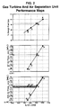
- Fig. 2 The relationship among the IGCC system operating capacity, the gas turbine operation, and the air separation unit operation at full and part load conditions is illustrated in Fig. 2 for a typical IGCC operation at a constant ambient temperature.
- % of gas turbine (GT) design fuel gas capacity, gas turbine (GT) air compressor discharge pressure, and air separation unit (ASU) operating pressure are plotted against the % of design load for the gas turbine (GT) system.
- the slopes of these operating lines are characteristic of a particular gas turbine system design and ambient conditions.
- gas turbine air compressor 3 operates at a discharge pressure of 190 psia (1.3 MPa) and air separation unit 39 operates at the same pressure, which means that the discharge pressure of main air compressor 43 is also 190 psia (1.3 MPa).
- the gas turbine air compressor discharge pressure will decrease according to points B, C, and D in the middle graph, and as a result the air separation unit must operate at the same decreasing pressure levels as shown by points B, C, and D in the lower graph. Since the air extraction rate is determined according to the usual design practice, and since the total air feed to the air separation unit decreases due to lower oxygen demand, the throughput of air through main air compressor 43 and the mass flow of extracted air 37 will decrease.
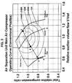
- compressors 43, 51, 61, and 67 associated with air separation unit 39 be designed to operate over wide ranges of volumetric flow and compression ratios corresponding to the operating points A through D in Fig. 2. This is illustrated in Fig. 3 which gives compressor operating curves for main air compressor 43 operating over a full range of flow and compression ratio corresponding to operation of the integrated IGCC system from points A to D described in Fig. 2.
- two pressures are considered essentially equal if they are within 5 psi (35 kPa), and a pressure is considered essentially constant if it varies less than 1% on an absolute pressure basis.
- the term "relative compression ratio” means the compression ratio of a compressor at any operating point divided by the compression ratio at a selected design point.
- the term "relative suction volume flow” is defined as the actual volumetric flow at the compressor inlet at any operating point divided by the actual volumetric flow at the compressor inlet at a selected design point.
- the compressor operating curves of Figs. 3 to 6 for constant ambient temperature indicate lines of constant relative efficiency which is defined as the actual compressor efficiency divided by the efficiency at a fixed reference condition, n/n ref .
- the efficiency curves are bounded at higher compression ratios by the compressor surge line as shown. At low relative suction volume flow, the efficiency curves are bounded by the minimum flow curve which represents compressor operation when the compressor guide vanes are closed to the maximum degree possible. At higher relative suction volume flow, the efficiency curves are bounded by the maximum flow curve which represents compressor performance when the guide vanes are reversed in the maximum flow configuration.
- the neutral guide vane opening curve as shown passes through the reference point at which the relative suction volume flow and total relative compression ratio are 1.0.
- main air compressor 43 operates at point A at maximum throughput with inlet guide vanes in the maximum flow position.
- the relative compressor efficiency for point A is about 0.985.
- the air compressor operation moves to point B as the relative suction volume flow and total relative compression ratio decrease as earlier described.
- point C is the compressor minimum operating capacity with compressor guide vanes closed as far as mechanically possible.
- compressor efficiency is high at maximum capacity represented by point A and low at extreme turndown conditions represented by points C and D.
- Fig. 4 gives compressor operating curves for oxygen product compressor 51 operating over a full range of flow and compression ratios corresponding to the gas turbine system operating range described above for Fig. 3.
- the oxygen product compressor operates at point A.
- points B and C As turndown increases, the oxygen compressor operation moves successively to points B and C, and finally to point D at maximum turndown, at which point the compressor operates at maximum volumetric throughput with the compressor guide vanes in the maximum flow position.
- the compressor In order to allow compressor operability over the entire turndown range, the compressor must operate at point A in a region of low relative efficiency at gas turbine system design operating capacity.
- oxygen product compressor 51 operates at high efficiency at maximum turndown and low efficiency at normal system design capacity. This is an undesirable operating situation, since the compressor will perform at a low efficiency for a considerable fraction of the onstream time. Similar problems occur with nitrogen product compressors 61 and 67, which have operating curves similar to Fig. 3.
- the present invention addresses this undesirable operating situation by limiting the use of extracted air to a portion of the turndown region defined between points A (gas turbine design capacity or full load) and B of Fig. 2, and supplying air to the air separation unit only by main air compressor 43 at gas turbine operating loads below Point B.
- the air separation unit operates at a relatively constant pressure in the turndown region below point B, for example in the range of 160 to 165 psia (1.1 - 1.15 MPa) as shown, and no extracted air is used for air separation unit feed. Since all air from gas turbine air compressor 3 in this operating mode would pass to combustor 11, the firing temperature may decrease since less fuel 9 is being fired at turndown; however, mass flow through combustion turbine 15 would be higher and the efficiency of the expansion turbine would not suffer appreciably.
- the air separation unit operates between points A and B in the lower graph of Fig. 2 at decreasing pressure with feed air supplied by main air compressor discharge 45 and extracted air 37.
- points B and D* (maximum turndown) air separation unit 39 and main air compressor 43 operate at essentially constant pressure.
- Gas turbine air compressor 3 will still operate between points A and D in the middle graph of Fig. 2, but between points B and D the flow of extracted air 37 will be zero and all compressed air 5 would pass to combustor 11.
- Point B is defined by the preferred minimum operating pressure of air separation unit 39, which for the example in Fig. 2 is between 160 and 165 psia (1.1 - 1.15 MPa). This minimum pressure will vary with gas turbine and air separation unit design requirements, and typically will be in the range of 120 to 260 psig (0.85 - 1.8 MPa).
- the pressure of oxygen and nitrogen products 47 and 49 will be higher for the present invention than for the typical operating practice between points B and D (Fig. 2).
- the oxygen and nitrogen product pressures and the air separation feed pressure will be essentially constant, in contrast with decreasing pressures between operating points B, C, and D as in typical operating practice.
- This feature of the invention allows the operation of main air compressor 43 and product compressors 51, 61, and 67 over a much narrower range of compression ratios. This in turn enables more efficient compressor operation as described below.
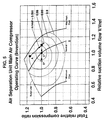
- Fig. 5 gives compressor operating curves for main air compressor 43 designed to operate according to the present invention.
- the compressor operates at point A, and as turndown occurs the compressor operates between points A and B (these points correspond to points A and B in Fig. 2).
- points B, C*, and D* the compressor operates at a constant discharge pressure and compression ratio.
- the minimum design total compression ratio is defined as the compression ratio when the compressor operates between points B, C*, and D*.
- the maximum design relative suction pressure is defined by Point B.
- Fig. 6 gives compressor operating curves for oxygen product compressor 51 designed to operate according to the present invention.
- the compressor operates at point A, and as turndown proceeds the compressor operates between points A and B (these points correspond to points A and B in Fig. 2).
- the maximum design total relative compression ratio is defined as the ratio when operating between points B, C*, and D*.
- Point B defines the maximum design relative suction volume flow.
- the relative operating efficiency at point A (which occurs for the largest fraction of IGCC operating time) is about 0.99 according to the present invention. In contrast, the relative efficiency at the corresponding point A in Fig.
- nitrogen product compressors 61 and 67 When air extraction is used over the entire range of gas turbine and air separation system turndown according to usual practice, nitrogen product compressors 61 and 67 will exhibit operating characteristics similar to those of oxygen product compressor 51 as illustrated in Fig. 4. When air separation unit 39 is operated according to the present invention, nitrogen product compressors 61 and 67 can be designed and operated in the same manner as oxygen product compressor 51 illustrated in Fig. 6. Thus higher operating efficiencies can be realized for all three product compressors 51, 61, and 67 according to the present invention when the gas turbine system operates at design capacity.
- the definitions of maximum design total relative compression ratio and maximum design relative suction volume flow for nitrogen compressors 61 and 67 are the same definitions given above for oxygen product compressor 51.
- the IGCC system of Fig. 1 was simulated to compare the overall efficiency of the air separation plant operation according to (1) current practice in which the feed to air separation unit 39 includes some extracted air 37 over the entire air separation unit operating range and (2) operation according to the present invention in which air extraction is used only above an air separation unit feed pressure of 147 psia (1.015 MPa).
- turndown occurs in most cases because of changes in ambient temperature as will be seen below.
- design capacity analogous to point A in Figs. 3-6
- the average actual compression ratios are as follows: 13.0 for gas turbine compressor 3, 13.0 for main air compressor 43, 10.0 for oxygen compressor 51, and 5.0 for return nitrogen compressor 67.
- At maximum turndown or minimum flow analogous to point D in Fig.
- Air separation unit 39 is sized to provide the necessary oxygen and nitrogen for the IGCC system with no export of product oxygen or nitrogen.
- the IGCC system operates at ambient temperatures of 23, 41, 59, 75, and 95°F (-5, 5, 15, 24 & 35 °C) and the compressor efficiencies are calculated for main air compressor 43, oxygen product compressor 51, and return nitrogen compressor 67 for each of these temperatures at full load and for selected temperatures at part load.
- the relative efficiencies at full load for each compressor were averaged for ambient temperatures of 41, 59, and 95°F (5, 15 & 35 °C), and these average efficiencies were used to calculate the average efficiency ratio for each compressor.
- This average efficiency ratio is defined as the average relative efficiency for the method of the present invention divided by the average relative efficiency for current practice.
- the total power consumption for each of the three air separation unit compressors was calculated for the case in which the compressors are designed to operate according to the current practice of air extraction to the air separation unit over the entire IGCC operating range, and the results were normalized to give the relative power consumption of each compressor.
- the average efficiency ratios determined above were utilized with the relative power consumption to calculate the relative power consumption for each of the compressors designed according to the present invention.
- the results are given in Table 4 and show that at full load IGCC design capacity the overall power consumed by the air separation unit according to the present invention is 3.3% lower than the corresponding consumption when the unit is operated according to current practice.
- the present invention allows the air separation unit of an IGCC power generation system to operate in a more efficient manner compared with operation according to current practice. Because the air separation unit compressors are designed to operate over a narrower range of compression ratios, more efficient overall operation is realized chiefly because the oxygen and nitrogen product compressors operate at high efficiency when the IGCC system operates at full design load. When product compressors must be designed to operate over a wide range of compression ratios, which is the case when extracted air is utilized across the entire IGCC operating range, these compressors operate at significantly lower efficiencies when the IGCC system operates at full load. In addition, by operating the air separation unit continuously over the entire range of IGCC loads, the inefficiencies associated with startup and shutdown of the main air compressor for the air separation unit are avoided.
Landscapes
- Engineering & Computer Science (AREA)
- Mechanical Engineering (AREA)
- General Engineering & Computer Science (AREA)
- Physics & Mathematics (AREA)
- Thermal Sciences (AREA)
- Chemical & Material Sciences (AREA)
- Combustion & Propulsion (AREA)
- Health & Medical Sciences (AREA)
- Emergency Medicine (AREA)
- Power Engineering (AREA)
- Separation By Low-Temperature Treatments (AREA)
- Engine Equipment That Uses Special Cycles (AREA)
Abstract
Description
- The invention pertains to the operation of an integrated gasification combined cycle power generation system and in particular to a method for operating the gas turbine and air separation unit when the power generation system operates at less than design load.
- The generation of electricity by advanced gasification combined cycle power generation systems offers the potential for reduced power cost and lower environmental impact than standard coal-fired power plants. In these advanced systems, coal or other carbonaceous material is gasified with oxygen and the produced gas is cleaned to yield a low-sulfur fuel gas. This fuel gas is utilized in a gas turbine generation system to produce electric power with reduced environmental emissions. The growing interest in gasification combined cycle (GCC) technology in recent years has been stimulated by the higher efficiency and demonstrated reliability of advanced gas turbines, coal gasification processes, and air separation systems which are utilized in integrated gasification combined cycle (IGCC) systems. The proper integration of these three main components of an IGCC system is essential to achieve maximum operating efficiency and minimum power cost.
- A general review of the current art in GCC and IGCC power generation systems is given by D. M. Todd in an article entitled "Clean Coal Technologies for Gas Turbines" presented at the GE Turbine State-of-the-Art Technology Seminar, July 1993, pp. 1-18. A. K. Anand et al present a review of the factors involved in the design of IGCC systems in a paper entitled "New Technology Trends for Improved IGCC System Performance" presented at the International Gas Turbine and Aeroengine Congress and Exposition, Houston, Texas, June 5-8, 1995. A review of various integration techniques and the impact thereof on GCC economics is given in a paper by A. D. Rao et al entitled "Integration of Texaco TQ Gasification with Elevated Pressure ASU" presented at the 13th EPRI Conference on Gasification Power Plants, San Francisco, CA, October 19-21, 1994.
- In a paper entitled "Improved IGCC Power Output and Economics Incorporating a Supplementary Gas Turbine" presented at the 13th EPRI Conference on Gasification Power Plants, San Francisco, CA, October 19-21, 1994, A. R. Smith et al review several modes of integration between the gas turbine and the air separation unit in an IGCC process. In one mode, the air separation unit feed air is provided by a separate compressor and a portion of the nitrogen product from the air separation unit is compressed and introduced into the gas turbine combustor. This nitrogen-integrated mode allows operation of the IGCC system at increased gas turbine power output and reduced NOx formation. In an alternative operating mode, nitrogen integration is combined with air integration in which a portion of the feed air to the air separation unit is supplied by extracted air from the gas turbine compressor. This alternative mode, defined as air and nitrogen integration, gives greater operating flexibility and allows for a higher degree of optimization during IGCC system operation at part load and other off-design conditions.
- Air- and nitrogen-integrated gas turbine/air separation systems are described by representative US-A-3,731,495, US-A-4,019,314, US-A-4,224,045, US-A-4,557,735, US-A-4,697,415, US-A-5,081,845, US-A-5,386,686, US-A-5,406,786, and US-A-5,410,869, and GB-A-2067668.
- Combustion-based power generation systems, including IGCC systems, are subject to periods of operation below system design capacity due to changes in ambient air temperature and/or the cyclic demand for electric power. During these periods, such systems operate below design efficiency. The equipment selection and process design of an IGCC system therefore must address steady-state operation at design capacity as well as operation at off-design, part load, or turndown conditions. The air- and nitrogen-integrated IGCC system described above is a preferred option because of the potential for operating such a system at maximum overall efficiency, particularly when the system also must operate at off-design, part load, or turndown conditions.
- The invention disclosed below and defined by the claims which follow addresses the need for improved methods to operate advanced power generation systems, and in particular describes the improved operation of air- and nitrogen-integrated gas turbine and air separation systems at part load or turndown conditions.
- The invention is a method of operating an integrated gas turbine/air separation system at part load which comprises compressing air in a gas turbine air compressor, combusting at least a portion of the resulting compressed air with a fuel in a gas turbine combustor to form hot combustion products, expanding the hot combustion products in a gas turbine expander which drives the compressor and optionally an electric generator. Air is separated into nitrogen-rich and oxygen-rich products in a cryogenic air separation unit wherein feed air to the air separation unit is provided by a main air compressor and optionally by an additional portion of compressed air from the gas turbine air compressor. The integrated gas turbine/air separation system is operated at part load such that
- (a) when the gas turbine air compressor supplies compressed air at a given operating pressure which is greater than a minimum air separation unit feed pressure, the air separation unit is operated at a feed pressure essentially equal to the given operating pressure and the feed air is provided to the air separation unit by the main air compressor with the additional portion of compressed air from the gas turbine air compressor; and
- (b) when the gas turbine air compressor supplies compressed air at a given operating pressure which is essentially equal to or less than the minimum air separation unit feed pressure, the air separation unit is operated at a feed pressure essentially equal to the minimum air separation unit feed pressure and the feed air to the air separation unit is provided by the main air compressor without additional compressed air from the gas turbine air compressor.
- The minimum air separation unit feed pressure usually is between 80 and 500 psia (0.55 - 3.5 MPa).
- The main air compressor operates in either of two modes such that
- (a) when the main air compressor operates at a discharge pressure which is greater than the minimum air separation unit feed pressure, the main air compressor is operated above its minimum design total relative compression ratio and below its maximum design relative suction volume flow; and
- (b) when the main air compressor operates at a discharge pressure which is essentially equal to the minimum air separation unit feed pressure, the main air compressor is operated essentially at its minimum design total relative compression ratio and at or below its maximum design relative suction volume flow.
- The minimum design total relative compression ratio and the maximum design relative suction volume flow of the main air compressor occur essentially at the minimum air separation unit feed pressure. The main air compressor usually operates at a discharge pressure between 80 and 600 psia (0.55 - 4 MPa).
- The oxygen-rich product is compressed in an oxygen compressor which operates in either of two modes such that
- (a) when the main air compressor operates at a discharge pressure which is greater than the minimum air separation unit feed pressure, the oxygen compressor is operated below its maximum design total relative compression ratio and below its maximum design relative suction volume flow; and
- (b) when the main air compressor operates at a discharge pressure which is essentially equal to the minimum air separation unit feed pressure, the oxygen compressor is operated essentially at its maximum design total relative compression ratio and at or below its maximum design relative suction volume flow.
- The maximum design total relative compression ratio and the maximum design relative suction volume flow of the oxygen compressor occur when the main air compressor operates at a discharge pressure which is essentially equal to the minimum air separation unit feed pressure. The oxygen compressor usually operates at a discharge pressure between 120 and 2000 psia (0.85 - 14 MPa).
- Fuel gas for the gas turbine combustor can be generated in a process for gasifying a carbonaceous feedstock with compressed oxygen-rich product from the air separation unit.
- At least a portion of the nitrogen-rich product can be compressed in a nitrogen compressor for use in the process for gasifying the carbonaceous feedstock. The nitrogen compressor operates in either of two modes such that
- (a) when the main air compressor operates at a discharge pressure which is greater than the minimum air separation unit feed pressure, the nitrogen compressor is operated below its maximum design total relative compression ratio and below its maximum design relative suction volume flow; and
- (b) when the main air compressor operates at a discharge pressure which is essentially equal to the minimum air separation unit feed pressure, the nitrogen compressor is operated essentially at its maximum design total relative compression ratio and at or below its maximum design relative suction volume flow.
- The maximum design total relative compression ratio and the maximum design relative suction volume flow of the nitrogen compressor occur when the main air compressor operates at a discharge pressure which is essentially equal to the minimum air separation unit feed pressure. The nitrogen compressor usually operates at a discharge pressure between 50 and 2000 psia (0.35 - 14 MPa).
- At least a portion of the nitrogen-rich product can be compressed in a nitrogen compressor and introduced into the gas turbine combustor. In this option, the nitrogen compressor operates in either of two modes such that
- (a) when the main air compressor operates at a discharge pressure which is greater than the minimum air separation unit feed pressure, the nitrogen compressor is operated below its maximum design total relative compression ratio and below its maximum design relative suction volume flow; and
- (b) when the main air compressor operates at a discharge pressure which is essentially equal to the minimum air separation unit feed pressure, the nitrogen compressor is operated essentially at its maximum design total relative compression ratio and at or below its maximum design relative suction volume flow.
- The maximum design total relative compression ratio and the maximum design relative suction volume flow of the nitrogen compressor occur when the main air compressor operates at a discharge pressure which is essentially equal to the minimum air separation unit feed pressure. The nitrogen compressor usually operates at a discharge pressure between 120 and 2000 psia (0.85 - 14 MPa).
- By designing the air separation unit feed and product compressors as described by the invention, the gas turbine system operates at part load with a slight penalty in total power consumption for the air separation unit. However, because the main air compressor, oxygen product compressor, and nitrogen product compressors are designed to operate over a relatively narrow range of compression ratio and suction volume flow, the compressor efficiencies at the gas turbine system full load design capacity (where the system operates most of the time) are maximized and the total power consumption for the air separation unit is minimized.
- The following is a description by way of example only and with reference to the accompanying drawings of embodiments of the invention. In the drawings:-
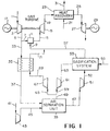
- Fig. 1 is a flow diagram of an integrated gasification combined cycle power generation system with air and nitrogen integration;
- Fig. 2 is a performance map for the operation of the integrated gasification combined cycle power generation system of Fig. 1 at or below design capacity;
- Fig. 3 provides compressor operating curves for the air separation main air compressor operating over a full range of compressor operation according to conventional practice;
- Fig. 4 provides compressor operating curves for the air separation product oxygen compressor operating over a full range of compressor operation according to conventional practice;
- Fig. 5 provides compressor operating curves for the air separation main air compressor operating over the range of the present invention; and
- Fig. 6 provides compressor operating curves for the air separation product oxygen compressor operating over the range of the present invention.
- The invention relates to integrated gas turbine/air separation systems in which the gas turbine and air separation units are linked by the transfer of at least one gas stream from one system to the other. For example, in an air-integrated gas turbine/air separation system some or all of the compressed air feed to the air separation unit is provided by the gas turbine compressor during at least a portion of the system operating time. In a nitrogen-integrated gas turbine/air separation system some or all of the nitrogen product from the air separation unit is introduced into the gas turbine combustor during at least a portion of the system operating time.
- Air and nitrogen integration is preferred for use in integrated gasification combined cycle (IGCC) systems in many applications because of the potential for operation at maximum overall efficiency, particularly when the system operates at part load or turndown conditions for certain periods of time. An air- and nitrogen-integrated IGCC process is illustrated in Fig. 1 wherein ambient air 1 is compressed in gas turbine air compressor 3, which is typically an axial flow adiabatic compressor, to 150 to 450 psia (1 - 3 MPa) at 600°F to 900°F (325 - 475 °C). A portion 7 of
compressed air 5 is combusted withfuel 9 in gas turbine combustor 11 to yieldcombustion product stream 13 typically at 2000°F to 2800°F (1100 - 1550 °C).Fuel 9 preferably is a gaseous fuel such as synthesis gas or natural gas, although liquid fuels may be utilized as well.Combustion product stream 13 is expanded ingas turbine expander 15 to generate shaft power which drives compressor 3 andelectric generator 17. Optionally,turbine exhaust 19 at 0.2 to 2 psig (1.5 - 15 kPa) and 900°F to 1100°F (475 - 600 °C) is cooled againstboiler feedwater 21 inheat recovery zone 23 to generatesteam 25 which is expanded insteam turbine 27 to drive additionalelectric generator 29.Generators Final exhaust 31 is discharged to the atmosphere. - Extracted
air 33, which is the remaining portion ofcompressed air 5, is cooled against nitrogen stream 69 (later defined) inheat exchange zone 35 to 300°F to 900°F (150 - 475 °C) and providesfeed air 37 toair separation unit 39. The remaining feed air is provided by compressingair 41 inmain air compressor 43 to providefeed air 45 toair separation unit 39.Main air compressor 43 is an intercooled centrifugal machine which providesfeed air 45 at 40°F to 120°F (5 - 50 °C) and essentially the same pressure as cooled extractedair 37. - In usual design practice, the amount of extracted
air 33 as a percentage of the total air separation unit feed requirement is fixed for a given ambient air temperature. Theterm 50% extracted air, for example, means that extractedair 33 provides 50% of the total feed air toair separation unit 39, and the remaining 50% is supplied bymain air compressor 43. 100% extracted air means that all feed air forair separation unit 39 is supplied from gas turbine air compressor 3 and air frommain air compressor 43 is not required. - Extracted
air 37 and feedair 45 flow to cryogenicair separation unit 39 wherein impurities are removed from the air, and the air is cooled, condensed, and distilled to yieldoxygen product 47, typically containing 80 to 99.9 vol% oxygen, andnitrogen product 49, typically containing 96 to 99.9 vol% nitrogen.Oxygen product 47 is compressed to 200 to 1200 psia (1.5 - 14 MPa) inoxygen compressor 51 to provideoxygen 52 togasification system 53 which convertscarbonaceous feedstock 55 intofuel gas 57 comprising chiefly hydrogen and carbon monoxide. - Cryogenic air separation processes for use in IGCC systems are well-known, and representative processes are described in US-A-4,224,045, US-A-5,081,845, and US-A-5,224,336. Commercially-available gasification systems for this application have been developed by Texaco, Shell, BG-Lurgi, Prenflo, HTW, and Destec. Such feedstocks include coal, coke, vacuum residua, and other heavy hydrocarbons. A
portion 59 ofnitrogen product 49 is compressed to 50 to 2000 psia (0.35 - 14 MPa) innitrogen compressor 61 to providecompressed nitrogen 63 for purging, soot blowing, and coal conveying ingasification system 53. - The present invention is not restricted to IGCC systems as described above, and can be used for any air-integrated combustion turbine/air separation system which operates below design capacity for certain periods of time. In an alternative mode of operation, referring to Fig. 1,
gasification system 53 is not used andcompressed oxygen product 52 is provided at pressure for external use. Optionally,nitrogen 59 is compressed innitrogen compressor 61 to provideproduct nitrogen 63 for external use. Optionally and preferably,nitrogen 65 is combined withfuel 57 and introduced into combustor 11 as fuel-nitrogen mixture 9 or compressed innitrogen compressor 67 and introduced directly into combustor 11 (not shown).Fuel 57 is provided from an external source, for example as natural gas. Optionally,electric generators oxygen 52 and/ornitrogen 63. In this case compressor 3, combustor 11,expansion turbine 15, andsteam turbine 27 would be sized to provide only the power required for the air separation system. For any of these alternatives, during operation of the gas turbine system at part load or turndown conditions,air separation unit 39 will operate according to the description given above. -
Fuel gas 57 providesfuel 9 at a pressure of 200 to 600 psia (1.5 - 4 MPa) and typically has a heating value of 150 to 450 BTU/SCF (5 - 15 J/SCM) when produced bygasifier 53 or about 1000 BTU/SCF (35 J/SCM) when provided as natural gas. Anotherportion 65 ofnitrogen product 49 is compressed to 150 to 600 psia (1 - 4 MPa) innitrogen compressor 67, warmed against extractedair 33 inheat exchange zone 35, and combined vialine 71 withfuel gas 57 to yield fuel-nitrogen mixture for introduction into gas turbine combustor 11. Alternatively, warmcompressed nitrogen 71 can be introduced directly into combustor 11. The use of warmcompressed nitrogen 71 in the gas turbine reduces the formation of nitrogen oxides in combustor 11 and increases power output ofexpansion turbine 15. - Designing a commercial IGCC power plant which uses the process described above is an iterative process which involves the optimum selection of the gas turbine, air separation, and gasification systems to satisfy the operating requirements for power generation. These requirements include the design capacity as a function of ambient temperature for the actual plant location, the design maximum ambient temperature, the design maximum power output, the maximum gas turbine firing temperature, the amount of extracted air, the daily and seasonal power demand profiles, the relative importance of capital vs. operating costs for the project, and other requirements.
- The object of the present invention is to determine the proper amount of air extraction, the preferred operating mode of the air separation unit, and the required design points for the air separation unit feed and product compressors which will allow optimum gas turbine/air separation unit operation during swings in gas turbine output as a result of lower power demand and/or changes in ambient air temperature.
- Operation of a gas turbine at less than design power output is referred to herein as part load or turndown operation. Two operating variables can reduce the power output of the gas turbine in the IGCC process of Fig. 1. The first of these is an increase in ambient air temperature, which decreases the density of feed air 1 and in turn reduces the mass flow of
compressed air 5 and the amount ofcompressed air 33 which can used for feed to airseparation unit 39. In order to operate below the maximum temperature limitation ofgas turbine expander 15, the firing rate of combustor 11 must be reduced by decreasing the flow offuel 9. This in turn reduces the mass flow ofcombustion products 13 and the power output ofexpander 15. As a result, a 10°C increase in ambient air temperature can reduce power output by 4% for a typical IGCC system. - The second operating variable which decreases the power output of the gas turbine in the IGCC system is the reduction in power demand which occurs in the typical daily power demand cycle. For example, the nighttime power demand on a typical IGCC plant can be 50-75% of the daytime demand. Seasonal changes in power demand also may occur. During reduced power demand, the plant must be operated at part load (i.e. "turned down") by decreasing the flow of air and fuel to the gas turbine combustor. Gas turbine air compressor 3 can be turned down by throttling inlet air 1 using guide vanes at the inlet of compressor 3 or by recirculating air within the compressor system. As a result, the mass flow and the pressure of
compressor discharge 5 decrease, which reduces the pressure of extractedair 37 toair separation unit 39. This in turn requires thatmain air compressor 43 must operate at a reduced discharge pressure, andair separation unit 39 therefore must operate at a lower pressure which decreases the pressure ofoxygen product 47 andnitrogen product 49. However,gasification system 53 typically operates at a fixed pressure, so thatoxygen compressor 51 andnitrogen compressor 61 must operate at higher compression ratios at turndown conditions. Becauseless fuel 57 is required at turndown,less oxygen 47 is required bygasification system 53, and therefore less feed air is required byair separation unit 39. - As stated earlier, it is current design practice to fix the air extraction rate for a given ambient air temperature and design load. During turndown the feed for
air separation unit 39 continues to be provided by both extractedair 37 andcompressed feed air 45.Main air compressor 43 therefore must be designed to operate over wide ranges of air flow and compression ratio in order to cover the entire IGCC operating range between full design capacity and maximum turndown. As the operating pressure ofair separation unit 39 varies over this wide range, the suction pressures of oxygen andnitrogen compressors main air compressor 43 and supply the air separation unit completely by extractedair 37. - The relationship among the IGCC system operating capacity, the gas turbine operation, and the air separation unit operation at full and part load conditions is illustrated in Fig. 2 for a typical IGCC operation at a constant ambient temperature. In this performance map, the % of gas turbine (GT) design fuel gas capacity, gas turbine (GT) air compressor discharge pressure, and air separation unit (ASU) operating pressure are plotted against the % of design load for the gas turbine (GT) system. The slopes of these operating lines are characteristic of a particular gas turbine system design and ambient conditions. At point A, which represents the design IGCC system gas turbine power output, gas turbine air compressor 3 operates at a discharge pressure of 190 psia (1.3 MPa) and
air separation unit 39 operates at the same pressure, which means that the discharge pressure ofmain air compressor 43 is also 190 psia (1.3 MPa). As the gas turbine is turned down and operated at successively lower outputs as defined by points B, C, and D in the upper graph of Fig. 2, the gas turbine air compressor discharge pressure will decrease according to points B, C, and D in the middle graph, and as a result the air separation unit must operate at the same decreasing pressure levels as shown by points B, C, and D in the lower graph. Since the air extraction rate is determined according to the usual design practice, and since the total air feed to the air separation unit decreases due to lower oxygen demand, the throughput of air throughmain air compressor 43 and the mass flow of extractedair 37 will decrease. - The standard practice of varying pressure and flow of extracted
air 33 over the entire gas turbine operating range therefore requires thatcompressors air separation unit 39 be designed to operate over wide ranges of volumetric flow and compression ratios corresponding to the operating points A through D in Fig. 2. This is illustrated in Fig. 3 which gives compressor operating curves formain air compressor 43 operating over a full range of flow and compression ratio corresponding to operation of the integrated IGCC system from points A to D described in Fig. 2. - In the present specification and appended claims, two pressures are considered essentially equal if they are within 5 psi (35 kPa), and a pressure is considered essentially constant if it varies less than 1% on an absolute pressure basis. The term "relative compression ratio" means the compression ratio of a compressor at any operating point divided by the compression ratio at a selected design point. The term "relative suction volume flow" is defined as the actual volumetric flow at the compressor inlet at any operating point divided by the actual volumetric flow at the compressor inlet at a selected design point. The compressor operating curves of Figs. 3 to 6 for constant ambient temperature indicate lines of constant relative efficiency which is defined as the actual compressor efficiency divided by the efficiency at a fixed reference condition, n/nref. The efficiency curves are bounded at higher compression ratios by the compressor surge line as shown. At low relative suction volume flow, the efficiency curves are bounded by the minimum flow curve which represents compressor operation when the compressor guide vanes are closed to the maximum degree possible. At higher relative suction volume flow, the efficiency curves are bounded by the maximum flow curve which represents compressor performance when the guide vanes are reversed in the maximum flow configuration. The neutral guide vane opening curve as shown passes through the reference point at which the relative suction volume flow and total relative compression ratio are 1.0.
- Referring again to Fig. 3, at the design operating capacity of the gas turbine system,
main air compressor 43 operates at point A at maximum throughput with inlet guide vanes in the maximum flow position. The relative compressor efficiency for point A is about 0.985. As the IGCC system is operated at decreasing capacity due to reduced power demand, the air compressor operation moves to point B as the relative suction volume flow and total relative compression ratio decrease as earlier described. As further turndown occurs, the compressor operating condition moves to point C and finally to point D, which is the compressor minimum operating capacity with compressor guide vanes closed as far as mechanically possible. Thus compressor efficiency is high at maximum capacity represented by point A and low at extreme turndown conditions represented by points C and D. - Fig. 4 gives compressor operating curves for
oxygen product compressor 51 operating over a full range of flow and compression ratios corresponding to the gas turbine system operating range described above for Fig. 3. At the design operating capacity of the system, the oxygen product compressor operates at point A. As turndown increases, the oxygen compressor operation moves successively to points B and C, and finally to point D at maximum turndown, at which point the compressor operates at maximum volumetric throughput with the compressor guide vanes in the maximum flow position. In order to allow compressor operability over the entire turndown range, the compressor must operate at point A in a region of low relative efficiency at gas turbine system design operating capacity. - As a result of this required wide design range,
oxygen product compressor 51 operates at high efficiency at maximum turndown and low efficiency at normal system design capacity. This is an undesirable operating situation, since the compressor will perform at a low efficiency for a considerable fraction of the onstream time. Similar problems occur withnitrogen product compressors - The present invention addresses this undesirable operating situation by limiting the use of extracted air to a portion of the turndown region defined between points A (gas turbine design capacity or full load) and B of Fig. 2, and supplying air to the air separation unit only by
main air compressor 43 at gas turbine operating loads below Point B. The air separation unit operates at a relatively constant pressure in the turndown region below point B, for example in the range of 160 to 165 psia (1.1 - 1.15 MPa) as shown, and no extracted air is used for air separation unit feed. Since all air from gas turbine air compressor 3 in this operating mode would pass to combustor 11, the firing temperature may decrease sinceless fuel 9 is being fired at turndown; however, mass flow throughcombustion turbine 15 would be higher and the efficiency of the expansion turbine would not suffer appreciably. - Thus in the present invention the air separation unit operates between points A and B in the lower graph of Fig. 2 at decreasing pressure with feed air supplied by main
air compressor discharge 45 and extractedair 37. Between points B and D* (maximum turndown)air separation unit 39 andmain air compressor 43 operate at essentially constant pressure. Gas turbine air compressor 3 will still operate between points A and D in the middle graph of Fig. 2, but between points B and D the flow of extractedair 37 will be zero and allcompressed air 5 would pass to combustor 11. Point B is defined by the preferred minimum operating pressure ofair separation unit 39, which for the example in Fig. 2 is between 160 and 165 psia (1.1 - 1.15 MPa). This minimum pressure will vary with gas turbine and air separation unit design requirements, and typically will be in the range of 120 to 260 psig (0.85 - 1.8 MPa). - By operating the air separation unit at or above a selected minimum operating pressure during turndown, the pressure of oxygen and
nitrogen products main air compressor 43 andproduct compressors - Fig. 5 gives compressor operating curves for
main air compressor 43 designed to operate according to the present invention. At full design gas turbine operating capacity, the compressor operates at point A, and as turndown occurs the compressor operates between points A and B (these points correspond to points A and B in Fig. 2). Between points B, C*, and D* the compressor operates at a constant discharge pressure and compression ratio. The minimum design total compression ratio is defined as the compression ratio when the compressor operates between points B, C*, and D*. The maximum design relative suction pressure is defined by Point B. - Fig. 6 gives compressor operating curves for
oxygen product compressor 51 designed to operate according to the present invention. At full design IGCC operating capacity, the compressor operates at point A, and as turndown proceeds the compressor operates between points A and B (these points correspond to points A and B in Fig. 2). Between points B, C*, and D* the compressor operates at a constant discharge pressure and compression ratio. The maximum design total relative compression ratio is defined as the ratio when operating between points B, C*, and D*. Point B defines the maximum design relative suction volume flow. The relative operating efficiency at point A (which occurs for the largest fraction of IGCC operating time) is about 0.99 according to the present invention. In contrast, the relative efficiency at the corresponding point A in Fig. 4, which describes typical operation at design gas turbine capacity without use of the present invention, is only about 0.85. Thus the method of the present invention allows the design and operation of the oxygen product compressor over a narrower range of total relative compression ratio and relative suction volume flow, which in turn enables more efficient overall operation of the compressor. - When air extraction is used over the entire range of gas turbine and air separation system turndown according to usual practice,
nitrogen product compressors oxygen product compressor 51 as illustrated in Fig. 4. Whenair separation unit 39 is operated according to the present invention,nitrogen product compressors oxygen product compressor 51 illustrated in Fig. 6. Thus higher operating efficiencies can be realized for all threeproduct compressors nitrogen compressors oxygen product compressor 51. - Prior methods to improve the efficiencies of gas turbines and air separation units in IGCC systems are extensive, but it was not realized that limiting the air extraction from the gas turbine compressor to the air separation unit during turndown and increasing the role of the air separation unit main air compressor can improve overall efficiency and reduce cost of electricity. This is an unexpected conclusion in view of the prior art, since during turndown according to the present invention the combustion turbine may operate somewhat inefficiently (extracted air may be vented or a lower combustor firing temperature may occur) and the standalone air separation compressor must share more of the load. Operation of the air separation unit product compressors is less severe in the present invention; since turndown operation determines compressor selection, these compressors can be designed for more efficient full load operation.
- The IGCC system of Fig. 1 was simulated to compare the overall efficiency of the air separation plant operation according to (1) current practice in which the feed to
air separation unit 39 includes some extractedair 37 over the entire air separation unit operating range and (2) operation according to the present invention in which air extraction is used only above an air separation unit feed pressure of 147 psia (1.015 MPa). In this Example, turndown occurs in most cases because of changes in ambient temperature as will be seen below. At design capacity (analogous to point A in Figs. 3-6) the average actual compression ratios are as follows: 13.0 for gas turbine compressor 3, 13.0 formain air compressor 43, 10.0 foroxygen compressor 51, and 5.0 forreturn nitrogen compressor 67. At maximum turndown or minimum flow, analogous to point D in Fig. 2, the average actual compression ratios are as follows: 9.0 for gas turbine compressor 3, 9.0 formain air compressor 43, 18.0 foroxygen compressor 51, and 6.5 forreturn nitrogen compressor 67. These compression ratios are representative of "F" technology gas turbines.Air separation unit 39 is sized to provide the necessary oxygen and nitrogen for the IGCC system with no export of product oxygen or nitrogen. The IGCC system operates at ambient temperatures of 23, 41, 59, 75, and 95°F (-5, 5, 15, 24 & 35 °C) and the compressor efficiencies are calculated formain air compressor 43,oxygen product compressor 51, and returnnitrogen compressor 67 for each of these temperatures at full load and for selected temperatures at part load. - The calculated results for operation according to current practice (air extraction to the air separation unit over the entire gas turbine operating range) are given in Table 1 and calculated results for operation according to the present invention (air extraction to the air separation unit only above air separation unit feed pressure of 147 psia (1.015 MPa)) are given in Table 2. The relative compressor efficiencies for the two cases and three compressors were compared at full load at 41, 59, and 95°F (5, 15 & 35 °C) and the results are summarized in Table 3. It is seen that relative efficiencies for the main air compressor are slightly less for the invention than for current design practice, but are significantly higher for the oxygen and nitrogen compressors in the present invention.
- The relative efficiencies at full load for each compressor were averaged for ambient temperatures of 41, 59, and 95°F (5, 15 & 35 °C), and these average efficiencies were used to calculate the average efficiency ratio for each compressor. This average efficiency ratio is defined as the average relative efficiency for the method of the present invention divided by the average relative efficiency for current practice. The total power consumption for each of the three air separation unit compressors was calculated for the case in which the compressors are designed to operate according to the current practice of air extraction to the air separation unit over the entire IGCC operating range, and the results were normalized to give the relative power consumption of each compressor. Next, the average efficiency ratios determined above were utilized with the relative power consumption to calculate the relative power consumption for each of the compressors designed according to the present invention. The results are given in Table 4 and show that at full load IGCC design capacity the overall power consumed by the air separation unit according to the present invention is 3.3% lower than the corresponding consumption when the unit is operated according to current practice.


- As can be seen from the relative efficiencies in Table 1, the overall power consumption using the method of the present invention would be slightly higher at part load conditions, but since part load occurs for a small fraction of the time, the higher efficiencies at full load will be experienced for a major fraction of the time.
- In the above Example, operation of the IGCC system using the present invention yields an air separation power reduction of 3.3% at full load conditions compared with current practice. For a 400 MW power plant in which the air separation unit consumes 50 MW, a 3.3% reduction in air separation plant power is 1.65 MW, which at an energy cost of US$0.05/KWH is equal to US$723,000 in annual savings.
- Thus the present invention allows the air separation unit of an IGCC power generation system to operate in a more efficient manner compared with operation according to current practice. Because the air separation unit compressors are designed to operate over a narrower range of compression ratios, more efficient overall operation is realized chiefly because the oxygen and nitrogen product compressors operate at high efficiency when the IGCC system operates at full design load. When product compressors must be designed to operate over a wide range of compression ratios, which is the case when extracted air is utilized across the entire IGCC operating range, these compressors operate at significantly lower efficiencies when the IGCC system operates at full load. In addition, by operating the air separation unit continuously over the entire range of IGCC loads, the inefficiencies associated with startup and shutdown of the main air compressor for the air separation unit are avoided.
- The essential characteristics of the present invention are described completely in the foregoing disclosure. One skilled in the art can understand the invention and make various modifications without departing from the scope of the claims which follow.
Claims (14)
- A method of operating an integrated gas turbine/air separation system at part load which comprises compressing air in a gas turbine air compressor, combusting at least a portion of the resulting compressed air with a fuel in a gas turbine combustor to form hot combustion products, expanding the hot combustion products in a gas turbine expander which drives the compressor, separating air into nitrogen-rich and oxygen-rich products in a cryogenic air separation unit wherein feed air to the air separation unit is provided by a main air compressor and optionally by an additional portion of compressed air from the gas turbine air compressor, wherein(a) when the gas turbine air compressor supplies compressed air at a given operating pressure which is greater than a minimum air separation unit feed pressure, the air separation unit is operated at a feed pressure essentially equal to the given operating pressure and the feed air is provided to the air separation unit by the main air compressor with the additional portion of compressed air from the gas turbine air compressor; and(b) when the gas turbine air compressor supplies compressed air at a given operating pressure which is essentially equal to or less than the minimum air separation unit feed pressure, the air separation unit is operated at a feed pressure essentially equal to the minimum air separation unit feed pressure and the feed air to the air separation unit is provided by the main air compressor without additional compressed air from the gas turbine air compressor.
- A method as claimed in Claim 1, wherein the gas turbine also drives an electric generator.
- A method as claimed in Claim 1 or Claim 2, wherein the minimum air separation unit feed pressure is between 0.55 and 3.5 MPa (80 and 500 psia).
- A method as claimed in any one of the preceding claims, wherein the main air compressor operates in either of two modes such that(a) when the main air compressor operates at a discharge pressure which is greater than the minimum air separation unit feed pressure, the main air compressor is operated above its minimum design total relative compression ratio and below its maximum design relative suction volume flow; and(b) when the main air compressor operates at a discharge pressure which is essentially equal to the minimum air separation unit feed pressure, the main air compressor is operated essentially at its minimum design total relative compression ratio and at or below its maximum design relative suction volume flow;wherein the minimum design total relative compression ratio and the maximum design relative suction volume flow of the main air compressor occur essentially at the minimum air separation unit feed pressure.
- A method as claimed in Claim 4, wherein the main air compressor operates at a discharge pressure between 0.55 and 4 MPa (80 and 600 psia).
- A method as claimed in any one of the preceding claims, which further comprises compressing the oxygen-rich product in an oxygen compressor which operates in either of two modes such that(a) when the main air compressor operates at a discharge pressure which is greater than the minimum air separation unit feed pressure, the oxygen compressor is operated below its maximum design total relative compression ratio and below its maximum design relative suction volume flow; and(b) when the main air compressor operates at a discharge pressure which is essentially equal to the minimum air separation unit feed pressure, the oxygen compressor is operated essentially at its maximum design total relative compression ratio and at or below its maximum design relative suction volume flow;wherein the maximum design total relative compression ratio and the maximum design relative suction volume flow of the oxygen compressor occur when the main air compressor operates at a discharge pressure which is essentially equal to the minimum air separation unit feed pressure.
- A method as claimed in Claim 6, wherein the oxygen compressor operates at a discharge pressure between 0.85 and 14 MPa (120 and 2000 psia).
- A method as claimed in Claim 6 or Claim 7, which further comprises generating the fuel for the gas turbine combustor by gasifying a carbonaceous feedstock with compressed oxygen-rich product from the air separation unit.
- A method as claimed in Claim 8, which further comprises compressing at least a portion of the nitrogen-rich product in a nitrogen compressor for use in the process for gasifying the carbonaceous feedstock.
- A method as claimed in Claim 9, wherein the nitrogen compressor operates in either of two modes such that(a) when the main air compressor operates at a discharge pressure which is greater than the minimum air separation unit feed pressure, the nitrogen compressor is operated below its maximum design total relative compression ratio and below its maximum design relative suction volume flow; and(b) when the main air compressor operates at a discharge pressure which is essentially equal to the minimum air separation unit feed pressure, the nitrogen compressor is operated essentially at its maximum design total relative compression ratio and at or below its maximum design relative suction volume flow;wherein the maximum design total relative compression ratio and the maximum design relative suction volume flow the nitrogen compressor occur when the main air compressor operates at a discharge pressure which is essentially equal to the minimum air separation unit feed pressure.
- A method as claimed in Claim 10, wherein the nitrogen compressor operates at a discharge pressure between 0.35 and 14 MPa (50 and 2000 psia).
- A method as claimed in any one of the preceding claims, which further comprises compressing at least a portion of the nitrogen-rich product in a nitrogen compressor and introducing the resulting compressed nitrogen into the gas turbine combustor.
- A method as claimed in Claim 12, wherein the nitrogen compressor operates in either of two modes such that(a) when the main air compressor operates at a discharge pressure which is greater than the minimum air separation unit feed pressure, the nitrogen compressor is operated below its maximum design total relative compression ratio and below its maximum design relative suction volume flow; and(b) when the main air compressor operates at a discharge pressure which is essentially equal to the minimum air separation unit feed pressure, the nitrogen compressor is operated essentially at its maximum design total relative compression ratio and at or below its maximum design relative suction volume flow;wherein the maximum design total relative compression ratio and the maximum design relative suction volume flow the nitrogen compressor occur when the main air compressor operates at a discharge pressure which is essentially equal to the minimum air separation unit feed pressure.
- A method as claimed in Claim 13, wherein the nitrogen compressor operates at a discharge pressure between 0.85 and 14 MPa (120 and 2000 psia).
Applications Claiming Priority (2)
| Application Number | Priority Date | Filing Date | Title |
|---|---|---|---|
| US08/553,187 US5740673A (en) | 1995-11-07 | 1995-11-07 | Operation of integrated gasification combined cycle power generation systems at part load |
| US553187 | 2000-04-20 |
Publications (2)
| Publication Number | Publication Date |
|---|---|
| EP0773416A2 true EP0773416A2 (en) | 1997-05-14 |
| EP0773416A3 EP0773416A3 (en) | 1998-03-11 |
Family
ID=24208460
Family Applications (1)
| Application Number | Title | Priority Date | Filing Date |
|---|---|---|---|
| EP96307986A Ceased EP0773416A3 (en) | 1995-11-07 | 1996-11-04 | Operation of integrated gasification combined cycle power generation systems at part load |
Country Status (8)
| Country | Link |
|---|---|
| US (1) | US5740673A (en) |
| EP (1) | EP0773416A3 (en) |
| JP (1) | JP2853681B2 (en) |
| KR (1) | KR100215619B1 (en) |
| CA (1) | CA2189303A1 (en) |
| FI (1) | FI964465A (en) |
| PL (1) | PL316824A1 (en) |
| TW (1) | TW354354B (en) |
Cited By (20)
| Publication number | Priority date | Publication date | Assignee | Title |
|---|---|---|---|---|
| EP0881444A3 (en) * | 1997-05-28 | 1999-04-21 | Praxair Technology, Inc. | Method and apparatus for control of an integrated cryogenic air separation unit/gas turbine system |
| FR2782787A1 (en) * | 1998-08-28 | 2000-03-03 | Air Liquide | PROCESS AND PLANT FOR PRODUCING IMPURED OXYGEN BY AIR DISTILLATION |
| EP1043557A2 (en) * | 1999-04-09 | 2000-10-11 | L'air Liquide Société Anonyme pour l'étude et l'exploitation des procédés Georges Claude | Integrated air separation plant and power generation system |
| US6141950A (en) * | 1997-12-23 | 2000-11-07 | Air Products And Chemicals, Inc. | Integrated air separation and combustion turbine process with steam generation by indirect heat exchange with nitrogen |
| EP1219910A1 (en) * | 2000-12-29 | 2002-07-03 | L'AIR LIQUIDE, Société Anonyme à Directoire et Conseil de Surveillance pour l'Etude et l'Exploitation des | Process for feeding air to at least one gas turbine unit and at least one air separation unit, and installation for carrying out the process |
| FR2825754A1 (en) * | 2001-06-08 | 2002-12-13 | Air Liquide | Energy production using gas turbine associated with air separator has gas flow controlled by compressor downstream of separator |
| FR2827186A1 (en) * | 2001-07-12 | 2003-01-17 | Air Liquide | Compressor(s) in an air distillation unit supplying gas(es) to an industrial unit which produces steam are driven using the steam from the industrial unit and an electric motor |
| WO2004044388A1 (en) * | 2002-11-13 | 2004-05-27 | L'air Liquide - Societe Anonyme A Directoire Et Conseil De Surveillance Pour L'etude Et L'exploitation Des Procedes Georges Claude | Hybrid oxygen-fired power generation system |
| WO2007017406A1 (en) * | 2005-08-10 | 2007-02-15 | Alstom Technology Ltd | Method for the operation of a gas turbine, and gas turbine for carrying out said method |
| WO2007017490A1 (en) * | 2005-08-10 | 2007-02-15 | Alstom Technology Ltd | Method for operating a gas turbine, and gas turbine for carrying out the method |
| WO2007017486A1 (en) * | 2005-08-10 | 2007-02-15 | Alstom Technology Ltd | Method for operating a gas turbine, and gas turbine for carrying out the method |
| WO2008105982A1 (en) * | 2007-02-27 | 2008-09-04 | Siemens Energy, Inc. | System and method for oxygen separation in an integrated gasification combined cycle system |
| US7513118B2 (en) | 2005-08-10 | 2009-04-07 | Alstom Technology Ltd. | Method for operating a gas turbine and a gas turbine for implementing the method |
| US7574855B2 (en) | 2005-08-10 | 2009-08-18 | Alstom Technology Ltd. | Method for operating a gas turbine and a gas turbine for implementing the method |
| US7584598B2 (en) | 2005-08-10 | 2009-09-08 | Alstom Technology Ltd. | Method for operating a gas turbine and a gas turbine for implementing the method |
| US7584599B2 (en) | 2005-08-10 | 2009-09-08 | Alstom Technology Ltd. | Method for operating a gas turbine as well as a gas turbine for implementing the method |
| FR2961586A1 (en) * | 2010-06-18 | 2011-12-23 | Air Liquide | INSTALLATION AND METHOD FOR AIR SEPARATION BY CRYOGENIC DISTILLATION |
| CN103195571A (en) * | 2012-01-04 | 2013-07-10 | 通用电气公司 | Power plant |
| US8752391B2 (en) | 2010-11-08 | 2014-06-17 | General Electric Company | Integrated turbomachine oxygen plant |
| EP2627882A4 (en) * | 2010-10-12 | 2017-08-09 | GTLPetrol, LLC | Generating power using an ion transport membrane |
Families Citing this family (36)
| Publication number | Priority date | Publication date | Assignee | Title |
|---|---|---|---|---|
| US5979183A (en) * | 1998-05-22 | 1999-11-09 | Air Products And Chemicals, Inc. | High availability gas turbine drive for an air separation unit |
| US6116027A (en) * | 1998-09-29 | 2000-09-12 | Air Products And Chemicals, Inc. | Supplemental air supply for an air separation system |
| US6256994B1 (en) | 1999-06-04 | 2001-07-10 | Air Products And Chemicals, Inc. | Operation of an air separation process with a combustion engine for the production of atmospheric gas products and electric power |
| US6345493B1 (en) | 1999-06-04 | 2002-02-12 | Air Products And Chemicals, Inc. | Air separation process and system with gas turbine drivers |
| US6263659B1 (en) * | 1999-06-04 | 2001-07-24 | Air Products And Chemicals, Inc. | Air separation process integrated with gas turbine combustion engine driver |
| AU7062200A (en) * | 1999-08-19 | 2001-03-13 | Manufacturing And Technology Conversion International, Inc. | Gas turbine with indirectly heated steam reforming system |
| JP4146052B2 (en) * | 1999-12-03 | 2008-09-03 | 三菱重工業株式会社 | Power generation system |
| US6298652B1 (en) * | 1999-12-13 | 2001-10-09 | Exxon Mobil Chemical Patents Inc. | Method for utilizing gas reserves with low methane concentrations and high inert gas concentrations for fueling gas turbines |
| FR2806755B1 (en) * | 2000-03-21 | 2002-09-27 | Air Liquide | ENERGY GENERATION PROCESS AND INSTALLATION USING AN AIR SEPARATION APPARATUS |
| FR2819583B1 (en) * | 2001-01-12 | 2003-03-07 | Air Liquide | INTEGRATED AIR SEPARATION AND ENERGY GENERATION PROCESS AND INSTALLATION FOR CARRYING OUT SUCH A PROCESS |
| FR2819584B1 (en) * | 2001-01-12 | 2003-03-07 | Air Liquide | INTEGRATED AIR SEPARATION AND ENERGY GENERATION PROCESS AND INSTALLATION FOR CARRYING OUT SUCH A PROCESS |
| US6745573B2 (en) * | 2001-03-23 | 2004-06-08 | American Air Liquide, Inc. | Integrated air separation and power generation process |
| US6794766B2 (en) * | 2001-06-29 | 2004-09-21 | General Electric Company | Method and operational strategy for controlling variable stator vanes of a gas turbine power generator compressor component during under-frequency events |
| HUE028936T2 (en) * | 2002-10-10 | 2017-01-30 | Lpp Comb Llc | System for vaporization of liquid fuels for combustion and method of use |
| CN100504053C (en) * | 2003-01-27 | 2009-06-24 | 中国科学院工程热物理研究所 | Inside and outside burning coal integrative combined cycle generation system and method |
| US7128005B2 (en) * | 2003-11-07 | 2006-10-31 | Carter Jr Greg | Non-polluting high temperature combustion system |
| CA2831944C (en) | 2004-12-08 | 2016-05-31 | Lpp Combustion, Llc | Method and apparatus for conditioning liquid hydrocarbon fuels |
| US7617687B2 (en) * | 2006-02-28 | 2009-11-17 | General Electric Company | Methods and systems of variable extraction for gas turbine control |
| US7784288B2 (en) * | 2006-03-06 | 2010-08-31 | General Electric Company | Methods and systems of variable extraction for compressor protection |
| FR2898645B1 (en) * | 2006-03-14 | 2008-08-22 | L'air Liquide | MULTI-STAGE COMPRESSOR, AIR SEPARATION APPARATUS COMPRISING SUCH A COMPRESSOR AND INSTALLATION |
| US20080173021A1 (en) * | 2006-04-17 | 2008-07-24 | Pfefferle William C | Method for improved efficiency for IGCC |
| US8529646B2 (en) * | 2006-05-01 | 2013-09-10 | Lpp Combustion Llc | Integrated system and method for production and vaporization of liquid hydrocarbon fuels for combustion |
| US20080047276A1 (en) * | 2006-08-25 | 2008-02-28 | Siemens Power Generation, Inc. | Combustion turbine having a single compressor with inter-cooling between stages |
| US8038779B2 (en) * | 2006-09-07 | 2011-10-18 | General Electric Company | Methods and apparatus for reducing emissions in an integrated gasification combined cycle |
| US7874139B2 (en) * | 2006-10-13 | 2011-01-25 | Siemens Energy, Inc. | IGCC design and operation for maximum plant output and minimum heat rate |
| US20080141645A1 (en) * | 2006-12-14 | 2008-06-19 | General Electric Company | System and method for low emissions combustion |
| WO2009075897A2 (en) * | 2007-12-06 | 2009-06-18 | Brigham Young University | Methods and systems for generating power from a turbine using pressurized nitrogen |
| US20090223201A1 (en) * | 2008-03-10 | 2009-09-10 | Anand Ashok K | Methods of Injecting Diluent Into A Gas Turbine Assembly |
| CN102165158B (en) | 2008-09-26 | 2013-09-25 | 雷诺卡车公司 | Power assembly, especially for an automotive vehicle |
| US8418472B2 (en) | 2009-05-22 | 2013-04-16 | General Electric Company | Method and system for use with an integrated gasification combined cycle plant |
| JP5407661B2 (en) * | 2009-08-26 | 2014-02-05 | Jfeスチール株式会社 | Oxygen supply equipment and oxygen supply method |
| US9410481B2 (en) | 2010-09-21 | 2016-08-09 | 8 Rivers Capital, Llc | System and method for high efficiency power generation using a nitrogen gas working fluid |
| US10041407B2 (en) | 2011-03-29 | 2018-08-07 | General Electric Company | System and method for air extraction from gas turbine engines |
| WO2012162417A2 (en) * | 2011-05-26 | 2012-11-29 | Praxair Technology, Inc. | Air separation power generation integration |
| US8943838B2 (en) * | 2011-08-24 | 2015-02-03 | General Electric Company | Integrated turbomachine plant |
| US11028733B2 (en) * | 2016-03-23 | 2021-06-08 | Powerphase International, Llc | Coal plant supplementary air and exhaust injection systems and methods of operation |
Citations (11)
| Publication number | Priority date | Publication date | Assignee | Title |
|---|---|---|---|---|
| US3731495A (en) | 1970-12-28 | 1973-05-08 | Union Carbide Corp | Process of and apparatus for air separation with nitrogen quenched power turbine |
| US4019314A (en) | 1975-01-27 | 1977-04-26 | Linde Aktiengesellschaft | High pressure gasification of coal using nitrogen dilution of waste gas from steam generator |
| US4224045A (en) | 1978-08-23 | 1980-09-23 | Union Carbide Corporation | Cryogenic system for producing low-purity oxygen |
| GB2067668A (en) | 1980-01-21 | 1981-07-30 | Gen Electric | Control of NOx emissions in a stationary gas turbine |
| US4557735A (en) | 1984-02-21 | 1985-12-10 | Union Carbide Corporation | Method for preparing air for separation by rectification |
| US4697415A (en) | 1985-08-05 | 1987-10-06 | Kraftwerk Union Aktiengesellschaft | Combined gas and steam-turbine power generating station |
| US5081845A (en) | 1990-07-02 | 1992-01-21 | Air Products And Chemicals, Inc. | Integrated air separation plant - integrated gasification combined cycle power generator |
| US5224336A (en) | 1991-06-20 | 1993-07-06 | Air Products And Chemicals, Inc. | Process and system for controlling a cryogenic air separation unit during rapid changes in production |
| US5386686A (en) | 1992-04-29 | 1995-02-07 | L'air Liquide, Societe Anonyme Pour L'etude Et L'exploitation Des Procedes Georges Claude | Process for the operation of a gas turbine group and the production of at least one air gas |
| US5406786A (en) | 1993-07-16 | 1995-04-18 | Air Products And Chemicals, Inc. | Integrated air separation - gas turbine electrical generation process |
| US5410869A (en) | 1993-01-18 | 1995-05-02 | Abb Management Ag | Method of operating a combination power plant by coal or oil gasification |
-
1995
- 1995-11-07 US US08/553,187 patent/US5740673A/en not_active Expired - Lifetime
-
1996
- 1996-07-18 TW TW085108720A patent/TW354354B/en active
- 1996-10-31 CA CA002189303A patent/CA2189303A1/en not_active Abandoned
- 1996-11-04 EP EP96307986A patent/EP0773416A3/en not_active Ceased
- 1996-11-05 KR KR1019960051991A patent/KR100215619B1/en not_active IP Right Cessation
- 1996-11-05 PL PL96316824A patent/PL316824A1/en unknown
- 1996-11-06 FI FI964465A patent/FI964465A/en unknown
- 1996-11-07 JP JP8295440A patent/JP2853681B2/en not_active Expired - Lifetime
Patent Citations (11)
| Publication number | Priority date | Publication date | Assignee | Title |
|---|---|---|---|---|
| US3731495A (en) | 1970-12-28 | 1973-05-08 | Union Carbide Corp | Process of and apparatus for air separation with nitrogen quenched power turbine |
| US4019314A (en) | 1975-01-27 | 1977-04-26 | Linde Aktiengesellschaft | High pressure gasification of coal using nitrogen dilution of waste gas from steam generator |
| US4224045A (en) | 1978-08-23 | 1980-09-23 | Union Carbide Corporation | Cryogenic system for producing low-purity oxygen |
| GB2067668A (en) | 1980-01-21 | 1981-07-30 | Gen Electric | Control of NOx emissions in a stationary gas turbine |
| US4557735A (en) | 1984-02-21 | 1985-12-10 | Union Carbide Corporation | Method for preparing air for separation by rectification |
| US4697415A (en) | 1985-08-05 | 1987-10-06 | Kraftwerk Union Aktiengesellschaft | Combined gas and steam-turbine power generating station |
| US5081845A (en) | 1990-07-02 | 1992-01-21 | Air Products And Chemicals, Inc. | Integrated air separation plant - integrated gasification combined cycle power generator |
| US5224336A (en) | 1991-06-20 | 1993-07-06 | Air Products And Chemicals, Inc. | Process and system for controlling a cryogenic air separation unit during rapid changes in production |
| US5386686A (en) | 1992-04-29 | 1995-02-07 | L'air Liquide, Societe Anonyme Pour L'etude Et L'exploitation Des Procedes Georges Claude | Process for the operation of a gas turbine group and the production of at least one air gas |
| US5410869A (en) | 1993-01-18 | 1995-05-02 | Abb Management Ag | Method of operating a combination power plant by coal or oil gasification |
| US5406786A (en) | 1993-07-16 | 1995-04-18 | Air Products And Chemicals, Inc. | Integrated air separation - gas turbine electrical generation process |
Non-Patent Citations (2)
Cited By (29)
| Publication number | Priority date | Publication date | Assignee | Title |
|---|---|---|---|---|
| EP0881444A3 (en) * | 1997-05-28 | 1999-04-21 | Praxair Technology, Inc. | Method and apparatus for control of an integrated cryogenic air separation unit/gas turbine system |
| US6141950A (en) * | 1997-12-23 | 2000-11-07 | Air Products And Chemicals, Inc. | Integrated air separation and combustion turbine process with steam generation by indirect heat exchange with nitrogen |
| FR2782787A1 (en) * | 1998-08-28 | 2000-03-03 | Air Liquide | PROCESS AND PLANT FOR PRODUCING IMPURED OXYGEN BY AIR DISTILLATION |
| US6247333B1 (en) | 1998-08-28 | 2001-06-19 | L'air Liquide, Societe Anonyme Pour L'etrude Et L'exploitation Des Procedes Georges Claude | Process for supplying impure oxygen to a synthesis-gas production unit |
| EP1043557A2 (en) * | 1999-04-09 | 2000-10-11 | L'air Liquide Société Anonyme pour l'étude et l'exploitation des procédés Georges Claude | Integrated air separation plant and power generation system |
| EP1043557A3 (en) * | 1999-04-09 | 2001-04-25 | L'air Liquide Société Anonyme pour l'étude et l'exploitation des procédés Georges Claude | Integrated air separation plant and power generation system |
| EP1219910A1 (en) * | 2000-12-29 | 2002-07-03 | L'AIR LIQUIDE, Société Anonyme à Directoire et Conseil de Surveillance pour l'Etude et l'Exploitation des | Process for feeding air to at least one gas turbine unit and at least one air separation unit, and installation for carrying out the process |
| FR2819045A1 (en) * | 2000-12-29 | 2002-07-05 | Air Liquide | PROCESS FOR SUPPLYING AIR OF AT LEAST ONE GAS TURBINE UNIT AND AT LEAST ONE AIR DISTILLATION UNIT, AND IMPLEMENTATION INSTALLATION |
| FR2825754A1 (en) * | 2001-06-08 | 2002-12-13 | Air Liquide | Energy production using gas turbine associated with air separator has gas flow controlled by compressor downstream of separator |
| WO2002101216A1 (en) * | 2001-06-08 | 2002-12-19 | L'air Liquide, Societe Anonyme A Directoire Et Conseil De Surveillance Pour L'etude Et L'exploitation Des Procedes Georges Claude | Method and installation for energy production by means of a gas turbine associated with an air separation unit |
| US7290403B2 (en) | 2001-06-08 | 2007-11-06 | L'Air Liquide, Société Anonyme á Directoire et Conseil de Surveillance pour l'Etude et l'Exploitation des Procédés George Claude | Method and installation for energy production by means of a gas turbine associated with an air separation unit |
| FR2827186A1 (en) * | 2001-07-12 | 2003-01-17 | Air Liquide | Compressor(s) in an air distillation unit supplying gas(es) to an industrial unit which produces steam are driven using the steam from the industrial unit and an electric motor |
| WO2004044388A1 (en) * | 2002-11-13 | 2004-05-27 | L'air Liquide - Societe Anonyme A Directoire Et Conseil De Surveillance Pour L'etude Et L'exploitation Des Procedes Georges Claude | Hybrid oxygen-fired power generation system |
| US7191587B2 (en) | 2002-11-13 | 2007-03-20 | American Air Liquide, Inc. | Hybrid oxygen-fired power generation system |
| WO2007017486A1 (en) * | 2005-08-10 | 2007-02-15 | Alstom Technology Ltd | Method for operating a gas turbine, and gas turbine for carrying out the method |
| US7584599B2 (en) | 2005-08-10 | 2009-09-08 | Alstom Technology Ltd. | Method for operating a gas turbine as well as a gas turbine for implementing the method |
| WO2007017406A1 (en) * | 2005-08-10 | 2007-02-15 | Alstom Technology Ltd | Method for the operation of a gas turbine, and gas turbine for carrying out said method |
| WO2007017490A1 (en) * | 2005-08-10 | 2007-02-15 | Alstom Technology Ltd | Method for operating a gas turbine, and gas turbine for carrying out the method |
| US7513118B2 (en) | 2005-08-10 | 2009-04-07 | Alstom Technology Ltd. | Method for operating a gas turbine and a gas turbine for implementing the method |
| US7574855B2 (en) | 2005-08-10 | 2009-08-18 | Alstom Technology Ltd. | Method for operating a gas turbine and a gas turbine for implementing the method |
| US7584598B2 (en) | 2005-08-10 | 2009-09-08 | Alstom Technology Ltd. | Method for operating a gas turbine and a gas turbine for implementing the method |
| WO2008105982A1 (en) * | 2007-02-27 | 2008-09-04 | Siemens Energy, Inc. | System and method for oxygen separation in an integrated gasification combined cycle system |
| US8356485B2 (en) | 2007-02-27 | 2013-01-22 | Siemens Energy, Inc. | System and method for oxygen separation in an integrated gasification combined cycle system |
| FR2961586A1 (en) * | 2010-06-18 | 2011-12-23 | Air Liquide | INSTALLATION AND METHOD FOR AIR SEPARATION BY CRYOGENIC DISTILLATION |
| WO2011157431A3 (en) * | 2010-06-18 | 2013-08-29 | L'air Liquide, Société Anonyme Pour L'etude Et L'exploitation Des Procedes Georges Claude | Air separation plant and process operating by cryogenic distillation |
| US9534836B2 (en) | 2010-06-18 | 2017-01-03 | L'Air Liquide Société Anonyme Pour L'Étude Et L'Exploitation Des Procedes Georges Claude | Air separation plant and process operating by cryogenic distillation |
| EP2627882A4 (en) * | 2010-10-12 | 2017-08-09 | GTLPetrol, LLC | Generating power using an ion transport membrane |
| US8752391B2 (en) | 2010-11-08 | 2014-06-17 | General Electric Company | Integrated turbomachine oxygen plant |
| CN103195571A (en) * | 2012-01-04 | 2013-07-10 | 通用电气公司 | Power plant |
Also Published As
| Publication number | Publication date |
|---|---|
| JP2853681B2 (en) | 1999-02-03 |
| JPH09170451A (en) | 1997-06-30 |
| MX9605375A (en) | 1998-05-31 |
| PL316824A1 (en) | 1997-05-12 |
| KR970027710A (en) | 1997-06-24 |
| EP0773416A3 (en) | 1998-03-11 |
| CA2189303A1 (en) | 1997-05-08 |
| US5740673A (en) | 1998-04-21 |
| TW354354B (en) | 1999-03-11 |
| FI964465A (en) | 1997-05-08 |
| KR100215619B1 (en) | 1999-08-16 |
| FI964465A0 (en) | 1996-11-06 |
Similar Documents
| Publication | Publication Date | Title |
|---|---|---|
| US5740673A (en) | Operation of integrated gasification combined cycle power generation systems at part load | |
| US5901547A (en) | Operation method for integrated gasification combined cycle power generation system | |
| US5979183A (en) | High availability gas turbine drive for an air separation unit | |
| US4831817A (en) | Combined gas-steam-turbine power plant | |
| US5934063A (en) | Method of operating a combustion turbine power plant having compressed air storage | |
| US6244037B1 (en) | Method of operating a combustion turbine using supplemental compressed air | |
| US4058974A (en) | Combined gas/steam power plant with pressurized-gas generator | |
| AU661432B2 (en) | Integrated air separation - gas turbine electrical generation process | |
| JP3161696B2 (en) | Air separation method integrating combustion turbine | |
| EP0622535B1 (en) | Use of nitrogen from an air separation unit as gas turbine air compressor feed refrigerant to improve power output | |
| US7908842B2 (en) | Method for operating a gas turbine, method of operation of a combined cycle power plant, and combined cycle power plant | |
| US5386688A (en) | Method of generating power with high efficiency multi-shaft reheat turbine with interccooling and recuperation | |
| CA1235580A (en) | Medium-load power-generating plant with integrated coal gasification plant | |
| US5459994A (en) | Gas turbine-air separation plant combination | |
| US20030131582A1 (en) | Coal and syngas fueled power generation systems featuring zero atmospheric emissions | |
| CA2890079C (en) | Combined gasification and power generation | |
| JPH0672551B2 (en) | Method of operating a gas turbine system using low BTU gas fuel | |
| Consonni et al. | Biomass-gasifier/aeroderivative gas turbine combined cycles: Part B—Performance calculations and economic assessment | |
| GB2335953A (en) | Air extraction from a power generation turbine | |
| CN1155619A (en) | Operation of integrated gasification combined cycle power generation systems at part load | |
| US6718794B2 (en) | Method and apparatus for generating energy | |
| Najjar et al. | Combined cycles with gas turbine engines | |
| Smith et al. | Next-generation integration concepts for air separation units and gas turbines | |
| MXPA96005375A (en) | Operation of systems for generation of energy with combined cycle of integrated gasification at parc load | |
| JP2001221058A (en) | Gasification combined power generation plant |
Legal Events
| Date | Code | Title | Description |
|---|---|---|---|
| PUAI | Public reference made under article 153(3) epc to a published international application that has entered the european phase |
Free format text: ORIGINAL CODE: 0009012 |
|
| AK | Designated contracting states |
Kind code of ref document: A2 Designated state(s): BE DE DK ES FR GB IT NL SE |
|
| PUAL | Search report despatched |
Free format text: ORIGINAL CODE: 0009013 |
|
| AK | Designated contracting states |
Kind code of ref document: A3 Designated state(s): BE DE DK ES FR GB IT NL SE |
|
| 17P | Request for examination filed |
Effective date: 19980509 |
|
| 17Q | First examination report despatched |
Effective date: 20000428 |
|
| STAA | Information on the status of an ep patent application or granted ep patent |
Free format text: STATUS: THE APPLICATION HAS BEEN REFUSED |
|
| 18R | Application refused |
Effective date: 20011207 |