EP0773366B1 - Variable displacement swash plate type compressor - Google Patents
Variable displacement swash plate type compressor Download PDFInfo
- Publication number
- EP0773366B1 EP0773366B1 EP96114751A EP96114751A EP0773366B1 EP 0773366 B1 EP0773366 B1 EP 0773366B1 EP 96114751 A EP96114751 A EP 96114751A EP 96114751 A EP96114751 A EP 96114751A EP 0773366 B1 EP0773366 B1 EP 0773366B1
- Authority
- EP
- European Patent Office
- Prior art keywords
- swash plate
- drive shaft
- bearing portion
- variable displacement
- type compressor
- Prior art date
- Legal status (The legal status is an assumption and is not a legal conclusion. Google has not performed a legal analysis and makes no representation as to the accuracy of the status listed.)
- Expired - Lifetime
Links
- 238000006073 displacement reaction Methods 0.000 title claims description 31
- 230000008878 coupling Effects 0.000 claims description 29
- 238000010168 coupling process Methods 0.000 claims description 29
- 238000005859 coupling reaction Methods 0.000 claims description 29
- 239000003507 refrigerant Substances 0.000 description 10
- 230000004048 modification Effects 0.000 description 8
- 238000012986 modification Methods 0.000 description 8
- 230000005540 biological transmission Effects 0.000 description 7
- 238000010276 construction Methods 0.000 description 5
- 230000001105 regulatory effect Effects 0.000 description 5
- 238000005299 abrasion Methods 0.000 description 4
- 238000004519 manufacturing process Methods 0.000 description 4
- 238000001816 cooling Methods 0.000 description 3
- 238000004378 air conditioning Methods 0.000 description 2
- 230000006835 compression Effects 0.000 description 2
- 238000007906 compression Methods 0.000 description 2
- 238000000034 method Methods 0.000 description 2
- 230000002093 peripheral effect Effects 0.000 description 2
- 238000003825 pressing Methods 0.000 description 2
- 230000001276 controlling effect Effects 0.000 description 1
- 230000001419 dependent effect Effects 0.000 description 1
- 238000003754 machining Methods 0.000 description 1
- 230000035515 penetration Effects 0.000 description 1
Images



Classifications
-
- F—MECHANICAL ENGINEERING; LIGHTING; HEATING; WEAPONS; BLASTING
- F04—POSITIVE - DISPLACEMENT MACHINES FOR LIQUIDS; PUMPS FOR LIQUIDS OR ELASTIC FLUIDS
- F04B—POSITIVE-DISPLACEMENT MACHINES FOR LIQUIDS; PUMPS
- F04B27/00—Multi-cylinder pumps specially adapted for elastic fluids and characterised by number or arrangement of cylinders
- F04B27/08—Multi-cylinder pumps specially adapted for elastic fluids and characterised by number or arrangement of cylinders having cylinders coaxial with, or parallel or inclined to, main shaft axis
- F04B27/14—Control
- F04B27/16—Control of pumps with stationary cylinders
- F04B27/18—Control of pumps with stationary cylinders by varying the relative positions of a swash plate and a cylinder block
- F04B27/1804—Controlled by crankcase pressure
-
- F—MECHANICAL ENGINEERING; LIGHTING; HEATING; WEAPONS; BLASTING
- F04—POSITIVE - DISPLACEMENT MACHINES FOR LIQUIDS; PUMPS FOR LIQUIDS OR ELASTIC FLUIDS
- F04B—POSITIVE-DISPLACEMENT MACHINES FOR LIQUIDS; PUMPS
- F04B27/00—Multi-cylinder pumps specially adapted for elastic fluids and characterised by number or arrangement of cylinders
- F04B27/08—Multi-cylinder pumps specially adapted for elastic fluids and characterised by number or arrangement of cylinders having cylinders coaxial with, or parallel or inclined to, main shaft axis
- F04B27/10—Multi-cylinder pumps specially adapted for elastic fluids and characterised by number or arrangement of cylinders having cylinders coaxial with, or parallel or inclined to, main shaft axis having stationary cylinders
- F04B27/1036—Component parts, details, e.g. sealings, lubrication
- F04B27/1054—Actuating elements
- F04B27/1072—Pivot mechanisms
-
- Y—GENERAL TAGGING OF NEW TECHNOLOGICAL DEVELOPMENTS; GENERAL TAGGING OF CROSS-SECTIONAL TECHNOLOGIES SPANNING OVER SEVERAL SECTIONS OF THE IPC; TECHNICAL SUBJECTS COVERED BY FORMER USPC CROSS-REFERENCE ART COLLECTIONS [XRACs] AND DIGESTS
- Y10—TECHNICAL SUBJECTS COVERED BY FORMER USPC
- Y10T—TECHNICAL SUBJECTS COVERED BY FORMER US CLASSIFICATION
- Y10T74/00—Machine element or mechanism
- Y10T74/18—Mechanical movements
- Y10T74/18056—Rotary to or from reciprocating or oscillating
- Y10T74/18296—Cam and slide
- Y10T74/18336—Wabbler type
Definitions
- the present invention relates to a variable displacement swash plate type compressor. Such compressors are used in an automotive air conditioning system or the like.
- the compressor 1A comprises a swash plate 43 which is disposed about a drive shaft 11 to rotate therewith assuming an inclined position relative thereto. That is, for achieving such rotation of the swash plate 43, a sleeve 61 with a pair of pins 64 is slidably disposed on the drive shaft 11, and a hub portion of the swash plate 43 is pivotally connected to the pins 64.
- a coil spring 80 is disposed about the drive shaft 11 to bias the sleeve 61 rightward in the drawing.
- a plurality of pistons 16 are incorporated with corresponding cylinder bores 12a which are arranged at evenly spaced intervals about an axis of the drive shaft 11.
- Each piston 16 comprises a head portion 17 which is slidably received in the cylinder bore 12a and a stem portion 18 which is exposed to a crank chamber 13.
- the stem portion 18 has a shoe holder portion which comprises two holding arms by which two semi-spherical shoes 19a and 19b are slidably held. The shoes 19a and 19b slidably put therebetween a peripheral part of the swash plate 43.
- each piston 16 is forced to make reciprocating movement in the corresponding cylinder bore 12a.
- a refrigerant vapor in the cylinder bore 12a is compressed.
- a supporting bracket 41 is secured at a base portion thereof to the drive shaft 11 to rotate therewith.
- the supporting bracket 41 has at a leading end a drive arm 42.
- a driven arm 44 is secured to the swash plate 43.
- the driven arm 44 has a pin 46 secured thereto, which pin is slidably received in an elongate slot 45 formed in the drive arm 42.
- the swash plate 43 can slide along the drive shaft 11 varying the inclination angle thereof relative to the drive shaft 11.
- Cv Designated by reference “Cv” is a pressure regulating valve which is installed in the compressor 1A. Due to operation of the valve “Cv”, the pressure in the crank chamber 13 is controlled, which varies the inclination angle of the swash plate 43 relative to the drive shaft 11 and thus varies the stroke of each piston 16 thereby regulating the displacement of the compressor 1A.
- the other of the conventional compressors is a compressor disclosed in Japanese Patent Second Provisional Publication 2-31234, which is partially shown in Figs. 16 and 17 as being designated by reference numeral 1B.
- this conventional compressor 1B there are no parts corresponding to the sleeve 61 and the pins 64 of the above-mentioned compressor 1A of Fig. 15. That is, in the compressor 1B, a so-called pinless type coupling structure is employed in place of the pivot pin type coupling structure of Fig. 15.
- a center bore 54 is formed in a hub portion of the swash plate 53, through which the drive shaft 11 passes.
- the center bore 54 is so shaped as to permit an inclination of the swash plate 53 relative to the drive shaft 11.
- Fig. 16 shows a condition wherein the swash plate 53 is largely inclined relative to the drive shaft 11
- Fig. 17 shows a condition wherein the swash plate 53 is not inclined.
- the bore 54 comprises a front side bore part 54a and a rear side bore part 54b which are merged at an imaginary crossing plane 71 which passes through inwardly projected portions (or ridges) 54c and 54d defined in the bore 54.
- the projected portions 54c and 54d serve as fulcrums.
- variable displacement compressors of the swash plate type comprise a casing with cylinder bores being circumferentially arranged therein. Each cylinder bore receives a piston.
- a shaft is provided within said casing. Said shaft is provided with a spherical support portion. Said spherical support portion is received in a spherical surface portion of the swash plate so that said swash plate can be brought into several inclined positions with regard to said shaft.
- a control and drive device is provided which is eccentrically connected with the swash plate for driving a connection therewith and controlling the inclined position of the swash plate.
- said device which is also used as a control means for said swash plate and basically no torque is transmitted via the spherical portions for supporting said swash plate.
- variable displacement swash plate type compressor comprising: a casing having a plurality of cylinder bores circumferentially arranged therein; a plurality of pistons incorporated with the cylinder bores respectively; a drive shaft extending in said casing; a swash plate disposed about said drive shaft; a hinge mechanism for achieving a hinged connection between said drive shaft and said swash plate; means for making a hinged and slidable connection between the swash plate and each of the pistons to make a reciprocating movement of each piston when the swash plate is rotated together with said drive shaft; a coil spring disposed about said drive shaft for biasing said swash plate in a given direction; and a coupling structure arranged between said drive shaft and said swash plate in order to allow said swash plate to be movable along the drive shaft and inclinable relative to the same, said coupling structure including: a bearing portion provided on said drive shaft to rotate therewith, said bearing portion including first and
- variable displacement swash plate type compressor 100A which is a first embodiment.
- the compressor 100A comprises a drive shaft 11 which is installed in and rotatably supported by a cylindrical casing 12.
- the drive shaft 11 is driven by an engine (not shown) through a known mechanism.
- a front cover 14f is secured to a left open end of the cylindrical casing 12 and a rear cover 14r is secured to a right open end of the casing 12. With this, a crank chamber 13 is defined in the cylindrical casing 12, as shown.
- the rear cover 14r has a discharge chamber 26 formed therein, as shown.
- a swash plate 15 which is disposed about the drive shaft 11 to rotate therewith.
- the cylindrical casing 12 there are formed a plurality of cylinder bores 12a which are arranged about an axis of the drive shaft 11 at evenly spaced intervals.
- Each cylinder bore 12a has a piston 16 slidably received therein.
- the piston 16 comprises a head portion 17 which is slidably received in the cylinder bore 12a and a stem portion 18 which is exposed to the crank chamber 13.
- the stem portion 18 has a shoe holding portion which comprises two holding arms by which two semi-spherical shoes 19a and 19b are slidably held.
- the shoes 19a and 19b slidably put therebetween a peripheral part 15a of the swash plate 15. As shown, when the two semi-spherical shoes 19a and 19b are properly assembled, the spherical outer surfaces of them constitute a part of an entire outer surface of a single sphere.
- the shoe holding portion of the stem portion 18 of each piston 16 has at a back side thereof a rotation stopper portion 18a.
- the rotation stopper portion 18a is slidably engageable with an inner surface 12b of the cylindrical casing 12 to suppress a rotational movement of the piston 16 about the axis of the same.
- a supporting bracket 21 is secured at a base portion thereof to the drive shaft 11 to rotate therewith.
- the supporting bracket 21 has at a leading end a drive arm 22.
- two driven arms 24 are secured to the swash plate 15.
- the driven arms 24 have a hinge pin 25 (see Fig. 1) secured thereto, which pin is slidably received in an elongate slot 23 formed in the drive arm 22.
- a so-called hinge mechanism "H" (see Fig. 1) is provided between the supporting bracket 21 and the swash plate 15. That is, under rotation of the drive shaft 11, the swash plate 15 is rotated together with the drive shaft 11 and pivotal relative to the drive shaft 11 making the hinge pin 25 as a pivot center.
- a passage "R” in which a pressure regulating valve “Cv” of bellows type is arranged. Due to operation of the valve "Cv”, the passage “R” is closed and opened. That is, in accordance with the pressure of a refrigerant vapor returned to the intake chamber 32, the bellows expands and contracts to close and open the passage "R” and thus controls the pressure in the crank chamber 13.
- the inclination angle of the swash plate 15 relative to the drive shaft 11 is varied and thus the amount of compressed refrigerant vapor discharged from the compressor 100A is controlled.
- Denoted by numeral 30 is an intake port and 31 is a discharge port which are incorporated with the cylinder bore 12a. Although not shown in the drawing, corresponding intake and discharge ports are provided for the remaining cylinder bores 12a.
- the coupling structure 100a comprises a drum-like bearing portion 40 integrally formed on the drive shaft 11. As will become apparent hereinafter, the drum-like bearing portion 40 is slidably received in a center bore 20 formed in the swash plate 15.
- the bearing portion 40 comprises two semicylindrical parts 40a and 40b which are arranged to project in opposite directions from an axis "X" of the drive shaft 11.
- the two semicylindrical parts 40a and 40b have a common axis "Y" which extends in parallel with the axis of the hinge pin 25 (see Fig. 1).
- the center bore 20 of the swash plate 15 has upper and lower flat walls 20a to which cylindrical walls of the two semicylindrical parts 40a and 40b slidably contact, upper and lower paired flat side walls 20b to which side walls of the two semicylindrical parts 40a and 40b slidably contact, and center paired recesses 20c in which side projections or side ridges 40c of the bearing portion 40 are loosely received.
- the side ridges 40c are diametrically opposed parts of the cylindrical wall of the drive shaft 11.
- a broaching technique may be used for providing the swash plate 15 with the center bore 20.
- the drum-like bearing portion 40 is slidably received in the center bore 20 of the swash plate 15. That is, upon assembly, the swash plate 15 can move along the axis "X" of the drive shaft 11 while pivoting about bearing portion 40.
- the bearing portion 40 has a cylindrical outer surface, the pivoting movement of the swash plate 15 about the bearing portion 40 is smoothly made.
- the axis "Y" may be positioned below the axis "X” by a given distance "S". With this distance "S”, a vertical displacement of the swash plate 15, which would inevitably occur when the swash plate 15 pivots about the bearing portion 40, is evenly carried out throughout the pivoting movement.
- the diameter "D2" of the bearing portion 40 is greater than the diameter "D1" of the drive shaft 11.
- the diameter "D2" of the bearing portion 40 is so determined as to assure the slidable contact with the upper and lower flat walls 20a of the center bore 20 of the swash plate 15 irrespective of any inclined position which the swash plate 15 assumes.
- the hinge mechanism "H” (see Fig. 1) has no need of providing any function to suppress such play. That is, the hinge mechanism "H” employed in the first embodiment 100A can have a simple construction.
- the torque transmission from the drive shaft 11 to the swash plate 15 is carried out through two independent paths, one being through the hinge mechanism "H" and the other being through the bearing portion 40.
- the torque transmission is reliably carried out.
- Figs. 4 and 5 show modifications 40M1 and 40M2 of the bearing portion 40.
- the outer cylindrical wall has a radius of curvature in the direction of the axis "Y". That is, the bearing portion 40M1 has a spherical outer surface.
- a separate bearing member 40' is employed, which is tightly disposed on the drive shaft 11.
- the drive shaft 11 When, for operating a cooling section of an automotive air conditioning system, the drive shaft 11 is driven by the engine, the swash plate 15 is rotated together with the drive shaft 11 while assuming a certain inclined position relative to the drive shaft 11. Due to the turns of the swash plate 15, each piston 16 is forced to make reciprocating movement in the corresponding cylinder bore 12a, and thus, the refrigerant vapor from an evaporator (not shown) is sucked into the cylinder bores 12a through the intake chamber 32 and the intake ports 30. After being compressed by the pistons 16 in the cylinder bores 12a, the compressed refrigerant vapor is discharged to the discharge chamber 26 through the discharge ports 31. The compressed refrigerant vapor in the discharge chamber 26 is then supplied to a condenser (not shown) to be condensed.
- each piston 16 is pressed toward a lower pressure side with a force corresponding to the pressure difference therebetween.
- the forces applied to all the pistons 16 are added to determine the inclination angle of the swash plate 15.
- variable displacement swash plate type compressor 100B which is a second embodiment.
- this second embodiment 100B is similar to the above-mentioned first embodiment 100A, only portions and parts which are different from those of the first embodiment 100A will be described for ease of description.
- a coupling structure 100b employed in the second embodiment 100B differs from that of the first embodiment 100A.
- a measure is employed for assuring engagement between the coil spring 80 and the swash plate 15 even when the swash plate 15 assumes the non-inclined position.
- the bearing portion 40 is formed with a rectangular recess 40d which faces toward the coil spring 80 (see Fig. 6) and accommodates a part of the drive shaft 11.
- the bearing portion 40 has no portions corresponding to the side ridges 40c (see Fig. 2) of the first embodiment. That is, in the second embodiment 100B, the thickness of the bearing portion 40 is equal to the diameter of the drive shaft 11, as is well seen from Fig. 8.
- the rectangular recess 40d is so sized as to freely receive the coil spring 80 when the latter expands toward the bearing portion 40.
- the center bore 20 of the swash plate 15 has a rectangular cross section, which is thus defined by upper and lower flat walls 20a and two side walls 20b.
- a semicircular recess 20d is formed on the hub portion of the swash plate 15 for receiving one end of the coil spring 80.
- the axis "Y" may be positioned below the axis "X" by a given distance "S".
- Figs. 9 and 10 show modifications 40M3 and 40M4 of the bearing portion 40.
- the outer cylindrical wall has a radius of curvature in the direction of the axis "Y". That is, the bearing portion 40M3 has a spherical outer surface.
- a separate bearing member 40' is employed, which is tightly disposed on the drive shaft 11.
- variable displacement swash plate type compressor 100C which is a third embodiment.
- this third embodiment 100C is similar to the above-mentioned second embodiment 100B, only portions and parts which are different from those of the second embodiment 100B will be described for ease of description.
- a hinge mechanism H' employed in the third embodiment differs from that of the second embodiment 100B.
- the hinge mechanism H' comprises a cylindrical bore 27 formed in the drive arm 22 of the supporting bracket 21. Movably and slidably received in the bore 27 is a spherical head 28b (see Fig. 12) of a guide pin 28. A shaft portion 28a of the guide pin 28 is secured to the hub portion of the swash plate 15. More specifically, as shown in Fig. 12, a base part of the shaft portion 28a is tightly pressed into an apertured stub portion 29 which is formed on the hub portion of the swash plate 15. Of course, the shaft portion 28a may be screwed into a threaded aperture formed in the stub portion 29.
- the hinge mechanism H' employs a so-called ball-and-socket universal joint. It is to be noted that such hinge mechanism H' is used only in a case wherein, like in the above-mentioned first and second embodiments 100A and 100B, the torque transmission from the drive shaft 11 to the swash plate 15 can be made by only the coupling structure 100a or 100b.
- variable displacement swash plate type compressor 100D which is a fourth embodiment which does not fall under claim 1 but represents background art for understanding the invention.
- this fourth embodiment 100D is similar to the above-mentioned second embodiment 100B, only portions and parts which are different from those of the second embodiment 100B will be described.
- a coupling structure 100d employed in this fourth embodiment 100D is somewhat different from that of the second embodiment 100B.
- a cam member 70 is integrally formed on the drive shaft 11, which comprises a shorter arm 70a and a longer arm 70b.
- the shorter and longer arms 70a and 70b are arranged to define therebetween a given clearance for suppressing engagement with the coil spring 80 irrespective of any inclined position which the swash plate 15 assumes.
- the arms 70a are 70b have respective cam surfaces which are slidably engaged with the upper and lower flat walls 20a of the center bore 20 of the swash plate 15. It is to be noted that the arm 70a which is closer to the hinge mechanism "H" than the arm 70b has a shorter length.
- the advantages of the second embodiment 100B are equally possessed by the fourth embodiment 100D. More specifically, in the fourth embodiment 100D, the production cost can be more reduced due to the quite simple construction of the coupling structure 100d.
Landscapes
- Engineering & Computer Science (AREA)
- Mechanical Engineering (AREA)
- General Engineering & Computer Science (AREA)
- Compressors, Vaccum Pumps And Other Relevant Systems (AREA)
Description
- The present invention relates to a variable displacement swash plate type compressor. Such compressors are used in an automotive air conditioning system or the like.
- In order to clarify the task of the present invention, two conventional compressors of the above-mentioned type will be described with reference to Figs. 15 to 17 of the accompanying drawings.
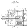
- One of the conventional compressors is shown in Fig. 15, which is generally designated by reference numeral 1A. As shown, the compressor 1A comprises a
swash plate 43 which is disposed about a drive shaft 11 to rotate therewith assuming an inclined position relative thereto. That is, for achieving such rotation of theswash plate 43, asleeve 61 with a pair ofpins 64 is slidably disposed on the drive shaft 11, and a hub portion of theswash plate 43 is pivotally connected to thepins 64. Acoil spring 80 is disposed about the drive shaft 11 to bias thesleeve 61 rightward in the drawing. - A plurality of
pistons 16 are incorporated withcorresponding cylinder bores 12a which are arranged at evenly spaced intervals about an axis of the drive shaft 11. Eachpiston 16 comprises ahead portion 17 which is slidably received in thecylinder bore 12a and astem portion 18 which is exposed to acrank chamber 13. Thestem portion 18 has a shoe holder portion which comprises two holding arms by which twosemi-spherical shoes shoes swash plate 43. Thus, when, due to rotation of the drive shaft, theswash plate 43 is rotated assuming a certain inclined position relative to the drive shaft 11, eachpiston 16 is forced to make reciprocating movement in thecorresponding cylinder bore 12a. Thus, a refrigerant vapor in thecylinder bore 12a is compressed. - A supporting
bracket 41 is secured at a base portion thereof to the drive shaft 11 to rotate therewith. The supportingbracket 41 has at a leading end adrive arm 42. A drivenarm 44 is secured to theswash plate 43. The drivenarm 44 has apin 46 secured thereto, which pin is slidably received in anelongate slot 45 formed in thedrive arm 42. Thus, a torque of the drive shaft 11 is transmitted to theswash plate 43 through the supportingbracket 41, thedrive arm 42, thepin 46 and the drivenarm 44. - Thus, during rotation together with the drive shaft 11, the
swash plate 43 can slide along the drive shaft 11 varying the inclination angle thereof relative to the drive shaft 11. - Designated by reference "Cv" is a pressure regulating valve which is installed in the compressor 1A. Due to operation of the valve "Cv", the pressure in the
crank chamber 13 is controlled, which varies the inclination angle of theswash plate 43 relative to the drive shaft 11 and thus varies the stroke of eachpiston 16 thereby regulating the displacement of the compressor 1A. - However, due to inherent construction, the above-mentioned conventional compressor 1A has the following drawbacks.
- (1) A so-called pivot pin type coupling
structure is employed for coupling the
swash plate 43 with the drive shaft 11, which includes thesleeve 61 and the twopins 64 secured to thesleeve 61. Due to employment of such type coupling structure (61, 64), the number of parts of the compressor 1A is increased, which induces an increase in production cost of the compressor 1A. - (2) Due to nature of such pivot pin type coupling structure, a play tends to occur in the structure, which causes generation of noises.
-
- The other of the conventional compressors is a compressor disclosed in Japanese Patent Second Provisional Publication 2-31234, which is partially shown in Figs. 16 and 17 as being designated by reference numeral 1B. In this conventional compressor 1B, there are no parts corresponding to the
sleeve 61 and thepins 64 of the above-mentioned compressor 1A of Fig. 15. That is, in the compressor 1B, a so-called pinless type coupling structure is employed in place of the pivot pin type coupling structure of Fig. 15. - As is shown in Figs. 16 and 17, in the coupling structure of the compressor 1B, a
center bore 54 is formed in a hub portion of theswash plate 53, through which the drive shaft 11 passes. As shown, thecenter bore 54 is so shaped as to permit an inclination of theswash plate 53 relative to the drive shaft 11. Fig. 16 shows a condition wherein theswash plate 53 is largely inclined relative to the drive shaft 11, while Fig. 17 shows a condition wherein theswash plate 53 is not inclined. - The
bore 54 comprises a front side borepart 54a and a rear side borepart 54b which are merged at animaginary crossing plane 71 which passes through inwardly projected portions (or ridges) 54c and 54d defined in thebore 54. When theswash plate 53 is inclined relative to the drive shaft 11, the projectedportions - However, even the compressor 1B having the above-mentioned pinless type coupling structure has the following drawbacks.
- (1) The
center bore 54 has a complicated form. Machining such complicated bore 54 in theswash plate 53 needs a very skilled and expensive technique, which thus causes increase in production cost of the compressor 1B. - (2) Due to the ridges (viz., inwardly
projected portions) 54c and 54d against which the
drive shaft 11 slidably abuts, marked abrasion
tends to occur at the
ridges ridges swash plate 53 and thus causes generation of noises in the compressor 1B. If the abrasion becomes much severe, smoothed pivoting of theswash plate 53 relative to the drive shaft 11 is not achieved. - (3) Due to nature of the pinless type
coupling structure, the
imaginary crossing plane 71 has an oval cross section. Thus, when theswash plate 53 assumes an intermediate position between the maximally inclined position of Fig. 16 and the non-inclined position of Fig. 17, a certain clearance is inevitably produced between the drive shaft 11 and each of the upper and lower ends of the inner wall of the center bore 54. Such clearance tends to promote the undesired play of theswash plate 53. -
- From prior
art documents DE 43 33 408 A1, EP-0 102 691 A1, and US 4,886,423 further variable displacement compressors of the swash plate type are known. Such compressors comprise a casing with cylinder bores being circumferentially arranged therein. Each cylinder bore receives a piston. A shaft is provided within said casing. Said shaft is provided with a spherical support portion. Said spherical support portion is received in a spherical surface portion of the swash plate so that said swash plate can be brought into several inclined positions with regard to said shaft. - Furthermore, a control and drive device is provided which is eccentrically connected with the swash plate for driving a connection therewith and controlling the inclined position of the swash plate. Thus, the torque transmission from the driving means to the swash plate is carried out by said device which is also used as a control means for said swash plate and basically no torque is transmitted via the spherical portions for supporting said swash plate.
- It is an objective of the present invention to provide a variable displacement swash plate type compressor which is low in costs and has a reliable coupling between a drive shaft and said swash plate of the compressor.
- According to the present invention this objective is solved by a variable displacement swash plate type compressor comprising: a casing having a plurality of cylinder bores circumferentially arranged therein; a plurality of pistons incorporated with the cylinder bores respectively; a drive shaft extending in said casing; a swash plate disposed about said drive shaft; a hinge mechanism for achieving a hinged connection between said drive shaft and said swash plate; means for making a hinged and slidable connection between the swash plate and each of the pistons to make a reciprocating movement of each piston when the swash plate is rotated together with said drive shaft; a coil spring disposed about said drive shaft for biasing said swash plate in a given direction; and a coupling structure arranged between said drive shaft and said swash plate in order to allow said swash plate to be movable along the drive shaft and inclinable relative to the same, said coupling structure including: a bearing portion provided on said drive shaft to rotate therewith, said bearing portion including first and second parts which are symmetrically arranged with respect to a longitudinal axis of said drive shaft, said first and second parts having respectively first and second outer walls which are substantially semi-cylindrical in shape and symmetrically arranged with respect to said longitudinal axis, each of said first and second parts further including first and second flat side walls which are symmetrically arranged with respect to the longitudinal axis, said first and second semi-cylindrical outer walls of the respective first and second parts of the bearing portion being perpendicular to the first and second flat side walls of the respective first and second parts; and means defining a center bore in a hub portion of said swash plate as to slidably receive therein said bearing portion, said center bore of said swash plate has a rectangular cross section with third and fourth flat walls which are slidably engaged with said first and second semi-cylindrical outer walls of the first and second part of the bearing portion respectively, and with third and fourth flat side walls which are slidably engaged with said first and second flat side walls of the first and second part of the bearing portion respectively.
- Preferred embodiments of the present invention are laid down in the dependent claims.
- Hereinafter the present invention is illustrated and explained by means of preferred embodiments in conjunction with the accompanying drawings. In the drawings wherein:
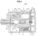
- Fig. 1 is a sectional view of a variable displacement swash plate type compressor which is a first embodiment;
- Fig. 2 is a partial and exploded view of a coupling structure employed in the compressor of the first embodiment;
- Fig. 3 is a sectional view taken along the line III-III of Fig. 2;
- Figs. 4 and 5 are views similar to Fig. 3, but showing modifications of the coupling structure of the first embodiment;
- Fig. 6 is a sectional view of a variable displacement swash plate type compressor which is a second embodiment;
- Fig. 7 is a partial and exploded view of a coupling structure employed in the compressor of the second embodiment;
- Fig. 8 is a sectional view taken along the line VIII-VIII of Fig. 7;
- Figs. 9 and 10 are views similar to fig. 8, but showing modifications of the coupling structure of the second embodiment;
- Fig. 11 is a sectional view of a variable displacement swash plate type compressor which is a third embodiment;
- Fig. 12 is a partial and exploded view of a coupling structure employed in the compressor of the third embodiment;
- Fig. 13 is a sectional view of a variable displacement type swash plate type compressor which is a fourth embodiment which does not fall under claim 1;
- Fig. 14 is a view similar to Fig. 13, but showing a different condition of the fourth embodiment;
- Fig. 15 is a sectional view of a conventional variable displacement swash plate type compressor; and
- Figs. 16 and 17 are partial sectional views of a coupling structure which is employed in another conventional variable displacement swash plate type compressor.
-
- Referring to Figs. 1 to 3, particularly Fig. 1, there is shown a variable displacement swash
plate type compressor 100A which is a first embodiment. - For ease of description, substantially the same parts as those of the above-mentioned conventional compressor 1A of Fig. 15 are designated by the same numerals and detailed explanation of them will be omitted from the following.
- As is seen from Fig. 1, the
compressor 100A comprises a drive shaft 11 which is installed in and rotatably supported by acylindrical casing 12. The drive shaft 11 is driven by an engine (not shown) through a known mechanism. Afront cover 14f is secured to a left open end of thecylindrical casing 12 and arear cover 14r is secured to a right open end of thecasing 12. With this, acrank chamber 13 is defined in thecylindrical casing 12, as shown. Therear cover 14r has adischarge chamber 26 formed therein, as shown. - Within the
crank chamber 13, there is installed aswash plate 15 which is disposed about the drive shaft 11 to rotate therewith. Within thecylindrical casing 12, there are formed a plurality of cylinder bores 12a which are arranged about an axis of the drive shaft 11 at evenly spaced intervals. Eachcylinder bore 12a has apiston 16 slidably received therein. Thepiston 16 comprises ahead portion 17 which is slidably received in thecylinder bore 12a and astem portion 18 which is exposed to the crankchamber 13. Thestem portion 18 has a shoe holding portion which comprises two holding arms by which twosemi-spherical shoes shoes peripheral part 15a of theswash plate 15. As shown, when the twosemi-spherical shoes - The shoe holding portion of the
stem portion 18 of eachpiston 16 has at a back side thereof arotation stopper portion 18a. Therotation stopper portion 18a is slidably engageable with aninner surface 12b of thecylindrical casing 12 to suppress a rotational movement of thepiston 16 about the axis of the same. - A supporting
bracket 21 is secured at a base portion thereof to the drive shaft 11 to rotate therewith. The supportingbracket 21 has at a leading end adrive arm 22. - As is seen in Fig. 2, two driven
arms 24 are secured to theswash plate 15. The drivenarms 24 have a hinge pin 25 (see Fig. 1) secured thereto, which pin is slidably received in anelongate slot 23 formed in thedrive arm 22. - With this, a so-called hinge mechanism "H" (see Fig. 1) is provided between the supporting
bracket 21 and theswash plate 15. That is, under rotation of the drive shaft 11, theswash plate 15 is rotated together with the drive shaft 11 and pivotal relative to the drive shaft 11 making thehinge pin 25 as a pivot center. - As shown in Fig. 1, between the
crank chamber 13 and anintake chamber 32 defined in therear cover 14r, there is defined a passage "R" in which a pressure regulating valve "Cv" of bellows type is arranged. Due to operation of the valve "Cv", the passage "R" is closed and opened. That is, in accordance with the pressure of a refrigerant vapor returned to theintake chamber 32, the bellows expands and contracts to close and open the passage "R" and thus controls the pressure in thecrank chamber 13. In accordance with the pressure in thecrank chamber 13, the inclination angle of theswash plate 15 relative to the drive shaft 11 is varied and thus the amount of compressed refrigerant vapor discharged from thecompressor 100A is controlled. - Denoted by
numeral 30 is an intake port and 31 is a discharge port which are incorporated with thecylinder bore 12a. Although not shown in the drawing, corresponding intake and discharge ports are provided for the remaining cylinder bores 12a. - In the following, features of the
first embodiment 100A will be described with reference to Figs. 1 to 3. - In Fig. 2, an improved coupling structure 100a employed in the
first embodiment 100A is shown. The coupling structure 100a comprises a drum-like bearing portion 40 integrally formed on the drive shaft 11. As will become apparent hereinafter, the drum-like bearing portion 40 is slidably received in a center bore 20 formed in theswash plate 15. The bearingportion 40 comprises twosemicylindrical parts semicylindrical parts - The center bore 20 of the
swash plate 15 has upper and lowerflat walls 20a to which cylindrical walls of the twosemicylindrical parts flat side walls 20b to which side walls of the twosemicylindrical parts recesses 20c in which side projections orside ridges 40c of the bearingportion 40 are loosely received. As is seen from Fig. 3, theside ridges 40c are diametrically opposed parts of the cylindrical wall of the drive shaft 11. A broaching technique may be used for providing theswash plate 15 with the center bore 20. - As is understood from Fig. 1, in assembly, the drum-
like bearing portion 40 is slidably received in the center bore 20 of theswash plate 15. That is, upon assembly, theswash plate 15 can move along the axis "X" of the drive shaft 11 while pivoting about bearingportion 40. - Because the bearing
portion 40 has a cylindrical outer surface, the pivoting movement of theswash plate 15 about the bearingportion 40 is smoothly made. - As is seen from Fig. 3, if desired, the axis "Y" may be positioned below the axis "X" by a given distance "S". With this distance "S", a vertical displacement of the
swash plate 15, which would inevitably occur when theswash plate 15 pivots about the bearingportion 40, is evenly carried out throughout the pivoting movement. - As is understood from Fig. 3, the diameter "D2" of the bearing
portion 40 is greater than the diameter "D1" of the drive shaft 11. The diameter "D2" of the bearingportion 40 is so determined as to assure the slidable contact with the upper and lowerflat walls 20a of the center bore 20 of theswash plate 15 irrespective of any inclined position which theswash plate 15 assumes. - As will be understood from Fig. 2, the upper and lower flat paired
side walls 20b of the center bore 20 of theswash plate 15 make a so-called "large surface contact" with the side walls of the bearingportion 40. Thus, a play of theswash plate 15 about a vertical axis "Z" is assuredly suppressed. This means that the hinge mechanism "H" (see Fig. 1) has no need of providing any function to suppress such play. That is, the hinge mechanism "H" employed in thefirst embodiment 100A can have a simple construction. - In this embodiment, the torque transmission from the drive shaft 11 to the
swash plate 15 is carried out through two independent paths, one being through the hinge mechanism "H" and the other being through the bearingportion 40. Thus, the torque transmission is reliably carried out. - Figs. 4 and 5 show modifications 40M1 and 40M2 of the bearing
portion 40. In the modification 40M1 of Fig. 4, the outer cylindrical wall has a radius of curvature in the direction of the axis "Y". That is, the bearing portion 40M1 has a spherical outer surface. In the modification 40M2 of Fig. 5, a separate bearing member 40' is employed, which is tightly disposed on the drive shaft 11. - In the following, operation of the above-mentioned
compressor 100A of the first embodiment will be outlined with reference to Fig. 1. - When, for operating a cooling section of an automotive air conditioning system, the drive shaft 11 is driven by the engine, the
swash plate 15 is rotated together with the drive shaft 11 while assuming a certain inclined position relative to the drive shaft 11. Due to the turns of theswash plate 15, eachpiston 16 is forced to make reciprocating movement in thecorresponding cylinder bore 12a, and thus, the refrigerant vapor from an evaporator (not shown) is sucked into the cylinder bores 12a through theintake chamber 32 and theintake ports 30. After being compressed by thepistons 16 in the cylinder bores 12a, the compressed refrigerant vapor is discharged to thedischarge chamber 26 through thedischarge ports 31. The compressed refrigerant vapor in thedischarge chamber 26 is then supplied to a condenser (not shown) to be condensed. - Under a severe cooling load, it is necessary to compress a larger amount of refrigerant vapor. In this case, the pressure of the refrigerant vapor led to the
intake chamber 32 is relatively high and thus the pressure in the passage "R" is high. Under this condition, the bellows of the pressure regulating valve "Cv" is contracted and thus opens the passage "R". As a result, the pressure in thecrank chamber 13 becomes equal to that in theintake chamber 32. In other words, the pressure in thecrank chamber 13 is lowered. - During operation of the
compressor 100A, the pressure in thecrank chamber 13 applies to a left end (as viewed in Fig. 1) of eachpiston 16 and the pressure in a compression chamber of thecorresponding cylinder bore 12a applies to a right end of thepiston 16. Thus, eachpiston 16 is pressed toward a lower pressure side with a force corresponding to the pressure difference therebetween. The forces applied to all thepistons 16 are added to determine the inclination angle of theswash plate 15. - When, as is described hereinabove, the pressure in the
crank chamber 13 becomes lowered, the force for pressing eachpiston 16 leftward in Fig. 1, that is, toward theswash plate 15 is increased. That is, theswash plate 15 is biased leftward. However, due to provision and function of the hinge mechanism "H", the biasing force thus applied to theswash plate 15 causes the same to be inclined largely about the axis of thepin 25. Under this condition, eachpiston 16 is forced to have a long stroke, and thus, the displacement of thecompressor 100A is increased. - Under a lower cooling load, it is only necessary to compress a smaller amount of refrigerant vapor. In this case, the pressure of the refrigerant vapor led to the
intake chamber 32 is relatively low, and thus, the pressure in the passage "R" is low. Under this condition, the bellows of the pressure regulating valve "Cv" is expanded and thus closes the passage "R". As a result, the pressure in thecrank chamber 13 becomes isolated from theintake chamber 32. In this state, the pressure in thecrank chamber 13 is gradually increased due to penetration of high pressure vapor thereinto through a clearance between each piston 1 and thecorresponding cylinder bore 12a. - When the pressure in the
crank chamber 13 is increased and the pressure becomes higher than that in the compression chamber of eachcylinder bore 12a, the force for pressing each piston leftward, that is, toward theswash plate 15 is lowered. Accordingly, due to the force of acoil spring 80, theswash plate 15 is moved rightward reducing the inclination angle thereof relative to the drive shaft 11. Under this condition, eachpiston 16 is forced to have a short stroke, and thus, the displacement of thecompressor 100A is lowered. - In the following, advantages of the
first embodiment 100A will be described. - (1) As is described hereinabove, the sliding
movement of the
swash plate 15 along the drive shaft 11 as well as the pivoting movement of theswash plate 15 relative to the drive shaft 11 are smoothly achieved with the coupling structure 100a which has a simple structure. In fact, such coupling structure 100a has no parts corresponding to thesleeve 61 and the twopins 64 employed in the conventional compressor 1A of Fig. 15. Thus, production cost can be reduced in the invention. - (2) The center bore 20 of the
swash plate 15 makes a so-called "large surface contact" with the drum-like bearing portion 40 of the drive shaft. Thus, undesired play of theswash plate 15 relative to the drive shaft 11 is assuredly suppressed. Furthermore, bearing stress applied to the contact surface is lowered and thus undesired abrasion of the mutually contacting parts is minimized. - (3) The torque transmission from the drive
shaft 11 to the
swash plate 15 is carried out through two independent transmission paths, one being through the hinge mechanism "H" and the other being through the bearingportion 40. Thus, the torque transmission is assuredly achieved. -
- Referring to Figs. 6 to 8, particularly Fig. 6, there is shown a variable displacement swash
plate type compressor 100B which is a second embodiment. - Since this
second embodiment 100B is similar to the above-mentionedfirst embodiment 100A, only portions and parts which are different from those of thefirst embodiment 100A will be described for ease of description. - That is, as is seen from Fig. 7, a
coupling structure 100b employed in thesecond embodiment 100B differs from that of thefirst embodiment 100A. As will become apparent hereinafter, in thecoupling structure 100b of thesecond embodiment 100B, a measure is employed for assuring engagement between thecoil spring 80 and theswash plate 15 even when theswash plate 15 assumes the non-inclined position. - As is shown in Fig. 7, the bearing
portion 40 is formed with arectangular recess 40d which faces toward the coil spring 80 (see Fig. 6) and accommodates a part of the drive shaft 11. The bearingportion 40 has no portions corresponding to theside ridges 40c (see Fig. 2) of the first embodiment. That is, in thesecond embodiment 100B, the thickness of the bearingportion 40 is equal to the diameter of the drive shaft 11, as is well seen from Fig. 8. - As is understood from Fig. 6, the
rectangular recess 40d is so sized as to freely receive thecoil spring 80 when the latter expands toward the bearingportion 40. - The center bore 20 of the
swash plate 15 has a rectangular cross section, which is thus defined by upper and lowerflat walls 20a and twoside walls 20b. Asemicircular recess 20d is formed on the hub portion of theswash plate 15 for receiving one end of thecoil spring 80. - As is seen from Fig. 8, similar to the case of the first embodiment (see Fig. 3), the axis "Y" may be positioned below the axis "X" by a given distance "S".
- Due to provision of the
recess 40d, abutment of thecoil spring 80 with the bearingportion 40 is suppressed, which assures an operational abutment of thecoil spring 80 with the hub portion of theswash plate 15. - Figs. 9 and 10 show modifications 40M3 and 40M4 of the bearing
portion 40. In the modification 40M3 of Fig. 9, the outer cylindrical wall has a radius of curvature in the direction of the axis "Y". That is, the bearing portion 40M3 has a spherical outer surface. In the modification 40M4 of Fig. 10, a separate bearing member 40' is employed, which is tightly disposed on the drive shaft 11. - It is easily understood that the advantages of the
first embodiment 100A are equally possessed by thesecond embodiment 100B. - Referring to Figs. 11 and 12, particularly Fig. 11, there is shown a variable displacement swash plate type compressor 100C which is a third embodiment.
- Since this third embodiment 100C is similar to the above-mentioned
second embodiment 100B, only portions and parts which are different from those of thesecond embodiment 100B will be described for ease of description. - That is, a hinge mechanism H' employed in the third embodiment differs from that of the
second embodiment 100B. - As is seen from Fig. 11, the hinge mechanism H' comprises a
cylindrical bore 27 formed in thedrive arm 22 of the supportingbracket 21. Movably and slidably received in thebore 27 is aspherical head 28b (see Fig. 12) of aguide pin 28. Ashaft portion 28a of theguide pin 28 is secured to the hub portion of theswash plate 15. More specifically, as shown in Fig. 12, a base part of theshaft portion 28a is tightly pressed into anapertured stub portion 29 which is formed on the hub portion of theswash plate 15. Of course, theshaft portion 28a may be screwed into a threaded aperture formed in thestub portion 29. - In the third embodiment 100C, the hinge mechanism H' employs a so-called ball-and-socket universal joint. It is to be noted that such hinge mechanism H' is used only in a case wherein, like in the above-mentioned first and
second embodiments swash plate 15 can be made by only thecoupling structure 100a or 100b. - Due to the similar construction, the advantages of the
second embodiment 100B are equally possessed by the third embodiment 100C. - Referring to Figs. 13 and 14, there is shown a variable displacement swash
plate type compressor 100D which is a fourth embodiment which does not fall under claim 1 but represents background art for understanding the invention. - Since this
fourth embodiment 100D is similar to the above-mentionedsecond embodiment 100B, only portions and parts which are different from those of thesecond embodiment 100B will be described. - That is, a coupling structure 100d employed in this
fourth embodiment 100D is somewhat different from that of thesecond embodiment 100B. In thisfourth embodiment 100D, acam member 70 is integrally formed on the drive shaft 11, which comprises a shorter arm 70a and alonger arm 70b. The shorter andlonger arms 70a and 70b are arranged to define therebetween a given clearance for suppressing engagement with thecoil spring 80 irrespective of any inclined position which theswash plate 15 assumes. The arms 70a are 70b have respective cam surfaces which are slidably engaged with the upper and lowerflat walls 20a of the center bore 20 of theswash plate 15. It is to be noted that the arm 70a which is closer to the hinge mechanism "H" than thearm 70b has a shorter length. - Due to the similar construction, the advantages of the
second embodiment 100B are equally possessed by thefourth embodiment 100D. More specifically, in thefourth embodiment 100D, the production cost can be more reduced due to the quite simple construction of the coupling structure 100d.
Claims (12)
- A variable displacement swash plate type compressor comprising:a casing (12) having a plurality of cylinder bores (12a) circumferentially arranged therein;a plurality of pistons (16) incorporated with the cylinder bores (12a) respectively;a drive shaft (11) extending in said casing (12);a swash plate (15) disposed about said drive shaft (11);a hinge mechanism (H, H') for achieving a hinged connection between said drive shaft (11) and said swash plate (15);means for making a hinged and slidable connection between the swash plate (15) and each of the pistons (16) to make a reciprocating movement of each piston (16) when the swash plate (15) is rotated together with said drive shaft (11);a coil spring (80) disposed about said drive shaft (11) for biasing said swash plate (15) in a given direction; anda coupling structure arranged between said drive shaft (11) and said swash plate (15) in order to allow said swash plate (15) to be movable along the drive shaft (11) and inclinable relative to the same, said coupling structure including:
a bearing portion (40) provided on said drive shaft (11) to rotate therewith, said bearing portion (40) including first and second parts (40a, 40b) which are symmetrically arranged with respect to a longitudinal axis (X) of said drive shaft (11), said first and second parts (40a, 40b) having respectively first and second outer walls which are substantially semi-cylindrical in shape and symmetrically arranged with respect to said longitudinal axis (X) constituting substantially the cyclindrical wall of an imaginary right cylinder, each of said first and second parts (40a, 40b) further including first and second flat side walls which are symmetrically arranged with respect to the longitudinal axis (X), said first and second semi-cylindrical outer walls of the respective first and second parts (40a, 40b) of the bearing portion (40) being perpendicular to the first and second flat side walls of the respective first and second parts (40a, 40b); andmeans defining a center bore (20) in a hub portion of said swash plate (15) as to slidably receive therein said bearing portion (40), said center bore (20) of said swash plate (15) has a rectangular cross section with third and fourth flat walls (20a) which are slidably engaged with said first and second semi-cylindrical outer walls of the first and second part (40a, 40b) of the bearing portion respectively, and with third and fourth flat side walls (20b) which are slidably engaged with said first and second flat side walls of the first and second part (40a, 40b) of the bearing portion respectively. - A variable displacement swash plate type compressor according to claim 1, wherein said first and second semi-cylindrical outer walls of said bearing portion has a common axis is in parallel with a hinge axis defined by said hinge mechanism (H).
- A variable displacement swash plate type compressor according to claim 2, wherein an axis of said imaginary right cylinder and the longitudinal axis (X) of said drive shaft (11) intersect at right angles.
- A variable displacement swash plate type compressor according to claim 2, wherein an axis of said imaginary right cylinder is perpendicular to the longitudinal axis (X) of said drive shaft (11) and separated from the same.
- A variable displacement swash plate type compressor according to one of the claims 1 to 4, wherein said bearing portion (40) is integral with said drive shaft (11).
- A variable displacement swash plate type compressor according to one of the claims 1 to 4, wherein said bearing portion (40) is a separate member which is tightly disposed on said drive shaft (11).
- A variable displacement swash plate type compressor according to one of the claims 1 to 6, wherein each of said first and second semi-cylindrical outer walls of said bearing portion (40) has a spherical surface.
- A variable displacement swash plate type compressor according to one of the claims 1 to 7, wherein said bearing portion (40) is formed with a recess (40d) for suppressing engagement with said coil spring (80) irrespective of any inclined position which said swash plate (15) assumes.
- A variable displacement swash plate type compressor according to claim 8, wherein said recess (40d) is rectangular in shape and faces toward said coil spring (80).
- A variable displacement swash plate type compressor according to claim 8 or 9, wherein the hub portion of said swash plate (15) is formed with a semicircular recess (20d) for seating therein one end of said coil spring (80).
- A variable displacement swash plate type compressor according to one of the claims 1 to 7, wherein said bearing portion (40) further includes first and second side ridges (40c) which are symmetrically arranged with respect to the longitudinal axis (X) of said drive shaft (11) and extend on the first and second flat side walls of said bearing portion (40), and said center bore (20) is further defined by third and fourth recesses (20c) in said first and second side ridges (40c) are loosely received.
- A variable displacement swash plate type compressor according to claim 11, wherein said first and second side ridges (40c) constitute diametrically opposed portions of said drive shaft (11).
Applications Claiming Priority (6)
| Application Number | Priority Date | Filing Date | Title |
|---|---|---|---|
| JP23708795 | 1995-09-14 | ||
| JP23708795 | 1995-09-14 | ||
| JP237087/95 | 1995-09-14 | ||
| JP307748/95 | 1995-11-27 | ||
| JP30774895 | 1995-11-27 | ||
| JP7307748A JPH09137775A (en) | 1995-09-14 | 1995-11-27 | Variable capacity swash plate compressor |
Publications (2)
| Publication Number | Publication Date |
|---|---|
| EP0773366A1 EP0773366A1 (en) | 1997-05-14 |
| EP0773366B1 true EP0773366B1 (en) | 2002-05-22 |
Family
ID=26533035
Family Applications (1)
| Application Number | Title | Priority Date | Filing Date |
|---|---|---|---|
| EP96114751A Expired - Lifetime EP0773366B1 (en) | 1995-09-14 | 1996-09-13 | Variable displacement swash plate type compressor |
Country Status (4)
| Country | Link |
|---|---|
| US (1) | US5749712A (en) |
| EP (1) | EP0773366B1 (en) |
| JP (1) | JPH09137775A (en) |
| DE (1) | DE69621308T2 (en) |
Families Citing this family (18)
| Publication number | Priority date | Publication date | Assignee | Title |
|---|---|---|---|---|
| JP3826473B2 (en) * | 1997-02-28 | 2006-09-27 | 株式会社豊田自動織機 | Variable capacity compressor |
| JPH10266952A (en) * | 1997-03-25 | 1998-10-06 | Zexel Corp | Variable displacement swash plate compressor |
| JP3860311B2 (en) * | 1997-10-21 | 2006-12-20 | カルソニックカンセイ株式会社 | Swash plate compressor |
| JP3880158B2 (en) | 1997-10-21 | 2007-02-14 | カルソニックカンセイ株式会社 | Swash plate compressor |
| JPH11125176A (en) * | 1997-10-21 | 1999-05-11 | Calsonic Corp | Swash plate type variable displacement compressor |
| JP3880160B2 (en) | 1997-10-21 | 2007-02-14 | カルソニックカンセイ株式会社 | Swash plate type variable capacity compressor |
| JP3880159B2 (en) | 1997-10-21 | 2007-02-14 | カルソニックカンセイ株式会社 | Swash plate type variable capacity compressor |
| JPH11125177A (en) * | 1997-10-21 | 1999-05-11 | Calsonic Corp | Swash plate type variable displacement compressor |
| JPH11193781A (en) * | 1997-12-26 | 1999-07-21 | Toyota Autom Loom Works Ltd | Variable displacement compressor |
| JPH11280645A (en) * | 1998-03-27 | 1999-10-15 | Sanden Corp | Variable capacity swash plate compressor |
| US6139283A (en) * | 1998-11-10 | 2000-10-31 | Visteon Global Technologies, Inc. | Variable capacity swash plate type compressor |
| JP3479233B2 (en) * | 1999-03-11 | 2003-12-15 | サンデン株式会社 | Cam mechanism of variable capacity swash plate type compressor |
| US6354809B1 (en) * | 2000-01-27 | 2002-03-12 | Ford Global Technologies, Inc. | Variable swash plate compressor |
| WO2005035981A1 (en) * | 2003-10-14 | 2005-04-21 | Valeo Thermal Systems Japan Corporation | Swash plate-type compressor |
| JP2007113504A (en) * | 2005-10-21 | 2007-05-10 | Sanden Corp | Variable displacement swash-plate type compressor |
| US7455009B2 (en) * | 2006-06-09 | 2008-11-25 | Visteon Global Technologies, Inc. | Hinge for a variable displacement compressor |
| JP6171875B2 (en) * | 2013-11-13 | 2017-08-02 | 株式会社豊田自動織機 | Variable capacity swash plate compressor |
| US9765764B2 (en) * | 2014-04-07 | 2017-09-19 | Hanon Systems | Hinge mechanism for a variable displacement compressor |
Family Cites Families (12)
| Publication number | Priority date | Publication date | Assignee | Title |
|---|---|---|---|---|
| US4433596A (en) * | 1980-03-11 | 1984-02-28 | Joseph Scalzo | Wabbler plate engine mechanisms |
| US4475871A (en) * | 1982-08-02 | 1984-10-09 | Borg-Warner Corporation | Variable displacement compressor |
| US4506648A (en) * | 1982-11-01 | 1985-03-26 | Borg-Warner Corporation | Controlled displacement supercharger |
| US4688439A (en) * | 1984-04-17 | 1987-08-25 | S. V. Engine Co. Pty. Ltd. | Wabble plate engine mechansim |
| US4712982A (en) * | 1985-03-25 | 1987-12-15 | Kabushiki Kaisha Toyoda Jidoshokki Seisakusho | Variable displacement wobble plate type compressor with guide means for wobble plate |
| JPS6287678A (en) * | 1985-10-11 | 1987-04-22 | Sanden Corp | Swash plate type variable displacement compressor |
| CA1237294A (en) * | 1986-03-27 | 1988-05-31 | Joseph Scalzo | Wobble plate engine stabiliser mechanism |
| US4886423A (en) * | 1986-09-02 | 1989-12-12 | Nippon Soken, Inc. | Variable displacement swash-plate type compressor |
| ATE58416T1 (en) * | 1987-08-06 | 1990-11-15 | Michel Drevet | ROTATING DRUM PISTON MACHINE WITH FIXED, CENTERING BELLY JOINT. |
| US5364232A (en) * | 1992-03-03 | 1994-11-15 | Kabushiki Kaisha Toyoda Jidoshokki Seisakusho | Variable displacement compressor |
| JP3049965B2 (en) * | 1992-10-01 | 2000-06-05 | 株式会社豊田自動織機製作所 | Variable capacity swash plate compressor |
| JP2575595B2 (en) * | 1992-10-20 | 1997-01-29 | インターナショナル・ビジネス・マシーンズ・コーポレイション | Image frame compression method and data processing system |
-
1995
- 1995-11-27 JP JP7307748A patent/JPH09137775A/en not_active Withdrawn
-
1996
- 1996-09-13 DE DE69621308T patent/DE69621308T2/en not_active Expired - Fee Related
- 1996-09-13 EP EP96114751A patent/EP0773366B1/en not_active Expired - Lifetime
- 1996-09-13 US US08/712,604 patent/US5749712A/en not_active Expired - Fee Related
Also Published As
| Publication number | Publication date |
|---|---|
| DE69621308D1 (en) | 2002-06-27 |
| EP0773366A1 (en) | 1997-05-14 |
| US5749712A (en) | 1998-05-12 |
| JPH09137775A (en) | 1997-05-27 |
| DE69621308T2 (en) | 2002-09-05 |
Similar Documents
| Publication | Publication Date | Title |
|---|---|---|
| US5749712A (en) | Variable displacement swash plate type compressor | |
| JP3125952B2 (en) | Variable capacity swash plate compressor | |
| US6139283A (en) | Variable capacity swash plate type compressor | |
| US8152483B2 (en) | Variable capacity compressor | |
| US5615599A (en) | Guiding mechanism for reciprocating piston of piston-type compressor | |
| JPH08326655A (en) | Swash plate type compressor | |
| US5644968A (en) | Variable capacity swash plate type compressor with an improved hinge unit for inclinably supporting a swash plate | |
| US6742439B2 (en) | Variable displacement compressor | |
| EP0867617B1 (en) | Variable capacity swash plate compressor | |
| EP0809024A1 (en) | Reciprocating pistons of piston type compressor | |
| US6786705B2 (en) | Variable displacement compressor | |
| JP2001304102A (en) | Variable capacity compressor | |
| US5364232A (en) | Variable displacement compressor | |
| JP2917767B2 (en) | Variable capacity swash plate compressor | |
| US6546841B2 (en) | Swash plate compressor and piston therefor | |
| US20040055456A1 (en) | Variable displacement compressor | |
| JP4506031B2 (en) | Variable capacity compressor | |
| US6474955B1 (en) | Hinge mechanism for variable displacement compressors | |
| US5517900A (en) | Tiltable swash plate type compressor | |
| US5882179A (en) | Compressor with bearing between the drive shaft and the swash-plate boss | |
| US6293761B1 (en) | Variable displacement swash plate type compressor having pivot pin | |
| EP1531266B1 (en) | Variable displacement compressor | |
| JP3183461B2 (en) | Assembling method of variable capacity swash plate type compressor | |
| JPH08312528A (en) | Swash plate type variable displacement compressor | |
| JP3437595B2 (en) | Variable capacity swash plate type hydraulic rotary machine |
Legal Events
| Date | Code | Title | Description |
|---|---|---|---|
| PUAI | Public reference made under article 153(3) epc to a published international application that has entered the european phase |
Free format text: ORIGINAL CODE: 0009012 |
|
| 17P | Request for examination filed |
Effective date: 19960913 |
|
| AK | Designated contracting states |
Kind code of ref document: A1 Designated state(s): DE FR GB IT SE |
|
| 17Q | First examination report despatched |
Effective date: 19991118 |
|
| RAP1 | Party data changed (applicant data changed or rights of an application transferred) |
Owner name: CALSONIC KANSEI CORPORATION |
|
| GRAG | Despatch of communication of intention to grant |
Free format text: ORIGINAL CODE: EPIDOS AGRA |
|
| GRAG | Despatch of communication of intention to grant |
Free format text: ORIGINAL CODE: EPIDOS AGRA |
|
| GRAH | Despatch of communication of intention to grant a patent |
Free format text: ORIGINAL CODE: EPIDOS IGRA |
|
| GRAH | Despatch of communication of intention to grant a patent |
Free format text: ORIGINAL CODE: EPIDOS IGRA |
|
| GRAA | (expected) grant |
Free format text: ORIGINAL CODE: 0009210 |
|
| PG25 | Lapsed in a contracting state [announced via postgrant information from national office to epo] |
Ref country code: IT Free format text: LAPSE BECAUSE OF FAILURE TO SUBMIT A TRANSLATION OF THE DESCRIPTION OR TO PAY THE FEE WITHIN THE PRE;WARNING: LAPSES OF ITALIAN PATENTS WITH EFFECTIVE DATE BEFORE 2007 MAY HAVE OCCURRED AT ANY TIME BEFORE 2007. THE CORRECT EFFECTIVE DATE MAY BE DIFFERENT FROM THE ONE RECORDED.SCRIBED TIME-LIMIT Effective date: 20020522 Ref country code: FR Free format text: LAPSE BECAUSE OF FAILURE TO SUBMIT A TRANSLATION OF THE DESCRIPTION OR TO PAY THE FEE WITHIN THE PRESCRIBED TIME-LIMIT Effective date: 20020522 |
|
| REG | Reference to a national code |
Ref country code: GB Ref legal event code: FG4D |
|
| REF | Corresponds to: |
Ref document number: 69621308 Country of ref document: DE Date of ref document: 20020627 |
|
| PG25 | Lapsed in a contracting state [announced via postgrant information from national office to epo] |
Ref country code: SE Free format text: LAPSE BECAUSE OF FAILURE TO SUBMIT A TRANSLATION OF THE DESCRIPTION OR TO PAY THE FEE WITHIN THE PRESCRIBED TIME-LIMIT Effective date: 20020822 |
|
| PG25 | Lapsed in a contracting state [announced via postgrant information from national office to epo] |
Ref country code: GB Free format text: LAPSE BECAUSE OF NON-PAYMENT OF DUE FEES Effective date: 20020913 |
|
| EN | Fr: translation not filed | ||
| PLBE | No opposition filed within time limit |
Free format text: ORIGINAL CODE: 0009261 |
|
| STAA | Information on the status of an ep patent application or granted ep patent |
Free format text: STATUS: NO OPPOSITION FILED WITHIN TIME LIMIT |
|
| PG25 | Lapsed in a contracting state [announced via postgrant information from national office to epo] |
Ref country code: DE Free format text: LAPSE BECAUSE OF NON-PAYMENT OF DUE FEES Effective date: 20030401 |
|
| GBPC | Gb: european patent ceased through non-payment of renewal fee |
Effective date: 20020913 |
|
| 26N | No opposition filed |
Effective date: 20030225 |