EP0773304B1 - Wear resisting sintered alloy and control rod driving apparatus of a nuclear reactor using it - Google Patents
Wear resisting sintered alloy and control rod driving apparatus of a nuclear reactor using it Download PDFInfo
- Publication number
- EP0773304B1 EP0773304B1 EP96308067A EP96308067A EP0773304B1 EP 0773304 B1 EP0773304 B1 EP 0773304B1 EP 96308067 A EP96308067 A EP 96308067A EP 96308067 A EP96308067 A EP 96308067A EP 0773304 B1 EP0773304 B1 EP 0773304B1
- Authority
- EP
- European Patent Office
- Prior art keywords
- wear
- range
- control rod
- roller
- alloy
- Prior art date
- Legal status (The legal status is an assumption and is not a legal conclusion. Google has not performed a legal analysis and makes no representation as to the accuracy of the status listed.)
- Expired - Lifetime
Links
Images


Classifications
-
- G—PHYSICS
- G21—NUCLEAR PHYSICS; NUCLEAR ENGINEERING
- G21C—NUCLEAR REACTORS
- G21C7/00—Control of nuclear reaction
- G21C7/06—Control of nuclear reaction by application of neutron-absorbing material, i.e. material with absorption cross-section very much in excess of reflection cross-section
- G21C7/08—Control of nuclear reaction by application of neutron-absorbing material, i.e. material with absorption cross-section very much in excess of reflection cross-section by displacement of solid control elements, e.g. control rods
- G21C7/10—Construction of control elements
- G21C7/113—Control elements made of flat elements; Control elements having cruciform cross-section
-
- C—CHEMISTRY; METALLURGY
- C22—METALLURGY; FERROUS OR NON-FERROUS ALLOYS; TREATMENT OF ALLOYS OR NON-FERROUS METALS
- C22C—ALLOYS
- C22C1/00—Making non-ferrous alloys
- C22C1/04—Making non-ferrous alloys by powder metallurgy
- C22C1/05—Mixtures of metal powder with non-metallic powder
- C22C1/059—Making alloys comprising less than 5% by weight of dispersed reinforcing phases
-
- C—CHEMISTRY; METALLURGY
- C22—METALLURGY; FERROUS OR NON-FERROUS ALLOYS; TREATMENT OF ALLOYS OR NON-FERROUS METALS
- C22C—ALLOYS
- C22C32/00—Non-ferrous alloys containing at least 5% by weight but less than 50% by weight of oxides, carbides, borides, nitrides, silicides or other metal compounds, e.g. oxynitrides, sulfides, whether added as such or formed in situ
- C22C32/0047—Non-ferrous alloys containing at least 5% by weight but less than 50% by weight of oxides, carbides, borides, nitrides, silicides or other metal compounds, e.g. oxynitrides, sulfides, whether added as such or formed in situ with carbides, nitrides, borides or silicides as the main non-metallic constituents
-
- Y—GENERAL TAGGING OF NEW TECHNOLOGICAL DEVELOPMENTS; GENERAL TAGGING OF CROSS-SECTIONAL TECHNOLOGIES SPANNING OVER SEVERAL SECTIONS OF THE IPC; TECHNICAL SUBJECTS COVERED BY FORMER USPC CROSS-REFERENCE ART COLLECTIONS [XRACs] AND DIGESTS
- Y02—TECHNOLOGIES OR APPLICATIONS FOR MITIGATION OR ADAPTATION AGAINST CLIMATE CHANGE
- Y02E—REDUCTION OF GREENHOUSE GAS [GHG] EMISSIONS, RELATED TO ENERGY GENERATION, TRANSMISSION OR DISTRIBUTION
- Y02E30/00—Energy generation of nuclear origin
- Y02E30/30—Nuclear fission reactors
Definitions
- the present invention relates to a wear resisting sintered alloy having excellent wear resistance, corrosion resistance and impact resistance, and particularly to a wear resisting alloy suitable for sliding members used in a control rod driving apparatus of a nuclear reactor plant.
- Cobalt-based alloys have been used for sliding members of a nuclear reactor plant. Specifically, a cobalt alloy called “stellite” has been applied to guide rollers or bushes for a control rod. This cobalt alloy contains 28-30 wt% of Cr, 2-2.5 wt% of C, and small amounts of W, Fe and Ni, the balance being Co. This alloy is excellent in corrosion resistance because of the high content of Cr, and also it is high in hardness because of the high content of C, leading to an excellent wear resistance.
- a member made of such an alloy presents a disadvantage when placed in a reactor water at a high temperature and a high pressure. Namely, in this case, cobalt is eluted in the reactor water; the eluted cobalt adheres on the surface of a fuel sheath tube and is radio-activated; and the radio-activated cobalt is eluted again and circulated in the reactor water. As a result, the exposure dose is increased upon periodic inspection or repair for the plant, to extend a shutdown period, thus reducing the availability factor of the plant.
- Japanese Patent Publication No. Sho 59-52228 has already disclosed a sliding material not containing cobalt as a main component.
- a nickel-based alloy is used as a roller material; however, since the alloy has a wear resistance lower than that of a cobalt-based alloy, it causes a large dimensional change due to wear and is poor in long-term service when used as a roller material for a sliding portion applied with a high mechanical load.
- Japanese Patent Publication No. Sho 58-23454 has disclosed a nickel-based alloy containing Cr and Nb; however, it is poor in impact value and thereby low in reliability when applied with an impact load at the time of scram.
- WO-A-92/11941 describes a sintered material for wear applications. It comprises an iron-based alloy, which forms a soft matrix of 250-800 HV, in which grains of hard materials of at least 1000 Hv are dispersed.
- An object of the present invention is to provide a wear resisting alloy which can be superior in wear resistance to stellite, high in reliability for an impact load due to high speed driving at the time of scram, and low in exposure dose by elimination of elution of cobalt, thereby ensuring the smooth driving of a reactor control rod using the alloy in high temperature water and at a high load for a long time.
- a further object of the present invention is to provide a control rod driving apparatus and a nuclear reactor using the above alloy.
- the present invention provides a wear resisting sintered alloy as set out in claim 1.
- the present invention also provides a control rod driving apparatus as set out in claim 5 including a housing, a hollow piston provided in said housing, a driving piston for vertically driving said hollow piston, rollers provided on a tube between said hollow piston and the tube provided in said housing, and pins functioning as rotating shafts of said rollers, wherein each of said rollers is made of a sintered alloy of the invention.
- each of the pin and the roller is made of an iron-based or a nickel-based alloy having a wear characteristic such that the total wear amount of said roller and said pin is within a range of 10 mg or less per unit area (sliding width 7.5 mm ⁇ sliding distance 1 km) in a wear test performed under a load of 1 kg per sliding width of 0. 75 mm in water at a temperature of 288°C.
- the roller may be made of an iron-based or a nickel-based alloy having a wear characteristic such that the wear amount of said roller is within a range of 8.5 mg or less per unit area (sliding width 7.5 mm ⁇ sliding distance 1 km) in a wear test relative to said pin performed under a load of 1 kg per sliding width of 0.75 mm in water at a temperature of 288°C.
- the pin may be made of an iron-based or a nickel-based alloy having a wear characteristic such that the wear amount of said pin is within a range of 4.5 mg or less per unit area (sliding width 7.5 mm ⁇ sliding distance 1 km) in a wear test relative to said roller performed under a load of 1 kg per sliding width of 0.75 mm in water at a temperature of 288°C.
- the present invention also provides a nuclear reactor as set out in claim 9.
- the present invention also provides a roller for a control rod driving apparatus, which is made of a wear resisting sintered alloy of the invention.
- the present invention also provides a method of producing a wear resisting sintered alloy as set out in claim 11.
- a control rod driving apparatus of a nuclear plant is being changed from the conventional hydraulic driving type to a motor-driven type enabling fine adjustment.
- the new type control rod driving apparatus uses guide rollers for making smooth the movement of a hollow piston.
- the guide roller is applied with a load very larger than that applied to the guide roller used for the related art control rod, and thereby it requires a higher wear resistance.
- this roller there occurs wear mainly on the inner peripheral surface of the roller and on the outer surface of a fixed pin for supporting the roller. More specifically, since the roller is slid on the pin in high temperature water without any lubrication, there occurs adhesive wear due to relative sliding movement between the roller and the pin. In the adhesive wear, a shearing stress produced at the contact portion due to adhesion forms a plastic flow layer near the sliding surface. By repeated sliding, part of the plastic flow layer is finally broken and separated into a wear powder. Accordingly, to reduce a damage due to adhesive wear, it is necessary to impart a specified level or more of hardness or strength to the alloy for suppressing the plastic deformation at the contact portion.
- a sliding member is made of an alloy in which a hard phase is precipitated or dispersed in a matrix for reinforcement of the strength by adjustment of a chemical composition of the alloy.
- the hard phase in the related art material is effective in terms of suppressing plastic deformation of the sliding surface and improving the wear resistance; however, it is not effective in terms of suppressing the most essential adhesion for the wear resistance.
- the size of particles forming the hard phase of the related art material is relatively small, so that the surfaces of the particles forming the hard phase are easily covered with the metal forming abasic phase due to plastic flow. This exerts adverse effect on suppression of adhesion.
- a guide roller in a control rod driving mechanism is used in high temperature water for a long time, a material used for the guide roller is additionally required to be excellent in corrosion resistance.
- an important feature of the present invention lies in that particles of a hard phase, having a particle size sufficiently large not to be perfectly covered by plastic flow, are suitably dispersed in a relatively soft matrix. These coarse particles of the hard phase not only suppress plastic flow, but prevent adhesion because they are exposed from the wear surface and thereby not perfectly covered with the soft matrix by plastic flow. Another reason why coarse particles of a hard phase are dispersed is that when part of the sliding surface is weared by sliding with a mating material, the exposed portions of the coarse particles are finely broken and densely dispersed on the sliding surface and then buried in a relatively soft matrix, as a result of which a sliding surface stronger than that before being weared is formed.
- the dispersion of the coarse particles of the hard phase in the soft matrix as fine particles results in the self-compensation function, to significantly improve the wear resistance.
- the particle size of the coarse particles of the hard phase made of a carbide, nitride or boride is preferably 20 ⁇ m or more for contributing to suppression of adhesion without covering with the soft matrix due to plastic flow.
- the particle size of coarse particles of a hard phase become larger, the effect of suppressing the adhesion is increased.
- the particles size is more than 100 ⁇ m, the effect may be saturated and rather the impact characteristic may be degraded.
- the dispersed amount of coarse particles of a hard phase may also be an important factor of the present invention.
- a preferable dispersed amount of coarse particles of a hard phase is in a range of from 5 to 30 vol%.
- a basic phase contained in an alloy of the present invention requires a sufficiently soft hardness in order that finely broken particles of a hard phase are buried in the basic phase. It must be also selected in terms of corrosion resistance for high temperature water. As a result, a nickel-based or iron-based alloy containing Cr, which has a hardness of 231 Hv or less, is preferred to form the above basic phase.
- the Cr content is less than 15 wt%, the corrosion resistance in high temperature water may be insufficient; while when it is more than 30 wt%, the toughness is rather reduced. Consequently, the Cr content is in a range of from 15 to 30 wt%, more preferably, in a range of from 20 to 25 wt.%.
- the C is an element for reinforcing the matrix.
- the C content is in a range of from 0.03 to 0.005 wt%.
- Si is added to a deoxidizing agent used for producing an alloy powder.
- the Si content may be in a range of 1 wt% or less, preferably, in a range of from 0.05 to 0.5 wt%.
- Mn has the same effect as that of Si.
- the Mn content may be in a range of 2 wt% or less, preferably, in a range of from 0. 1 to 0.5 wt%.
- Mn and Si may be not added.
- A1 is added in an amount of 6 wt% or less for increasing the oxidation resistance and reinforcing the matrix.
- This element is preferably added to a Ni-based alloy.
- Ni is added to a Fe-based alloy in an amount of 8-20 wt% to obtain an austenite stainless steel.
- the Fe content is preferably in a range of from 8 to 13 wt%.
- Hard particles are dispersed in a sintered alloy in the form of non-precipitated or non-crystallized phase, and preferably, they have a particle size sufficiently large to be broken upon sliding with a mating member on a sliding surface.
- an average particle size of the hard particles is preferably in a range of 10 to 120 ⁇ m, more preferably, in a range of 20 to 100 ⁇ m.
- the hard particles may be made of a non-oxide material because of its high adhesion with the matrix, preferably, made of a carbide, nitride or boride, more preferably, made of a carbide or nitride. When the hard particles have an excessively high hardness, they tend to accelerate wear of the mating material. Accordingly, the hardness of the hard particles is in a range of 1000 to 2100 Hv, preferably, in a range of 1000 to 1550 Hv.
- Carbides include B 4 C (5000 Hv),SiC (4200 Hv), TiC (3200 Hv), ZrC (2800 Hv), VC (2100 Hv), NbC (2050), TaC (1550 Hv), Cr 3 C 2 (1300 Hv), Mo 2 C (1500 Hv), and WC (1780 Hv). Of these carbides, those of hardness 2100 Hv or lower are suitable. Suitable examples of borides include, VB 2 (2070 Hv) and CrB 2 (1800 Hv).
- silicides include TiSi 2 ( 870 Hv),ZrSi (1125 Hv), VSi 2 (1090 Hv), Nb 5 Si 2 (1050 Hv), TaSi 2 (1563 Hv), Cr 3 Si 2 (1280 Hv), MoSi 2 (1290 Hv), and WSi 2 (1090 Hv).
- a Fe-based sintered alloy preferably includes a matrix having a stainless steel composition containing 0.005 to 0.03 wt% of C, 1 wt% or less of Si, 2 wt% or less of Mn, 15-30 wt% of Cr, and 18-20 wt% of Ni, and having a hardness of not more than 237 Hv, and hard particles added to the matrix in an amount of from 5 to 30 vol%. More preferably, the content of each element is within the range specified as described above.
- a Ni-based sintered alloy preferably includes a matrix having a composition containing 0.005 to 0.03 wt% of C, 1 wt% or less of Si, 2 wt% or less of Mn, and 15-30 wt% of Cr, and having a hardness of not more than 237 Hv, and hard particles added to the matrix in an amount of from 5 to 30 vol%.
- the alloy forming the matrix further contains A1 in an amount within the range specified as described above.
- a wear resisting alloy containing no cobalt according to the present invention can be used for a sliding member in a control rod driving apparatus.
- the alloy eliminates elution of cobalt in a reactor water at a high temperature and at a high pressure, it is possible to suppress the exposure dose due to the induced radio-activation.
- the alloy is superior in wear resistance to stellite, the sliding member using the alloy is small in dimensional change due to wear, thus enabling precision driving.
- the sliding member using the alloy is excellent in corrosion resistance and impact resistance, it is possible to ensure high reliability for long-term operation or high speed driving in case of emergency.
- Table 1 shows chemical compositions of alloy powders used for sintered rollers subjected to a sliding wear test.
- Samples A1 to A6 are nickel alloy powders containing chromium in different amounts
- samples A7 to A12 are nickel alloy powders containing aluminum in different amounts.
- Each alloy powder was fabricated by atomization to have an average particle size of about 15 ⁇ m.
- This alloy powder was mixed with carbide particles or nitride particles. In this mixing, the particle size of carbide particles or nitride particles was changed and the content of carbide particles or nitride particles was also changed.
- the mixed powder was then sintered, in vacuum, by electric heating at about 1200 °C in combination with hot-pressing, to fabricate a roller material.
- Table 2 shows a chemical composition (wt%) of a mating pin material used for the sliding wear test.
- An ingot fabricated by atmospheric melting was subjected to hot-forging into a rod, and was then subjected to cold-working at a reduction ratio of 30%.
- the resultant rod was machined into a pin having a diameter of 5.5 mm.
- each roller was subjected to the sliding wear test in the as-sintered condition, and the average crystal grain size of the sintered roller was 30 ⁇ m.
- the sliding wear test was made by a method wherein a roller and a pin inserted in the roller were mounted on a tester, and the roller was pressed through the pin on a rotor made of a stainless steel (SUS316L) at a load of 10 kg in an environment simulating the operating condition of a nuclear reactor, that is, in water at a high temperature of 288°C.
- SUS316L stainless steel
- Table 3 shows a relationship between a particle size of carbide particles and a wear amount for a sintered sample in which a Cr 3 C 2 (chromium carbide) powder is used for formation of a hard phase and the nickel alloy powder containing 20 wt% of Cr (Sample No. A3 in Table 1) is used for formation of a basic phase.
- the wear test was repeatedly performed for sintered samples in which the particle size of the chromium carbide particles was variously changed. In this case, the content of the carbide particles was specified at 10 vol%.
- the condition of the wear test was as follows: the sliding speed was 0.03 cm/s and the running distance was 10 km. In addition,the wear amount was expressed in a weight reduction per 1 km.
- the size of the chromium carbide particle is more than 20-30 ⁇ m, the wear amount of each of the roller and the pin is significantly decreased, particularly, becomes very smaller than that of the related art cobalt-based alloy.
- the size of the chromium carbide particles is more than 100 ⁇ m, the wear amount of each of the roller and the pin is slightly increased.
- the size of chromium carbide particles is preferably in a range of 20 to 100 ⁇ m.
- Table 3 shows corresponding usults for an iron-based alloy (B3).
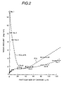
- Fig. 2 is a diagram showing the above relationship between a particle size of carbide particles and a wear amount.
- the roller made of a sintered body containing carbide particles having a particle size of from 15 to 120 ⁇ m exhibits a high wear resistance.
- the wear amount becomes larger with an increase in the particle size of carbide particles, and particularly it becomes relatively rapidly larger when the average particle size exceeds 50 ⁇ m.
- the particle size of carbide particles for making smaller the wear amounts of both the roller and the pin is in a range of from 15 to 80 ⁇ m, preferably, in a range of from 20 to 60 ⁇ m.
- the wear amount is large when the particle size of carbide particles is less than 5 ⁇ m; it is small when the particle size is in a range of from 10 to 100 ⁇ m; and it becomes again large when the particle size is more than 100 ⁇ m.
- Table 4 shows the result of a wear test performed in the same manner as described above, except that the hard phase was made of a chromium nitride and the size of the nitride particles was changed.
- the particle size of the nitride particles is in a range of from 20 to 100 ⁇ m, the wear amount becomes smaller, that is, the wear resistance is excellent as compared with the related art cobalt-based alloy.
- Table 4 it is revealed that the relationship between the size of nitride particles and a wear amount for the sintered body containing chromium nitride particles is substantially similar to that for the sintered body containing chromium carbide particles.
- the total wear amount of the roller and the pin each of which contains either chromium carbide particles or chromium nitride particles is less than that of the roller and the pin each of which is made of the related art cobalt-based alloy.
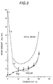
- Table 5 shows a relationship between the mixing ratio of chromium carbide particles and a wear amount for a sintered body using a mixed powder of the nickel alloy powder (A3) and a chromium carbide powder having a particle size of from 20 to 30 ⁇ m.
- the data in Table 3 are plotted in Fig. 3. As can be seen from Table 5 and Fig. 3, when the mixing ratio is 3 vol% or less, the addition effect of the coarse carbide particles is insufficient; and when the mixing ratio is more than 30 vol%, the wear amount is rather increased because of the excessive content of the carbide particles.
- the mixing ratio of chromium carbide particles may be in a range from 5 to 30 vol%, preferably, in a range of from 5 to 25 vol%, more preferably, in a range of from 5 to 20 vol%.
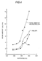
- Table 6 shows a relationship between the hardness of a basic phase and a wear amount.
- the data in Table 6 are plotted in Fig. 4.
- An atomized powder having the nickel alloy composition (A3) added with 6 wt% or less of A1 was prepared, which was mixed with a chromium carbide powder having a particle size of 20 to 30 ⁇ m in a mixing ratio of 10 vol%.
- the mixed powder was sintered and then subjected to solution heat treatment at 1100°C.
- the sintered body thus obtained was further subjected to aging at 750°C in such a manner that the precipitated amount of Ni3Al was changed for changing the hardness of the basic phase.
- the sintered body containing the basic phase having a hardness of 300 Hv or more it may be considered that the carbide particles finely broken by frictional sliding and left on the sliding surface act as abrasive particles, leading to the increased wear amount.
- Content (wt%) of Al in Ni alloy powder Hardness (Hv) of matrix alloy after heat treatment
- Wear amount (mg/km) Roller Pin Total 1 0 185 1.8 1.5 3.3 2 2 237 1.8 1.7 3.5 3 5 286 2.5 2.0 4.5 4 10 321 4.3 3.6 7.9 5 15 352 5.1 3.8 8.9 6 20 385 6.4 5.1 11.5 7 25 415 7.6 6.5 14.1
- Table 7 shows a corrosion reduction of a sintered alloy left for 3000 hours in high temperature water (288°C) containing 8 ppm of dissolved oxygen.
- the sintered alloy of the present invention containing 15 wt% or more of Cr exhibits a corrosion reduction less than that of stellite, that is, it has an excellent corrosion resistance.
- the Cr content is more than 30%, the effect exerted on the corrosion reduction is saturated.
- Table 8 shows a result of examining a toughness of a roller material of the present invention by Sharpy impact test.
- the roller material of the present invention is very higher in impact value than stellite.
- Roller material hard phase size ( ⁇ m) of particles in hard phase Volume ratio V-notch Charpy impact value (kg-m/cm 2 ) A3 (Ni-based) Chromium carbide 20 ⁇ 30 10 2.5 B3 (Fe-based) Chromium nitride 20 ⁇ 30 10 1.7 Stellite #3 0.2
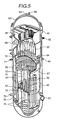
- Fig. 5 is a partial sectional view of a core of a boiling water reactor.
- the reactor in this embodiment is operated at a steam temperature of 286°C and at a steam pressure of 70.7 atm, and it can output powers of 500, 800, and 1100 MW.
- the core includes a neutron source pipe 51, a core supporting plate 52, a neutron counter tube 53, control rods 54, a core shroud 55, an upper grid plate 56, fuel assemblies 57, a spray nozzle 58 provided an end plate, a vented nozzle 59, a pressure vessel cover 60, a flange 61, a measuring nozzle 62, a steam separator 63, a shroud head 64, an inlet nozzle 65 for feed water, a jet pump 66, a steam drier 68, an outlet nozzle 69 for steam, a spar jar 70 for feed water, a nozzle 71 for core spray, a lower core grid 72, an inlet nozzle 73 for recirculation of water, a buffle plate 74, and control rod guide pipes 75.
- the above upper grid plate 56 has a rim barrel 21, flanges 22 and grid plates 35, each of which is formed of a rolled plate made of a polycrystalline stainless steel (SUS316).
- the grid plates 35 only cross and not fixed to each other.
- the core supporting plate 52 is also formed of one rolled plate made of the polycrystalline stainless steel (SUS316), and it has holes for mounting fuel fixtures and is fixed at its circumferential surface to a reactor vessel. Accordingly, each of the upper grid plate 56 and the core supporting plate 52 has not any welded portion at the center portion receiving neutron irradiation.
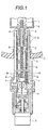
- Fig. 1 is a sectional view of a control rod driving mechanism enabling fine adjustment of a control rod by an electric motor.
- a roller of the present invention, used for the control rod driving mechanism was fabricated by sintering a mixed powder of the nickel alloy powder containing 25 wt% of Cr (Sample A4 in Table 1) and chromium carbide (Cr3C2) particles having a particle size of 20-30 ⁇ m at a mixing ratio of 10 vol%, in the same manner as that in Embodiment 1.
- the pin shown in Table 2 was also fabricated in the same manner as in Embodiment 1.
- the control rod driving mechanism in this embodiment is so configurated that a control rod 1 is vertically driven, through a hollow piston 4, by a driving piston 7 moved by means of a piston driving screw 9 rotated by a motor 3.
- the control rod driving mechanism is welded to a nuclear pressure vessel 2.
- the control rod 1 is driven in a control rod guide pipe 5.
- a hydraulic driving piston 10 is used for rapidly lifting up the control rod 1 by insertion of water from a water insertion piping 8 in case of emergency, and it is separated from the driving piston 7.
- each member, being in contact with high temperature water, of the control rod driving mechanism is made of a stainless steel (SUS316L).
- the control rod 1 has a structure dropped by its dead weight.
- a set of the roller and the pin in this embodiment are disposed at each of portions A to H between the hollow piston 4 and each tube provided in a housing 6 for the purpose of smooth movement of the hollow piston 4.
- the portion A is a buffer portion. Four pieces of the buffer portions A are spaced at intervals of 90° for each of upper and lower sides.
- the portion B is a stop piston portion; C is a spindle head portion; D is a ball screw upper portion; E is a latch supporting portion; F is a latch outer surface portion, and G is a hollow piston/ball nut portion. With respect to each of the portions A to G, four pieces are disposed for each of the upper and lower sides.
- the portion H is a middle flange portion. Six pieces of the middle flange portions H are provided along the circumference.
- the shapes of the roller and the pin used for each portion are as follows.
- Fig. 6 is a sectional view showing a roller 16 provided at the portion A and a pin 17 inserted in the roller 16.
- the pin 17 is restricted in rotation by pressing pins 18.
- the pin 17 has a large diameter portion, an intermediate diameter portion, and a small diameter portion.
- the roller 16 has an inner peripheral portion (pin insertion portion) having a large thickness and an outer peripheral portion having a relatively small thickness.
- Fig. 7 is a sectional view showing a roller 16 provided on the outer side of the portion C and a pin 17 inserted in the roller 16
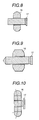
- Fig. 8 is a sectional view of a roller 16, having a similar oval shape in section, provided on the inner side of the portion C and a pin 17 inserted in the roller 16.
- a set of a roller and a pin, each of which has a structure similar to that shown in Fig. 6, are provided at the portion D, wherein the pin 17 has a head portion having a large diameter, which straightly extends up to the surface, opposite to the head portion, of a pin insertion portion of the roller.
- Fig. 9 shows a set of a roller 16 and a roller 17 provided at the portion G
- Fig. 10 is a set of a roller 16 and a pin 17 provided at the portion H.
- the former uses a ball nut roller/pin, in which the pin 17 has a leading end formed in a cone shape and a head portion having a diameter slightly larger than that of the pin insertion portion of the roller.
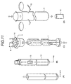
- Figs. 11(A) to 11(D) show an arrangement for assembly of the control rod 1 driven by the control rod driving mechanism 11, the fuel assemblies (A) and (B), a center fuel supporting fixture 14, and a core supporting plate 12.
- Fig. 11(A) shows the fuel assembly having no handle which is arranged at a portion "b" in Fig. 11(C); and
- Fig. 11(B) shows the fuel assembly having a handle which is arranged at a position "a" in Fig. 11(C).
- the supporting fixture 14 for supporting the fuel assemblies is brought in contact with the core supporting plate 12 and fixed hereto.
- the alloy No. 5 shown in Table 1 was used for a sheath, B4C tube or Hf tube of the control rod 1.
- Each of the B4C and Hf tubes was fabricated by repeatedly performing cold-rolling and annealing for a raw tube prepared by hot-rolling using a Pilger rolling mill.
- the sheath was fabricated by repeatedly performing cold-rolling and annealing for a raw plate, and forming a sheath by welding the sheet thus obtained.
- Fig. 12 is a sectional view of a fuel assembly of the present invention which is used for a boiling water reactor.
- the BWR fuel assembly includes a plurality of fuel rods 21, multi-steps of spacers 27 for holding the fuel rods at specified intervals, a square tube shaped channel box 24 for containing them, upper tie plates 25 and lower tie plates 26 for holding both the ends of the fuel rods 21 each having fuel pellets contained in a fuel sheath, water rods 22 disposed at the center of the spacers,and a handle 31 for carrying the entire fuel assembly.
- the fuel assembly is fabricated in accordance with the known processes.
- the channel box 24 contains the fuel rods integrated by the spacers 27 and the water rods 22, and it is fixed to the upper tiel plates 25 and the lower tie plates 26 by means of the water rods 22.
- the channel box 24 is formed into a square tube shape by joining two pieces of U-shaped plates (length: 4 m; thickness: 80, 100, 120 mm)to each other by plasma welding.
- the channel box 24 acts to rectify both steam generated on the surfaces of the fuel rods and high temperature water flowing between the fuel rods upon operation of the plant, and to forcibly introduce them upward.
- the channel box 24 is operated for a long time in such a state as to be applied with a stress spreading the square tube outward because the inner pressure is slightly higher than the outer pressure.
- each fuel rod is not fixed on the tie plates.
- the channel box is preferably subjected to a heat treatment in such a manner that the orientation ratio (Fr value) in the plate thickness direction (the crystal orientation ⁇ 0001>) is in a range of 0.25 to 0.6; the orientation ratio (Fl) in the longitudinal direction is in a range of from 0.25 to 0.4; and the orientation ratio (Ft) in the lateral direction is in a range of from 0.25 to 0.4.
- Fr is in a range of from 0.25 to 0.5;
- Fl is in a range of from 0.25 to 0.36; and
- Ft is in a range of from 0.25 to 0.36.
- an average grain size of ⁇ Zr crystals is in a range of from 50 to 300 ⁇ m (preferably, in a range of 100 to 200 ⁇ m). This is effective to significantly prevent elongation due to irradiation and eliminate occurrence of bending, and hence to prevent the interfere between the channel box and the control rod.
- the channel box can be used even in a condition of a burnup of 45 GWd/t or more for example,60 GWd/t) or even in the case being disposed near the periphery, without any problem.
- the channel box can be used for the conventional burnup 32 GWd/t with fuels being replaced.
- the bending at the outermost periphery is 0.9 mm per year (burnup: 8 GWd/t), and it becomes 0.8 mm for Fr of 0.6; 0.45 mm for Fr of 0.5; and 0.15 mm for Fr of 0.4. Accordingly, for a burnup of 45 GWd/t, the. related art material having Fr of 0.67 cannot be prevented from interfering with the control rod by the bending generated at the outer periphery for one year and by the bending generated at the center portion for 4.5 years.
- the interfere can be prevented even by the bending generated at the outermost periphery for one year and even by the bending generated at the center portion for 4.5 years.
- the interfere can be prevented even by the bending generated at the outermost periphery for 4 years and even by the bending generated at the center portion for 1.5 years.
- the interfere can be perfectly prevented even by the bending generated at the outermost periphery for 5.5 years.
- the channel box was fabricated by the steps of preparing a plate made of a Zr-based alloy shown in Table 9,cold-bending the plate into a U-shape member having a length of 4 m, and joining two pieces of the U-shaped members to each other by laser or plasma welding, thereby obtaining a square tube 12.
- the irregularities at the welded portions were flattened.
- the square tube was heated in a ⁇ phase forming temperature range by high frequency induction heating and then rapidly cooled using cooling water sprayed from a nozzle provided directly under a high frequency induction heating coil. The square tube was allowed to pass through the heating coil from top to down at a specified speed, thus completing the entire heat treatment.
- the feed speed of the square tube and the output of the high frequency power supply were set such that the heating temperature was 1100°C and the holding time over 980°C was ten seconds or more.
- the square tube may be heated in a range of from 1000 to 1200°C, and preferably, it may be held in a temperature range of from 1050 to 1100°C for a time of from 3 to 10 seconds.
- the square tube was cut into test pieces each having a size (width: 40 mm, length: 40 mm) for measurement of the F values. The result is shown in Table 10.
- the heat treatment parameter (P) is 1.96.
- the heat treatment was performed with the square tube 12 fixed on a mandrel 18 made of an austenite stainless steel at both the ends by means of screws.
- channel box has a constant wall thickness
- a corner portion is thicker than that of the side portion and the upper side portion becomes thinner from the lower side portion (longitudinal thickness distribution).
- the formation of this. channel box having the thickness distribution is performed after heat treatment by chemical etching using a mixed solution of hydrogen fluoride and nitric acid after masking or by machining.
- the outer side of the channel box is recessed; however, the inner side may be recessed.
- each member can be used without any replacement for 30 years, and also used without any replacement for 40 years in combination with periodic inspection.
- the reactor temperature is 288°C;
- the periodic inspection is, after operation for 12 months, repeatedly carried out one time per 50 months or less, preferably, one time per 40 months or less, more preferably, one time per 30 day;
- the availability factor becomes 85% or more, preferably,. 90% or more, more preferably, 92% or more; and the thermal efficiency becomes 35%.
- the fuel assembly and the control rod driving mechanism identical to those in Embodiment 2 are applied to an advanced boiling water reactor (ABWR).
- ABWR advanced boiling water reactor
- the reactor pressure vessel is an essential equipment for a nuclear reactor plant.
- a nozzle portion mounting an internal pump is preferably of a sleeve type so that changes in temperature and pressure generated in the reactor pressure vessel do not exert any effect on the rotational function of the internal pump and the thermal transmission to an electric motor unit is made smaller.
- In-core structures reduce an effect of the internal pump exerted on vibration by fluidization.
- the measurement for the core flow rate is performed at a high accuracy in combination with experimental examination performed in consideration of a partial operation state of the internal pump.
- the flow rate of steam flowing in the turbine is measured at a high accuracy using a venturi structure provided in a main steam nozzle portion of the reactor pressure vessel.
- the RPV reactor pressure vessel
- the conventional RPV has an inside diameter of about 6.4 m and contains 764 pieces of the fuel assemblies, a jet pump and structures.
- the RPV in the ABWR, the RPV has an inside diameter of about 7.1 m for containing 872 pieces of the fuel assemblies and ensuring a handling space of the inner pump.
- the related art RPV has an inner height of about 22 m
- the RPV in the ABWR has an inner height of about 21 m on the basis of the following factors (a) to (d).
- the shape of the lower end plate was changed from the conventional semi-spherical shape to the disk-like shape for ensuring a space required for installation of the inner pump onto the lower portion of the pressure vessel and in consideration of a circulating passage of cooling water. Furthermore, the internal pump was integrally formed by forging for reducing the number of welded portions.
- the supporting plate was designed to have a cone barrel for ensuring a space required for handling the internal pump and for disposing a heat exchanger of the internal pump in a pedestal.
- the provision of the internal pump eliminates the coolant recirculating inlet/outlet nozzles of the related art plant, so that a large diameter nozzle is not required to be disposed under a barrel core region. Accordingly, it is not required to suppose a large accident such as loss of coolant.
- a flow rate limiter is disposed at a trailing portion extending to a separation valve on a main steam pipe; however, in this embodiment, the flow rate limiter is disposed on a main steam nozzle so that the safety allowance for a main steam piping breakage is improved and the housing space is optimized.
- the in-core structures in the RPV mainly function to support the core, to form a passage for coolant, and to separate hot water and steam generated in the reactor from each other; and also they are required for sufficient safety and reliability, for example, conservation of a core water injection passage for cooling water under a hypothetical accident.
- Reactor container type Reinforced concrete lining Steel made self-supporting type Turbine type TC6F-52 type (two-stepped re-heating) TC6F-41/43 (non-reheating) Steam separator Double tube, three-stepped type x 349 pieces Triple tube, two-stepped type x 225 pieces Feed water spar jar, thermal sleeve welded type double thermal sleeve Welded type thermal sleeve High pressure water injection spar jar for core Water injuction type Spraying type Low pressure water injection spar jar Down come injuction type In-shroud injection type Upper lattice plate Integrally machining type Lattice plate fitting type Core supporting plate Cross-reinforced beam Parallel reinforced beam In-core stabilizer Two-stepped, fixture on shroud One-stepped, no fixture on shroud Control rod No speed limiter Bayonet coupling type Speed limiter, equipped Spade coupling type Shroud support leg Heighe: 21.7 inch.
- Table 12 shows the basic specifications regarding plant steam turbines and generators of the ABWR plant and the BWR plant.
- the ABWR plant is a high efficiency plant improved from the BWR plant, for example, in terms of the reactor thermal power (improved by 19.2%) and the electric output (improved by 23.3%) at 50 Hz.
Landscapes
- Chemical & Material Sciences (AREA)
- Engineering & Computer Science (AREA)
- Organic Chemistry (AREA)
- Materials Engineering (AREA)
- Mechanical Engineering (AREA)
- Metallurgy (AREA)
- Physics & Mathematics (AREA)
- Dispersion Chemistry (AREA)
- Chemical Kinetics & Catalysis (AREA)
- Plasma & Fusion (AREA)
- General Engineering & Computer Science (AREA)
- High Energy & Nuclear Physics (AREA)
- Powder Metallurgy (AREA)
- Rolls And Other Rotary Bodies (AREA)
Description
- The present invention relates to a wear resisting sintered alloy having excellent wear resistance, corrosion resistance and impact resistance, and particularly to a wear resisting alloy suitable for sliding members used in a control rod driving apparatus of a nuclear reactor plant.
- Cobalt-based alloys have been used for sliding members of a nuclear reactor plant. Specifically, a cobalt alloy called "stellite" has been applied to guide rollers or bushes for a control rod. This cobalt alloy contains 28-30 wt% of Cr, 2-2.5 wt% of C, and small amounts of W, Fe and Ni, the balance being Co. This alloy is excellent in corrosion resistance because of the high content of Cr, and also it is high in hardness because of the high content of C, leading to an excellent wear resistance.
- A member made of such an alloy, however, presents a disadvantage when placed in a reactor water at a high temperature and a high pressure. Namely, in this case, cobalt is eluted in the reactor water; the eluted cobalt adheres on the surface of a fuel sheath tube and is radio-activated; and the radio-activated cobalt is eluted again and circulated in the reactor water. As a result, the exposure dose is increased upon periodic inspection or repair for the plant, to extend a shutdown period, thus reducing the availability factor of the plant.
- To prevent an increase in exposure dose due to elution of cobalt, it is necessary to use a new sliding material as substitute for a cobalt-based alloy.
- Japanese Patent Publication No. Sho 59-52228 has already disclosed a sliding material not containing cobalt as a main component. Specifically, a nickel-based alloy is used as a roller material; however, since the alloy has a wear resistance lower than that of a cobalt-based alloy, it causes a large dimensional change due to wear and is poor in long-term service when used as a roller material for a sliding portion applied with a high mechanical load. Also, Japanese Patent Publication No. Sho 58-23454 has disclosed a nickel-based alloy containing Cr and Nb; however, it is poor in impact value and thereby low in reliability when applied with an impact load at the time of scram.
- WO-A-92/11941 describes a sintered material for wear applications. It comprises an iron-based alloy, which forms a soft matrix of 250-800 HV, in which grains of hard materials of at least 1000 Hv are dispersed.
- An object of the present invention is to provide a wear resisting alloy which can be superior in wear resistance to stellite, high in reliability for an impact load due to high speed driving at the time of scram, and low in exposure dose by elimination of elution of cobalt, thereby ensuring the smooth driving of a reactor control rod using the alloy in high temperature water and at a high load for a long time. A further object of the present invention is to provide a control rod driving apparatus and a nuclear reactor using the above alloy.
- The present invention provides a wear resisting sintered alloy as set out in
claim 1. - The present invention also provides a control rod driving apparatus as set out in
claim 5 including a housing, a hollow piston provided in said housing, a driving piston for vertically driving said hollow piston, rollers provided on a tube between said hollow piston and the tube provided in said housing, and pins functioning as rotating shafts of said rollers, wherein each of said rollers is made of a sintered alloy of the invention. - Preferably each of the pin and the roller is made of an iron-based or a nickel-based alloy having a wear characteristic such that the total wear amount of said roller and said pin is within a range of 10 mg or less per unit area (sliding width 7.5 mm× sliding
distance 1 km) in a wear test performed under a load of 1 kg per sliding width of 0. 75 mm in water at a temperature of 288°C. - The roller may be made of an iron-based or a nickel-based alloy having a wear characteristic such that the wear amount of said roller is within a range of 8.5 mg or less per unit area (sliding width 7.5 mm×sliding
distance 1 km) in a wear test relative to said pin performed under a load of 1 kg per sliding width of 0.75 mm in water at a temperature of 288°C. - The pin may be made of an iron-based or a nickel-based alloy having a wear characteristic such that the wear amount of said pin is within a range of 4.5 mg or less per unit area (sliding width 7.5 mm×sliding
distance 1 km) in a wear test relative to said roller performed under a load of 1 kg per sliding width of 0.75 mm in water at a temperature of 288°C. - The present invention also provides a nuclear reactor as set out in
claim 9. - The present invention also provides a roller for a control rod driving apparatus, which is made of a wear resisting sintered alloy of the invention.
- The present invention also provides a method of producing a wear resisting sintered alloy as set out in
claim 11. - A control rod driving apparatus of a nuclear plant is being changed from the conventional hydraulic driving type to a motor-driven type enabling fine adjustment. The new type control rod driving apparatus uses guide rollers for making smooth the movement of a hollow piston. The guide roller is applied with a load very larger than that applied to the guide roller used for the related art control rod, and thereby it requires a higher wear resistance.
- In this roller, there occurs wear mainly on the inner peripheral surface of the roller and on the outer surface of a fixed pin for supporting the roller. More specifically, since the roller is slid on the pin in high temperature water without any lubrication, there occurs adhesive wear due to relative sliding movement between the roller and the pin. In the adhesive wear, a shearing stress produced at the contact portion due to adhesion forms a plastic flow layer near the sliding surface. By repeated sliding, part of the plastic flow layer is finally broken and separated into a wear powder. Accordingly, to reduce a damage due to adhesive wear, it is necessary to impart a specified level or more of hardness or strength to the alloy for suppressing the plastic deformation at the contact portion. For this reason, a sliding member is made of an alloy in which a hard phase is precipitated or dispersed in a matrix for reinforcement of the strength by adjustment of a chemical composition of the alloy. When the hardness is excessively increased, the toughness is decreased and thereby the impact resistance is reduced, so that the chemical composition for the alloy must be suitably adjusted. The hard phase in the related art material is effective in terms of suppressing plastic deformation of the sliding surface and improving the wear resistance; however, it is not effective in terms of suppressing the most essential adhesion for the wear resistance. Specifically, the size of particles forming the hard phase of the related art material is relatively small, so that the surfaces of the particles forming the hard phase are easily covered with the metal forming abasic phase due to plastic flow. This exerts adverse effect on suppression of adhesion. Furthermore, since a guide roller in a control rod driving mechanism is used in high temperature water for a long time, a material used for the guide roller is additionally required to be excellent in corrosion resistance.
- In view of the foregoing, the present invention has been made. Namely, an important feature of the present invention lies in that particles of a hard phase, having a particle size sufficiently large not to be perfectly covered by plastic flow, are suitably dispersed in a relatively soft matrix. These coarse particles of the hard phase not only suppress plastic flow, but prevent adhesion because they are exposed from the wear surface and thereby not perfectly covered with the soft matrix by plastic flow. Another reason why coarse particles of a hard phase are dispersed is that when part of the sliding surface is weared by sliding with a mating material, the exposed portions of the coarse particles are finely broken and densely dispersed on the sliding surface and then buried in a relatively soft matrix, as a result of which a sliding surface stronger than that before being weared is formed. In other words, the dispersion of the coarse particles of the hard phase in the soft matrix as fine particles results in the self-compensation function, to significantly improve the wear resistance. In this case, the particle size of the coarse particles of the hard phase made of a carbide, nitride or boride is preferably 20 µm or more for contributing to suppression of adhesion without covering with the soft matrix due to plastic flow. In general, as the particle size of coarse particles of a hard phase become larger, the effect of suppressing the adhesion is increased. However, when the particles size is more than 100 µm, the effect may be saturated and rather the impact characteristic may be degraded. The dispersed amount of coarse particles of a hard phase may also be an important factor of the present invention. When coarse particles of a hard phase are dispersed in a soft matrix in an amount of 5 vol% or more, the effect becomes significantly larger; while when they are dispersed in the matrix in an amount of 30 vol% or more, the wear amount is rather increased. For this reason, a preferable dispersed amount of coarse particles of a hard phase is in a range of from 5 to 30 vol%.
- A basic phase contained in an alloy of the present invention requires a sufficiently soft hardness in order that finely broken particles of a hard phase are buried in the basic phase. It must be also selected in terms of corrosion resistance for high temperature water. As a result, a nickel-based or iron-based alloy containing Cr, which has a hardness of 231 Hv or less, is preferred to form the above basic phase. When the Cr content is less than 15 wt%, the corrosion resistance in high temperature water may be insufficient; while when it is more than 30 wt%, the toughness is rather reduced. Consequently, the Cr content is in a range of from 15 to 30 wt%, more preferably, in a range of from 20 to 25 wt.%.
- C is an element for reinforcing the matrix. However, in order to ensure the soft matrix, the C content is in a range of from 0.03 to 0.005 wt%.
- Si is added to a deoxidizing agent used for producing an alloy powder. The Si content may be in a range of 1 wt% or less, preferably, in a range of from 0.05 to 0.5 wt%.
- Mn has the same effect as that of Si. The Mn content may be in a range of 2 wt% or less, preferably, in a range of from 0. 1 to 0.5 wt%. In addition, Mn and Si may be not added.
- A1 is added in an amount of 6 wt% or less for increasing the oxidation resistance and reinforcing the matrix. This element is preferably added to a Ni-based alloy.
- Ni is added to a Fe-based alloy in an amount of 8-20 wt% to obtain an austenite stainless steel. The Fe content is preferably in a range of from 8 to 13 wt%.
- Hard particles are dispersed in a sintered alloy in the form of non-precipitated or non-crystallized phase, and preferably, they have a particle size sufficiently large to be broken upon sliding with a mating member on a sliding surface. In particular, an average particle size of the hard particles is preferably in a range of 10 to 120 µm, more preferably, in a range of 20 to 100 µm. The hard particles may be made of a non-oxide material because of its high adhesion with the matrix, preferably, made of a carbide, nitride or boride, more preferably, made of a carbide or nitride. When the hard particles have an excessively high hardness, they tend to accelerate wear of the mating material. Accordingly, the hardness of the hard particles is in a range of 1000 to 2100 Hv, preferably, in a range of 1000 to 1550 Hv.
- Carbides include B4C (5000 Hv),SiC (4200 Hv), TiC (3200 Hv), ZrC (2800 Hv), VC (2100 Hv), NbC (2050), TaC (1550 Hv), Cr3C2 (1300 Hv), Mo2C (1500 Hv), and WC (1780 Hv). Of these carbides, those of hardness 2100 Hv or lower are suitable. Suitable examples of borides include, VB2 (2070 Hv) and CrB2 (1800 Hv). Specific examples of silicides include TiSi2 ( 870 Hv),ZrSi (1125 Hv), VSi2 (1090 Hv), Nb5Si2 (1050 Hv), TaSi2 (1563 Hv), Cr3Si2 (1280 Hv), MoSi2 (1290 Hv), and WSi2 (1090 Hv).
- A Fe-based sintered alloy preferably includes a matrix having a stainless steel composition containing 0.005 to 0.03 wt% of C, 1 wt% or less of Si, 2 wt% or less of Mn, 15-30 wt% of Cr, and 18-20 wt% of Ni, and having a hardness of not more than 237 Hv, and hard particles added to the matrix in an amount of from 5 to 30 vol%. More preferably, the content of each element is within the range specified as described above.
- A Ni-based sintered alloy preferably includes a matrix having a composition containing 0.005 to 0.03 wt% of C, 1 wt% or less of Si, 2 wt% or less of Mn, and 15-30 wt% of Cr, and having a hardness of not more than 237 Hv, and hard particles added to the matrix in an amount of from 5 to 30 vol%. In addition, preferably, the alloy forming the matrix further contains A1 in an amount within the range specified as described above.
- A wear resisting alloy containing no cobalt according to the present invention can be used for a sliding member in a control rod driving apparatus. In this case, since the alloy eliminates elution of cobalt in a reactor water at a high temperature and at a high pressure, it is possible to suppress the exposure dose due to the induced radio-activation. Since the alloy is superior in wear resistance to stellite, the sliding member using the alloy is small in dimensional change due to wear, thus enabling precision driving. In addition, since the sliding member using the alloy is excellent in corrosion resistance and impact resistance, it is possible to ensure high reliability for long-term operation or high speed driving in case of emergency.
- Figure 1 is a sectional view of a control rod driving apparatus,
- Figure 2 is a diagram showing a relationship between a wear amount and a particle size of carbide,
- Figure 3 is a diagram showing a relationship between a wear amount and a content of carbide,
- Figure 4 is a diagram showing a relationship between a wear amount and a hardness in Vickers,
- Figure 5 is a partial sectional view of a nuclear reactor,
- Figure 6 is a sectional view of a pin and a roller,
- Figure 7 is a sectional view of a pin and a roller,
- Figure 8 is a sectional view of a pin and a roller,
- Figure 9 is a sectional view of a pin and a roller,
- Figure 10 is a sectional view of a pin and a roller,
- Figures 11(A) to 11(D) are views showing an assembly of a control rod driving mechanism, a fuel assembly, and a control rod,
- Figure 12 is a sectional view of a fuel assembly.
-
- In the drawings:-
- 1, 54: control rod, 2: pressure vessel, 3: motor, 4: hollow piston, 5: control rod guide pipe, 6: housing, 7: driving piston, 8: water insertion piping, 9: piston driving screw, 10: water pressure driving piston, 11: control rod driving mechanism, 12: core supporting plate, 13, 21: fuel rod, 14: fuel fixture, 15, 24: channel box, 16: roller, 17: pin, 18: pressing pin, 27: spacer, 75: control rod guide pipe.
-
- Table 1 shows chemical compositions of alloy powders used for sintered rollers subjected to a sliding wear test. Samples A1 to A6 are nickel alloy powders containing chromium in different amounts, and samples A7 to A12 are nickel alloy powders containing aluminum in different amounts. Each alloy powder was fabricated by atomization to have an average particle size of about 15 µm. This alloy powder was mixed with carbide particles or nitride particles. In this mixing, the particle size of carbide particles or nitride particles was changed and the content of carbide particles or nitride particles was also changed. The mixed powder was then sintered, in vacuum, by electric heating at about 1200 °C in combination with hot-pressing, to fabricate a roller material. The roller material thus obtained was then machined into a suitable size (outside diameter; 17 mm, inside diameter: 5.5 mm, and width: 7.5 mm). In addition, the void ratio of the sintered body was about 1%.
(Roller) Sample C Si Mn Ni Cr Fe Al A1 0.02 0.5 0.5 Bal 9.5 - - A2 0.02 0.5 0.5 Bal 15.2 - - A3 0.02 0.5 0.5 Bal 20.7 - - A4 0.02 0.5 0.5 Bal 25.5 - - A5 0.02 0.5 0.5 Bal 30.5 - - A6 0.02 0.5 0.5 Bal 35.5 - - A7 0.02 0.5 0.5 Bal 20.5 - 0.9 A8 0.02 0.5 0.5 Bal 20.5 - 1.9 A9 0.02 0.5 0.5 Bal 20.5 - 2.9 A10 0.02 0.5 0.5 Bal 20.5 - 4.1 A11 0.02 0.5 0.5 Bal 20.5 - 5.0 A12 0.02 0.5 0.5 Bal 20.5 - 5.9 B1 0.03 0.5 0.5 - 10.2 Bal - B2 0.03 0.5 0.5 - 14.9 Bal - B3 0.03 0.5 0.5 - 20.0 Bal - B4 0.03 0.5 0.5 - 25.2 Bal - B5 0.03 0.5 0.5 - 30.5 Bal - B6 0.03 0.5 0.5 - 30.5 Bal - - Table 2 shows a chemical composition (wt%) of a mating pin material used for the sliding wear test. An ingot fabricated by atmospheric melting was subjected to hot-forging into a rod, and was then subjected to cold-working at a reduction ratio of 30%. The resultant rod was machined into a pin having a diameter of 5.5 mm. In addition, each roller was subjected to the sliding wear test in the as-sintered condition, and the average crystal grain size of the sintered roller was 30 µm.
- For comparison with the alloys of the present invention, commercial cobalt-based alloys, stellite #3 (for roller) and Heinze #25 (for pin), were used.
(Pin) C Si Mn Ni Fe Cr V Cl 0.75 3.5 8.1 8.3 Bal 18.1 3.0 - The sliding wear test was made by a method wherein a roller and a pin inserted in the roller were mounted on a tester, and the roller was pressed through the pin on a rotor made of a stainless steel (SUS316L) at a load of 10 kg in an environment simulating the operating condition of a nuclear reactor, that is, in water at a high temperature of 288°C.
- Table 3 shows a relationship between a particle size of carbide particles and a wear amount for a sintered sample in which a Cr3C2 (chromium carbide) powder is used for formation of a hard phase and the nickel alloy powder containing 20 wt% of Cr (Sample No. A3 in Table 1) is used for formation of a basic phase. The wear test was repeatedly performed for sintered samples in which the particle size of the chromium carbide particles was variously changed. In this case, the content of the carbide particles was specified at 10 vol%. The condition of the wear test was as follows: the sliding speed was 0.03 cm/s and the running distance was 10 km. In addition,the wear amount was expressed in a weight reduction per 1 km. As shown in Table 3, when the size of the chromium carbide particle is more than 20-30 µm, the wear amount of each of the roller and the pin is significantly decreased, particularly, becomes very smaller than that of the related art cobalt-based alloy. On the other hand, when the size of the chromium carbide particles is more than 100 µm, the wear amount of each of the roller and the pin is slightly increased. As a result, the size of chromium carbide particles is preferably in a range of 20 to 100 µm.
- Table 3 shows corresponding usults for an iron-based alloy (B3).
No. Roller material Pin material Wear amount (mg/km) Alloy powder for matrix Particle size of carbide (µm) Roller Pin Total 1 A3 1 or less Cl 15.3 0.5 15.8 2 A3 1 ∼ 5 Cl 10.2 0.8 11.0 3 A3 5 ∼ 10 Cl 8.5 1.2 9.7 4 A3 20 ∼ 30 Cl 1.8 1.5 3.3 5 A3 40 ∼ 60 Cl 1.9 2.1 4.0 6 A3 80 ∼ 100 Cl 2.6 4.5 7.1 7 A3 110 ∼ 130 Cl 3.7 6.3 10.0 8 B3 5 or less Cl 11.5 1.2 12.7 9 B3 5 ∼ 10 Cl 8.3 1.1 9.4 10 B3 20 ∼ 30 Cl 3.0 1.5 4.5 11 B3 40 ∼ 60 Cl 2.5 2.2 4.7 12 B3 110 ∼ 130 Cl 3.1 4.8 7.9 13 Stellite #3 - Heinze # 256.5 2.1 8.6 - Fig. 2 is a diagram showing the above relationship between a particle size of carbide particles and a wear amount. As shown in this graph, the roller made of a sintered body containing carbide particles having a particle size of from 15 to 120 µm exhibits a high wear resistance. On the other hand, with respect to the pin, the wear amount becomes larger with an increase in the particle size of carbide particles, and particularly it becomes relatively rapidly larger when the average particle size exceeds 50 µm. In particular, it is revealed that the particle size of carbide particles for making smaller the wear amounts of both the roller and the pin is in a range of from 15 to 80 µm, preferably, in a range of from 20 to 60 µm.
- With respect to each of a roller and a pin made of a sintered body including a basic phase having an austenite stainless steel composition (shown in Table 3) and chromium carbides dispersed in the basic phase, the wear amount is large when the particle size of carbide particles is less than 5 µm; it is small when the particle size is in a range of from 10 to 100 µm; and it becomes again large when the particle size is more than 100 µm.
- Table 4 shows the result of a wear test performed in the same manner as described above, except that the hard phase was made of a chromium nitride and the size of the nitride particles was changed. In this case, when the particle size of the nitride particles is in a range of from 20 to 100 µm, the wear amount becomes smaller, that is, the wear resistance is excellent as compared with the related art cobalt-based alloy. As can be seen from Table 4, it is revealed that the relationship between the size of nitride particles and a wear amount for the sintered body containing chromium nitride particles is substantially similar to that for the sintered body containing chromium carbide particles.
- The total wear amount of the roller and the pin each of which contains either chromium carbide particles or chromium nitride particles is less than that of the roller and the pin each of which is made of the related art cobalt-based alloy.
No. Roller material Pin material Wear amount (mg/km) Alloy powder for matrix Particle size of carbide (µm) Roller Pin Total 1 A3 1 or less Cl 16.3 0.6 16.9 2 A3 1 ∼ 5 Cl 12.8 1.0 13.8 3 A3 5 ∼ 10 Cl 10.2 1.2 11.4 4 A3 20 ∼ 30 Cl 4.5 1.8 6.3 5 A3 40 ∼ 60 Cl 3.8 2.6 6.4 6 A3 80 ∼ 100 Cl 3.6 4.1 7.7 7 A3 110 ∼ 130 Cl 4.6 7.0 11.6 8 B3 5 or less Cl 11.8 1.2 13.0 9 B3 5 ∼ 10 Cl 10.2 1.0 11.2 10 B3 20 ∼ 30 Cl 4.3 1.0 5.3 11 B3 40 ∼ 60 Cl 3.7 2.5 6.2 12 B3 110 ∼ 130 Cl - 4.4 4.5 8.9 13 Stellite #3 - Heinze # 256.5 2.1 8.6 - Table 5 shows a relationship between the mixing ratio of chromium carbide particles and a wear amount for a sintered body using a mixed powder of the nickel alloy powder (A3) and a chromium carbide powder having a particle size of from 20 to 30 µm. The data in Table 3 are plotted in Fig. 3. As can be seen from Table 5 and Fig. 3, when the mixing ratio is 3 vol% or less, the addition effect of the coarse carbide particles is insufficient; and when the mixing ratio is more than 30 vol%, the wear amount is rather increased because of the excessive content of the carbide particles. Accordingly, the mixing ratio of chromium carbide particles may be in a range from 5 to 30 vol%, preferably, in a range of from 5 to 25 vol%, more preferably, in a range of from 5 to 20 vol%.
Volume ratio (%) of carbide in roller material Wear amount (mg/km) Roller Pin Total 1 0 15.3 0.5 15.8 2 2 10.8 0.5 11.3 3 5 3.2 1.1 4.3 4 10 1.8 1.5 3.3 5 15 1.5 1.8 3.3 6 20 1.9 2.2 4.1 7 25 2.9 2.8 5.7 8 30 5.5 5.6 11.1 - Table 6 shows a relationship between the hardness of a basic phase and a wear amount. The data in Table 6 are plotted in Fig. 4. An atomized powder having the nickel alloy composition (A3) added with 6 wt% or less of A1 was prepared, which was mixed with a chromium carbide powder having a particle size of 20 to 30 µm in a mixing ratio of 10 vol%. The mixed powder was sintered and then subjected to solution heat treatment at 1100°C. The sintered body thus obtained was further subjected to aging at 750°C in such a manner that the precipitated amount of Ni3Al was changed for changing the hardness of the basic phase. As can be seen from Table 6 and Fig. 4, when the hardness of the basic phase is as small as about 200 Hv, the wear amount is small; and when it is more than 300 Hv, the wear amount becomes larger. In general, a wear amount of an alloy becomes smaller with an increase in hardness of the alloy (HOLM's law). The above relationship, however, is reversed to the general wear law by the unique effect of coarse carbide particles. As a result of fine observation for the wear section of the roller after the wear test, it was recognized only for the sintered body containing the soft basic phase that chromium carbide particles were finely broken and buried in the wear surface. On the other hand, for the sintered body containing the basic phase having a hardness of 300 Hv or more, it may be considered that the carbide particles finely broken by frictional sliding and left on the sliding surface act as abrasive particles, leading to the increased wear amount.
Content (wt%) of Al in Ni alloy powder Hardness (Hv) of matrix alloy after heat treatment Wear amount (mg/km) Roller Pin Total 1 0 185 1.8 1.5 3.3 2 2 237 1.8 1.7 3.5 3 5 286 2.5 2.0 4.5 4 10 321 4.3 3.6 7.9 5 15 352 5.1 3.8 8.9 6 20 385 6.4 5.1 11.5 7 25 415 7.6 6.5 14.1 - Table 7 shows a corrosion reduction of a sintered alloy left for 3000 hours in high temperature water (288°C) containing 8 ppm of dissolved oxygen. In this test, the sintered alloy of the present invention containing 15 wt% or more of Cr exhibits a corrosion reduction less than that of stellite, that is, it has an excellent corrosion resistance. When the Cr content is more than 30%, the effect exerted on the corrosion reduction is saturated.
No. Content (wt%) of Cr in Ni alloy powder Corrosion reduction (mg/cm2) of roller material in high temperature water 1 5 3.2 2 10 1.9 3 15 0.8 4 20 0.6 5 25 0.5 6 30 0.5 7 Stellite # 31.2 - Table 8 shows a result of examining a toughness of a roller material of the present invention by Sharpy impact test. The roller material of the present invention is very higher in impact value than stellite.
Roller material hard phase size (µm) of particles in hard phase Volume ratio V-notch Charpy impact value (kg-m/cm2) A3 (Ni-based) Chromium carbide 20∼30 10 2.5 B3 (Fe-based) Chromium nitride 20∼30 10 1.7 Stellite # 30.2 - Fig. 5 is a partial sectional view of a core of a boiling water reactor.
- The reactor in this embodiment is operated at a steam temperature of 286°C and at a steam pressure of 70.7 atm, and it can output powers of 500, 800, and 1100 MW. In this reactor, the core includes a
neutron source pipe 51, acore supporting plate 52, aneutron counter tube 53,control rods 54, a core shroud 55, anupper grid plate 56,fuel assemblies 57, aspray nozzle 58 provided an end plate, a ventednozzle 59, apressure vessel cover 60, aflange 61, a measuringnozzle 62, asteam separator 63, ashroud head 64, aninlet nozzle 65 for feed water, ajet pump 66, a steam drier 68, anoutlet nozzle 69 for steam, aspar jar 70 for feed water, anozzle 71 for core spray, alower core grid 72, aninlet nozzle 73 for recirculation of water, abuffle plate 74, and controlrod guide pipes 75. - The above
upper grid plate 56 has arim barrel 21,flanges 22 and grid plates 35, each of which is formed of a rolled plate made of a polycrystalline stainless steel (SUS316). The grid plates 35 only cross and not fixed to each other. Thecore supporting plate 52 is also formed of one rolled plate made of the polycrystalline stainless steel (SUS316), and it has holes for mounting fuel fixtures and is fixed at its circumferential surface to a reactor vessel. Accordingly, each of theupper grid plate 56 and thecore supporting plate 52 has not any welded portion at the center portion receiving neutron irradiation. - Fig. 1 is a sectional view of a control rod driving mechanism enabling fine adjustment of a control rod by an electric motor. A roller of the present invention, used for the control rod driving mechanism, was fabricated by sintering a mixed powder of the nickel alloy powder containing 25 wt% of Cr (Sample A4 in Table 1) and chromium carbide (Cr3C2) particles having a particle size of 20-30 µm at a mixing ratio of 10 vol%, in the same manner as that in
Embodiment 1. The pin shown in Table 2 was also fabricated in the same manner as inEmbodiment 1. Thus, 32 sets of these rollers and the pins were subjected to a load driving test equivalent to the practical load driving for 40 years in an environment simulating that of a real reactor, that is, in circulated water at a high temperature.As a result, each of the roller and the pin exhibited a dimensional change due to wear, which was small enough to satisfy a design basis, and recognized no breakage caused by an impact load applied upon scram driving. - The control rod driving mechanism in this embodiment is so configurated that a
control rod 1 is vertically driven, through ahollow piston 4, by adriving piston 7 moved by means of apiston driving screw 9 rotated by amotor 3. The control rod driving mechanism is welded to anuclear pressure vessel 2. Thecontrol rod 1 is driven in a controlrod guide pipe 5. Ahydraulic driving piston 10 is used for rapidly lifting up thecontrol rod 1 by insertion of water from a water insertion piping 8 in case of emergency, and it is separated from thedriving piston 7. In particular, each member, being in contact with high temperature water, of the control rod driving mechanism is made of a stainless steel (SUS316L). Thecontrol rod 1 has a structure dropped by its dead weight. - A set of the roller and the pin in this embodiment are disposed at each of portions A to H between the
hollow piston 4 and each tube provided in ahousing 6 for the purpose of smooth movement of thehollow piston 4. The portion A is a buffer portion. Four pieces of the buffer portions A are spaced at intervals of 90° for each of upper and lower sides. The portion B is a stop piston portion; C is a spindle head portion; D is a ball screw upper portion; E is a latch supporting portion; F is a latch outer surface portion, and G is a hollow piston/ball nut portion. With respect to each of the portions A to G, four pieces are disposed for each of the upper and lower sides. The portion H is a middle flange portion. Six pieces of the middle flange portions H are provided along the circumference. The shapes of the roller and the pin used for each portion are as follows. - Fig. 6 is a sectional view showing a
roller 16 provided at the portion A and apin 17 inserted in theroller 16. Thepin 17 is restricted in rotation by pressingpins 18. Thepin 17 has a large diameter portion, an intermediate diameter portion, and a small diameter portion. Theroller 16 has an inner peripheral portion (pin insertion portion) having a large thickness and an outer peripheral portion having a relatively small thickness. - Fig. 7 is a sectional view showing a
roller 16 provided on the outer side of the portion C and apin 17 inserted in theroller 16, and Fig. 8 is a sectional view of aroller 16, having a similar oval shape in section, provided on the inner side of the portion C and apin 17 inserted in theroller 16. A set of a roller and a pin, each of which has a structure similar to that shown in Fig. 6, are provided at the portion D, wherein thepin 17 has a head portion having a large diameter, which straightly extends up to the surface, opposite to the head portion, of a pin insertion portion of the roller. - Fig. 9 shows a set of a
roller 16 and aroller 17 provided at the portion G, and Fig. 10 is a set of aroller 16 and apin 17 provided at the portion H. The former uses a ball nut roller/pin, in which thepin 17 has a leading end formed in a cone shape and a head portion having a diameter slightly larger than that of the pin insertion portion of the roller. - Figs. 11(A) to 11(D) show an arrangement for assembly of the
control rod 1 driven by the controlrod driving mechanism 11, the fuel assemblies (A) and (B), a centerfuel supporting fixture 14, and acore supporting plate 12. Fig. 11(A) shows the fuel assembly having no handle which is arranged at a portion "b" in Fig. 11(C); and Fig. 11(B) shows the fuel assembly having a handle which is arranged at a position "a" in Fig. 11(C). The supportingfixture 14 for supporting the fuel assemblies is brought in contact with thecore supporting plate 12 and fixed hereto. - In this embodiment, the alloy No. 5 shown in Table 1 was used for a sheath, B4C tube or Hf tube of the
control rod 1. Each of the B4C and Hf tubes was fabricated by repeatedly performing cold-rolling and annealing for a raw tube prepared by hot-rolling using a Pilger rolling mill. The sheath was fabricated by repeatedly performing cold-rolling and annealing for a raw plate, and forming a sheath by welding the sheet thus obtained. - Fig. 12 is a sectional view of a fuel assembly of the present invention which is used for a boiling water reactor.
- As shown in Fig. 12, the BWR fuel assembly includes a plurality of
fuel rods 21, multi-steps of spacers 27 for holding the fuel rods at specified intervals, a square tube shapedchannel box 24 for containing them,upper tie plates 25 andlower tie plates 26 for holding both the ends of thefuel rods 21 each having fuel pellets contained in a fuel sheath,water rods 22 disposed at the center of the spacers,and ahandle 31 for carrying the entire fuel assembly. In addition, the fuel assembly is fabricated in accordance with the known processes. - The
channel box 24 contains the fuel rods integrated by the spacers 27 and thewater rods 22, and it is fixed to theupper tiel plates 25 and thelower tie plates 26 by means of thewater rods 22. Thechannel box 24 is formed into a square tube shape by joining two pieces of U-shaped plates (length: 4 m; thickness: 80, 100, 120 mm)to each other by plasma welding. Thechannel box 24 acts to rectify both steam generated on the surfaces of the fuel rods and high temperature water flowing between the fuel rods upon operation of the plant, and to forcibly introduce them upward. Thechannel box 24 is operated for a long time in such a state as to be applied with a stress spreading the square tube outward because the inner pressure is slightly higher than the outer pressure. - In the fuel assembly of the present invention, three pieces of the
water rods 22 are disposed symmetrically with respect to the center of the spacers 27, each of which is fixed at both the ends to the tie plates by means of screws, and thechannel box 24 is fixed on theupper tie plates 25 by means of screws. Accordingly, the fuel assembly can be integrally carried using the handle 31.In this embodiment, each fuel rod is not fixed on the tie plates. - The channel box is preferably subjected to a heat treatment in such a manner that the orientation ratio (Fr value) in the plate thickness direction (the crystal orientation <0001>) is in a range of 0.25 to 0.6; the orientation ratio (Fl) in the longitudinal direction is in a range of from 0.25 to 0.4; and the orientation ratio (Ft) in the lateral direction is in a range of from 0.25 to 0.4. Preferably, Fr is in a range of from 0.25 to 0.5; Fl is in a range of from 0.25 to 0.36; and Ft is in a range of from 0.25 to 0.36. By such a crystal orientation due to heat treatment, an average grain size of β Zr crystals is in a range of from 50 to 300 µm (preferably, in a range of 100 to 200 µm). This is effective to significantly prevent elongation due to irradiation and eliminate occurrence of bending, and hence to prevent the interfere between the channel box and the control rod. As a result, the channel box can be used even in a condition of a burnup of 45 GWd/t or more for example,60 GWd/t) or even in the case being disposed near the periphery, without any problem. Furthermore, the channel box can be used for the conventional burnup 32 GWd/t with fuels being replaced.
- In particular, for the related art channel box material having Fr of 0.67, Fl of 0.11 and Fr of 0.22, the bending at the outermost periphery is 0.9 mm per year (burnup: 8 GWd/t), and it becomes 0.8 mm for Fr of 0.6; 0.45 mm for Fr of 0.5; and 0.15 mm for Fr of 0.4. Accordingly, for a burnup of 45 GWd/t, the. related art material having Fr of 0.67 cannot be prevented from interfering with the control rod by the bending generated at the outer periphery for one year and by the bending generated at the center portion for 4.5 years. On the other hand, for a material having Fr of 0.6, the interfere can be prevented even by the bending generated at the outermost periphery for one year and even by the bending generated at the center portion for 4.5 years. For a material having Fr of 0.5, the interfere can be prevented even by the bending generated at the outermost periphery for 4 years and even by the bending generated at the center portion for 1.5 years. And, for a material having Fr of 0.4 or less, the interfere can be perfectly prevented even by the bending generated at the outermost periphery for 5.5 years.
- The channel box was fabricated by the steps of preparing a plate made of a Zr-based alloy shown in Table 9,cold-bending the plate into a U-shape member having a length of 4 m, and joining two pieces of the U-shaped members to each other by laser or plasma welding, thereby obtaining a
square tube 12. The irregularities at the welded portions were flattened. The square tube was heated in a β phase forming temperature range by high frequency induction heating and then rapidly cooled using cooling water sprayed from a nozzle provided directly under a high frequency induction heating coil. The square tube was allowed to pass through the heating coil from top to down at a specified speed, thus completing the entire heat treatment. The feed speed of the square tube and the output of the high frequency power supply were set such that the heating temperature was 1100°C and the holding time over 980°C was ten seconds or more. The square tube may be heated in a range of from 1000 to 1200°C, and preferably, it may be held in a temperature range of from 1050 to 1100°C for a time of from 3 to 10 seconds. After heat treatment, the square tube was cut into test pieces each having a size (width: 40 mm, length: 40 mm) for measurement of the F values. The result is shown in Table 10. The heat treatment parameter (P) is 1.96. The heat treatment was performed with thesquare tube 12 fixed on amandrel 18 made of an austenite stainless steel at both the ends by means of screws. As can be seen from Table 10, for the (0002) face (bottom plane of a hexagonal column) and the (1010) face (side plane of the hexagonal column), each of the Fr, Fl and Ft becomes substantial 1/3, which exhibits the perfectly random crystal orientation. The average size of β Zr crystal grains was about 100 µm. After the heat treatment, the square tube was formed at a high dimensional accuracy, followed by sand blasting and acid pickling for removing a surface oxide film, and was then subjected to autoclave processing using steam after removal of the surface oxide film.No. Alloy component Sn Fe Cr Ni O Zr 1 1.50 0.21 0.10 - 0.12 bal. 2 1.50 0.15 0.10 0.10 0.12 bal. 3 1.50 0.25 0.10 0.10 0.12 bal. Heat treatment (0001) Face (1010) Face Fr Fl Ft Fr Fl Ft 1100°C/10s 0.333 0.333 0.334 0.333 0.334 0.333 - Although the above channel box has a constant wall thickness, there can be used another example of the channel box in which a corner portion is thicker than that of the side portion and the upper side portion becomes thinner from the lower side portion (longitudinal thickness distribution). The formation of this. channel box having the thickness distribution is performed after heat treatment by chemical etching using a mixed solution of hydrogen fluoride and nitric acid after masking or by machining. In this embodiment, the outer side of the channel box is recessed; however, the inner side may be recessed.
- The main specification of the BWR generating plant having the above configuration is shown in Table 11. In this embodiment, each member can be used without any replacement for 30 years, and also used without any replacement for 40 years in combination with periodic inspection. The reactor temperature is 288°C; the periodic inspection is, after operation for 12 months, repeatedly carried out one time per 50 months or less, preferably, one time per 40 months or less, more preferably, one time per 30 day; the availability factor becomes 85% or more, preferably,. 90% or more, more preferably, 92% or more; and the thermal efficiency becomes 35%.
- In this embodiment, the fuel assembly and the control rod driving mechanism identical to those in
Embodiment 2 are applied to an advanced boiling water reactor (ABWR). - The reactor pressure vessel is an essential equipment for a nuclear reactor plant. In the ABWR, particularly, a nozzle portion mounting an internal pump is preferably of a sleeve type so that changes in temperature and pressure generated in the reactor pressure vessel do not exert any effect on the rotational function of the internal pump and the thermal transmission to an electric motor unit is made smaller.
- In-core structures reduce an effect of the internal pump exerted on vibration by fluidization. The measurement for the core flow rate is performed at a high accuracy in combination with experimental examination performed in consideration of a partial operation state of the internal pump. The flow rate of steam flowing in the turbine is measured at a high accuracy using a venturi structure provided in a main steam nozzle portion of the reactor pressure vessel. The RPV (reactor pressure vessel) constitutes a pressure boundary of a coolant and it also has a function of containing and holding the in-core structures.
- The conventional RPV has an inside diameter of about 6.4 m and contains 764 pieces of the fuel assemblies, a jet pump and structures. On the other hand, in the ABWR, the RPV has an inside diameter of about 7.1 m for containing 872 pieces of the fuel assemblies and ensuring a handling space of the inner pump. Furthermore, although the related art RPV has an inner height of about 22 m, the RPV in the ABWR has an inner height of about 21 m on the basis of the following factors (a) to (d).
- (a) The length of a stand pipe was shortened by adoption of a high efficient steam separator.
- (b) A limiter for limiting a dropping speed of a control rod was eliminated by adoption of FMCRD.
- (c) The height of an upper cover was lowered by the change of an upper cover/main flange structure.
- (d) The height of a dish-like shape of an lower end plate was lowered.
-
- With the adoption of the inner pump, the shape of the lower end plate was changed from the conventional semi-spherical shape to the disk-like shape for ensuring a space required for installation of the inner pump onto the lower portion of the pressure vessel and in consideration of a circulating passage of cooling water. Furthermore, the internal pump was integrally formed by forging for reducing the number of welded portions.
- The supporting plate was designed to have a cone barrel for ensuring a space required for handling the internal pump and for disposing a heat exchanger of the internal pump in a pedestal.
- The provision of the internal pump eliminates the coolant recirculating inlet/outlet nozzles of the related art plant, so that a large diameter nozzle is not required to be disposed under a barrel core region. Accordingly, it is not required to suppose a large accident such as loss of coolant.
- In the conventional plant, a flow rate limiter is disposed at a trailing portion extending to a separation valve on a main steam pipe; however, in this embodiment, the flow rate limiter is disposed on a main steam nozzle so that the safety allowance for a main steam piping breakage is improved and the housing space is optimized.
- The comparison in items of in-core structures between the ABWR and the BWR in
Embodiment 2 is shown in Table 11. - The in-core structures in the RPV mainly function to support the core, to form a passage for coolant, and to separate hot water and steam generated in the reactor from each other; and also they are required for sufficient safety and reliability, for example, conservation of a core water injection passage for cooling water under a hypothetical accident.
Items ABWR BWR Electric output 1350MW 1100MW Thermal output of reactor 3926MW 3293MW Pressure in reactor 7.17Mpa(73.1kgf/cm2) (abs) 7.03Mpa(71.7kgf/cm2) (abs) Flow rate of main steam 7480t/h 6410t/h Feed water temperature 215°C 215°C Rated core flow rate 52x106kg/h 48x106kg/h Number of fuel assemblies 872 pieces 764 pieces Number of control rods 205 pieces 185 pieces Core average output density 50.5kw/1 50.0kw/1 Reactor pressure vessel Inside diameter 7.1m 6.4m Height 21.0m 22.2m Reactor recirculating type (number of pumps) Internal pump (10) External recirculating pump(2) Jet pump (20) Control rod driving type Normal Electrical fine adjustment type Hydraulic driving type Scram Hydraulic driving type Hydraulic driving type Core cooling system for emergency Automatic pressure reduction type High pressure type (three lines) Low pressure type (three lines) Automatic pressure reduction type High pressure type (one lines) Low pressure typy (four lines) Cooling system upon shutdown of reactor Three lines Two lines. Reactor container type Reinforced concrete lining Steel made self-supporting type Turbine type TC6F-52 type (two-stepped re-heating) TC6F-41/43 (non-reheating) Steam separator Double tube, three-stepped type x 349 pieces Triple tube, two-stepped type x 225 pieces Feed water spar jar, thermal sleeve welded type double thermal sleeve Welded type thermal sleeve High pressure water injection spar jar for core Water injuction type Spraying type Low pressure water injection spar jar Down come injuction type In-shroud injection type Upper lattice plate Integrally machining type Lattice plate fitting type Core supporting plate Cross-reinforced beam Parallel reinforced beam In-core stabilizer Two-stepped, fixture on shroud One-stepped, no fixture on shroud Control rod No speed limiter Bayonet coupling type Speed limiter, equipped Spade coupling type Shroud support leg Heighe: 21.7 inch. Ten pieces(disposed between internal pumps) Height: 57.5 inch. 12 pieces Maximum irradiation amount of neutron 4 ∼ 5 x 10²²n/cm2 1 x 10²²n/cm2 Operating years 30 years or more 30 years or more Average output (Availability factor) 85% or more 85% or more Operating period 12 months/one time 12 months/one time Operating years 30 years or more 30 years or more - Table 12 shows the basic specifications regarding plant steam turbines and generators of the ABWR plant and the BWR plant. As can be seen from Table 12, the ABWR plant is a high efficiency plant improved from the BWR plant, for example, in terms of the reactor thermal power (improved by 19.2%) and the electric output (improved by 23.3%) at 50 Hz.
Item ABWR plant BWR plant A B 1.Reactor Read thermal output 3926MW 3923MW 3923MW Feed water temperature 215°C 215.5°C 215.5°C 2.Turbine Type TC6F-52 TC6F-41 TC6F-43 Rated electric output 1356MW 1100MW 1137MW Main steam pressure 6.79Mpa(abs) 6.65Mpa(abs) 6.65Mpa(abs) Rotational number 1500r/min 1500r/min 1800r/min 3.Condenser Rated vacuum degree 5.07kpa(abs) 5.07kpa(abs) 5.07kpa(abs) Cooling pipe material Titanium Titanium Titanium Internal heater Low pressure, four units Low pressure, four units Low pressure, four units 4.Moisture separating/ heating device Type Two-stepped, reheating type Non-reheating type Two-stepped, reheating type 5.Main steam system Introduction of main steam Side entry Front entry Front entry 6.Condensed water feed feed Feed water pump TDRFP x 2 units MDRFP x one unit TDRFP x 2 units MDRFP x 2 unit TDRFP x 2 units MDRFP x 2 pieces Heater drain Pump up Cascade Cascade 7.Power generator Type TELQQ · KD TELQQ · KD TELQQ · KD Reated output 1540 MVA 1300 MVA 1280 MVA Number of electrodes 4 4 4 Poewr factor 0.9 0.9 0.9 ABWR (advanced boiling water reactor); BWR (boiling water reactor); TDRPF (turbine driven feed pump); MDRFP (motor driven feed pump) - In this embodiment, the service life, period of routine inspection, availability factor and thermal efficiency comparable to those in
Embodiment 2 can be obtained.
Claims (11)
- A wear-resisting sintered alloy consisting of (i) an iron-based or nickel-based alloy component containing carbon in an amount in the range 0.005 to 0.03 wt% and chromium in an amount in the range 15 to 30 wt% and having a hardness of not more than 237 Hv, and (ii) hard particles having an average particle size in the range 10 to 120µm and a hardness in the range 1000 to 2100 Hv or particles of TiSi2 dispersed in said alloy component and present in an amount in the range 5 to 30 vol%.
- A sintered alloy according to claim 1, wherein said hard particles are made of one or more carbides or nitrides.
- A sintered alloy according to claim 2, wherein said hard particles are made of at least one of chromium carbide and chromium nitride.
- A sintered alloy according to claim 1, 2 or 3, wherein in said alloy component cobalt is absent.
- A control rod driving apparatus comprising a housing (6), a hollow piston (4) provided in said housing, a driving piston (7) for vertically driving said hollow piston, rollers (16) provided on a tube between said hollow piston and the tube provided in said housing, said pins (17) functioning as rotating shafts of said rollers, wherein each of said rollers is made of a sintered alloy as defined in any one of claims 1 to 4.
- A control rod driving apparatus according to claim 5, wherein each of said roller and said pin is made of an iron-based or a nickel-based alloy having such a wear characteristic that the total wear amount of said roller and said pin is within a range of 10 mg or less per unit area (sliding width 7.5 mm x sliding distance 1 km) in a wear test performed under a load of 1 kg per sliding width of 0.75 mm in water at a temperature of 288°C.
- A control rod driving apparatus according to claim 5, wherein the wear amount of said roller is within a range of 8.5 mg or less per unit area (sliding width 7.5 mm x sliding distance 1 km) in a wear test relative to said pin performed under a load of 1 kg per sliding width of 0.75 mm in water at a temperature of 288°C.
- A control rod driving apparatus according to claim 5, wherein said pin is made of an iron-based or a nickel-based alloy having such a wear characteristic that the wear amount of said pin is within a range of 4.5 mg or less per unit area (sliding width 7.5 mm x sliding distance 1 km) in a wear test relative to said roller performed under a load of 1 kg per sliding width of 0.75 mm in water at a temperature of 288°C.
- A nuclear reactor comprising a pressure vessel, fuel assemblies (57) provided in said pressure vessel, control rods (54) provided among said fuel assemblies, and control rod driving apparatuses for individually driving said control rods, wherein said reactor has a burnup of 45 GWd/t or more; a channel box forming the outermost peripheral portion of each of said fuel assemblies exhibits a bending amount of 0.8 mm or less per burnup of 8 GWd/t and also exhibits a bending amount of 2.8 mm or less at the burnup of 45 GWd/t; and said control rod driving apparatus can be used for 30 years or more without any replacement at an availability factor of 85% or more, wherein each said control rod driving apparatus is as defined in any of claims 5 to 8.
- A roller for a control rod driving apparatus, which is made of a wear resisting sintered alloy as defined in any of claims 1 to 4.
- A method of producing a wear-resisting sintered alloy, comprising the steps of:-(i) mixing a powder of an iron-based or nickel-based alloy component containing carbon in the range 0.005 to 0.03 wt% and chromium in an amount in the range 15 to 30 wt% and having a hardness of not more than 237 Hv, with 5 to 25 vol% of a powder of a non-oxide hard material having a hardness in the range 1000 to 2100 Hv, and(ii) sintering the mixed powders by heating in combination with hot-pressing, thereby providing dispersed non-precipitated or non-crystallized hard particles in said alloy material.
Applications Claiming Priority (3)
| Application Number | Priority Date | Filing Date | Title |
|---|---|---|---|
| JP28702995A JP3381487B2 (en) | 1995-11-06 | 1995-11-06 | Roller for nuclear power plant control rod drive and control rod drive using the same |
| JP287029/95 | 1995-11-06 | ||
| JP28702995 | 1995-11-06 |
Publications (3)
| Publication Number | Publication Date |
|---|---|
| EP0773304A2 EP0773304A2 (en) | 1997-05-14 |
| EP0773304A3 EP0773304A3 (en) | 1997-12-10 |
| EP0773304B1 true EP0773304B1 (en) | 2002-02-06 |
Family
ID=17712128
Family Applications (1)
| Application Number | Title | Priority Date | Filing Date |
|---|---|---|---|
| EP96308067A Expired - Lifetime EP0773304B1 (en) | 1995-11-06 | 1996-11-06 | Wear resisting sintered alloy and control rod driving apparatus of a nuclear reactor using it |
Country Status (7)
| Country | Link |
|---|---|
| US (1) | US5787136A (en) |
| EP (1) | EP0773304B1 (en) |
| JP (1) | JP3381487B2 (en) |
| KR (1) | KR970029901A (en) |
| CN (1) | CN1068071C (en) |
| DE (1) | DE69619061T2 (en) |
| TW (1) | TW426861B (en) |
Families Citing this family (10)
| Publication number | Priority date | Publication date | Assignee | Title |
|---|---|---|---|---|
| JP4213060B2 (en) * | 2004-03-03 | 2009-01-21 | 日本ピストンリング株式会社 | Ferrous sintered alloy material for valve seats |
| JP5629446B2 (en) * | 2009-09-28 | 2014-11-19 | 株式会社東芝 | REACTOR CONTROL RODS COMPOSITE, PROCESS FOR PRODUCING THE COMPOSITE AND REACTOR CONTROL RODS USING THE COMPOSITE |
| JP4517008B1 (en) * | 2009-12-16 | 2010-08-04 | 住友金属工業株式会社 | High temperature material conveying member |
| DE102011008202B3 (en) * | 2011-01-11 | 2012-06-14 | Areva Np Gmbh | Safety device for a control rod in a nuclear facility |
| CN102990060B (en) * | 2012-12-19 | 2014-11-05 | 江苏新亚特钢锻造有限公司 | Silicide particle reinforced laser-clad high abrasion resistance nickel-base alloy powder and preparation method thereof |
| CN104084663A (en) * | 2014-07-01 | 2014-10-08 | 四川华都核设备制造有限公司 | Idler wheel for reactor control rod drive mechanism and manufacturing process thereof |
| WO2016146735A1 (en) * | 2015-03-19 | 2016-09-22 | Höganäs Ab (Publ) | New powder composition and use thereof |
| CN105506391A (en) * | 2016-02-19 | 2016-04-20 | 彭冲 | Extrusion die tube |
| US11043308B2 (en) * | 2016-10-03 | 2021-06-22 | Westinghouse Electric Company Llc | Duplex accident tolerant coating for nuclear fuel rods |
| US12173398B2 (en) * | 2020-03-26 | 2024-12-24 | Tosoh Corporation | Cr—Si sintered body, sputtering target, and method for producing thin film |
Family Cites Families (13)
| Publication number | Priority date | Publication date | Assignee | Title |
|---|---|---|---|---|
| DE2122846A1 (en) * | 1971-05-08 | 1972-11-23 | Licentia Patent-Verwaltungs-Gmbh, 6000 Frankfurt | Control rod drive for nuclear reactors |
| US3941903A (en) * | 1972-11-17 | 1976-03-02 | Union Carbide Corporation | Wear-resistant bearing material and a process for making it |
| JPS54162093A (en) * | 1978-06-13 | 1979-12-22 | Toshiba Corp | Control rod |
| JPS5823454A (en) * | 1981-08-05 | 1983-02-12 | Nec Corp | Inspecting method |
| JPS5952228A (en) * | 1982-09-17 | 1984-03-26 | Sharp Corp | Driving system of copying machine |
| US4707330A (en) * | 1985-01-08 | 1987-11-17 | Westinghouse Electric Corp. | Zirconium metal matrix-silicon carbide composite nuclear reactor components |
| JPH0288747A (en) * | 1988-09-27 | 1990-03-28 | Nippon Steel Corp | Wear-resistant roll material |
| DE3941536A1 (en) * | 1989-12-15 | 1991-06-20 | Kempten Elektroschmelz Gmbh | HARD METAL MIXING MATERIALS BASED ON BORIDES, NITRIDES AND IRON BINDING METALS |
| SE467563B (en) * | 1991-01-08 | 1992-08-10 | Sunds Defibrator Ind Ab | PAINTING ELEMENTS FOR DISC REFINERS FOR PAINTING FIBER MATERIALS AS WELL AS PREPARING A PREPARATION OF A PAINTING ELEMENT |
| DE4118067A1 (en) * | 1991-06-01 | 1992-12-03 | Krupp Widia Gmbh | METAL BASE MATERIAL, MOLDED BODY AND METHOD FOR THE PRODUCTION AND USE THEREOF |
| DE4226851A1 (en) * | 1991-08-14 | 1993-02-18 | Siemens Ag | Hydraulic control rod drive esp. for thermal reactor - has gas vent openings remote from ultrasonic position sensor |
| JP2638351B2 (en) * | 1991-09-20 | 1997-08-06 | 株式会社日立製作所 | Fuel assembly |
| JPH07128475A (en) * | 1993-11-05 | 1995-05-19 | Hitachi Ltd | Control rod drive mechanism for nuclear power plant |
-
1995
- 1995-11-06 JP JP28702995A patent/JP3381487B2/en not_active Expired - Fee Related
-
1996
- 1996-10-24 TW TW085113338A patent/TW426861B/en not_active IP Right Cessation
- 1996-11-04 KR KR1019960051867A patent/KR970029901A/en not_active Ceased
- 1996-11-05 US US08/744,195 patent/US5787136A/en not_active Expired - Fee Related
- 1996-11-06 DE DE69619061T patent/DE69619061T2/en not_active Expired - Fee Related
- 1996-11-06 CN CN96112044A patent/CN1068071C/en not_active Expired - Fee Related
- 1996-11-06 EP EP96308067A patent/EP0773304B1/en not_active Expired - Lifetime
Also Published As
| Publication number | Publication date |
|---|---|
| EP0773304A2 (en) | 1997-05-14 |
| JP3381487B2 (en) | 2003-02-24 |
| DE69619061D1 (en) | 2002-03-21 |
| CN1157333A (en) | 1997-08-20 |
| KR970029901A (en) | 1997-06-26 |
| CN1068071C (en) | 2001-07-04 |
| EP0773304A3 (en) | 1997-12-10 |
| TW426861B (en) | 2001-03-21 |
| JPH09125213A (en) | 1997-05-13 |
| US5787136A (en) | 1998-07-28 |
| DE69619061T2 (en) | 2002-10-17 |
Similar Documents
| Publication | Publication Date | Title |
|---|---|---|
| US5583900A (en) | Structural member having superior resistance to neutron irradiation embrittlement, austenitic steel for use in same, and use thereof | |
| JP2638351B2 (en) | Fuel assembly | |
| EP0747497B1 (en) | High corrosion resistant high strength austenitic sintered steel, manufacturing method and use thereof for nuclear reactor, nuclear fusion reactor and component thereof. | |
| EP0534164B1 (en) | Method of manufacturing a nitride dispersed alloy and use thereof | |
| Kim et al. | Development of alumina-forming duplex stainless steels as accident-tolerant fuel cladding materials for light water reactors | |
| EP0227989A1 (en) | Zirconium-based alloy with high corrosion resistance | |
| US5787136A (en) | Wear resisting sintered alloy and its production, and control rod driving apparatus and nuclear reactor using the same | |
| JP2009161802A (en) | High corrosion resistance austenitic stainless steel, and nuclear power plant, welded joint and structural member constructed using the stainless steel | |
| JPH0699781B2 (en) | Austenitic steel excellent in neutron irradiation embrittlement and its application | |
| JP3489428B2 (en) | High corrosion resistance Hf alloy, neutron absorber for reactor control rod using the same, and control rod for reactor | |
| CN118726857A (en) | A low-Cr and high-corrosion-resistant FeCrAl-based alloy and a preparation method thereof | |
| US5278881A (en) | Fe-Cr-Mn Alloy | |
| EP1037214A1 (en) | A hafnium alloy having high corrosion resistance, neutron absorber for reactor control rods made of same, reactor control rod, reactor and nuclear power generation plant | |
| JPH1088289A (en) | High Corrosion Resistance High Strength Cr-Mn Austenitic Sintered Steel, Its Manufacturing Method and Its Use | |
| US6524169B1 (en) | Method for manufacture of tubes of a zirconium-based alloy | |
| JPH08165545A (en) | Structural members used under neutron irradiation | |
| JPH1072642A (en) | Wear-resistant alloy and control rod drive and nuclear reactor using the same | |
| JP3009147B2 (en) | Austenitic steel exposed to high-temperature and high-pressure water under neutron irradiation and its use | |
| US7292671B1 (en) | Zirconium based alloy and component in a nuclear energy plant | |
| JPH089755B2 (en) | Intergranular corrosion resistance Fe-Cr-Mn alloy and its use | |
| JP2814981B2 (en) | Fuel assembly | |
| JP3424452B2 (en) | Fuel assembly, fuel channel box used therefor, and method of manufacturing the same | |
| Gussev et al. | Analysis of deformation mechanisms, strain localization, and fracture in highly irradiated austenitic steels–light water reactor core materials–via advanced in-SEM techniques | |
| JP2770777B2 (en) | High corrosion resistant and low hydrogen absorbing zirconium-based alloy and method for producing the same | |
| Saleh et al. | Developed Austenitic Stainless Steel Fuel Cladding for a Fast Nuclear Reactor |
Legal Events
| Date | Code | Title | Description |
|---|---|---|---|
| PUAI | Public reference made under article 153(3) epc to a published international application that has entered the european phase |
Free format text: ORIGINAL CODE: 0009012 |
|
| PUAL | Search report despatched |
Free format text: ORIGINAL CODE: 0009013 |
|
| 17P | Request for examination filed |
Effective date: 19961125 |
|
| AK | Designated contracting states |
Kind code of ref document: A2 Designated state(s): DE SE |
|
| AK | Designated contracting states |
Kind code of ref document: A3 Designated state(s): DE SE |
|
| PUAL | Search report despatched |
Free format text: ORIGINAL CODE: 0009013 |
|
| AK | Designated contracting states |
Kind code of ref document: A3 Designated state(s): DE SE |
|
| 17Q | First examination report despatched |
Effective date: 19990412 |
|
| GRAG | Despatch of communication of intention to grant |
Free format text: ORIGINAL CODE: EPIDOS AGRA |
|
| GRAG | Despatch of communication of intention to grant |
Free format text: ORIGINAL CODE: EPIDOS AGRA |
|
| GRAH | Despatch of communication of intention to grant a patent |
Free format text: ORIGINAL CODE: EPIDOS IGRA |
|
| GRAH | Despatch of communication of intention to grant a patent |
Free format text: ORIGINAL CODE: EPIDOS IGRA |
|
| GRAA | (expected) grant |
Free format text: ORIGINAL CODE: 0009210 |
|
| AK | Designated contracting states |
Kind code of ref document: B1 Designated state(s): DE SE |
|
| REF | Corresponds to: |
Ref document number: 69619061 Country of ref document: DE Date of ref document: 20020321 |
|
| PGFP | Annual fee paid to national office [announced via postgrant information from national office to epo] |
Ref country code: SE Payment date: 20021114 Year of fee payment: 7 |
|
| PLBE | No opposition filed within time limit |
Free format text: ORIGINAL CODE: 0009261 |
|
| STAA | Information on the status of an ep patent application or granted ep patent |
Free format text: STATUS: NO OPPOSITION FILED WITHIN TIME LIMIT |
|
| PGFP | Annual fee paid to national office [announced via postgrant information from national office to epo] |
Ref country code: DE Payment date: 20030127 Year of fee payment: 7 |
|
| 26N | No opposition filed |
Effective date: 20021107 |
|
| PG25 | Lapsed in a contracting state [announced via postgrant information from national office to epo] |
Ref country code: SE Free format text: LAPSE BECAUSE OF NON-PAYMENT OF DUE FEES Effective date: 20031107 |
|
| PG25 | Lapsed in a contracting state [announced via postgrant information from national office to epo] |
Ref country code: DE Free format text: LAPSE BECAUSE OF NON-PAYMENT OF DUE FEES Effective date: 20040602 |
|
| EUG | Se: european patent has lapsed |