EP0773157A2 - Hub dynamo for bicycle - Google Patents
Hub dynamo for bicycle Download PDFInfo
- Publication number
- EP0773157A2 EP0773157A2 EP96117855A EP96117855A EP0773157A2 EP 0773157 A2 EP0773157 A2 EP 0773157A2 EP 96117855 A EP96117855 A EP 96117855A EP 96117855 A EP96117855 A EP 96117855A EP 0773157 A2 EP0773157 A2 EP 0773157A2
- Authority
- EP
- European Patent Office
- Prior art keywords
- dynamo
- hub
- case
- hub dynamo
- bearings
- Prior art date
- Legal status (The legal status is an assumption and is not a legal conclusion. Google has not performed a legal analysis and makes no representation as to the accuracy of the status listed.)
- Granted
Links
Images


Classifications
-
- B—PERFORMING OPERATIONS; TRANSPORTING
- B62—LAND VEHICLES FOR TRAVELLING OTHERWISE THAN ON RAILS
- B62J—CYCLE SADDLES OR SEATS; AUXILIARY DEVICES OR ACCESSORIES SPECIALLY ADAPTED TO CYCLES AND NOT OTHERWISE PROVIDED FOR, e.g. ARTICLE CARRIERS OR CYCLE PROTECTORS
- B62J6/00—Arrangement of optical signalling or lighting devices on cycles; Mounting or supporting thereof; Circuits therefor
- B62J6/06—Arrangement of lighting dynamos or drives therefor
- B62J6/12—Dynamos arranged in the wheel hub
Definitions
- This invention relates to an improvement in a hub dynamo for a bicycle.
- a bicycle dynamo is indispensable for a bicycle for its safe driving, especially during night time.
- One common type of dynamos manufactured for this purpose is a hub dynamo.
- a hub dynamo for a bicycle (hereinafter referred to as bicycle hub dynamo or simply as hub dynamo) is a dynamo which is mounted on a hub of a bicycle, as described in for example Japanese Utility Model Publication No. 57-49584.
- a hub dynamo having a structure as shown in Fig. 5, which we shall briefly discuss below for better understanding of a bicycle hub dynamo.
- a hub dynamo has stator coils 48 which are mounted on a shaft 41 of a bicycle by a plate 47, and a rotor constituting of magnets 45 and yokes 46.
- the magnets 45 and the yokes 46 are secured on an aluminum hub drum 44, which drum is in turn fixed on a hub body 43.
- the stator (plate 47 and coils 48) and the rotor (hub body 43, hub drum 44, magnets 45 and yokes 46) are rotatably coupled with each other via bearings 42.
- This type of hub dynamos have another disadvantage that magnetic circuits formed in the hub dynamo are affected by dust which has infiltrated from a gap between the plate 47 and the hub drum 44 and accumulated in the stator coil 48 over a long period of time, thereby weakening the magnetic flux through the coil and lowering the generating power of the hub dynamo.
- the hub dynamo has a further disadvantage that the aluminum hub drum 44 requires machining and grinding thereof after it is cast.
- the aluminum hub drum 44 requires iron yokes such as the yokes 46 inside the hub drum 44 for enhancing the magnetic flux through the stator coils 48. This disadvantageously add a further process and cost to the hub dynamo.
- the invention is aimed to alleviate these prior art problems by providing an improved hub dynamo for bicycle which has a simple structure as well as good sealability against dust.
- the bicycle hub dynamo may be manufactured at a reduced cost and assembled in a simple manner.
- Such iron dynamo case may be fabricated through a sequence of simple press works.
- a hub dynamo for bicycle of the invention comprises: a stator fixedly mounted on an immovable shaft; a rotor including a hub dynamo case, a flange secured on one end of the hub dynamo case, a hub dynamo case cap fitted in the hub dynamo case, and a multiplicity of magnets fixed on the inner wall of the hub dynamo case; a first set of bearings firmly fitted between the flange and the hub dynamo case; and a second set of bearings firmly fitted on the hub dynamo case cap, wherein the shaft is fitted in the first and second set of bearings so that the rotor is rotatably coupled with the stator.
- the dynamo case is not only fixed on the flange but also the first bearings are secured between them, so that the bearings are prevented from dropping out of the position and that the shaft may be easily mounted on the bearings and secured by a nut.
- the second set of bearings and the shaft since these bearings are also firmly held in the hub dynamo case cap.
- the hub dynamo case may be fitted in the hub dynamo case such that it seals the hub dynamo.
- FIG. 1 A cross section of a preferred embodiment of the hub dynamo of the present invention is shown in Fig. 1.
- An iron flange 3 fabricated in the form of generally circular disk and having a central recess formed by press works is fixed on the ends of right spokes 1.
- the central recess of the flange 3 receives bearings 5, which are forced therein.
- the flange 3 is fixed on the dynamo case 4 by rivets 8 so that an outer liner 5a of the bearings 5 is secured in the recess and does not come off the position.
- the inner liner 5b of the bearings 5 is forced on a bearing section 9a of a sleeve 9 which is made of aluminum by die casting insert molding to firmly fit on a shaft 13 of the bicycle.
- the sleeve is integral with the shaft 13.
- the inner liner 5b is then secured by a washer 11 and nuts 12, so that it is in position between a large-diameter section 10 of the sleeve 9 and the washer 11.
- the integral sleeve 9 may be made of a hard plastic molded on the shaft 13.
- stator coils 14, coil bobbins 15, and an iron core 16 of the hub dynamo Secured on the outer surface of the integral sleeve 9 by rivets are stator coils 14, coil bobbins 15, and an iron core 16 of the hub dynamo.
- the inner liner 19b of bearings 19 is forced on a bearing section of the sleeve 9.
- the inner liner 19b is secured between a large-diameter section of the sleeve 19 and a washer 20 by a nut 22.
- An insulating terminal member having output terminals 21 for electrical connections with the hub dynamo is provided between the washer 20 and the nut 22.
- the outer liner 19a of the bearings 19 is forced in the central recess of a generally cylindrical dynamo case cap 23.
- the recess is formed inside a protruding section of a dynamo case cap 23, which may be fabricated by press works.
- the dynamo case cap 23 also has a folded rim, which is fitted in the opening of the dynamo case 4.
- the dynamo case 4 and the dynamo case cap 23 constitutes the rotor of the hub dynamo.
- Fixedly secured inside the dynamo case 4 are magnets 24.
- the iron dynamo case 4 serves as yokes for the magnetic circuits generated by the magnets.
- a pair of forks 25 extending from the body of the bicycle are each fixed on the shaft 13 with a pair of bolts 26.
- Fig. 2 is an exploded cross section of the hub dynamo, illustrating the process of assembling the hub dynamo. As seen in the Fig. 2, in general the hub dynamo is assembled from a stator section and a rotor section.
- the sleeve 9 is first molded on the shaft 13 at a predetermined position thereof so that they are integral with each other.
- the integral sleeve has bearing sections 9a and 9b which are fitted in the bearings 5 and 19, respectively, and large-diameter sections 10 and 18.
- the coils 14, the coil bobbins 15 and the iron core 16 are then mounted on the integral sleeve 9 by means of rivets 17 to form the stator section of the dynamo.
- the outer liner 19a of the bearings 19 is forced into the central recess of the dynamo case cap 23 and the inner liner 19b of the bearing 19 is mounted on the bearing section 9b of the integral sleeve 9 until the inner liner 19b abuts on the large-diameter section 18 of the sleeve 9.
- the nut 22 is then threaded on the shaft 13 to secure the bearing 19 in position, with a washer 20 and an insulating terminal plate having terminals 21 inserted between the nut 22 and the large-diameter section 18.
- the dynamo case 4 of the rotor may be fabricated by deep drawing an iron plate through repeated press works to form a cylindrical protrusion at the center of the dynamo case 4.
- the protrusion provides inside thereof a recess for firmly receiving the magnets 24.
- the magnets 24 are fixed on the inner surface of the recess. It would be appreciated that this fabrication of the dynamo case 4 through press works needs no further machining or grinding, and greatly reduces the number of manufacturing processes as required for the prior art aluminum dynamo case, thereby reducing cost of the dynamo.
- the outer liner 5a of the bearing 5 is inserted in the central recess of the flange 3, until the dynamo case 4 abuts on the flange 3 and firmly hold the outer liner 5a in the recess.
- the dynamo case 4 is then fixed on the flange by rivets 8. This results in the rotor section (the right member shown in Fig. 2), which is a major portion of the rotor.
- the left member shown in Fig. 2 is then coupled with the right member such that the bearing section 9a of the integral sleeve 9 of the stator is forced into the inner liner 5b of the bearing 5 until the large-diameter section 10 of the sleeve 9 abuts on the inner liner 5b of the bearing 5, and then secured with the inner liner 5b by tightening the nuts 12 on the shaft 13 via the washer 11.
- the dynamo case cap 23 is fitted in the opening of the dynamo case 4 of the rotor, thereby forming the complete rotor. This coupling of the two members results in a complete hub dynamo as shown in Fig. 1.
- Fig. 3 shows a side view of the hub dynamo thus assembled, taken from the side of the flange 3.
- the flange 3 is fixed on the dynamo case 4 by rivets 8 as well as on the shaft 13 by nuts 12.
- the bores 27 formed in the flange 3 receive the spokes 1.
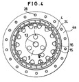
- Fig. 4 shows a side cross sectional view of the hub dynamo taken along the line A-A of Fig. 1.
- Firmly mounted inside the dynamo case 4 are four groups of magnets 24 each having seven magnetic poles constituting a part of the rotor.
- the stator of the hub dynamo includes the coil bobbins 15 and an iron core 16 both integrally mounted on the sleeve 9 by rivets 17.
- the sleeve is further fixed on the shaft 13, as previously described. Bores 27 formed along the periphery of the flange section 4a of the dynamo case 4 firmly receive spokes 2.
- the bicycle hub dynamo of the invention as described above may generate electric power by rotating the bicycle wheel on which the dynamo case is mounted, since the rotation of the wheel causes electromagnetic induction due to changes in magnetic fields through the magnetic circuits which are generated through the coils in the coil bobbins 15, the iron core 16, magnets 24, and the iron dynamo case 4.
- hub dynamo of the invention has an advantage that the bearings 5 are prevented from coming off the position during its assembly since the bearings 5 are firmly secured between the dynamo case 4 and the flange 3 while the bearings 19 are firmly fitted in the central recess of the dynamo case cap 23 by the sleeve 9.
- the stator and the rotor may be assembled independently, so that the assembly of the hub dynamo may be carried out in a simple manner.
- the hub dynamo is essentially enclosed except for the bearings, the hub dynamo is well protected against dust and has an increased durability.
- the dynamo case of the invention may be fabricated in a sequence of simple press works. It would be also appreciated that the dynamo case serves no only as a case of the dynamo but also as yokes for the magnetic circuits, so that the iron dynamo case of the invention helps reduce the number of elements involved in manufacturing the hub dynamo compared with conventional ones, which in turn allows production of economical bicycle hub dynamos.
Landscapes
- Engineering & Computer Science (AREA)
- Mechanical Engineering (AREA)
- Permanent Magnet Type Synchronous Machine (AREA)
- Connection Of Motors, Electrical Generators, Mechanical Devices, And The Like (AREA)
Abstract
Description
- This invention relates to an improvement in a hub dynamo for a bicycle.
- Recent years bicycle manufacturers have been confronted with competitions in manufacturing low-cost products, so that they have been attempting to reduce the number of optional items for a bicycle. However, a bicycle dynamo is indispensable for a bicycle for its safe driving, especially during night time. One common type of dynamos manufactured for this purpose is a hub dynamo.
- A hub dynamo for a bicycle (hereinafter referred to as bicycle hub dynamo or simply as hub dynamo) is a dynamo which is mounted on a hub of a bicycle, as described in for example Japanese Utility Model Publication No. 57-49584.
- This publication describes a hub dynamo having a structure as shown in Fig. 5, which we shall briefly discuss below for better understanding of a bicycle hub dynamo. A hub dynamo has
stator coils 48 which are mounted on ashaft 41 of a bicycle by aplate 47, and a rotor constituting ofmagnets 45 andyokes 46. Themagnets 45 and theyokes 46 are secured on analuminum hub drum 44, which drum is in turn fixed on ahub body 43. The stator (plate 47 and coils 48) and the rotor (hub body 43,hub drum 44,magnets 45 and yokes 46) are rotatably coupled with each other viabearings 42. - As seen in Fig. 5, these bearings are simply fitted in the opposite ends of the
hub body 43 to couple the stator with the rotor. Consequently, the bearings are likely to drop from thehub body 43 during assembly of theshaft 41 through the inner liners of thebearings 42 if the shaft abuts on the edges of inner liners. This causes a disadvantage that the assembly of the hub must be done very carefully, so that it is a time taking job and contributes to the cost of such hub dynamo. - This type of hub dynamos have another disadvantage that magnetic circuits formed in the hub dynamo are affected by dust which has infiltrated from a gap between the
plate 47 and thehub drum 44 and accumulated in thestator coil 48 over a long period of time, thereby weakening the magnetic flux through the coil and lowering the generating power of the hub dynamo. - The hub dynamo has a further disadvantage that the
aluminum hub drum 44 requires machining and grinding thereof after it is cast. In addition, thealuminum hub drum 44 requires iron yokes such as theyokes 46 inside thehub drum 44 for enhancing the magnetic flux through thestator coils 48. This disadvantageously add a further process and cost to the hub dynamo. - The invention is aimed to alleviate these prior art problems by providing an improved hub dynamo for bicycle which has a simple structure as well as good sealability against dust. Thus, the bicycle hub dynamo may be manufactured at a reduced cost and assembled in a simple manner.
- It is therefore an object of the invention to provide a bicycle hub dynamo having an iron dynamo case which may simultaneously substitute for a conventional aluminum dynamo case and conventional annular iron yokes forming a part of the magnetic circuits. Such iron dynamo case may be fabricated through a sequence of simple press works.
- Since use of such iron dynamo case reduces the number of elements of a hub dynamo, it allows reduction of material cost of the dynamo.
- It would be appreciated that such iron dynamo case manufactured in press works further contributes reduction of manufacturing cost of a bicycle hub dynamo, since it does not require processes such as casting, machining, grinding and/or coating with a paint as required for aluminum cases.
- A hub dynamo for bicycle of the invention comprises: a stator fixedly mounted on an immovable shaft; a rotor including a hub dynamo case, a flange secured on one end of the hub dynamo case, a hub dynamo case cap fitted in the hub dynamo case, and a multiplicity of magnets fixed on the inner wall of the hub dynamo case; a first set of bearings firmly fitted between the flange and the hub dynamo case; and a second set of bearings firmly fitted on the hub dynamo case cap, wherein the shaft is fitted in the first and second set of bearings so that the rotor is rotatably coupled with the stator.
- In this arrangement, it would be appreciated that the dynamo case is not only fixed on the flange but also the first bearings are secured between them, so that the bearings are prevented from dropping out of the position and that the shaft may be easily mounted on the bearings and secured by a nut. The same is true with the second set of bearings and the shaft since these bearings are also firmly held in the hub dynamo case cap. It would be also appreciated that the hub dynamo case may be fitted in the hub dynamo case such that it seals the hub dynamo.
- These and other features of the present invention may be more readily understood by reference to the following description, taken in conjunction with the accompanying drawings, in which:
- Fig. 1 is a cross sectional view of a hub dynamo for bicycle according to the invention, taken along the axis of the hub dynamo;
- Fig. 2 is an exploded cross sectional view of the hub dynamo shown in Fig. 1;
- Fig. 3 is a side view of the hub dynamo shown in Fig. 1, taken from the side thereof a having a flange.
- Fig. 4 is a side view of the hub dynamo taken along the line A-A of Fig. 1.
- Fig. 5 is a side cross sectional view of a conventional hub dynamo for bicycle.
- A cross section of a preferred embodiment of the hub dynamo of the present invention is shown in Fig. 1. An
iron flange 3 fabricated in the form of generally circular disk and having a central recess formed by press works is fixed on the ends of right spokes 1. Aniron dynamo case 4, which may be also fabricated by press works, is fixed on theleft spokes 2. - The central recess of the
flange 3 receivesbearings 5, which are forced therein. Theflange 3 is fixed on thedynamo case 4 byrivets 8 so that anouter liner 5a of thebearings 5 is secured in the recess and does not come off the position. Theinner liner 5b of thebearings 5 is forced on abearing section 9a of asleeve 9 which is made of aluminum by die casting insert molding to firmly fit on ashaft 13 of the bicycle. Thus, the sleeve is integral with theshaft 13. Theinner liner 5b is then secured by awasher 11 andnuts 12, so that it is in position between a large-diameter section 10 of thesleeve 9 and thewasher 11. Theintegral sleeve 9 may be made of a hard plastic molded on theshaft 13. - Secured on the outer surface of the
integral sleeve 9 by rivets arestator coils 14,coil bobbins 15, and aniron core 16 of the hub dynamo. Theinner liner 19b ofbearings 19 is forced on a bearing section of thesleeve 9. Theinner liner 19b is secured between a large-diameter section of thesleeve 19 and awasher 20 by anut 22. An insulating terminal member havingoutput terminals 21 for electrical connections with the hub dynamo is provided between thewasher 20 and thenut 22. - The
outer liner 19a of thebearings 19 is forced in the central recess of a generally cylindricaldynamo case cap 23. As seen from the Figure, the recess is formed inside a protruding section of adynamo case cap 23, which may be fabricated by press works. - The
dynamo case cap 23 also has a folded rim, which is fitted in the opening of thedynamo case 4. - The
dynamo case 4 and thedynamo case cap 23 constitutes the rotor of the hub dynamo. Fixedly secured inside thedynamo case 4 aremagnets 24. Theiron dynamo case 4 serves as yokes for the magnetic circuits generated by the magnets. - A pair of
forks 25 extending from the body of the bicycle are each fixed on theshaft 13 with a pair ofbolts 26. - Fig. 2 is an exploded cross section of the hub dynamo, illustrating the process of assembling the hub dynamo. As seen in the Fig. 2, in general the hub dynamo is assembled from a stator section and a rotor section.
- To be more specific, the
sleeve 9 is first molded on theshaft 13 at a predetermined position thereof so that they are integral with each other. The integral sleeve has bearingsections bearings diameter sections coils 14, thecoil bobbins 15 and theiron core 16 are then mounted on theintegral sleeve 9 by means ofrivets 17 to form the stator section of the dynamo. - Next, the
outer liner 19a of thebearings 19 is forced into the central recess of thedynamo case cap 23 and theinner liner 19b of thebearing 19 is mounted on thebearing section 9b of theintegral sleeve 9 until theinner liner 19b abuts on the large-diameter section 18 of thesleeve 9. Thenut 22 is then threaded on theshaft 13 to secure thebearing 19 in position, with awasher 20 and an insulating terminalplate having terminals 21 inserted between thenut 22 and the large-diameter section 18. - With this
nut 22 thus threaded on theshaft 13, theinner liner 19b and thesleeve 9 are firmly fixed on theshaft 13 together, forming the integral stator section. - The
dynamo case 4 of the rotor may be fabricated by deep drawing an iron plate through repeated press works to form a cylindrical protrusion at the center of thedynamo case 4. The protrusion provides inside thereof a recess for firmly receiving themagnets 24. Thus, themagnets 24 are fixed on the inner surface of the recess. It would be appreciated that this fabrication of thedynamo case 4 through press works needs no further machining or grinding, and greatly reduces the number of manufacturing processes as required for the prior art aluminum dynamo case, thereby reducing cost of the dynamo. - Next, the
outer liner 5a of thebearing 5 is inserted in the central recess of theflange 3, until thedynamo case 4 abuts on theflange 3 and firmly hold theouter liner 5a in the recess. Thedynamo case 4 is then fixed on the flange byrivets 8. This results in the rotor section (the right member shown in Fig. 2), which is a major portion of the rotor. - The left member shown in Fig. 2 is then coupled with the right member such that the
bearing section 9a of theintegral sleeve 9 of the stator is forced into theinner liner 5b of thebearing 5 until the large-diameter section 10 of thesleeve 9 abuts on theinner liner 5b of thebearing 5, and then secured with theinner liner 5b by tightening the nuts 12 on theshaft 13 via thewasher 11. It should be noted that in this process thedynamo case cap 23 is fitted in the opening of thedynamo case 4 of the rotor, thereby forming the complete rotor. This coupling of the two members results in a complete hub dynamo as shown in Fig. 1. - Fig. 3 shows a side view of the hub dynamo thus assembled, taken from the side of the
flange 3. As seen in the Figure, theflange 3 is fixed on thedynamo case 4 byrivets 8 as well as on theshaft 13 by nuts 12. The bores 27 formed in theflange 3 receive the spokes 1. - Fig. 4 shows a side cross sectional view of the hub dynamo taken along the line A-A of Fig. 1. Firmly mounted inside the
dynamo case 4 are four groups ofmagnets 24 each having seven magnetic poles constituting a part of the rotor. The stator of the hub dynamo includes thecoil bobbins 15 and aniron core 16 both integrally mounted on thesleeve 9 byrivets 17. The sleeve is further fixed on theshaft 13, as previously described.Bores 27 formed along the periphery of theflange section 4a of thedynamo case 4 firmly receivespokes 2. - In operation, the bicycle hub dynamo of the invention as described above may generate electric power by rotating the bicycle wheel on which the dynamo case is mounted, since the rotation of the wheel causes electromagnetic induction due to changes in magnetic fields through the magnetic circuits which are generated through the coils in the
coil bobbins 15, theiron core 16,magnets 24, and theiron dynamo case 4. - In summary, hub dynamo of the invention has an advantage that the
bearings 5 are prevented from coming off the position during its assembly since thebearings 5 are firmly secured between thedynamo case 4 and theflange 3 while thebearings 19 are firmly fitted in the central recess of thedynamo case cap 23 by thesleeve 9. In addition, the stator and the rotor may be assembled independently, so that the assembly of the hub dynamo may be carried out in a simple manner. Furthermore, since the hub dynamo is essentially enclosed except for the bearings, the hub dynamo is well protected against dust and has an increased durability. - It would be appreciated that the dynamo case of the invention may be fabricated in a sequence of simple press works. It would be also appreciated that the dynamo case serves no only as a case of the dynamo but also as yokes for the magnetic circuits, so that the iron dynamo case of the invention helps reduce the number of elements involved in manufacturing the hub dynamo compared with conventional ones, which in turn allows production of economical bicycle hub dynamos.
Claims (4)
- A hub dynamo constructed inside a hub of a bicycle, comprising:an iron case serving as a dynamo case as well as yokes of magnetic circuits of said hub dynamo.
- A hub dynamo constructed inside a hub of a bicycle, comprising:a stator fixedly mounted on a shaft of said bicycle;a rotor includinga hub dynamo case made of iron and having an opening at one end thereof,a flange having a central recess and secured on the other end of said hub dynamo case,a hub dynamo case cap having a central recess and fitted in said opening of said hub dynamo case, anda multiplicity of magnets fixed on the inner wall of said hub dynamo case;a first set of bearings firmly fitted in said recess of said flange and firmly held between said flange and said hub dynamo case; anda second set of bearings firmly fitted in said recess of said hub dynamo case cap , whereinsaid shaft is fitted in said first and second sets of bearings so that said rotor is rotatably coupled with said stator.
- The hub dynamo according to claim 2, wherein said dynamo case is fabricated by deep drawing in press works.
- The hub dynamo according to claim 2, whereinsaid shaft is provided with a sleeve which has on the surface thereof stator coils, and has opposite ends abutting on said first and second bearings, respectively; andsaid first and second bearings are fixed on said sleeves by nuts tightened from the opposite ends of said sleeves, respectively.
Applications Claiming Priority (6)
| Application Number | Priority Date | Filing Date | Title |
|---|---|---|---|
| JP31587695 | 1995-11-10 | ||
| JP315876/95 | 1995-11-10 | ||
| JP31587795A JP3272224B2 (en) | 1995-11-10 | 1995-11-10 | Bicycle hub dynamo |
| JP315877/95 | 1995-11-10 | ||
| JP31587695A JPH09132185A (en) | 1995-11-10 | 1995-11-10 | Hub dynamo for bicycle |
| JP31587795 | 1995-11-10 |
Publications (3)
| Publication Number | Publication Date |
|---|---|
| EP0773157A2 true EP0773157A2 (en) | 1997-05-14 |
| EP0773157A3 EP0773157A3 (en) | 1998-06-03 |
| EP0773157B1 EP0773157B1 (en) | 2004-02-04 |
Family
ID=26568459
Family Applications (1)
| Application Number | Title | Priority Date | Filing Date |
|---|---|---|---|
| EP96117855A Expired - Lifetime EP0773157B1 (en) | 1995-11-10 | 1996-11-07 | Hub dynamo for bicycle |
Country Status (3)
| Country | Link |
|---|---|
| EP (1) | EP0773157B1 (en) |
| CN (1) | CN1105051C (en) |
| DE (1) | DE69631461T2 (en) |
Cited By (3)
| Publication number | Priority date | Publication date | Assignee | Title |
|---|---|---|---|---|
| US6659895B2 (en) | 1998-12-18 | 2003-12-09 | Shimano, Inc. | Motion sensor for use with a bicycle sprocket assembly |
| EP1270389A3 (en) * | 2001-06-21 | 2004-03-31 | Sanyo Electric Co. Ltd | Bicycle hub dynamo |
| GB2427078A (en) * | 2005-06-10 | 2006-12-13 | Yi-Yin Lin | Small generator with collective multiple magnetic poles |
Families Citing this family (4)
| Publication number | Priority date | Publication date | Assignee | Title |
|---|---|---|---|---|
| WO2003033333A1 (en) * | 2001-10-16 | 2003-04-24 | Pao-Chuang Hung | Wheel auto-power generator and a lamp body used therein |
| JP4221382B2 (en) * | 2005-01-24 | 2009-02-12 | 株式会社シマノ | Adapter for power generation hub |
| AT512298B1 (en) * | 2012-02-06 | 2013-07-15 | Innova Patent Gmbh | ROLE, IN PARTICULAR ROLLER BZW. CARRIER FOR RAILWAY SYSTEMS |
| JP6928443B2 (en) * | 2016-12-16 | 2021-09-01 | 株式会社シマノ | Bicycle hub |
Citations (1)
| Publication number | Priority date | Publication date | Assignee | Title |
|---|---|---|---|---|
| JPS5749584U (en) | 1980-09-05 | 1982-03-19 |
Family Cites Families (5)
| Publication number | Priority date | Publication date | Assignee | Title |
|---|---|---|---|---|
| SE436412B (en) * | 1983-05-04 | 1984-12-10 | Nilsson Ingvar Mek Ab | MANUAL DEVICE FOR A NAV CONNECTED GENERATOR MANOVER DEVICE FOR A NAV CONNECTED GENERATOR |
| JPH0123900Y2 (en) * | 1984-11-08 | 1989-07-20 | ||
| DE9103070U1 (en) * | 1990-10-10 | 1991-07-18 | Metzner, Stefan E., 8900 Augsburg | Electric dynamo for bicycles mounted on the axle or hub of a wheel |
| DE4232182A1 (en) * | 1992-09-25 | 1994-03-31 | Wilfried Schmidt | Hub generator, in particular for bicycles |
| JP3561527B2 (en) * | 1994-04-27 | 2004-09-02 | 三洋電機株式会社 | Dynamo for bicycle |
-
1996
- 1996-11-07 EP EP96117855A patent/EP0773157B1/en not_active Expired - Lifetime
- 1996-11-07 DE DE69631461T patent/DE69631461T2/en not_active Expired - Fee Related
- 1996-11-09 CN CN96118993A patent/CN1105051C/en not_active Expired - Fee Related
Patent Citations (1)
| Publication number | Priority date | Publication date | Assignee | Title |
|---|---|---|---|---|
| JPS5749584U (en) | 1980-09-05 | 1982-03-19 |
Cited By (8)
| Publication number | Priority date | Publication date | Assignee | Title |
|---|---|---|---|---|
| US6659895B2 (en) | 1998-12-18 | 2003-12-09 | Shimano, Inc. | Motion sensor for use with a bicycle sprocket assembly |
| US6676549B1 (en) * | 1998-12-18 | 2004-01-13 | Shimano, Inc. | Motion sensor for use with a bicycle sprocket assembly |
| US6761655B2 (en) | 1998-12-18 | 2004-07-13 | Shimano, Inc. | Motion sensor for use with a bicycle sprocket assembly |
| US7001294B2 (en) | 1998-12-18 | 2006-02-21 | Shimano, Inc. | Method of using a motion sensor with a bicycle sprocket assembly |
| US7004862B2 (en) | 1998-12-18 | 2006-02-28 | Masahiko Fukuda | Method of using a motion sensor with a bicycle sprocket assembly |
| EP1270389A3 (en) * | 2001-06-21 | 2004-03-31 | Sanyo Electric Co. Ltd | Bicycle hub dynamo |
| GB2427078A (en) * | 2005-06-10 | 2006-12-13 | Yi-Yin Lin | Small generator with collective multiple magnetic poles |
| GB2427078B (en) * | 2005-06-10 | 2009-04-01 | Yi-Yin Lin | Small generator with collective multiple magnetic poles |
Also Published As
| Publication number | Publication date |
|---|---|
| DE69631461D1 (en) | 2004-03-11 |
| EP0773157B1 (en) | 2004-02-04 |
| CN1154319A (en) | 1997-07-16 |
| DE69631461T2 (en) | 2004-09-16 |
| CN1105051C (en) | 2003-04-09 |
| EP0773157A3 (en) | 1998-06-03 |
Similar Documents
| Publication | Publication Date | Title |
|---|---|---|
| US7423357B2 (en) | Electric rotating machine | |
| US6008559A (en) | Motor using a rotor including an interior permanent magnet | |
| US7323801B2 (en) | Axial air-gap electronic motor | |
| US5646467A (en) | Axial airgap DC motor | |
| US5973435A (en) | Rotary electric machine having auxiliary permanent magnets | |
| US4625392A (en) | Method of manufacturing a molded rotatable assembly for dynamoelectric machines | |
| US8278789B2 (en) | Bicycle generator hub | |
| US7148598B2 (en) | Spoke permanent magnet rotors for electrical machines and methods of manufacturing same | |
| US6046518A (en) | Axial gap electrical machine | |
| US7638913B2 (en) | Rotor core with spacers | |
| EP1050946A2 (en) | Composite stator and rotor for an electric motor | |
| US20200403469A1 (en) | Electric motor | |
| NZ537718A (en) | Rotor for permanent magnet motor of outer rotor type | |
| JPH09508520A (en) | Motor including permanent magnet rotor | |
| JP2003333777A (en) | Claw-pole generator and hub dynamo for bicycle | |
| US20040155550A1 (en) | Armature having teeth | |
| JP4720278B2 (en) | Axial air gap type electric motor | |
| JP4027059B2 (en) | Bicycle hub dynamo | |
| EP0773157B1 (en) | Hub dynamo for bicycle | |
| US11296561B2 (en) | Motor for ceiling fan | |
| JP3272224B2 (en) | Bicycle hub dynamo | |
| JPH08168226A (en) | Motor with reduction gear | |
| JP2000116082A (en) | Outer periphery drive electric motor | |
| JPH09132185A (en) | Hub dynamo for bicycle | |
| CN217824474U (en) | Outer rotor and motor applying same |
Legal Events
| Date | Code | Title | Description |
|---|---|---|---|
| PUAI | Public reference made under article 153(3) epc to a published international application that has entered the european phase |
Free format text: ORIGINAL CODE: 0009012 |
|
| AK | Designated contracting states |
Kind code of ref document: A2 Designated state(s): CH DE FR GB IT LI NL |
|
| PUAL | Search report despatched |
Free format text: ORIGINAL CODE: 0009013 |
|
| AK | Designated contracting states |
Kind code of ref document: A3 Designated state(s): CH DE FR GB IT LI NL |
|
| 17P | Request for examination filed |
Effective date: 19980629 |
|
| 17Q | First examination report despatched |
Effective date: 20000809 |
|
| GRAH | Despatch of communication of intention to grant a patent |
Free format text: ORIGINAL CODE: EPIDOS IGRA |
|
| GRAS | Grant fee paid |
Free format text: ORIGINAL CODE: EPIDOSNIGR3 |
|
| GRAA | (expected) grant |
Free format text: ORIGINAL CODE: 0009210 |
|
| AK | Designated contracting states |
Kind code of ref document: B1 Designated state(s): CH DE FR GB IT LI NL |
|
| PG25 | Lapsed in a contracting state [announced via postgrant information from national office to epo] |
Ref country code: LI Free format text: LAPSE BECAUSE OF FAILURE TO SUBMIT A TRANSLATION OF THE DESCRIPTION OR TO PAY THE FEE WITHIN THE PRESCRIBED TIME-LIMIT Effective date: 20040204 Ref country code: CH Free format text: LAPSE BECAUSE OF FAILURE TO SUBMIT A TRANSLATION OF THE DESCRIPTION OR TO PAY THE FEE WITHIN THE PRESCRIBED TIME-LIMIT Effective date: 20040204 |
|
| REG | Reference to a national code |
Ref country code: GB Ref legal event code: FG4D |
|
| REG | Reference to a national code |
Ref country code: CH Ref legal event code: EP |
|
| REF | Corresponds to: |
Ref document number: 69631461 Country of ref document: DE Date of ref document: 20040311 Kind code of ref document: P |
|
| REG | Reference to a national code |
Ref country code: CH Ref legal event code: PL |
|
| ET | Fr: translation filed | ||
| PLBE | No opposition filed within time limit |
Free format text: ORIGINAL CODE: 0009261 |
|
| STAA | Information on the status of an ep patent application or granted ep patent |
Free format text: STATUS: NO OPPOSITION FILED WITHIN TIME LIMIT |
|
| 26N | No opposition filed |
Effective date: 20041105 |
|
| PGFP | Annual fee paid to national office [announced via postgrant information from national office to epo] |
Ref country code: FR Payment date: 20051108 Year of fee payment: 10 |
|
| PGFP | Annual fee paid to national office [announced via postgrant information from national office to epo] |
Ref country code: IT Payment date: 20061130 Year of fee payment: 11 |
|
| REG | Reference to a national code |
Ref country code: FR Ref legal event code: ST Effective date: 20070731 |
|
| PGFP | Annual fee paid to national office [announced via postgrant information from national office to epo] |
Ref country code: NL Payment date: 20071115 Year of fee payment: 12 Ref country code: DE Payment date: 20071101 Year of fee payment: 12 |
|
| PG25 | Lapsed in a contracting state [announced via postgrant information from national office to epo] |
Ref country code: FR Free format text: LAPSE BECAUSE OF NON-PAYMENT OF DUE FEES Effective date: 20061130 |
|
| PGFP | Annual fee paid to national office [announced via postgrant information from national office to epo] |
Ref country code: GB Payment date: 20071107 Year of fee payment: 12 |
|
| GBPC | Gb: european patent ceased through non-payment of renewal fee |
Effective date: 20081107 |
|
| PG25 | Lapsed in a contracting state [announced via postgrant information from national office to epo] |
Ref country code: NL Free format text: LAPSE BECAUSE OF NON-PAYMENT OF DUE FEES Effective date: 20090601 |
|
| NLV4 | Nl: lapsed or anulled due to non-payment of the annual fee |
Effective date: 20090601 |
|
| PG25 | Lapsed in a contracting state [announced via postgrant information from national office to epo] |
Ref country code: IT Free format text: LAPSE BECAUSE OF NON-PAYMENT OF DUE FEES Effective date: 20071107 |
|
| PG25 | Lapsed in a contracting state [announced via postgrant information from national office to epo] |
Ref country code: DE Free format text: LAPSE BECAUSE OF NON-PAYMENT OF DUE FEES Effective date: 20090603 |
|
| PG25 | Lapsed in a contracting state [announced via postgrant information from national office to epo] |
Ref country code: GB Free format text: LAPSE BECAUSE OF NON-PAYMENT OF DUE FEES Effective date: 20081107 |