EP0772271A2 - A cable duct - Google Patents
A cable duct Download PDFInfo
- Publication number
- EP0772271A2 EP0772271A2 EP96650049A EP96650049A EP0772271A2 EP 0772271 A2 EP0772271 A2 EP 0772271A2 EP 96650049 A EP96650049 A EP 96650049A EP 96650049 A EP96650049 A EP 96650049A EP 0772271 A2 EP0772271 A2 EP 0772271A2
- Authority
- EP
- European Patent Office
- Prior art keywords
- duct
- ducts
- cable duct
- cover
- finger
- Prior art date
- Legal status (The legal status is an assumption and is not a legal conclusion. Google has not performed a legal analysis and makes no representation as to the accuracy of the status listed.)
- Granted
Links
Images


Classifications
-
- H—ELECTRICITY
- H02—GENERATION; CONVERSION OR DISTRIBUTION OF ELECTRIC POWER
- H02G—INSTALLATION OF ELECTRIC CABLES OR LINES, OR OF COMBINED OPTICAL AND ELECTRIC CABLES OR LINES
- H02G3/00—Installations of electric cables or lines or protective tubing therefor in or on buildings, equivalent structures or vehicles
- H02G3/02—Details
- H02G3/06—Joints for connecting lengths of protective tubing or channels, to each other or to casings, e.g. to distribution boxes; Ensuring electrical continuity in the joint
- H02G3/0608—Joints for connecting non cylindrical conduits, e.g. channels
Definitions
- This invention relates to a cable duct.
- the invention particularly relates to a cable duct for use in the installation of track-side signalling, fibre optic and telecommunications cable systems for railway and light railway projects.
- Cable ducts in precast concrete material are widely used for housing cabling alongside railway tracks.
- the inherent weight of concrete ducts makes them relatively difficult and cumbersome to handle and time consuming to lay.
- the present invention is directed towards overcoming this problem and providing an improved cable duct.
- a cable duct having a base with upstanding side walls at opposite sides of the base forming with the base an open ended channel for reception of cables, and means at each end of the duct for interlocking the duct with another duct end to end to form an extended channel for cables or the like.
- the duct is formed of a structural foam plastics material resulting in a light weight duct of good strength.
- the duct can be laid in a relatively easy and rapid fashion.
- means is provided to prevent relative vertical movement between a pair of interlocked ducts.
- said means comprises complementary interengagable formations at each end of the duct which engage when a pair of ducts are interlocked.
- expansion means is provided to facilitate the longitudinal expansion of adjacent ducts when interlocked end to end.
- the expansion means comprises at each end of the duct a curved flange on one side wall and an associated curved housing on the other side wall, the flange of one duct being rotatable engagable within the housing on an adjacent duct when interlocking the ducts.
- mounting means is provided on the duct for mounting the duct on one or more support posts.
- the mounting means comprises one or more post- engaging sockets on the duct.
- each socket is vertically disposed on a side wall of the duct having a downwardly open inlet.
- an outwardly extending shoe is provided at a lower end of each side wall for keying the duct into a foundation material.
- an upper face of the shoe slopes upwardly and outwardly from the side wall.
- a number of spaced-apart upstanding ribs are provided extending outwardly from each side wall and upwardly from the shoe.
- the duct interlocking means is releasably inter-engagable with a complementary interlocking means on another duct.
- the interlocking means comprises a curved finger at each end of the duct, each finger for hooking engagement with a complementary finger on another duct.
- means is provided to prevent relative vertical movement between a pair of interlocked ducts.
- said means comprises a tongue associated with each finger, the tongue spaced-apart from the finger and vertically displaced relative to the finger so that when a pair of fingers interlock a tongue associated with one of the fingers engages beneath the other finger.
- the duct interlocking means is of two-part construction comprising a male connector which is releasably engagable with a complimentary female receiver, one of said parts being provided at each end of the duct.
- the male part comprises a bulbus head connected to the base by a narrow neck and the female receiver comprises a re-entrant slot in the base.
- the means to prevent relative vertical movement between a pair of interlocked ducts comprises complimentary inter-engagable formations on the male and female parts.
- a number of spaced-apart upstanding ribs are provided extending outwardly from each side wall and upwardly from the shoe. These ribs advantageously provide strengthening and also assist in the positive location of the duct within a foundation material resisting movement of the duct within the foundation material.
- the side walls are of hollow construction comprising inner and outer walls interconnected by internal ribs.
- the ribs strengthen the side walls and also facilitate the flow of plastics material in a mould when forming the duct.
- hanger means is provided on the duct for suspending the duct on a wall, embankment or the like.
- the duct has a number of spaced-apart knock-out panels, each panel being removable for through passage of cables into or out of the duct.
- the base has a water drain channel in a top surface of the base.
- the water drain channel extends between opposite ends of the base.
- a shoulder is formed at a top end of each side wall for reception of a cover engagable between the side walls to close the duct.
- the shoulder has an outwardly and downwardly sloping upper surface to facilitate water run-off.
- a hinge mount is formed at an upper end of one or both side walls for hingedly mounting the cover on the side walls.
- the hinge mount is integrally formed with the post mounting means.
- the cover has a top with a downwardly depending peripheral rim and ribs on an underside of the top located within the rim.
- a top surface of the cover has an anti-slip surface.
- the anti-slip surface is preferably formed by a plurality of upstanding spaced-apart projections on the top surface.
- one or more water drainage slots are provided at an edge of the top surface.
- one or more hinge pins are provided at an edge of the cover for engagement with the hinge mount on the duct.
- locking means may be provided for releasably securing the cover on the duct.
- the expansion means comprises complimentary inter-engagable formations at each end of the duct, the formations projecting outwardly of at least one end of the duct so that the associated formations on a pair of ducts overlap upon interlocking of said ducts to prevent ingress of material into the ducts, the cover for the duct also being provided with overlapping expansion formations at each end of the cover for overlapping engagement with adjacent covers.
- the invention provides an interlocking device for ducts as herein described.
- a cable duct according to the invention indicated generally by the reference numeral 1.
- the duct 1 is formed from plastics material using a structural foam injection moulding process which incorporates injecting nitrogen gas into the melt at the moulding stage. This results in an aerated bubble/honeycomb structure in the wall section which combines light weight and high strength in the duct.
- the duct 1 has a base 2 with upstanding side walls 3 at opposite sides of the base 2 forming with the base 2 an open ended channel for reception of cables.
- a duct interlocking device 5 is provided at each end of the duct 1 at the base 2 for interlocking the duct 1 with another duct 1 end to end to form an extended channel for cables.
- the interlocking device 5 comprises a curved finger 6, each finger 6 for hooking engagement with a complementary finger 6 on another duct 1 as shown in Fig. 2.
- a curved slot 7 behind each finger 6 receives another finger 6 for hooking engagement of the fingers 6 as shown in Fig. 2.
- a tongue 8 is associated with each finger 6.
- the tongue 8 is spaced-apart from the finger 6 within the slot 7 and vertically displaced below the finger 6 so that when a pair of fingers 6 interlock, a tongue 8 associated with one of the fingers 6 engages beneath the other finger 6. This advantageously resists any vertical displacement of a duct 1 relative to an adjacent interlocked duct thus preventing a trip hazard.
- the interlocking device 5 allows semi-automatic and automatic installation of ducts 1. Further, the design of the interlocking device 5 is such that it allows 3° movement side to side. This advantageously facilitates gently curving a run of ducts 1 around a bend for example.
- Each side wall 3 is of hollow construction comprising an inner wall 15 and an outer wall 16 spaced-apart from the inner wall 15. Internal ribs extend between the inner and outer walls 15, 16. Each side wall 3 is open at its lower end. A shoulder 17 extends between an upper end of the inner and outer walls 15, 16. It will be noted that the shoulder 17 is sloped outwardly and downwardly between the inner wall 15 and the outer wall 16 for water run-off. Upstanding flanges 19 form an extension of the inner walls 15 for positive location of a cover 20 on the shoulders 17 to close the duct 1.
- Each shoe 22 has an upper surface 23 which slopes upwardly and outwardly of the side wall 3 to facilitate keying the duct 1 into a foundation material, particularly where the foundation material is fine soil.
- External ribs 25 are also provided spaced-apart along each outer wall 16 extending upwardly from the shoe 22 to assist in firmly bedding the duct 1 in a foundation material.
- a pair of vertically disposed housings 30 are provided spaced-apart on an outside of each side wall 3. Each housing 30 forms a downwardly open socket for mounting the duct 1 on support posts 32 if desired as shown in Fig. 5.
- a slot 34 is provided adjacent an upper end of each housing 30 for engagement by a clip, if desired, to hang the duct 1 in tunnels for example. It will be noted that each housing 30 projects above the outer wall 16 to provide with the flanges 19 for positive location of the cover 20 on the duct 1.
- Slots 36 are provided at an upper end of each housing 30 for engagement with hinge pins 37 on the cover 20 to allow hinging of the cover 20 on either side wall 3, if desired.
- FIG. 6 to 21 there is shown another cable duct 40 which is largely similar to the cable duct previously described with reference to Figs. 1 to 5 and like parts are assigned the same reference numerals.
- a number of knock-out panels 41 are provided in the side walls 3 and base 2 to allow cable entry and exit.
- a number of upstanding ribs 42 are provided beneath the base 2 extending between opposite sides of the duct 1 to provide strength and, as can be seen in Fig. 8, the underside of the duct 1 is of generally box section.
- the box section and ribbing allows the duct to bite into track-side ballast and soils. Further, the ribbing allows the mould for forming the duct 1 to readily and quickly fill during the moulding process.
- Central slots 45 (Fig. 6) are provided in the base 2 for reception of an upstanding divider panel 46 and to allow drainage.
- Expansion means 50 is provided at each end of the duct to accommodate longitudinal expansion and contraction of the duct comprising a curved flange 51 on one side and an associated curved housing 52 on the other side. As shown in Fig. 11 a pair of ducts 40 rotatably engage to interlock associated flanges 51 and housings 52 of adjacent ducts 40.
- the expansion means 50 allows up to 6 mm longitudinal expansion of the duct to be absorbed.
- the cover 20 has a generally flat top 60 with a peripheral rim 61 which projects slightly above the top 60 and extends downwardly of the top 60. Ribs 62 extend downwardly from an inner surface of the top 60 within the rim 61. These ribs 62 ensure high strength and loading capability and ease the flow of material within the mould during the moulding process for forming the cover 20.
- the top 60 is provided with a number of upstanding spaced-apart projections 64 which provide an anti-slip surface.
- a plurality of water drainage slots 65 are provided in the rim 61 to prevent water or frost build-up on the cover which would provide a slip hazard.
- Expansion means for the cover 20 comprises an outwardly projecting tongue 63 at one end of the cover 20 and an associated socket 69 at the opposite end of the cover 20. On interlocked ducts the tongues 63 and sockets 69 of adjacent covers 20 overlap to prevent ingress of dirt.
- a standard cover 20 or a locking cover 70 may be provided for the ducts 1,40.
- the locking cover 70 has a slot 71 extending through a neck portion 72 between the projections 67 for reception of a locking plate 74, outer ends of which engage complementary slots 75 at an upper end of the housing 30 on the duct 1,40.
- Locking bolts 77 extend through associated holes 78 in the neck portion 72 to engage the locking plates 74 to secure the cover 70 on the duct 1,40.
- a T-junction 80 of similar construction to the duct 1,40 is shown which allows various bending radii of telecommunications and fibre optic cables to be accommodated.
- the interlocking means comprises a male connector 91 at one end of the duct 90 and a complementary female receiver 92 at the opposite end of the duct 90.
- the male connector 91 has a bulbous head 93.
- a narrowed neck portion 94 connects the bulbous head 93 to the base 2.
- the female receiver 92 comprises a re-entrant slot having an inner portion 95 for reception of the bulbous head 93 and a narrowed mouth 96 defined by pillars 97 which engage behind the bulbous head 93 with the neck 94.
- a pair of ducts 90 can be interlocked by engaging the bulbous head 93 of one duct 90 within the enlarged inner portion 95 of the female receiver 92.
- the width of the bulbous head 93 is somewhat smaller than the depth of the inner portion 93 and the neck 94 is somewhat deeper than the pillars 97 to allow for expansion and contraction of the ducts.
- Complementary inter-engagable formations are provided on the male connector 91 and the female receiver 92 to prevent relative vertical displacement of a pair of interconnected ducts 90.
- the formations comprise a pair of outwardly extending lugs 98 on opposite sides of the bulbous head 93 at a bottom of the bulbous head 93. These lugs 98 are engagable with associated slots 99 provided at each side of the inner portion 95 of the female receiver 92.
- wings 100 are provided at an upper end of the neck 94 for engagement with associated stepped grooves 101 at an upper end of each pillar 97.
- a plurality of the ducts 1,40,90 can be laid end to end alongside a track, the ducts interlocking to form a continuous channel for cables.
- the ducts 1,40,90 can be buried in track-side ballast, the interlocking devices 5 preventing unauthorised dismantling of the channel formed by the ducts 1,40,90 by vandals.
- any suitable locking means may be provided for releasably locking the cover on the duct.
- the ducts may be also used for housing pipework or the like.
Abstract
Description
- This invention relates to a cable duct.
- The invention particularly relates to a cable duct for use in the installation of track-side signalling, fibre optic and telecommunications cable systems for railway and light railway projects.
- Cable ducts in precast concrete material are widely used for housing cabling alongside railway tracks. The inherent weight of concrete ducts makes them relatively difficult and cumbersome to handle and time consuming to lay.
- The present invention is directed towards overcoming this problem and providing an improved cable duct.
- According to the invention, there is provided a cable duct having a base with upstanding side walls at opposite sides of the base forming with the base an open ended channel for reception of cables, and means at each end of the duct for interlocking the duct with another duct end to end to form an extended channel for cables or the like. Preferably, the duct is formed of a structural foam plastics material resulting in a light weight duct of good strength. Thus advantageously, the duct can be laid in a relatively easy and rapid fashion.
- In one embodiment means is provided to prevent relative vertical movement between a pair of interlocked ducts. Conveniently said means comprises complementary interengagable formations at each end of the duct which engage when a pair of ducts are interlocked.
- In another embodiment, expansion means is provided to facilitate the longitudinal expansion of adjacent ducts when interlocked end to end.
- Conveniently the expansion means comprises at each end of the duct a curved flange on one side wall and an associated curved housing on the other side wall, the flange of one duct being rotatable engagable within the housing on an adjacent duct when interlocking the ducts.
- In a further embodiment, mounting means is provided on the duct for mounting the duct on one or more support posts.
- Preferably the mounting means comprises one or more post- engaging sockets on the duct. Conveniently each socket is vertically disposed on a side wall of the duct having a downwardly open inlet.
- In a further embodiment an outwardly extending shoe is provided at a lower end of each side wall for keying the duct into a foundation material. Preferably an upper face of the shoe slopes upwardly and outwardly from the side wall.
- In another embodiment a number of spaced-apart upstanding ribs are provided extending outwardly from each side wall and upwardly from the shoe.
- In another embodiment, the duct interlocking means is releasably inter-engagable with a complementary interlocking means on another duct.
- In a particularly preferred embodiment, the interlocking means comprises a curved finger at each end of the duct, each finger for hooking engagement with a complementary finger on another duct.
- Preferably, means is provided to prevent relative vertical movement between a pair of interlocked ducts. Conveniently, said means comprises a tongue associated with each finger, the tongue spaced-apart from the finger and vertically displaced relative to the finger so that when a pair of fingers interlock a tongue associated with one of the fingers engages beneath the other finger.
- In another embodiment the duct interlocking means is of two-part construction comprising a male connector which is releasably engagable with a complimentary female receiver, one of said parts being provided at each end of the duct.
- Conveniently, the male part comprises a bulbus head connected to the base by a narrow neck and the female receiver comprises a re-entrant slot in the base.
- In another embodiment the means to prevent relative vertical movement between a pair of interlocked ducts comprises complimentary inter-engagable formations on the male and female parts.
- Preferably, a number of spaced-apart upstanding ribs are provided extending outwardly from each side wall and upwardly from the shoe. These ribs advantageously provide strengthening and also assist in the positive location of the duct within a foundation material resisting movement of the duct within the foundation material.
- In another embodiment, the side walls are of hollow construction comprising inner and outer walls interconnected by internal ribs. The ribs strengthen the side walls and also facilitate the flow of plastics material in a mould when forming the duct.
- In a further embodiment, hanger means is provided on the duct for suspending the duct on a wall, embankment or the like.
- Conveniently, the duct has a number of spaced-apart knock-out panels, each panel being removable for through passage of cables into or out of the duct.
- In a preferred embodiment, the base has a water drain channel in a top surface of the base. Preferably, the water drain channel extends between opposite ends of the base.
- In another embodiment, a shoulder is formed at a top end of each side wall for reception of a cover engagable between the side walls to close the duct.
- In a particularly preferred embodiment, the shoulder has an outwardly and downwardly sloping upper surface to facilitate water run-off.
- In a further embodiment, a hinge mount is formed at an upper end of one or both side walls for hingedly mounting the cover on the side walls. Conveniently, the hinge mount is integrally formed with the post mounting means.
- In another embodiment, the cover has a top with a downwardly depending peripheral rim and ribs on an underside of the top located within the rim.
- Preferably, a top surface of the cover has an anti-slip surface. The anti-slip surface is preferably formed by a plurality of upstanding spaced-apart projections on the top surface.
- In a particularly preferred embodiment, one or more water drainage slots are provided at an edge of the top surface.
- In another embodiment, one or more hinge pins are provided at an edge of the cover for engagement with the hinge mount on the duct.
- If desired, locking means may be provided for releasably securing the cover on the duct.
- In another embodiment the expansion means comprises complimentary inter-engagable formations at each end of the duct, the formations projecting outwardly of at least one end of the duct so that the associated formations on a pair of ducts overlap upon interlocking of said ducts to prevent ingress of material into the ducts, the cover for the duct also being provided with overlapping expansion formations at each end of the cover for overlapping engagement with adjacent covers.
- In another aspect, the invention provides an interlocking device for ducts as herein described.
- The invention will be more clearly understood by the following description of some embodiments thereof, given by way of example only, with reference to the accompanying drawings, in which:-
- Fig. 1 is an exploded perspective view of a cable duct according to the invention;
- Fig. 2 is a detail perspective view showing one end of the duct;
- Fig. 3 is a detail perspective view showing an end of the duct;
- Fig. 4 is a detail plan view showing the end of the duct;
- Fig. 5 is a perspective view of the duct shown mounted on support posts;
- Fig. 6 is a plan view of another duct;
- Fig. 7 is an elevational view of a divider panel for use with the duct of Fig. 6;
- Fig. 8 is an underneath plan view of the duct of Fig. 6;
- Fig. 9 is a partially sectioned elevational view of the duct of Fig. 6;
- Fig. 10 is an end elevational view of the duct of Fig. 6;
- Fig. 11 is an end elevational view of the duct of Fig. 6 illustrating interconnection of a pair of ducts;
- Fig. 12 is a sectional view taken along the line XII-XII of Fig. 6;
- Fig. 13 is a sectional view taken along the line XIII-XIII of Fig. 6;
- Fig. 14 is a detail sectional view taken along the line XIV-XIV of Fig. 6;
- Fig. 15 is a plan view of a cover for the ducts;
- Fig. 16 is an end elevational view of the cover;
- Fig. 17 is a side, partially sectioned, elevational view of the cover;
- Fig. 18 is an underneath plan view of the cover;
- Fig. 19 is a sectional view taken along the line XIX-XIX of Fig. 18;
- Fig. 20 is a sectional view taken along the line XX-XX of Fig. 18;
- Fig. 21 is a sectional view taken along the line XXI-XXI of Fig. 18;
- Fig. 22 is an exploded perspective view of another duct;
- Fig. 23 is a perspective view of a T-junction duct according to the invention;
- Fig. 24 is a plan view of another duct;
- Fig. 25 is an underneath plan view of the duct of Fig. 24;
- Fig. 26 is a sectional view taken along the line XXVI-XXVI of Fig. 24;
- Fig. 27 is a sectional view taken along the line XXVII-XXVII of Fig. 24;
- Fig. 28 is a sectional view taken along the line XXVIII-XXVIII of Fig. 24;
- Fig. 29 is a sectional view taken along the line XXIX-XXIX of Fig. 24;
- Fig. 30 is an end elevational view of the duct of Fig. 24, showing a male end of the duct;
- Fig. 31 is an end elevational view of the duct of Fig. 24, showing a female end of the duct;
- Fig. 32 is a detail view of portion of the duct of Fig. 24; and
- Fig. 33 is a detail view of portion of the duct of Fig. 24.
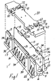
- Referring to the drawings, and initially to Figs. 1 to 5 thereof, there is illustrated a cable duct according to the invention indicated generally by the
reference numeral 1. Theduct 1 is formed from plastics material using a structural foam injection moulding process which incorporates injecting nitrogen gas into the melt at the moulding stage. This results in an aerated bubble/honeycomb structure in the wall section which combines light weight and high strength in the duct. - The
duct 1 has abase 2 withupstanding side walls 3 at opposite sides of thebase 2 forming with thebase 2 an open ended channel for reception of cables. Aduct interlocking device 5 is provided at each end of theduct 1 at thebase 2 for interlocking theduct 1 with anotherduct 1 end to end to form an extended channel for cables. - In this case, the interlocking
device 5 comprises acurved finger 6, eachfinger 6 for hooking engagement with acomplementary finger 6 on anotherduct 1 as shown in Fig. 2. Acurved slot 7 behind eachfinger 6 receives anotherfinger 6 for hooking engagement of thefingers 6 as shown in Fig. 2. To prevent relative vertical movement between a pair of interlockedducts 1, atongue 8 is associated with eachfinger 6. Thetongue 8 is spaced-apart from thefinger 6 within theslot 7 and vertically displaced below thefinger 6 so that when a pair offingers 6 interlock, atongue 8 associated with one of thefingers 6 engages beneath theother finger 6. This advantageously resists any vertical displacement of aduct 1 relative to an adjacent interlocked duct thus preventing a trip hazard. The interlockingdevice 5 allows semi-automatic and automatic installation ofducts 1. Further, the design of the interlockingdevice 5 is such that it allows 3° movement side to side. This advantageously facilitates gently curving a run ofducts 1 around a bend for example. - Each
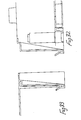
side wall 3 is of hollow construction comprising aninner wall 15 and anouter wall 16 spaced-apart from theinner wall 15. Internal ribs extend between the inner andouter walls side wall 3 is open at its lower end. Ashoulder 17 extends between an upper end of the inner andouter walls shoulder 17 is sloped outwardly and downwardly between theinner wall 15 and theouter wall 16 for water run-off.Upstanding flanges 19 form an extension of theinner walls 15 for positive location of acover 20 on theshoulders 17 to close theduct 1. - An outwardly extending
shoe 22 is provided at a lower end of eachside wall 3. Eachshoe 22 has anupper surface 23 which slopes upwardly and outwardly of theside wall 3 to facilitate keying theduct 1 into a foundation material, particularly where the foundation material is fine soil.External ribs 25 are also provided spaced-apart along eachouter wall 16 extending upwardly from theshoe 22 to assist in firmly bedding theduct 1 in a foundation material. - A pair of vertically disposed
housings 30 are provided spaced-apart on an outside of eachside wall 3. Eachhousing 30 forms a downwardly open socket for mounting theduct 1 onsupport posts 32 if desired as shown in Fig. 5. Aslot 34 is provided adjacent an upper end of eachhousing 30 for engagement by a clip, if desired, to hang theduct 1 in tunnels for example. It will be noted that eachhousing 30 projects above theouter wall 16 to provide with theflanges 19 for positive location of thecover 20 on theduct 1.Slots 36 are provided at an upper end of eachhousing 30 for engagement with hinge pins 37 on thecover 20 to allow hinging of thecover 20 on eitherside wall 3, if desired. - Referring now to Figs. 6 to 21 there is shown another
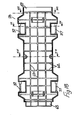
cable duct 40 which is largely similar to the cable duct previously described with reference to Figs. 1 to 5 and like parts are assigned the same reference numerals. - A number of knock-out panels 41 (Fig. 8) are provided in the
side walls 3 andbase 2 to allow cable entry and exit. - Referring to Fig. 8, a number of
upstanding ribs 42 are provided beneath thebase 2 extending between opposite sides of theduct 1 to provide strength and, as can be seen in Fig. 8, the underside of theduct 1 is of generally box section. Advantageously, the box section and ribbing allows the duct to bite into track-side ballast and soils. Further, the ribbing allows the mould for forming theduct 1 to readily and quickly fill during the moulding process. - Central slots 45 (Fig. 6) are provided in the
base 2 for reception of anupstanding divider panel 46 and to allow drainage. - Expansion means 50 is provided at each end of the duct to accommodate longitudinal expansion and contraction of the duct comprising a
curved flange 51 on one side and an associatedcurved housing 52 on the other side. As shown in Fig. 11 a pair ofducts 40 rotatably engage to interlock associatedflanges 51 andhousings 52 ofadjacent ducts 40. The expansion means 50 allows up to 6 mm longitudinal expansion of the duct to be absorbed. - Referring to Figs. 15 to 21, the
cover 20 is shown. Thecover 20 has a generally flat top 60 with aperipheral rim 61 which projects slightly above the top 60 and extends downwardly of the top 60.Ribs 62 extend downwardly from an inner surface of the top 60 within therim 61. Theseribs 62 ensure high strength and loading capability and ease the flow of material within the mould during the moulding process for forming thecover 20. The top 60 is provided with a number of upstanding spaced-apart projections 64 which provide an anti-slip surface. A plurality ofwater drainage slots 65 are provided in therim 61 to prevent water or frost build-up on the cover which would provide a slip hazard. The hinge pins 37 are mounted betweenprojections 67 at each side of thecover 20, each pair ofprojections 67 defining aslot 68 which locates with an upper end of thehousings 30 on theduct side walls 3. Expansion means for thecover 20 comprises an outwardly projectingtongue 63 at one end of thecover 20 and an associatedsocket 69 at the opposite end of thecover 20. On interlocked ducts thetongues 63 andsockets 69 ofadjacent covers 20 overlap to prevent ingress of dirt. - Referring to Fig. 22, either a
standard cover 20 or a lockingcover 70 may be provided for theducts cover 70 has aslot 71 extending through aneck portion 72 between theprojections 67 for reception of a lockingplate 74, outer ends of which engage complementary slots 75 at an upper end of thehousing 30 on theduct neck portion 72 to engage thelocking plates 74 to secure thecover 70 on theduct - Referring to Fig. 23, a T-junction 80 of similar construction to the
duct - Referring now to Figs. 24 to 33, there is illustrated another duct indicated generally by the
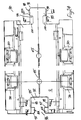
reference numeral 90. Thisduct 90 is largely similar to the ducts previously described, and like parts are assigned the same reference numerals. In this case, the interlocking means comprises amale connector 91 at one end of theduct 90 and a complementaryfemale receiver 92 at the opposite end of theduct 90. Themale connector 91 has abulbous head 93. A narrowedneck portion 94 connects thebulbous head 93 to thebase 2. Thefemale receiver 92 comprises a re-entrant slot having aninner portion 95 for reception of thebulbous head 93 and a narrowedmouth 96 defined bypillars 97 which engage behind thebulbous head 93 with theneck 94. Thus, a pair ofducts 90 can be interlocked by engaging thebulbous head 93 of oneduct 90 within the enlargedinner portion 95 of thefemale receiver 92. The width of thebulbous head 93 is somewhat smaller than the depth of theinner portion 93 and theneck 94 is somewhat deeper than thepillars 97 to allow for expansion and contraction of the ducts. - Complementary inter-engagable formations are provided on the
male connector 91 and thefemale receiver 92 to prevent relative vertical displacement of a pair ofinterconnected ducts 90. In this case, the formations comprise a pair of outwardly extendinglugs 98 on opposite sides of thebulbous head 93 at a bottom of thebulbous head 93. Theselugs 98 are engagable with associatedslots 99 provided at each side of theinner portion 95 of thefemale receiver 92. In addition,wings 100 are provided at an upper end of theneck 94 for engagement with associated steppedgrooves 101 at an upper end of eachpillar 97. - In use, a plurality of the
ducts ducts devices 5 preventing unauthorised dismantling of the channel formed by theducts - It will be appreciated that any suitable locking means may be provided for releasably locking the cover on the duct.
- The ducts may be also used for housing pipework or the like.
- The invention is not limited to the embodiments hereinbefore described which may be varied in both construction and detail.
Claims (17)
- A cable duct having a base with upstanding side walls at opposite sides of the base forming with the base an open ended channel for reception of cables, and means at each end of the duct for interlocking the duct with another duct end to end to form an extended channel for cables or the like.
- A cable duct as claimed in claim 1 wherein means is provided to prevent relative vertical movement between a pair of interlocked ducts.
- A cable duct as claimed in any preceding claim wherein expansion means is provided to facilitate longitudinal expansion of adjacent ducts when interlocked end to end.
- A cable duct as claimed in any preceding claim wherein the expansion means comprises complimentary inter-engagable formations at each end of the duct, the formations projecting outwardly of at least one end of the duct so that the associated formations on a pair of ducts overlap upon interlocking of said ducts to prevent ingress of material to the ducts, the cover for the duct also being provided with overlapping expansion formations at each end of the cover for overlapping engagement with adjacent covers.
- A cable duct as claimed in claim 3 or 4 wherein said expansion means comprises at each end of the duct a curved flange on one side wall and an associated curved housing on the other side wall, the flange of one duct being rotatably engagable with the housing on an adjacent duct when interlocking the ducts.
- A cable duct as claimed in any preceding claim wherein mounting means is provided on the duct for mounting the duct on one or more support posts.
- A cable duct as claimed in any preceding claim wherein an outwardly extending shoe is provided at a lower end of each side wall for keying the duct into a foundation material, an upper face of the shoe sloping upwardly and outwardly from the side wall.
- A cable duct as claimed in any preceding claim wherein the duct interlocking means is of two part construction comprising a male connector which is releasably engagable with a complementary female receiver, one of said parts being provided at each end of the duct.
- A cable duct as claimed in any preceding claim wherein the interlocking means comprises a curved finger at each end of the duct, each finger for hooking engagement with a complementary finger on another duct.
- A cable duct as claimed in claim 9 wherein the means to prevent relative vertical movement between a pair of interlocked ducts comprises a tongue associated with each finger, the tongue spaced-apart from the finger and vertically displaced relative to the finger so that when a pair of fingers interlock a tongue associated with one of the fingers engages beneath the other finger.
- A cable duct as claimed in claim 8 wherein the male part comprises a bulbous head connected to the base by a narrowed neck and the female receiver comprises a re-entrant slot in the base.
- A cable duct as claimed in any preceding claim wherein the base has a water drain channel in a top surface of the base.
- A cable duct as claimed in any preceding claim wherein a shoulder is formed at a top end of each side wall for reception of a cover engagable between the side walls to close the duct, the shoulder having an outwardly and downwardly sloping upper surface to facilitate water run-off.
- A cable duct as claimed in claim 13 wherein a hinge mount is formed at an upper end of one or both side walls for hingedly mounting the cover on the side walls.
- A cable duct as claimed in claim 13 or 14 wherein one or more water drainage slots are provided at an edge of a top surface of the cover.
- A cable duct as claimed in any of claims 13 to 15 wherein one or more hinge pins are provided at an edge of the cover for engagement with the hinge mount on the duct.
- A cable duct as claimed in any of claims 13 to 16 wherein locking means is provided for releasably securing the cover on the duct.
Applications Claiming Priority (2)
| Application Number | Priority Date | Filing Date | Title |
|---|---|---|---|
| IE950850 | 1995-11-03 | ||
| IE950850 | 1995-11-03 |
Publications (3)
| Publication Number | Publication Date |
|---|---|
| EP0772271A2 true EP0772271A2 (en) | 1997-05-07 |
| EP0772271A3 EP0772271A3 (en) | 1998-05-06 |
| EP0772271B1 EP0772271B1 (en) | 2005-10-26 |
Family
ID=11040952
Family Applications (1)
| Application Number | Title | Priority Date | Filing Date |
|---|---|---|---|
| EP96650049A Expired - Lifetime EP0772271B1 (en) | 1995-11-03 | 1996-11-04 | A cable duct |
Country Status (4)
| Country | Link |
|---|---|
| EP (1) | EP0772271B1 (en) |
| AT (1) | ATE308138T1 (en) |
| AU (1) | AU721837B2 (en) |
| DE (1) | DE69635335D1 (en) |
Cited By (4)
| Publication number | Priority date | Publication date | Assignee | Title |
|---|---|---|---|---|
| EP1102376A1 (en) * | 1999-11-19 | 2001-05-23 | Tehalit GmbH | Cable duct |
| WO2002027882A1 (en) * | 2000-09-26 | 2002-04-04 | Andrews Kent And Stone Pty Ltd | Ducting associated with rail track and installing apparatus |
| WO2006040567A1 (en) | 2004-10-15 | 2006-04-20 | Trojan Services Limited | Improvements in and relating to trunking |
| EP3940147A1 (en) * | 2020-07-15 | 2022-01-19 | Trojan Services Limited | A foundation unit |
Family Cites Families (5)
| Publication number | Priority date | Publication date | Assignee | Title |
|---|---|---|---|---|
| DE7015776U (en) * | 1970-04-27 | 1970-11-26 | Niedax Gmbh | REGISTER RAIL ELEMENT. |
| DE2124163C2 (en) * | 1971-05-14 | 1981-10-15 | Tehalit Kunststoffwerk Gmbh, 6751 Heltersberg | Flush mounted cable duct with rectangular cross=section - has cable duct covers hinged at one edge to duct side and intermediate walls |
| BE795365A (en) * | 1972-02-22 | 1973-05-29 | Gouda Holland N V | GUTTER-SHAPED BODY FOR CANALIZING ELECTRIC CABLES |
| DE8018534U1 (en) * | 1980-07-10 | 1981-01-15 | Licentia Patent-Verwaltungs-Gmbh, 6000 Frankfurt | Cable entry |
| DE8605355U1 (en) * | 1986-02-27 | 1991-02-28 | Thyssen Polymer Gmbh, 8000 Muenchen, De |
-
1996
- 1996-11-04 AT AT96650049T patent/ATE308138T1/en not_active IP Right Cessation
- 1996-11-04 AU AU70572/96A patent/AU721837B2/en not_active Expired
- 1996-11-04 EP EP96650049A patent/EP0772271B1/en not_active Expired - Lifetime
- 1996-11-04 DE DE69635335T patent/DE69635335D1/en not_active Expired - Fee Related
Non-Patent Citations (1)
| Title |
|---|
| None |
Cited By (6)
| Publication number | Priority date | Publication date | Assignee | Title |
|---|---|---|---|---|
| EP1102376A1 (en) * | 1999-11-19 | 2001-05-23 | Tehalit GmbH | Cable duct |
| WO2002027882A1 (en) * | 2000-09-26 | 2002-04-04 | Andrews Kent And Stone Pty Ltd | Ducting associated with rail track and installing apparatus |
| US6843181B2 (en) | 2000-09-26 | 2005-01-18 | Jonathan Mark Morris | Ducting associated with rail track and installing apparatus |
| CN100364196C (en) * | 2000-09-26 | 2008-01-23 | 乔纳森·马克·莫里斯 | Ducting associated with rail tract |
| WO2006040567A1 (en) | 2004-10-15 | 2006-04-20 | Trojan Services Limited | Improvements in and relating to trunking |
| EP3940147A1 (en) * | 2020-07-15 | 2022-01-19 | Trojan Services Limited | A foundation unit |
Also Published As
| Publication number | Publication date |
|---|---|
| AU721837B2 (en) | 2000-07-13 |
| DE69635335D1 (en) | 2005-12-01 |
| AU7057296A (en) | 1997-05-08 |
| EP0772271A3 (en) | 1998-05-06 |
| ATE308138T1 (en) | 2005-11-15 |
| EP0772271B1 (en) | 2005-10-26 |
Similar Documents
| Publication | Publication Date | Title |
|---|---|---|
| US4059362A (en) | Concrete highway traffic barricade having integrally formed coupling | |
| EP0206996B1 (en) | Sidewall extension for drainage channel system and method for extending the continuous slope of a drainage channel system | |
| EP1437447B1 (en) | Method and apparatus for aligning channel sections with an adjustable alignment key | |
| US4826351A (en) | Grid plate of plastic material | |
| US6484451B1 (en) | Stackable riser resistant to soil movement | |
| US4113400A (en) | Impact resistant tongue-and-groove coupling for highway traffic barricades | |
| JP2003510480A (en) | Trench cover element | |
| US11600980B2 (en) | Cable trough with an integrated walkway function for use in railways | |
| US6712546B1 (en) | Polymeric forms for moldable building material structures | |
| EP0772271B1 (en) | A cable duct | |
| US6203245B1 (en) | Culvert end guard | |
| EP1807918B1 (en) | Improvements in and relating to trunking | |
| GB2238815A (en) | Trench cover | |
| WO1994001907A1 (en) | Cable channelling | |
| WO1998047212A1 (en) | Improvements in and relating to cable ducts and walkways | |
| KR100872126B1 (en) | trough and the construction method of this for cable laying under the ground | |
| KR100929498B1 (en) | Cable troughs for bridges | |
| US20220344923A1 (en) | A combined cable trough and walkway | |
| US5179752A (en) | Cover for trenches | |
| KR20060118381A (en) | It is reinforcement re-union structure of plastic ash to a panel breast wall | |
| GB2257490A (en) | Ducting | |
| JP2000017720A (en) | Channel block | |
| CA2276867C (en) | Culvert end guard | |
| US20230344211A1 (en) | Cable housing container | |
| JP3639084B2 (en) | Retaining wall block having a coupling structure and method for constructing retaining wall using the retaining wall block |
Legal Events
| Date | Code | Title | Description |
|---|---|---|---|
| PUAI | Public reference made under article 153(3) epc to a published international application that has entered the european phase |
Free format text: ORIGINAL CODE: 0009012 |
|
| AK | Designated contracting states |
Kind code of ref document: A2 Designated state(s): AT BE CH DE DK ES FI FR GB GR IE IT LI LU MC NL PT SE |
|
| PUAL | Search report despatched |
Free format text: ORIGINAL CODE: 0009013 |
|
| AK | Designated contracting states |
Kind code of ref document: A3 Designated state(s): AT BE CH DE DK ES FI FR GB GR IE IT LI LU MC NL PT SE |
|
| 17P | Request for examination filed |
Effective date: 19981105 |
|
| 17Q | First examination report despatched |
Effective date: 20040315 |
|
| GRAP | Despatch of communication of intention to grant a patent |
Free format text: ORIGINAL CODE: EPIDOSNIGR1 |
|
| GRAS | Grant fee paid |
Free format text: ORIGINAL CODE: EPIDOSNIGR3 |
|
| GRAA | (expected) grant |
Free format text: ORIGINAL CODE: 0009210 |
|
| AK | Designated contracting states |
Kind code of ref document: B1 Designated state(s): AT BE CH DE DK ES FI FR GB GR IE IT LI LU MC NL PT SE |
|
| PG25 | Lapsed in a contracting state [announced via postgrant information from national office to epo] |
Ref country code: NL Free format text: LAPSE BECAUSE OF FAILURE TO SUBMIT A TRANSLATION OF THE DESCRIPTION OR TO PAY THE FEE WITHIN THE PRESCRIBED TIME-LIMIT Effective date: 20051026 Ref country code: LI Free format text: LAPSE BECAUSE OF FAILURE TO SUBMIT A TRANSLATION OF THE DESCRIPTION OR TO PAY THE FEE WITHIN THE PRESCRIBED TIME-LIMIT Effective date: 20051026 Ref country code: IT Free format text: LAPSE BECAUSE OF FAILURE TO SUBMIT A TRANSLATION OF THE DESCRIPTION OR TO PAY THE FEE WITHIN THE PRESCRIBED TIME-LIMIT;WARNING: LAPSES OF ITALIAN PATENTS WITH EFFECTIVE DATE BEFORE 2007 MAY HAVE OCCURRED AT ANY TIME BEFORE 2007. THE CORRECT EFFECTIVE DATE MAY BE DIFFERENT FROM THE ONE RECORDED. Effective date: 20051026 Ref country code: FI Free format text: LAPSE BECAUSE OF FAILURE TO SUBMIT A TRANSLATION OF THE DESCRIPTION OR TO PAY THE FEE WITHIN THE PRESCRIBED TIME-LIMIT Effective date: 20051026 Ref country code: CH Free format text: LAPSE BECAUSE OF FAILURE TO SUBMIT A TRANSLATION OF THE DESCRIPTION OR TO PAY THE FEE WITHIN THE PRESCRIBED TIME-LIMIT Effective date: 20051026 Ref country code: BE Free format text: LAPSE BECAUSE OF FAILURE TO SUBMIT A TRANSLATION OF THE DESCRIPTION OR TO PAY THE FEE WITHIN THE PRESCRIBED TIME-LIMIT Effective date: 20051026 Ref country code: AT Free format text: LAPSE BECAUSE OF FAILURE TO SUBMIT A TRANSLATION OF THE DESCRIPTION OR TO PAY THE FEE WITHIN THE PRESCRIBED TIME-LIMIT Effective date: 20051026 |
|
| REG | Reference to a national code |
Ref country code: GB Ref legal event code: FG4D |
|
| REG | Reference to a national code |
Ref country code: CH Ref legal event code: EP |
|
| PG25 | Lapsed in a contracting state [announced via postgrant information from national office to epo] |
Ref country code: MC Free format text: LAPSE BECAUSE OF NON-PAYMENT OF DUE FEES Effective date: 20051130 |
|
| REG | Reference to a national code |
Ref country code: IE Ref legal event code: FG4D |
|
| REF | Corresponds to: |
Ref document number: 69635335 Country of ref document: DE Date of ref document: 20051201 Kind code of ref document: P |
|
| PG25 | Lapsed in a contracting state [announced via postgrant information from national office to epo] |
Ref country code: LU Free format text: LAPSE BECAUSE OF NON-PAYMENT OF DUE FEES Effective date: 20051226 |
|
| PG25 | Lapsed in a contracting state [announced via postgrant information from national office to epo] |
Ref country code: SE Free format text: LAPSE BECAUSE OF FAILURE TO SUBMIT A TRANSLATION OF THE DESCRIPTION OR TO PAY THE FEE WITHIN THE PRESCRIBED TIME-LIMIT Effective date: 20060126 Ref country code: GR Free format text: LAPSE BECAUSE OF FAILURE TO SUBMIT A TRANSLATION OF THE DESCRIPTION OR TO PAY THE FEE WITHIN THE PRESCRIBED TIME-LIMIT Effective date: 20060126 Ref country code: DK Free format text: LAPSE BECAUSE OF FAILURE TO SUBMIT A TRANSLATION OF THE DESCRIPTION OR TO PAY THE FEE WITHIN THE PRESCRIBED TIME-LIMIT Effective date: 20060126 |
|
| PG25 | Lapsed in a contracting state [announced via postgrant information from national office to epo] |
Ref country code: ES Free format text: LAPSE BECAUSE OF FAILURE TO SUBMIT A TRANSLATION OF THE DESCRIPTION OR TO PAY THE FEE WITHIN THE PRESCRIBED TIME-LIMIT Effective date: 20060206 |
|
| PG25 | Lapsed in a contracting state [announced via postgrant information from national office to epo] |
Ref country code: PT Free format text: LAPSE BECAUSE OF FAILURE TO SUBMIT A TRANSLATION OF THE DESCRIPTION OR TO PAY THE FEE WITHIN THE PRESCRIBED TIME-LIMIT Effective date: 20060327 |
|
| NLV1 | Nl: lapsed or annulled due to failure to fulfill the requirements of art. 29p and 29m of the patents act | ||
| REG | Reference to a national code |
Ref country code: CH Ref legal event code: PL |
|
| PG25 | Lapsed in a contracting state [announced via postgrant information from national office to epo] |
Ref country code: DE Free format text: LAPSE BECAUSE OF NON-PAYMENT OF DUE FEES Effective date: 20060601 |
|
| PLBE | No opposition filed within time limit |
Free format text: ORIGINAL CODE: 0009261 |
|
| STAA | Information on the status of an ep patent application or granted ep patent |
Free format text: STATUS: NO OPPOSITION FILED WITHIN TIME LIMIT |
|
| 26N | No opposition filed |
Effective date: 20060727 |
|
| EN | Fr: translation not filed | ||
| PG25 | Lapsed in a contracting state [announced via postgrant information from national office to epo] |
Ref country code: FR Free format text: LAPSE BECAUSE OF FAILURE TO SUBMIT A TRANSLATION OF THE DESCRIPTION OR TO PAY THE FEE WITHIN THE PRESCRIBED TIME-LIMIT Effective date: 20061215 |
|
| PG25 | Lapsed in a contracting state [announced via postgrant information from national office to epo] |
Ref country code: FR Free format text: LAPSE BECAUSE OF FAILURE TO SUBMIT A TRANSLATION OF THE DESCRIPTION OR TO PAY THE FEE WITHIN THE PRESCRIBED TIME-LIMIT Effective date: 20051130 |
|
| PG25 | Lapsed in a contracting state [announced via postgrant information from national office to epo] |
Ref country code: FR Free format text: LAPSE BECAUSE OF FAILURE TO SUBMIT A TRANSLATION OF THE DESCRIPTION OR TO PAY THE FEE WITHIN THE PRESCRIBED TIME-LIMIT Effective date: 20051026 |
|
| REG | Reference to a national code |
Ref country code: GB Ref legal event code: 732E Free format text: REGISTERED BETWEEN 20101007 AND 20101013 |
|
| PGFP | Annual fee paid to national office [announced via postgrant information from national office to epo] |
Ref country code: IE Payment date: 20150908 Year of fee payment: 20 Ref country code: GB Payment date: 20150922 Year of fee payment: 20 |
|
| REG | Reference to a national code |
Ref country code: GB Ref legal event code: PE20 Expiry date: 20161103 |
|
| REG | Reference to a national code |
Ref country code: IE Ref legal event code: MK9A |
|
| PG25 | Lapsed in a contracting state [announced via postgrant information from national office to epo] |
Ref country code: IE Free format text: LAPSE BECAUSE OF EXPIRATION OF PROTECTION Effective date: 20161104 Ref country code: GB Free format text: LAPSE BECAUSE OF EXPIRATION OF PROTECTION Effective date: 20161103 |