EP0771932A1 - Rectifying stabiliser to drill an oil well - Google Patents
Rectifying stabiliser to drill an oil well Download PDFInfo
- Publication number
- EP0771932A1 EP0771932A1 EP96402304A EP96402304A EP0771932A1 EP 0771932 A1 EP0771932 A1 EP 0771932A1 EP 96402304 A EP96402304 A EP 96402304A EP 96402304 A EP96402304 A EP 96402304A EP 0771932 A1 EP0771932 A1 EP 0771932A1
- Authority
- EP
- European Patent Office
- Prior art keywords
- drilling
- stabilizer
- plates
- blades
- drill string
- Prior art date
- Legal status (The legal status is an assumption and is not a legal conclusion. Google has not performed a legal analysis and makes no representation as to the accuracy of the status listed.)
- Withdrawn
Links
- 239000003381 stabilizer Substances 0.000 title claims abstract description 35
- 239000003129 oil well Substances 0.000 title claims abstract description 7
- 238000005553 drilling Methods 0.000 claims abstract description 22
- 238000006243 chemical reaction Methods 0.000 claims abstract description 3
- 238000004140 cleaning Methods 0.000 claims abstract description 3
- 230000006641 stabilisation Effects 0.000 claims 1
- 238000011105 stabilization Methods 0.000 claims 1
- 238000006073 displacement reaction Methods 0.000 abstract 1
- 230000003019 stabilising effect Effects 0.000 abstract 1
- 208000031968 Cadaver Diseases 0.000 description 2
- 230000007246 mechanism Effects 0.000 description 2
- OANVFVBYPNXRLD-UHFFFAOYSA-M propyromazine bromide Chemical compound [Br-].C12=CC=CC=C2SC2=CC=CC=C2N1C(=O)C(C)[N+]1(C)CCCC1 OANVFVBYPNXRLD-UHFFFAOYSA-M 0.000 description 2
- 238000013517 stratification Methods 0.000 description 2
- 240000008042 Zea mays Species 0.000 description 1
- 230000009471 action Effects 0.000 description 1
- 230000004913 activation Effects 0.000 description 1
- 230000006978 adaptation Effects 0.000 description 1
- 230000000903 blocking effect Effects 0.000 description 1
- 239000004927 clay Substances 0.000 description 1
- 230000006866 deterioration Effects 0.000 description 1
- 229910003460 diamond Inorganic materials 0.000 description 1
- 239000010432 diamond Substances 0.000 description 1
- 239000004459 forage Substances 0.000 description 1
- 229930195733 hydrocarbon Natural products 0.000 description 1
- 150000002430 hydrocarbons Chemical class 0.000 description 1
- 230000007257 malfunction Effects 0.000 description 1
- 230000004048 modification Effects 0.000 description 1
- 238000012986 modification Methods 0.000 description 1
- 235000010603 pastilles Nutrition 0.000 description 1
- 230000009467 reduction Effects 0.000 description 1
- 239000011435 rock Substances 0.000 description 1
- 239000003351 stiffener Substances 0.000 description 1
Images


Classifications
-
- E—FIXED CONSTRUCTIONS
- E21—EARTH DRILLING; MINING
- E21B—EARTH DRILLING, e.g. DEEP DRILLING; OBTAINING OIL, GAS, WATER, SOLUBLE OR MELTABLE MATERIALS OR A SLURRY OF MINERALS FROM WELLS
- E21B10/00—Drill bits
- E21B10/26—Drill bits with leading portion, i.e. drill bits with a pilot cutter; Drill bits for enlarging the borehole, e.g. reamers
- E21B10/32—Drill bits with leading portion, i.e. drill bits with a pilot cutter; Drill bits for enlarging the borehole, e.g. reamers with expansible cutting tools
- E21B10/322—Drill bits with leading portion, i.e. drill bits with a pilot cutter; Drill bits for enlarging the borehole, e.g. reamers with expansible cutting tools cutter shifted by fluid pressure
-
- E—FIXED CONSTRUCTIONS
- E21—EARTH DRILLING; MINING
- E21B—EARTH DRILLING, e.g. DEEP DRILLING; OBTAINING OIL, GAS, WATER, SOLUBLE OR MELTABLE MATERIALS OR A SLURRY OF MINERALS FROM WELLS
- E21B10/00—Drill bits
- E21B10/003—Drill bits with cutting edges facing in opposite axial directions
Definitions
- the present invention relates to a reamer stabilizer for drilling oil wells.
- This mechanism causes a lateral shift causing a real stair step in the longitudinal profile of the well.
- This irregularity can block the passage of the tool if it occurred in front of the tool in a part already drilled during a descent of the rod train. If it occurs behind the tool or behind a stabilizer, it brakes and can even irreparably block the ascent of the drill string.
- the blockage manifests itself firstly by an increase in pulls, the torque, a loss of rotation, then a jamming upwards, then in case of excessive efforts a jamming downwards.
- the jamming generally manifests itself during the ascent of the drill string, by blocking the stabilizers which are at the nominal diameter of the hole.
- Incidents of this type encountered during drilling result in significant loss of time, a few weeks or months on certain drilling, which translate into additional capital costs for drilling barges of up to several million francs.
- the present invention therefore relates to a reamer stabilizer which allows to reinforce ground accidents in the well during the ascent of the drill string.
- the invention provides a stabilizer having a true cutter system which includes reinforced and retractable blades.
- FIG. 1 is a schematic sectional view of an oil well
- FIGS. 2A and 2B are the sections of a well with landslides
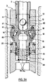
- Figures 3A and 3B present the details of the stabilizer and the bore system.
- Figure 1 shows the general section of an oil well (1) with the drill string (2), the stabilizers (3) which serve to center the rods between the walls of the well (4).
- the drill string ends with the drilling tool (5).
- FIG. 2A represents the section of a well with a sliding of the grounds (6) on a clay layer (7).
- FIG. 2B shows the same sliding phenomenon, with the stabilizer (3) jamming against a stair step (8) when raising the drill string.
- the stabilizer can only pass this obstacle if the stair tread is drilled up by the improved stabilizer object of the invention.
Abstract
Description
La présente invention se rapporte à un stabilisateur réaléseur pour le forage de puits pétroliers.The present invention relates to a reamer stabilizer for drilling oil wells.
Lors des forages de puits de pétrole, on rencontre souvent des massifs rocheux comportant des fractures, failles, ou même des joints de stratification (tels les séries argilo-gréseuses, les flysch) qui peuvent être le siège d'instabilités particulières par glissement sur ces fractures, failles ou joints de stratification.When drilling oil wells, we often encounter rock masses with fractures, faults, or even stratification joints (such as clay-sandstone series, flysch) which can be the seat of particular instabilities by sliding on these fractures, faults or stratification joints.
Ce mécanisme cause un décalage latéral provoquant une véritable marche d'escalier dans le profil longitudinal du puits. Cette irrégularité peut bloquer le passage de l'outil si elle est survenue en avant de l'outil dans une partie déjà forée lors d'une redescente du train de tige. Si elle survient derrière l'outil ou derrière un stabilisateur, elle freine et peut même bloquer irrémédiablement la remontée du train de tiges. Le blocage se manifeste d'abord par une augmentation des tractions, du couple, une perte de la rotation, ensuite un coincement vers le haut, puis en cas d'efforts excessifs un coincement vers le bas.This mechanism causes a lateral shift causing a real stair step in the longitudinal profile of the well. This irregularity can block the passage of the tool if it occurred in front of the tool in a part already drilled during a descent of the rod train. If it occurs behind the tool or behind a stabilizer, it brakes and can even irreparably block the ascent of the drill string. The blockage manifests itself firstly by an increase in pulls, the torque, a loss of rotation, then a jamming upwards, then in case of excessive efforts a jamming downwards.
Les moyens classiques de dégagement (tractions, coulisses) ne parviennent en général qu'à mieux engager la partie coincée dans le siège du coincement, pour en définitive aboutir à un coincement total, nécessitant dévissage, abandon de la partie coincée et départ en déviation.Conventional means of release (pulls, slides) generally only succeed in better engaging the jammed part in the jamming seat, in the end leading to total jamming, requiring unscrewing, abandoning the jammed part and departure in deflection.
Le coincement se manifeste généralement au cours de la remontée du train de tiges, en bloquant les stabilisateurs qui sont au diamètre nominal du trou.The jamming generally manifests itself during the ascent of the drill string, by blocking the stabilizers which are at the nominal diameter of the hole.
Les incidents de ce type rencontrés lors des forages entraînent des pertes de temps importantes, quelques semaines ou quelques mois sur certains forages, qui se traduisent par des coûts supplémentaires d'immobilisation des barges de forage pouvant atteindre plusieurs millions de francs.Incidents of this type encountered during drilling result in significant loss of time, a few weeks or months on certain drilling, which translate into additional capital costs for drilling barges of up to several million francs.
Des études ont été faites pour réaliser des stabilisateurs avec les épaulements arrières renforcés ou équipés de pastilles, mais cette modification est mal adaptée à un réalésage de profil de trou résultant du type d'instabilités décrites ci-dessus par le mécanisme de glissement, et les essais n'ont pas été concluants.Studies have been made to make stabilizers with the rear shoulders reinforced or fitted with pads, but this modification is ill-suited to a reaming of the hole profile resulting from the type of instabilities described above by the sliding mechanism, and the trials have not been successful.
La présente invention a donc pour objet un stabilisateur réaléseur qui permet de reforer les accidents de terrain dans le puits lors de la remontée du train de tiges.The present invention therefore relates to a reamer stabilizer which allows to reinforce ground accidents in the well during the ascent of the drill string.
Pour ce faire, l'invention propose un stabilisateur possédant un véritable système de fraise qui comprend des lames renforcées et rétractables.To do this, the invention provides a stabilizer having a true cutter system which includes reinforced and retractable blades.
Les caractéristiques et avantages de la présente invention apparaîtront plus clairement à la lecture de la description ci-après faite en référence aux dessins annexés sur lesquels la figure 1 est une vue schématique en coupe d'un puits de pétrole, les figures 2A et 2B sont les coupes d'un puits avec glissements de terrains et les figures 3A et 3B présentent les détails des stabilisateur et du système d'alésage.The characteristics and advantages of the present invention will appear more clearly on reading the description below made with reference to the accompanying drawings in which FIG. 1 is a schematic sectional view of an oil well, FIGS. 2A and 2B are the sections of a well with landslides and Figures 3A and 3B present the details of the stabilizer and the bore system.
La figure 1 présente la coupe générale d'un puits pétrolier (1) avec le train de tiges de forage (2), les stabilisateurs (3) qui servent à centrer les tiges entre les parois du puits (4). Le train de tiges se termine par l'outil de forage (5).Figure 1 shows the general section of an oil well (1) with the drill string (2), the stabilizers (3) which serve to center the rods between the walls of the well (4). The drill string ends with the drilling tool (5).
La figure 2A représente la coupe d'un puits avec un glissement des terrains (6) sur une couche argileuse (7). Lors de la redescente du train de tiges dans un trou déjà foré, l'outil rencontre une marche d'escalier (8) qui bloque l'outil et qui doit être reforée.FIG. 2A represents the section of a well with a sliding of the grounds (6) on a clay layer (7). When lowering the drill string into a hole already drilled, the tool encounters a stair step (8) which blocks the tool and which must be reshaped.
La figure 2B représente le même phénomène de glissement, avec coincement du stabilisateur (3) contre une marche d'escalier (8) lors de la remontée du train de tiges. Le stabilisateur ne peut passer cet obstacle que si la marche d'escalier est forée en remontant par le stabilisateur perfectionné objet de l'invention.FIG. 2B shows the same sliding phenomenon, with the stabilizer (3) jamming against a stair step (8) when raising the drill string. The stabilizer can only pass this obstacle if the stair tread is drilled up by the improved stabilizer object of the invention.
Ce stabilisateur comprend un système escamotable de réalésage (voir figures 3A et 3B) constitué de plusieurs éléments :
- un corps (11) aux dimensions externes similaires aux tiges utilisées ou aux corps de stabilisateurs,
- une chemise de commande (12) équipée de joints (13) haut et bas assurant l'étanchéité intérieur-extérieur lorsque l'outil est en position rétracté. De plus, la chemise de commande (12) est équipée d'un support de bille (18) faisant également office de contrefort (raidisseur). Des évents de circulation de boue (19) créent la perte de charge nécessaire et donc une force suffisante pour assurer la translation de cette chemise en butée basse lorsque la bille (20) est en place ; ces évents sont partiellement obturables par bouchons vissés, pour une adaptation au débit utilisé,
- des lames d'alésage à double sens (14) équipées de pastilles de diamant (24) pivotant sur des axes (15) et maintenues en position d'ouverture par les manetons (16) reprenant l'intégralité de la charge radiale sans réaction axiale sur la chemise de commande (12),
- des taquets (17) solidaires des lames empêchent l'ouverture des lames au-delà du diamètre nominal du trou à restaurer,
- un ressort de rappel (21) ramène automatiquement la chemise (12) en position haute lorsque le débit est réduit ou arrêté (outil fermé),
- des lumières (22) et des duses amovibles (23) au travers desquelles circule la boue pour assurer le nettoyage des lames.
- a body (11) with external dimensions similar to the rods used or to the stabilizer bodies,
- a control jacket (12) fitted with top and bottom seals (13) ensuring the interior-exterior seal when the tool is in the retracted position. In addition, the control jacket (12) is equipped with a ball support (18) which also acts as a buttress (stiffener). Mud circulation vents (19) create the necessary pressure drop and therefore a sufficient force to ensure the translation of this liner into low stop when the ball (20) is in place; these vents are partially closable by screw caps, to adapt to the flow used,
- two-way boring blades (14) fitted with diamond pads (24) pivoting on axes (15) and held in the open position by the crankpins (16) taking up the entire radial load without axial reaction on the control jacket (12),
- cleats (17) integral with the blades prevent the blades from opening beyond the nominal diameter of the hole to be restored,
- a return spring (21) automatically returns the jacket (12) to the high position when the flow rate is reduced or stopped (tool closed),
- lights (22) and removable nozzles (23) through which the mud circulates to ensure the cleaning of the blades.
En forage normal (figure 3B), la force de rappel du ressort (21) est telle que la chemise demeure en position haute indépendamment du débit utilisé, tout le débit (Q1+Q2) passant par l'outil de forage ; si du réalésage doit être effectué, vers le haut ou le bas, la bille est lancée ; la surpression engendrée par les pertes de charge dans les évents (19) descend la chemise d'activation (12) qui ouvre les lames et dévie une partie du débit (Q1) sur celles-ci à travers les lumières (22) et les duses (23) (figure 3A).In normal drilling (Figure 3B), the return force of the spring (21) is such that the jacket remains in position high regardless of the flow used, all the flow (Q1 + Q2) passing through the drilling tool; if re-boring is to be carried out, up or down, the ball is launched; the overpressure generated by the pressure drops in the vents (19) lowers the activation jacket (12) which opens the blades and deflects part of the flow (Q1) on them through the lights (22) and the nozzles (23) (Figure 3A).
La réduction du débit permet à la chemise de remonter sous l'action du ressort rétablissant l'étanchéité entre l'intérieur et l'extérieur de la garniture pour le contrôle d'une venue d'hydrocarbures, le cas échéant. Toute augmentation du débit réouvre les lames de coupe ; les lames ne s'ouvrant pas au-delà du diamètre nominal de forage, tout incident de fermeture sera sans conséquence majeure, à l'exception d'une détérioration rapide des éléments de coupe, problème que la rétraction cherche à éviter.The reduction in flow allows the liner to rise under the action of the spring restoring the seal between the inside and the outside of the gasket to control the arrival of hydrocarbons, if necessary. Any increase in flow reopens the cutting blades; since the blades do not open beyond the nominal borehole diameter, any closure incident will have no major consequence, with the exception of rapid deterioration of the cutting elements, a problem that the retraction seeks to avoid.
Les avantages principaux apportés par ce stabilisateur réaléseur sont au nombre de trois :
- l'alésage est possible vers le haut et vers le bas, en raison de la forme incurvée des lames (14) et de la conception du maneton (16) qui tient les lames en position écartée quel que soit le sens de déplacement du stabilisateur vers le haut ou vers le bas,
- les conséquences graves ne sont pas à craindre en cas de mauvais fonctionnement du stabilisateur, puisque le diamètre maximum des lames ouvertes n'excède pas le diamètre du trou ; le stabilisateur ne risque pas de coincement,
- les éléments de coupe restent en parfait état lorsque le besoin s'en fait sentir puisque ils ne sont pas utilisés en forage normal, mais seulement dans des cas exceptionnels.
- reaming is possible up and down, due to the curved shape of the blades (14) and the design of the crankpin (16) which holds the blades in the spread position regardless of the direction of travel of the stabilizer up or down,
- the serious consequences are not to be feared in the event of a malfunction of the stabilizer, since the maximum diameter of the open blades does not exceed the diameter of the hole; the stabilizer does not risk being trapped,
- the cutting elements remain in perfect condition when the need arises since they are not used in normal drilling, but only in exceptional cases.
Claims (7)
Applications Claiming Priority (2)
| Application Number | Priority Date | Filing Date | Title |
|---|---|---|---|
| FR9512838A FR2740508B1 (en) | 1995-10-31 | 1995-10-31 | REALIZER STABILIZER FOR DRILLING AN OIL WELL |
| FR9512838 | 1995-10-31 |
Publications (1)
| Publication Number | Publication Date |
|---|---|
| EP0771932A1 true EP0771932A1 (en) | 1997-05-07 |
Family
ID=9484088
Family Applications (1)
| Application Number | Title | Priority Date | Filing Date |
|---|---|---|---|
| EP96402304A Withdrawn EP0771932A1 (en) | 1995-10-31 | 1996-10-30 | Rectifying stabiliser to drill an oil well |
Country Status (5)
| Country | Link |
|---|---|
| US (1) | US5788000A (en) |
| EP (1) | EP0771932A1 (en) |
| CA (1) | CA2189269A1 (en) |
| FR (1) | FR2740508B1 (en) |
| NO (1) | NO964591L (en) |
Cited By (5)
| Publication number | Priority date | Publication date | Assignee | Title |
|---|---|---|---|---|
| WO1999028588A1 (en) * | 1997-12-02 | 1999-06-10 | I.D.A. Corporation | Method and apparatus for enhancing production from a wellbore hole |
| WO2008107694A1 (en) * | 2007-03-08 | 2008-09-12 | National Oilwell Varco, L.P. | Downhole tool |
| CN101509353B (en) * | 2009-03-17 | 2011-04-06 | 武汉武大巨成加固实业有限公司 | Piston type multilayer expanding bit |
| GB2458527B (en) * | 2008-03-25 | 2012-07-25 | Hunting Welltonic Ltd | High expansion anchoring and stabilisation device |
| CN104100206A (en) * | 2014-07-18 | 2014-10-15 | 成都保瑞特钻头有限公司 | Drill bit with stabilizer |
Families Citing this family (58)
| Publication number | Priority date | Publication date | Assignee | Title |
|---|---|---|---|---|
| US6170576B1 (en) | 1995-09-22 | 2001-01-09 | Weatherford/Lamb, Inc. | Mills for wellbore operations |
| US6920944B2 (en) * | 2000-06-27 | 2005-07-26 | Halliburton Energy Services, Inc. | Apparatus and method for drilling and reaming a borehole |
| US6189631B1 (en) * | 1998-11-12 | 2001-02-20 | Adel Sheshtawy | Drilling tool with extendable elements |
| US7451836B2 (en) * | 2001-08-08 | 2008-11-18 | Smith International, Inc. | Advanced expandable reaming tool |
| US6971459B2 (en) * | 2002-04-30 | 2005-12-06 | Raney Richard C | Stabilizing system and methods for a drill bit |
| US7036611B2 (en) * | 2002-07-30 | 2006-05-02 | Baker Hughes Incorporated | Expandable reamer apparatus for enlarging boreholes while drilling and methods of use |
| US6929076B2 (en) | 2002-10-04 | 2005-08-16 | Security Dbs Nv/Sa | Bore hole underreamer having extendible cutting arms |
| US6926099B2 (en) * | 2003-03-26 | 2005-08-09 | Varel International, L.P. | Drill out bi-center bit and method for using same |
| US7252152B2 (en) * | 2003-06-18 | 2007-08-07 | Weatherford/Lamb, Inc. | Methods and apparatus for actuating a downhole tool |
| EP1706575B1 (en) * | 2003-11-28 | 2008-03-12 | Shell Internationale Researchmaatschappij B.V. | Drill bit with protection member |
| US7658241B2 (en) * | 2004-04-21 | 2010-02-09 | Security Dbs Nv/Sa | Underreaming and stabilizing tool and method for its use |
| WO2005124094A1 (en) * | 2004-06-09 | 2005-12-29 | Halliburton Energy Services N.V. | Enlarging and stabilising tool for a borehole |
| WO2007103245A2 (en) * | 2006-03-02 | 2007-09-13 | Baker Hughes Incorporated | Automated steerable hole enlargement drilling device and methods |
| US8875810B2 (en) | 2006-03-02 | 2014-11-04 | Baker Hughes Incorporated | Hole enlargement drilling device and methods for using same |
| US8028767B2 (en) * | 2006-12-04 | 2011-10-04 | Baker Hughes, Incorporated | Expandable stabilizer with roller reamer elements |
| US8657039B2 (en) | 2006-12-04 | 2014-02-25 | Baker Hughes Incorporated | Restriction element trap for use with an actuation element of a downhole apparatus and method of use |
| RU2462577C2 (en) | 2006-12-04 | 2012-09-27 | Бейкер Хьюз Инкорпорейтед | Expanding reamer for holes reaming and method of hole reaming |
| US7900717B2 (en) * | 2006-12-04 | 2011-03-08 | Baker Hughes Incorporated | Expandable reamers for earth boring applications |
| US7882905B2 (en) * | 2008-03-28 | 2011-02-08 | Baker Hughes Incorporated | Stabilizer and reamer system having extensible blades and bearing pads and method of using same |
| WO2009135116A2 (en) * | 2008-05-01 | 2009-11-05 | Baker Hughes Incorporated | Stabilizer and reamer system having extensible blades and bearing pads and methods of using same |
| EP2408993A4 (en) * | 2009-03-03 | 2014-04-09 | Baker Hughes Inc | Chip deflector on a blade of a downhole reamer and methods therefor |
| US8469097B2 (en) * | 2009-05-14 | 2013-06-25 | Baker Hughes Incorporated | Subterranean tubular cutter with depth of cut feature |
| US8297381B2 (en) | 2009-07-13 | 2012-10-30 | Baker Hughes Incorporated | Stabilizer subs for use with expandable reamer apparatus, expandable reamer apparatus including stabilizer subs and related methods |
| GB2472848A (en) * | 2009-08-21 | 2011-02-23 | Paul Bernard Lee | Downhole reamer apparatus |
| WO2011041521A2 (en) * | 2009-09-30 | 2011-04-07 | Baker Hughes Incorporated | Earth-boring tools having expandable cutting structures and methods of using such earth-boring tools |
| US9175520B2 (en) * | 2009-09-30 | 2015-11-03 | Baker Hughes Incorporated | Remotely controlled apparatus for downhole applications, components for such apparatus, remote status indication devices for such apparatus, and related methods |
| WO2011041562A2 (en) * | 2009-09-30 | 2011-04-07 | Baker Hughes Incorporated | Remotely controlled apparatus for downhole applications and methods of operation |
| MY168798A (en) | 2010-05-21 | 2018-12-04 | Smith International | Hydraulic actuation of a downhole tool assembly |
| DE102010027544A1 (en) * | 2010-07-16 | 2012-01-19 | Minova International Ltd. | Method for producing the drilling devices, especially for the pipe screen technology and drilling device |
| SA111320627B1 (en) | 2010-07-21 | 2014-08-06 | Baker Hughes Inc | Wellbore Tool With Exchangable Blades |
| SA111320712B1 (en) * | 2010-08-26 | 2014-10-22 | Baker Hughes Inc | Remotely-controlled device and method for downhole actuation |
| US8939236B2 (en) | 2010-10-04 | 2015-01-27 | Baker Hughes Incorporated | Status indicators for use in earth-boring tools having expandable members and methods of making and using such status indicators and earth-boring tools |
| CN103261560A (en) | 2010-11-08 | 2013-08-21 | 贝克休斯公司 | Tools for use in subterranean boreholes having expandable members and related methods |
| US8844635B2 (en) | 2011-05-26 | 2014-09-30 | Baker Hughes Incorporated | Corrodible triggering elements for use with subterranean borehole tools having expandable members and related methods |
| US20130043048A1 (en) * | 2011-08-17 | 2013-02-21 | Joseph C. Joseph | Systems and Methods for Selective Electrical Isolation of Downhole Tools |
| US9267331B2 (en) | 2011-12-15 | 2016-02-23 | Baker Hughes Incorporated | Expandable reamers and methods of using expandable reamers |
| US8960333B2 (en) | 2011-12-15 | 2015-02-24 | Baker Hughes Incorporated | Selectively actuating expandable reamers and related methods |
| US9140073B2 (en) * | 2011-12-23 | 2015-09-22 | Saudi Arabian Oil Company | Drill bit for use in boring a wellbore and subterranean fracturing |
| US9388638B2 (en) | 2012-03-30 | 2016-07-12 | Baker Hughes Incorporated | Expandable reamers having sliding and rotating expandable blades, and related methods |
| US9493991B2 (en) | 2012-04-02 | 2016-11-15 | Baker Hughes Incorporated | Cutting structures, tools for use in subterranean boreholes including cutting structures and related methods |
| US9068407B2 (en) | 2012-05-03 | 2015-06-30 | Baker Hughes Incorporated | Drilling assemblies including expandable reamers and expandable stabilizers, and related methods |
| US9394746B2 (en) | 2012-05-16 | 2016-07-19 | Baker Hughes Incorporated | Utilization of expandable reamer blades in rigid earth-boring tool bodies |
| US9404331B2 (en) * | 2012-07-31 | 2016-08-02 | Smith International, Inc. | Extended duration section mill and methods of use |
| US9725977B2 (en) | 2012-10-04 | 2017-08-08 | Baker Hughes Incorporated | Retractable cutting and pulling tool with uphole milling capability |
| US9366101B2 (en) | 2012-10-04 | 2016-06-14 | Baker Hughes Incorporated | Cutting and pulling tool with double acting hydraulic piston |
| US9290998B2 (en) | 2013-02-25 | 2016-03-22 | Baker Hughes Incorporated | Actuation mechanisms for downhole assemblies and related downhole assemblies and methods |
| US9677344B2 (en) | 2013-03-01 | 2017-06-13 | Baker Hughes Incorporated | Components of drilling assemblies, drilling assemblies, and methods of stabilizing drilling assemblies in wellbores in subterranean formations |
| US9341027B2 (en) | 2013-03-04 | 2016-05-17 | Baker Hughes Incorporated | Expandable reamer assemblies, bottom-hole assemblies, and related methods |
| US9284816B2 (en) | 2013-03-04 | 2016-03-15 | Baker Hughes Incorporated | Actuation assemblies, hydraulically actuated tools for use in subterranean boreholes including actuation assemblies and related methods |
| US9739094B2 (en) | 2013-09-06 | 2017-08-22 | Baker Hughes Incorporated | Reamer blades exhibiting at least one of enhanced gage cutting element backrakes and exposures and reamers so equipped |
| US20160168950A1 (en) * | 2014-12-15 | 2016-06-16 | International Tubular Services Limited | Mill valve system |
| US10174560B2 (en) | 2015-08-14 | 2019-01-08 | Baker Hughes Incorporated | Modular earth-boring tools, modules for such tools and related methods |
| WO2017053151A1 (en) | 2015-09-15 | 2017-03-30 | Abrado, Inc. | Downhole tubular milling apparatus, especially suitable for deployment on coiled tubing |
| CN107366509A (en) * | 2017-06-23 | 2017-11-21 | 西安石油大学 | Self-powered based on gas underbalance well drilling can deflecting bit |
| CN108060896B (en) * | 2018-01-24 | 2023-05-23 | 西南石油大学 | Mechanical downhole tool for realizing vertical drilling by utilizing screw cam |
| CN108756753B (en) * | 2018-07-23 | 2023-07-18 | 长江大学 | Drilling reaming device capable of repeatedly stretching |
| CN111075367B (en) * | 2019-12-12 | 2021-06-04 | 大庆市宏博晟达石油机械设备有限公司 | Sucker rod centralizer for oil field exploitation |
| CN113846972B (en) * | 2021-10-26 | 2023-08-11 | 国能神东煤炭集团有限责任公司 | Reaming device and reaming method |
Citations (10)
| Publication number | Priority date | Publication date | Assignee | Title |
|---|---|---|---|---|
| DE192753C (en) * | ||||
| US2634957A (en) * | 1950-07-31 | 1953-04-14 | William E Coyle | Flare drill |
| US2679383A (en) * | 1950-10-23 | 1954-05-25 | Regan Forge & Eng Co | Wall scraper for deep wells |
| US3050122A (en) * | 1960-04-04 | 1962-08-21 | Gulf Research Development Co | Formation notching apparatus |
| DE1152979B (en) * | 1961-04-08 | 1963-08-22 | Archer William Kammerer | Device for reworking boreholes |
| US3441307A (en) * | 1967-07-25 | 1969-04-29 | Charlie F Farmer | Electromagnetic well service tool |
| FR2132633A1 (en) * | 1971-04-12 | 1972-11-24 | Baker Oil Tools Inc | |
| WO1991009202A1 (en) * | 1989-12-19 | 1991-06-27 | Diamant Boart Stratabit S.A. | Drilling tool for widening a bore well |
| WO1993019281A1 (en) * | 1992-03-25 | 1993-09-30 | Atlantic Richfield Company | Well conduit cutting and milling apparatus and method |
| EP0577545A1 (en) * | 1992-06-19 | 1994-01-05 | Broder Ag | Drill bit |
Family Cites Families (6)
| Publication number | Priority date | Publication date | Assignee | Title |
|---|---|---|---|---|
| US4842083A (en) * | 1986-01-22 | 1989-06-27 | Raney Richard C | Drill bit stabilizer |
| US4693328A (en) * | 1986-06-09 | 1987-09-15 | Smith International, Inc. | Expandable well drilling tool |
| US4848490A (en) * | 1986-07-03 | 1989-07-18 | Anderson Charles A | Downhole stabilizers |
| CA2032022A1 (en) * | 1990-12-12 | 1992-06-13 | Paul Lee | Down hole drilling tool control mechanism |
| US5265684A (en) * | 1991-11-27 | 1993-11-30 | Baroid Technology, Inc. | Downhole adjustable stabilizer and method |
| CA2059910C (en) * | 1992-01-23 | 2001-10-30 | Paul Lee | Adjustable drilling mechanism |
-
1995
- 1995-10-31 FR FR9512838A patent/FR2740508B1/en not_active Expired - Fee Related
-
1996
- 1996-10-30 CA CA002189269A patent/CA2189269A1/en not_active Abandoned
- 1996-10-30 US US08/738,453 patent/US5788000A/en not_active Expired - Fee Related
- 1996-10-30 NO NO964591A patent/NO964591L/en not_active Application Discontinuation
- 1996-10-30 EP EP96402304A patent/EP0771932A1/en not_active Withdrawn
Patent Citations (10)
| Publication number | Priority date | Publication date | Assignee | Title |
|---|---|---|---|---|
| DE192753C (en) * | ||||
| US2634957A (en) * | 1950-07-31 | 1953-04-14 | William E Coyle | Flare drill |
| US2679383A (en) * | 1950-10-23 | 1954-05-25 | Regan Forge & Eng Co | Wall scraper for deep wells |
| US3050122A (en) * | 1960-04-04 | 1962-08-21 | Gulf Research Development Co | Formation notching apparatus |
| DE1152979B (en) * | 1961-04-08 | 1963-08-22 | Archer William Kammerer | Device for reworking boreholes |
| US3441307A (en) * | 1967-07-25 | 1969-04-29 | Charlie F Farmer | Electromagnetic well service tool |
| FR2132633A1 (en) * | 1971-04-12 | 1972-11-24 | Baker Oil Tools Inc | |
| WO1991009202A1 (en) * | 1989-12-19 | 1991-06-27 | Diamant Boart Stratabit S.A. | Drilling tool for widening a bore well |
| WO1993019281A1 (en) * | 1992-03-25 | 1993-09-30 | Atlantic Richfield Company | Well conduit cutting and milling apparatus and method |
| EP0577545A1 (en) * | 1992-06-19 | 1994-01-05 | Broder Ag | Drill bit |
Cited By (6)
| Publication number | Priority date | Publication date | Assignee | Title |
|---|---|---|---|---|
| WO1999028588A1 (en) * | 1997-12-02 | 1999-06-10 | I.D.A. Corporation | Method and apparatus for enhancing production from a wellbore hole |
| US6070677A (en) * | 1997-12-02 | 2000-06-06 | I.D.A. Corporation | Method and apparatus for enhancing production from a wellbore hole |
| WO2008107694A1 (en) * | 2007-03-08 | 2008-09-12 | National Oilwell Varco, L.P. | Downhole tool |
| GB2458527B (en) * | 2008-03-25 | 2012-07-25 | Hunting Welltonic Ltd | High expansion anchoring and stabilisation device |
| CN101509353B (en) * | 2009-03-17 | 2011-04-06 | 武汉武大巨成加固实业有限公司 | Piston type multilayer expanding bit |
| CN104100206A (en) * | 2014-07-18 | 2014-10-15 | 成都保瑞特钻头有限公司 | Drill bit with stabilizer |
Also Published As
| Publication number | Publication date |
|---|---|
| NO964591L (en) | 1997-05-02 |
| NO964591D0 (en) | 1996-10-30 |
| US5788000A (en) | 1998-08-04 |
| FR2740508A1 (en) | 1997-04-30 |
| CA2189269A1 (en) | 1997-05-01 |
| FR2740508B1 (en) | 1997-11-21 |
Similar Documents
| Publication | Publication Date | Title |
|---|---|---|
| EP0771932A1 (en) | Rectifying stabiliser to drill an oil well | |
| US10487628B2 (en) | One trip drill and casing scrape method and apparatus | |
| EP1519003B1 (en) | Removable seal | |
| EP3070256B1 (en) | Fill up and circulation tool and mudsaver valve | |
| US6425449B1 (en) | Up-hole pump-in core barrel apparatus | |
| CN110799722B (en) | Mitigating drilling lost circulation | |
| US6070670A (en) | Movement control system for wellbore apparatus and method of controlling a wellbore tool | |
| US10145193B2 (en) | Axially separating drill bucket | |
| US4256192A (en) | Pressure core barrel | |
| US9255448B2 (en) | Reaming shoe for increased borehole clearance and method of use | |
| JPS5833358B2 (en) | Kitsukuoversouch | |
| GB2309470A (en) | Apparatus for circulating fluid in a borehole | |
| JPS6078093A (en) | Fluid pressure type inner barrel of core boring apparatus ofdrill string | |
| US20020092656A1 (en) | Wear bushing running and retrieval tools | |
| US6155360A (en) | Retractable drill bit system | |
| US4019592A (en) | By-pass tool | |
| EP0198406A1 (en) | An improved hydraulic inner barrel in a drill string coring tool | |
| US3087558A (en) | Ball director for rock bits | |
| WO1990001102A1 (en) | Drilling device and method for the study and exploitation of the underground | |
| BE1004330A3 (en) | Dual core drilling devie. | |
| US2755070A (en) | Hydraulically expansible rotary drill bits | |
| US3802521A (en) | Well circulation tool | |
| US2107420A (en) | Whip stock removing device | |
| US3045752A (en) | Milling apparatus for removing objects from well bores | |
| US20160245033A1 (en) | Tool and method of operation for removing debris and/or a lodged tool from a wellbore |
Legal Events
| Date | Code | Title | Description |
|---|---|---|---|
| PUAI | Public reference made under article 153(3) epc to a published international application that has entered the european phase |
Free format text: ORIGINAL CODE: 0009012 |
|
| 17P | Request for examination filed |
Effective date: 19961104 |
|
| AK | Designated contracting states |
Kind code of ref document: A1 Designated state(s): AT BE CH DE DK ES FR GB GR IE IT LI LU MC NL PT SE |
|
| 17Q | First examination report despatched |
Effective date: 20010719 |
|
| STAA | Information on the status of an ep patent application or granted ep patent |
Free format text: STATUS: THE APPLICATION HAS BEEN WITHDRAWN |
|
| 18W | Application withdrawn |
Withdrawal date: 20020214 |