EP0771893A1 - Apparatus for providing reciprocating rotary drive to the detaching rollers of a combing machine - Google Patents
Apparatus for providing reciprocating rotary drive to the detaching rollers of a combing machine Download PDFInfo
- Publication number
- EP0771893A1 EP0771893A1 EP95830465A EP95830465A EP0771893A1 EP 0771893 A1 EP0771893 A1 EP 0771893A1 EP 95830465 A EP95830465 A EP 95830465A EP 95830465 A EP95830465 A EP 95830465A EP 0771893 A1 EP0771893 A1 EP 0771893A1
- Authority
- EP
- European Patent Office
- Prior art keywords
- sensor
- detaching
- distributor
- hydraulic
- distributor valve
- Prior art date
- Legal status (The legal status is an assumption and is not a legal conclusion. Google has not performed a legal analysis and makes no representation as to the accuracy of the status listed.)
- Granted
Links
Images


Classifications
-
- D—TEXTILES; PAPER
- D01—NATURAL OR MAN-MADE THREADS OR FIBRES; SPINNING
- D01G—PRELIMINARY TREATMENT OF FIBRES, e.g. FOR SPINNING
- D01G19/00—Combing machines
- D01G19/06—Details
- D01G19/26—Driving arrangements
Definitions
- the present invention relates to apparatus for providing reciprocating rotary drive to the detaching rollers of a combing machine, of the type comprising at least one detaching roller with a fixed axis and hydraulic drive means actuated by pressurised fluid through at least one distributor valve and kinematically connected to the at least one detaching roller to rotate it in both senses about the said axis.
- the combing operation is carried out by a combing machine having a circular comb which rotates continuously, a straight comb, a movable gripper unit which substantially reciprocates, and detaching rollers.
- the detaching rollers In each combing cycle of the machine, the detaching rollers must first rotate backwards through a predetermined angle to enable a predetermined length of the fibres which have already been combed to be superposed on those still to be combed and must then rotate forwards through a greater angle to advance the fibres to be combed.
- the rotary drive for the detaching rollers is derived from the main transmission of the combing machine.
- a further problem of these transmissions lies in the difficulty of driving the detaching rollers so that their movements accord with the desired law of motion and of varying the drive appropriately in a simple manner so as to optimise the law governing the movements of the detaching rollers according to the type of fibre to be combed.
- US Patent 3277790 discloses combing machines in which the reciprocating rotary drive for the detaching rollers is provided by an hydraulic motor supplied with pressurised fluid through a mechanically-controlled distributor valve.
- the present invention is based on the technical problem of devising apparatus for providing reciprocating rotary drive to the detaching rollers of a combing machine which has structural and functional characteristics such as to overcome the problems mentioned with reference to prior-art combing machines.
- apparatus for providing reciprocating rotary drive to the detaching rollers of a combing machine of the type specified which is characterised in that the at least one distributor valve is electrically controlled and in that it includes a first sensor which generates a signal correlated with the progress of the combing machine operating cycle, a second sensor which generates a signal correlated with the angular position of the at least one detaching roller and an electronic control and command unit connected to the first and second sensors for controlling the operation of the distributor valve in dependence on the signals generated by the first and second sensors.
- apparatus for providing reciprocating rotary drive to the detaching rollers of a combing machine is generally indicated 1.
- the combing machine includes a continuously-rotating circular comb, a straight comb and a movable gripper unit which substantially reciprocates, which, being of known type, are not shown in the drawings and are not described in detail below in order not to burden the present description.
- the combing machine includes two parallel detaching rollers 3 with axes A-A, located adjacent each other at a predetermined spacing D, each of which has an associated pressure roller 4 located parallel to and above it, in pressing contact therewith.
- the combing machine can thus be seen to include two pairs 2 of parallel rollers each of which is constituted by a detaching roller 3 and a respective pressure roller 4 the peripheral surfaces of which are in pressing contact so that they are coupled together for rotation.
- the detaching rollers 3 and the pressure rollers 4 are rotatably supported at their ends by a frame 5 of the combing machine ( Figure 2).
- the detaching rollers 3 of each pair 2 are kinematically connected together by a toothed transmission so that they are coupled together for rotation in the same sense.
- the transmission is achieved by the keying of a gear 6 to each end of the detaching rollers 3 and the connection of the gears 6 of one detaching roller 3 to the corresponding gears 6 of the other detaching roller 3 by respective identical idle gears 7 and 8 supported for rotation by the frame 5 of the combing machine.
- the apparatus 1 includes an hydraulic motor 9 of known type, the rotary drive shaft 10 of which is connected for rotation to the hub of the idle gear 7.
- the hydraulic motor 9 is driven through an hydraulic distributor 11 by pressurised fluid from an hydraulic circuit 12 including a fluid reservoir 13, a motor pump unit 14 mounted on a duct P which puts the reservoir 13 in fluid communication with an inlet I of the hydraulic distributor 11 and a duct T connecting an outlet O of the hydraulic distributor 11 to the reservoir 13.
- the hydraulic circuit 12 further includes elements such as filters, pressure switches, surge chambers, non-return valves etc. which, being of known type, are not shown in the drawings and are not described in detail below in order not to burden the present description but which however are included as far as necessary for the proper operation of the equipment.
- the hydraulic distributor 11 is of the proportional type with an electromagnetically controlled distributor slide 15 biased into a central closed position ( Figure 3) by a centring spring. Besides the inlet I and the outlet O the hydraulic distributor 11 also have two connections A and B in fluid communication with the hydraulic motor 9. The movement of the distributor slide 15 enables the inlet I and the outlet O of the hydraulic distributor 11 to be put into fluid communication with the connections A and B respectively or vice versa.
- the operation of the hydraulic distributor 11 is controlled by an electronic control unit 31 including an electronic amplifier 16 and an electronic data-processing unit 19.
- the electronic amplifier 16 is connected through an electrical conductor L1 to electromagnets 17 which drive the movements of the distributor slide 15.
- the electronic amplifier 16 is connected through a conductor S1 to a position detector 18, for example of the LVDT (linear variable differential transformer) type, associated with the distributor slide 15 and which can supply the electronic amplifier 16 with a signal related to the position of the distributor slide 15.
- a position detector 18 for example of the LVDT (linear variable differential transformer) type
- the electronic data-processing unit 19 is interfaced with the electronic amplifier 16 and is connected through an electrical conductor S2 to a sensor 20, for example an encoder, associated with the idle gear 8.
- the sensor 20 supplies the electronic data-processing unit 9 with a signal related to the angular position of the idle gear 8 and hence of the detaching rollers 3.
- the electronic data-processing unit 19 is connected by an electrical conductor S3 to a sensor 32 which is associated with the circular comb and supplies the electronic data-processing unit 19 with an electrical signal related to the angular position of the circular comb. Since the operating cycle of the combing machine is repeated on each complete rotation of the circular comb, this electrical signal is thus correlated with the progress of the machine operating cycle.
- the electronic data-processing unit 19 includes a microprocessor 21 (CPU) which is interfaced with a video-keyboard unit 22, with RAM and EPROM memories 23, with an analog/digital signal converter 24 and with a data input/output card 25 respectively.
- CPU microprocessor
- the data input/output card 25 is connected through the conductors S2 and S3 to the sensor 20 associated with the idle gear 8 and with the sensor 32 associated with a circular comb respectively, while it supplies the electronic amplifier 16 with an enabling signal through a conductor S4.
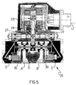
- the hydraulic distributor 11 may be replaced by an electrically-controlled, hydraulically-driven servovalve 26 for example of known two-stage type with nozzles 27 and a flapper plate 28 ( Figure 5).
- the first stage of the servovalve 26 comprises a torque motor 29 which is connected to the electronic amplifier 16 through the conductor L1 and drives the movement of the flapper plate 28 between the nozzles 27.
- the second stage comprises a distributor slide 30 which enables an inlet I and an outlet O to be connected to respective connections A and B connected to the hydraulic motor 9 and vice versa.
- the fluid of the hydraulic circuit 12 acts on opposite end faces of the distributor slide 30 with an equal pressure only when the flapper plate 28 is equidistant from the nozzles 27. Consequently, when the torque motor 29 moves the flapper plate 28 towards one of the nozzles 27, the pressure difference which is set up between the ends of the distributor slide 30 causes the slide itself to move.
- the servovalve 2 has an advantage over the hydraulic distributor 11 in that it moves the distributor slide 30 by means of the power supplied by the hydraulic circuit 12 on which the regulation is effected since the torque motor 29, through the conductor L1, takes only the power needed to position the flapper plate 28 between the nozzles 27.
- the fibres to be combed pass through the gripper unit, are combed by the circular comb and by the straight comb and pass between the detaching roller 3 and pressure roller 4 of each pair 2, from which the fibres are drawn.
- the detaching rollers 3 At each rotation of the circular comb, the detaching rollers 3, as already stated in the introduction to the present description, rotate in the sense opposing the advance of the fibres and then rotate in the opposite sense through a greater angle.
- the reciprocating rotation of the detaching rollers 3 through different angles is effected by the connection of the connections A and B of the hydraulic distributor 11 alternately in fluid communication with the ducts P and T of the hydraulic circuit 12 by suitable movement of the distributor slide 15 so as to rotate the hydraulic motor 9 since a predetermined rotation of the drive shaft 10 of the hydraulic motor 9 corresponds to a rotation of the detaching rollers 3 through an angle which depends on the transmission ratio between the idle gears 7 and 8 and the gears 6.
- the movement of the distributor slide 15 is controlled by the electronic data-processing unit 19 which supplies the electronic amplifier 16 with an electrical control signal which depends on the signals received from the sensor 20 associated with the idle gear 8 and the sensor 32 associated with the circular comb.
- the control signal after being processed appropriately by the electronic amplifier 16 in dependence on the signal supplied by the position detector 18 to the electronic amplifier 16, is fed to the electromagnets 17 of the hydraulic distributor 11 or, in the case of the servovalve 26, to the torque motor 29, so as to drive the required movement of the distributor slide 15.
- the apparatus according to the present invention enables the movements of the distributor slide to be governed accurately and appropriately by the electronic control and command unit 31, which enables the flow of pressurised fluid to the hydraulic motor 9 to be regulated precisely so as to rotate the detaching rollers 3 through different angles in opposite senses as required for the correct operation of the combing machine.
- respective devices according to the present invention for providing reciprocating rotary drive to the detaching rollers of a combing machine are generally indicated 601 and 701, these parts which are structurally and functionally equivalent to corresponding parts of the apparatus 1 being indicated by the same reference numerals and not being described below so as not to burden the present description to no purpose.
- the hydraulic drive means are constituted by two double acting hydraulic actuators 602 each having a piston head 603 defining two variable-volume chambers 604 and 605 within the actuator cylinder and a rod 606 fixed to the piston head 603.
- each piston 603 is kinematically connected to a detaching roller 3 by a known rack and pinion transmission and a unidirectional clutch device which enables the reciprocating rectilinear movement of the piston 603 to be converted into discontinuous rotary drive for the detaching roller 3.
- this transmission comprises, for each of the two hydraulic actuators 602, a rack 607 fixed for translational movement with the piston 603 and a pinion 608 meshed with the teeth of the rack 607 and keyed to a detaching roller 3 through a unidirectional clutch device 609, also known as a free wheel, which can transmit drive torque to the detaching roller 3 in only one rotational sense.
- one of the two unidirectional clutch devices 609 transmits torque and rotational drive to the detaching roller 3 in the opposite sense from those transmitted by the other unidirectional clutch device 609, as will become clearer in the description below.
- the apparatus 601 includes an hydraulic distributor 610 similar to the distributor 11 described above, having its inlet I and its outlet O respectively in fluid communication with the ducts P and T of the hydraulic circuit 12 and the connections A and B respectively in fluid communication with the variable-volume chambers 604 and 605 of the hydraulic actuator 602.
- the racks 607 are arranged, relative to the pistons 603 to which they are connected so that they supply pressurised fluid to one of the two variable-volume chambers 604 while simultaneously connecting the other to exhaust, or vice versa, so as to move the piston 603 of each hydraulic actuator 602 to rotate the pinions 608 in the same sense.
- the apparatus 601 further includes a manually-operable hydraulic distributor 611 having an inlet I connected to the pressurised fluid duct P, an outlet O connected to the duct T of the hydraulic circuit 12 and two connections A and B connected respectively in fluid communication with the connections A and B of the two hydraulic distributors 610.
- the hydraulic distributor 611 enables the pistons 603 of the two hydraulic actuators 602 to be put in phase with each other.
- the two hydraulic distributors 610 are controlled by the electronic amplifier 16 independently of each other in dependence on the electrical signal transmitted to the latter by the electronic data processing unit 19.
- the length of travel of the piston 603 of one of the two hydraulic actuators 602 determines the amplitude of the rotation of the detaching rollers 3 in one sense while the amplitude of the rotation of the detaching rollers 3 in the other sense is determined by the travel of the piston 603 of the other of the two hydraulic actuators 602.
- the hydraulic drive means are constituted by a double-acting hydraulic actuator 702 which includes a piston 703 defining two variable-volume chambers 704 in the hydraulic actuator 702 and a rod 705 connected to the piston 703.
- the rod 705 is fixed for translational movement with a rack 706 meshed with a pinion 707 kinematically connected to the hub of the idle gear 7 through a braked clutch unit 708 of known type.
- the braked clutch unit 708 comprises a friction disc fixed to an input shaft 709 to which the pinion 707 is keyed, a braked clutch disc fixed to an output shaft 710 to which the idle gear 7 is keyed, actuators, for example of electro-pneumatic type, for moving the clutch disc into engagement with the friction disc and friction means for braking the clutch disc when it is disengaged from the friction disc.
- An electronic control system 711 is connected to the braked clutch unit 708 by a conductor L3 and is connected to the electronic control and command unit 31 and, more precisely, to the electronic data processing unit 19, by an electrical conductor L4. Depending on the signal received from the electronic data processing unit 19, the electronic control system 711 causes the braked clutch disc to engage with the friction disc so as to connect the output shaft 710 rigidly for rotation with the input shaft 709.
- the apparatus 701 includes an hydraulic distributor 712 which is the same as the distributor 11 described previously having an input I and an outlet O respectively in fluid communication with the ducts P and T of the hydraulic circuit 12 and the connections A and B respectively in fluid communication with the variable-volume chambers 704 of the hydraulic actuator 702.
- the hydraulic distributor 712 is controlled by the electronic amplifier 16 in dependence on the electrical signal transmitted to the latter by the electronic data processing unit 19.
- the reciprocating rotation of the detaching rollers is achieved by the alternate supply of pressurised fluid from the hydraulic circuit 12 into one of the two variable volume chambers 704 of the hydraulic actuator 702 and the simultaneous connection of the other variable-volume chamber 704 to exhaust.
- the electronic control system 711 By controlling the engagement and disengagement of the braked clutch disc and the friction disc through the electronic control system 711, it is thus possible to rotate the detaching rollers 3 in the two senses through different angles.
- the law of motion which governs the rotation of the detaching rollers 3 can be varied by varying the parameters set in the memory of the electronic data processing unit 19.
- the apparatus for providing reciprocating rotary drive to the detaching rollers of a combing machine of the present invention enables the requirements referred to in the introduction to the present description to be satisfied while overcoming the problems of prior-art combing machines at the same time.
- a further advantage of the apparatus according to the present invention lies in the fact that it enables the law of motion which governs the rotation of the detaching rollers to be varied in a simple manner so as to optimise the operation of the machine to suit the type of fibres being combed.
- Another advantage of the apparatus according to the present invention lies in the fact that it is structurally and functionally simple so as to improve the reliability of the combing machine compared with that of prior-art machines.
- the combing machine may include a larger number of detaching rollers and the sensor associated with the circular comb may be replaced by a sensor associated with part of the combing machine which moves cyclically during each working cycle of the machine.
Landscapes
- Engineering & Computer Science (AREA)
- Textile Engineering (AREA)
- Preliminary Treatment Of Fibers (AREA)
Abstract
Description
- The present invention relates to apparatus for providing reciprocating rotary drive to the detaching rollers of a combing machine, of the type comprising at least one detaching roller with a fixed axis and hydraulic drive means actuated by pressurised fluid through at least one distributor valve and kinematically connected to the at least one detaching roller to rotate it in both senses about the said axis.
- It is known that, in the spinning of cotton, linen and long fibres in general, the combing operation is carried out by a combing machine having a circular comb which rotates continuously, a straight comb, a movable gripper unit which substantially reciprocates, and detaching rollers. In each combing cycle of the machine, the detaching rollers must first rotate backwards through a predetermined angle to enable a predetermined length of the fibres which have already been combed to be superposed on those still to be combed and must then rotate forwards through a greater angle to advance the fibres to be combed.
- It is equally well known that, in the combing operation, it is of fundamental importance not only that the detaching rollers should be rotated through a given angle in one sense and through a different angle in the opposite sense but also that the rotations should take place with suitable laws of motion. More particularly, in order to avoid the combs carrying away the long fibres during the combing operation, it is necessary for the forward rotation of the detaching rollers to occur with a high initial acceleration and with a subsequent phase at constant velocity while it is best that the reverse rotation of these rollers should be rapid.
- In combing machines in current use, the rotary drive for the detaching rollers is derived from the main transmission of the combing machine.
- However, the provision of derived rotary drive for the detaching rollers has the disadvantage of requiring the provision of very expensive and complicated mechanical transmissions. Moreover because of the high operating rate of the combing machine, the constituent parts of the transmissions are subject to high accelerations and thus to high dynamic stresses.
- A further problem of these transmissions lies in the difficulty of driving the detaching rollers so that their movements accord with the desired law of motion and of varying the drive appropriately in a simple manner so as to optimise the law governing the movements of the detaching rollers according to the type of fibre to be combed.
- US Patent 3277790 discloses combing machines in which the reciprocating rotary drive for the detaching rollers is provided by an hydraulic motor supplied with pressurised fluid through a mechanically-controlled distributor valve.
- In order to drive the slide of the distributor valve, however, these machines require a very complicated cam system which has the disadvantages of being difficult to design, difficult to calibrate and not very satisfactory from the point of view of long-term reliability and precision in use following the inevitable wear of the parts.
- Other combing machines have been proposed in which the reciprocating rotary drive for the detaching rollers is provided by one or more electric motors coupled to the detaching rollers by reduction systems.
- This solution is not very satisfactory, however, since the electric motors intended for this use must operate intermittently and thus under conditions far from their optimum operating conditions so that, to obtain the power needed to drive the detaching rollers without causing excessive heating of the electric motors, it is necessary to use over-dimensioned electric motors. The inertia of the rotors of these motors also impedes the movement of the detaching rollers in accordance with the desired law of motion.
- The present invention is based on the technical problem of devising apparatus for providing reciprocating rotary drive to the detaching rollers of a combing machine which has structural and functional characteristics such as to overcome the problems mentioned with reference to prior-art combing machines.
- This problem is solved by apparatus for providing reciprocating rotary drive to the detaching rollers of a combing machine of the type specified, which is characterised in that the at least one distributor valve is electrically controlled and in that it includes a first sensor which generates a signal correlated with the progress of the combing machine operating cycle, a second sensor which generates a signal correlated with the angular position of the at least one detaching roller and an electronic control and command unit connected to the first and second sensors for controlling the operation of the distributor valve in dependence on the signals generated by the first and second sensors.
- Further characteristics and advantages of the apparatus according to the present invention will become apparent from the description of several embodiments given below, purely by way of non-limitative example, with reference to the appended drawings, in which:
- Figure 1 is a schematic view of apparatus according to the present invention,
- Figures 2, 3 and 4 are views of a detail of the apparatus of Figure 1,
- Figure 5 shows a different embodiment of a detail of the apparatus of Figure 1, and
- Figures 6 and 7 show different embodiments of the apparatus according to the present invention.
- With reference to Figures 1 to 4, apparatus for providing reciprocating rotary drive to the detaching rollers of a combing machine is generally indicated 1.
- The combing machine includes a continuously-rotating circular comb, a straight comb and a movable gripper unit which substantially reciprocates, which, being of known type, are not shown in the drawings and are not described in detail below in order not to burden the present description.
- The combing machine includes two parallel detaching
rollers 3 with axes A-A, located adjacent each other at a predetermined spacing D, each of which has an associatedpressure roller 4 located parallel to and above it, in pressing contact therewith. The combing machine can thus be seen to include twopairs 2 of parallel rollers each of which is constituted by a detachingroller 3 and arespective pressure roller 4 the peripheral surfaces of which are in pressing contact so that they are coupled together for rotation. The detachingrollers 3 and thepressure rollers 4 are rotatably supported at their ends by aframe 5 of the combing machine (Figure 2). - The detaching
rollers 3 of eachpair 2 are kinematically connected together by a toothed transmission so that they are coupled together for rotation in the same sense. In the embodiment shown, the transmission is achieved by the keying of agear 6 to each end of the detachingrollers 3 and the connection of thegears 6 of one detachingroller 3 to thecorresponding gears 6 of the other detachingroller 3 by respectiveidentical idle gears 7 and 8 supported for rotation by theframe 5 of the combing machine. - The apparatus 1 includes an
hydraulic motor 9 of known type, therotary drive shaft 10 of which is connected for rotation to the hub of theidle gear 7. Thehydraulic motor 9 is driven through anhydraulic distributor 11 by pressurised fluid from anhydraulic circuit 12 including afluid reservoir 13, amotor pump unit 14 mounted on a duct P which puts thereservoir 13 in fluid communication with an inlet I of thehydraulic distributor 11 and a duct T connecting an outlet O of thehydraulic distributor 11 to thereservoir 13. Thehydraulic circuit 12 further includes elements such as filters, pressure switches, surge chambers, non-return valves etc. which, being of known type, are not shown in the drawings and are not described in detail below in order not to burden the present description but which however are included as far as necessary for the proper operation of the equipment. - The
hydraulic distributor 11 is of the proportional type with an electromagnetically controlled distributor slide 15 biased into a central closed position (Figure 3) by a centring spring. Besides the inlet I and the outlet O thehydraulic distributor 11 also have two connections A and B in fluid communication with thehydraulic motor 9. The movement of thedistributor slide 15 enables the inlet I and the outlet O of thehydraulic distributor 11 to be put into fluid communication with the connections A and B respectively or vice versa. - The operation of the
hydraulic distributor 11 is controlled by anelectronic control unit 31 including anelectronic amplifier 16 and an electronic data-processing unit 19. - The
electronic amplifier 16 is connected through an electrical conductor L1 toelectromagnets 17 which drive the movements of thedistributor slide 15. In addition, theelectronic amplifier 16 is connected through a conductor S1 to aposition detector 18, for example of the LVDT (linear variable differential transformer) type, associated with thedistributor slide 15 and which can supply theelectronic amplifier 16 with a signal related to the position of thedistributor slide 15. - The electronic data-
processing unit 19 is interfaced with theelectronic amplifier 16 and is connected through an electrical conductor S2 to asensor 20, for example an encoder, associated with the idle gear 8. Thesensor 20 supplies the electronic data-processing unit 9 with a signal related to the angular position of the idle gear 8 and hence of the detachingrollers 3. - The electronic data-
processing unit 19 is connected by an electrical conductor S3 to asensor 32 which is associated with the circular comb and supplies the electronic data-processing unit 19 with an electrical signal related to the angular position of the circular comb. Since the operating cycle of the combing machine is repeated on each complete rotation of the circular comb, this electrical signal is thus correlated with the progress of the machine operating cycle. - In a preferred embodiment, the electronic data-
processing unit 19 includes a microprocessor 21 (CPU) which is interfaced with a video-keyboard unit 22, with RAM andEPROM memories 23, with an analog/digital signal converter 24 and with a data input/output card 25 respectively. - The analog/
digital signal converter 24, through a conductor L2, supplies theelectronic amplifier 16 with a signal to be amplified for controlling the movement of thedistributor slide 15. - The data input/
output card 25 is connected through the conductors S2 and S3 to thesensor 20 associated with the idle gear 8 and with thesensor 32 associated with a circular comb respectively, while it supplies theelectronic amplifier 16 with an enabling signal through a conductor S4. - The
hydraulic distributor 11 may be replaced by an electrically-controlled, hydraulically-drivenservovalve 26 for example of known two-stage type withnozzles 27 and a flapper plate 28 (Figure 5). The first stage of theservovalve 26 comprises atorque motor 29 which is connected to theelectronic amplifier 16 through the conductor L1 and drives the movement of theflapper plate 28 between thenozzles 27. The second stage comprises adistributor slide 30 which enables an inlet I and an outlet O to be connected to respective connections A and B connected to thehydraulic motor 9 and vice versa. The fluid of thehydraulic circuit 12 acts on opposite end faces of the distributor slide 30 with an equal pressure only when theflapper plate 28 is equidistant from thenozzles 27. Consequently, when thetorque motor 29 moves theflapper plate 28 towards one of thenozzles 27, the pressure difference which is set up between the ends of thedistributor slide 30 causes the slide itself to move. - The
servovalve 2 has an advantage over thehydraulic distributor 11 in that it moves thedistributor slide 30 by means of the power supplied by thehydraulic circuit 12 on which the regulation is effected since thetorque motor 29, through the conductor L1, takes only the power needed to position theflapper plate 28 between thenozzles 27. - In operation of the apparatus 1, the fibres to be combed pass through the gripper unit, are combed by the circular comb and by the straight comb and pass between the detaching
roller 3 andpressure roller 4 of eachpair 2, from which the fibres are drawn. - At each rotation of the circular comb, the detaching
rollers 3, as already stated in the introduction to the present description, rotate in the sense opposing the advance of the fibres and then rotate in the opposite sense through a greater angle. - The reciprocating rotation of the detaching
rollers 3 through different angles is effected by the connection of the connections A and B of thehydraulic distributor 11 alternately in fluid communication with the ducts P and T of thehydraulic circuit 12 by suitable movement of thedistributor slide 15 so as to rotate thehydraulic motor 9 since a predetermined rotation of thedrive shaft 10 of thehydraulic motor 9 corresponds to a rotation of the detachingrollers 3 through an angle which depends on the transmission ratio between theidle gears 7 and 8 and thegears 6. - The movement of the
distributor slide 15 is controlled by the electronic data-processing unit 19 which supplies theelectronic amplifier 16 with an electrical control signal which depends on the signals received from thesensor 20 associated with the idle gear 8 and thesensor 32 associated with the circular comb. The control signal, after being processed appropriately by theelectronic amplifier 16 in dependence on the signal supplied by theposition detector 18 to theelectronic amplifier 16, is fed to theelectromagnets 17 of thehydraulic distributor 11 or, in the case of theservovalve 26, to thetorque motor 29, so as to drive the required movement of thedistributor slide 15. - It should be stressed that the apparatus according to the present invention enables the movements of the distributor slide to be governed accurately and appropriately by the electronic control and
command unit 31, which enables the flow of pressurised fluid to thehydraulic motor 9 to be regulated precisely so as to rotate the detachingrollers 3 through different angles in opposite senses as required for the correct operation of the combing machine. - To advantage, it is possible to vary the law of motion which governs the rotation of the detaching rollers by varying the parameters set in the memory of the electronic data-
processing unit 19 so as to satisfy various requirements. - With reference to Figures 6 and 7, respective devices according to the present invention for providing reciprocating rotary drive to the detaching rollers of a combing machine are generally indicated 601 and 701, these parts which are structurally and functionally equivalent to corresponding parts of the apparatus 1 being indicated by the same reference numerals and not being described below so as not to burden the present description to no purpose.
- In the
apparatus 601, the hydraulic drive means are constituted by two double actinghydraulic actuators 602 each having apiston head 603 defining two variable-volume chambers rod 606 fixed to thepiston head 603. - The
rod 606 of eachpiston 603 is kinematically connected to a detachingroller 3 by a known rack and pinion transmission and a unidirectional clutch device which enables the reciprocating rectilinear movement of thepiston 603 to be converted into discontinuous rotary drive for the detachingroller 3. In the embodiment shown, this transmission comprises, for each of the twohydraulic actuators 602, arack 607 fixed for translational movement with thepiston 603 and apinion 608 meshed with the teeth of therack 607 and keyed to a detachingroller 3 through aunidirectional clutch device 609, also known as a free wheel, which can transmit drive torque to the detachingroller 3 in only one rotational sense. In order to enable the detaching rollers to effect reciprocating movements through different angles, one of the twounidirectional clutch devices 609 transmits torque and rotational drive to the detachingroller 3 in the opposite sense from those transmitted by the otherunidirectional clutch device 609, as will become clearer in the description below. - For each
hydraulic actuator 602, theapparatus 601 includes anhydraulic distributor 610 similar to thedistributor 11 described above, having its inlet I and its outlet O respectively in fluid communication with the ducts P and T of thehydraulic circuit 12 and the connections A and B respectively in fluid communication with the variable-volume chambers hydraulic actuator 602. - Preferably the
racks 607 are arranged, relative to thepistons 603 to which they are connected so that they supply pressurised fluid to one of the two variable-volume chambers 604 while simultaneously connecting the other to exhaust, or vice versa, so as to move thepiston 603 of eachhydraulic actuator 602 to rotate thepinions 608 in the same sense. - The
apparatus 601 further includes a manually-operablehydraulic distributor 611 having an inlet I connected to the pressurised fluid duct P, an outlet O connected to the duct T of thehydraulic circuit 12 and two connections A and B connected respectively in fluid communication with the connections A and B of the twohydraulic distributors 610. Thehydraulic distributor 611 enables thepistons 603 of the twohydraulic actuators 602 to be put in phase with each other. - In exactly the same manner as that described for the
hydraulic distributor 11, in use of theapparatus 601, the twohydraulic distributors 610 are controlled by theelectronic amplifier 16 independently of each other in dependence on the electrical signal transmitted to the latter by the electronicdata processing unit 19. - When pressurised fluid is supplied from the duct P into the variable-
volume chambers 604 of the twohydraulic actuators 602 and the variable-volume chambers 605 are connected simultaneously to exhaust, the twopinions 608 rotate in the same sense and, as indicated above, only one of the two unidirectional clutch devices is able to transmit rotational drive to therespective detaching roller 3. When, on the other hand, pressurised fluid from the duct P is supplied to the variable-volume chambers 605 of the twohydraulic actuators 602 and at the same time the variable-volume chambers 604 are connected to exhaust, the twopinions 608 rotate in the opposite sense and rotational drive is transmitted to the detaching roller by the other unidirectionalclutch device 609. - From the above it will be clear that the length of travel of the
piston 603 of one of the twohydraulic actuators 602 determines the amplitude of the rotation of the detachingrollers 3 in one sense while the amplitude of the rotation of the detachingrollers 3 in the other sense is determined by the travel of thepiston 603 of the other of the twohydraulic actuators 602. - Thus by varying the parameters set in the memory of the electronic
data processing unit 19, it is possible to vary the law of motion which governs the rotation of the detachingrollers 3. - In the
apparatus 701, the hydraulic drive means are constituted by a double-actinghydraulic actuator 702 which includes apiston 703 defining two variable-volume chambers 704 in thehydraulic actuator 702 and arod 705 connected to thepiston 703. - The
rod 705 is fixed for translational movement with arack 706 meshed with apinion 707 kinematically connected to the hub of theidle gear 7 through a brakedclutch unit 708 of known type. - The braked
clutch unit 708 comprises a friction disc fixed to aninput shaft 709 to which thepinion 707 is keyed, a braked clutch disc fixed to anoutput shaft 710 to which theidle gear 7 is keyed, actuators, for example of electro-pneumatic type, for moving the clutch disc into engagement with the friction disc and friction means for braking the clutch disc when it is disengaged from the friction disc. - An
electronic control system 711 is connected to the brakedclutch unit 708 by a conductor L3 and is connected to the electronic control andcommand unit 31 and, more precisely, to the electronicdata processing unit 19, by an electrical conductor L4. Depending on the signal received from the electronicdata processing unit 19, theelectronic control system 711 causes the braked clutch disc to engage with the friction disc so as to connect theoutput shaft 710 rigidly for rotation with theinput shaft 709. - The
apparatus 701 includes anhydraulic distributor 712 which is the same as thedistributor 11 described previously having an input I and an outlet O respectively in fluid communication with the ducts P and T of thehydraulic circuit 12 and the connections A and B respectively in fluid communication with the variable-volume chambers 704 of thehydraulic actuator 702. - In a manner entirely similar to that described for the
hydraulic distributor 11, in use of theapparatus 701, thehydraulic distributor 712 is controlled by theelectronic amplifier 16 in dependence on the electrical signal transmitted to the latter by the electronicdata processing unit 19. - The reciprocating rotation of the detaching rollers is achieved by the alternate supply of pressurised fluid from the
hydraulic circuit 12 into one of the twovariable volume chambers 704 of thehydraulic actuator 702 and the simultaneous connection of the other variable-volume chamber 704 to exhaust. By controlling the engagement and disengagement of the braked clutch disc and the friction disc through theelectronic control system 711, it is thus possible to rotate the detachingrollers 3 in the two senses through different angles. - The law of motion which governs the rotation of the detaching
rollers 3 can be varied by varying the parameters set in the memory of the electronicdata processing unit 19. - As may be appreciated from the above, the apparatus for providing reciprocating rotary drive to the detaching rollers of a combing machine of the present invention enables the requirements referred to in the introduction to the present description to be satisfied while overcoming the problems of prior-art combing machines at the same time.
- A further advantage of the apparatus according to the present invention lies in the fact that it enables the law of motion which governs the rotation of the detaching rollers to be varied in a simple manner so as to optimise the operation of the machine to suit the type of fibres being combed.
- Another advantage of the apparatus according to the present invention lies in the fact that it is structurally and functionally simple so as to improve the reliability of the combing machine compared with that of prior-art machines.
- Obviously an expert in the art may make numerous modifications and variations to the apparatus for supplying reciprocating rotary drive to the detaching rollers of a combing machine as described above in order to satisfy various specific requirements, all of which however fall within the scope of protection of the invention as defined by the following claims.
- Thus, for example, the combing machine may include a larger number of detaching rollers and the sensor associated with the circular comb may be replaced by a sensor associated with part of the combing machine which moves cyclically during each working cycle of the machine.
Claims (16)
- Apparatus for providing reciprocating rotary drive to the detaching rollers of a combing machine, of the type comprising at least one detaching roller (3) having a fixed axis (A-A) and hydraulic drive means (9; 602; 702) actuated by pressurised fluid through at least one distributor valve (11; 26; 610; 712) and kinematically connected to the at least one detaching roller (3) to rotate it in both senses about the axis (A-A), characterised:- in that the at least one distributor valve (11; 26; 610; 712) is electrically operated, and- in that it includes a first sensor (32) which generates a signal correlated with the progress of the combing machine operating cycle, a second sensor (20) which generates a signal correlated with the angular position of the at least one detaching roller (3) and an electronic control and command unit (31) connected to the first sensor (32) and to the second sensor (20) for controlling the operation of the distributor valve (11; 26; 610; 712) in dependence on the signals generated by the first sensor (32) and the second sensor (20).
- Apparatus according to Claim 1, characterised in that it includes a plurality of detaching rollers (3) kinematically connected together.
- Apparatus according to Claim 1, characterised in that the hydraulic drive means comprise an hydraulic motor (9).
- Apparatus according to Claim 1, characterised in that the hydraulic drive means comprise, for each of the two senses of rotation of the detaching roller (3), a double-acting hydraulic actuator (602) having a rod (606) connected to the at least one detaching roller (3) by a rack (607) and pinion (608) transmission and a unidirectional clutch device (609).
- Apparatus according to Claim 4, characterised in that one of the unidirectional clutch devices (609) transfers rotational drive to the detaching roller (3) in the opposite sense from that transmitted by the other unidirectional clutch device (609).
- Apparatus according to Claim 4, characterised in that each hydraulic actuator (602) is supplied with pressurised fluid through a respective distributor valve (610).
- Apparatus according to Claim 1, characterised in that the drive means comprise a double-acting hydraulic actuator (702) having a rod (705) connected to the at least one detaching roller (3) by a rack (706) and pinion (707) transmission and a braked clutch unit (708).
- Apparatus according to Claim 7, characterised in that the engagement and disengagement of the braked clutch unit (708) is activated by an electronic control system (711) in dependence on the signals generated by the first sensor (32) and the second sensor (20).
- Apparatus according to Claim 8, characterised in that the electronic control system (711) is interfaced with the electronic control and command unit (31).
- Apparatus according to Claim 1, characterised in that the electronic control and command unit (31) comprises an electronic amplifier (16) and a data processing unit (19) interfaced with each other.
- Apparatus according to Claim 1, characterised in that the distributor valve (11; 26; 610; 712) has an associated position detector (18) which supplies the electronic control and command unit (31) with a signal correlated with the operating position of the distributor valve (11; 26; 610; 712).
- Apparatus according to Claim 1, characterised in that the at least one distributor valve (11; 26; 610; 712) is of proportional type.
- Apparatus according to Claim 1, characterised in that the at least one distributor valve is an hydraulic distributor (11; 610; 712) with a distributor slide.
- Apparatus according to Claim 13, characterised in that the hydraulic distributor (11; 610; 712) is electromagnetically controlled.
- Apparatus according to Claim 1, characterised in that the at least one distributor valve is a servovalve (26).
- Apparatus according to Claim 15, characterised in that the servovalve (26) is electrically controlled and hydraulically operated.
Priority Applications (2)
| Application Number | Priority Date | Filing Date | Title |
|---|---|---|---|
| EP19950830465 EP0771893B1 (en) | 1995-11-02 | 1995-11-02 | Apparatus for providing reciprocating rotary drive to the detaching rollers of a combing machine |
| DE1995614806 DE69514806T2 (en) | 1995-11-02 | 1995-11-02 | Device for a back and forth drive of tear-off cylinders of a combing machine |
Applications Claiming Priority (1)
| Application Number | Priority Date | Filing Date | Title |
|---|---|---|---|
| EP19950830465 EP0771893B1 (en) | 1995-11-02 | 1995-11-02 | Apparatus for providing reciprocating rotary drive to the detaching rollers of a combing machine |
Publications (2)
| Publication Number | Publication Date |
|---|---|
| EP0771893A1 true EP0771893A1 (en) | 1997-05-07 |
| EP0771893B1 EP0771893B1 (en) | 2000-01-26 |
Family
ID=8222048
Family Applications (1)
| Application Number | Title | Priority Date | Filing Date |
|---|---|---|---|
| EP19950830465 Expired - Lifetime EP0771893B1 (en) | 1995-11-02 | 1995-11-02 | Apparatus for providing reciprocating rotary drive to the detaching rollers of a combing machine |
Country Status (2)
| Country | Link |
|---|---|
| EP (1) | EP0771893B1 (en) |
| DE (1) | DE69514806T2 (en) |
Cited By (4)
| Publication number | Priority date | Publication date | Assignee | Title |
|---|---|---|---|---|
| EP1726692A1 (en) * | 2005-05-26 | 2006-11-29 | Marzoli S.p.A. | Detaching roll for a combing machine |
| CN100451191C (en) * | 2004-12-24 | 2009-01-14 | 经纬纺织机械股份有限公司 | Transmission device for detaching rollers of combing machine |
| CN110067046A (en) * | 2018-01-23 | 2019-07-30 | 里特机械公司 | The driving equipment of separate roller for combing machine |
| CN113795617A (en) * | 2019-05-09 | 2021-12-14 | 里特机械公司 | Separating roller unit with a device for pressure rollers of a separating roller pair of a combing machine |
Citations (5)
| Publication number | Priority date | Publication date | Assignee | Title |
|---|---|---|---|---|
| US3277790A (en) * | 1963-07-05 | 1966-10-11 | Sperry Gyroscope Co Ltd | Hydraulic apparatus |
| DE3104704A1 (en) * | 1981-02-10 | 1982-08-26 | Per Henrik Gösta 59030 Borensberg Nyström | Servo arrangement |
| RO91688A2 (en) * | 1985-09-26 | 1987-08-31 | Centrul De Cercetare Stiintifica Si Inginerie Tehnologica De Masini Si Utilaje Pentru Industria Usoara,Ro | MOTANISM OF THE VERTICAL MACHINING MACHINE FOR PIPING THE WOMAN IN SICINEPA |
| EP0374723A2 (en) * | 1988-12-23 | 1990-06-27 | Maschinenfabrik Rieter Ag | Combing machine |
| DE4415055C1 (en) * | 1993-05-11 | 1995-05-18 | Rexroth Mannesmann Gmbh | Hydraulic drive control |
-
1995
- 1995-11-02 DE DE1995614806 patent/DE69514806T2/en not_active Expired - Lifetime
- 1995-11-02 EP EP19950830465 patent/EP0771893B1/en not_active Expired - Lifetime
Patent Citations (5)
| Publication number | Priority date | Publication date | Assignee | Title |
|---|---|---|---|---|
| US3277790A (en) * | 1963-07-05 | 1966-10-11 | Sperry Gyroscope Co Ltd | Hydraulic apparatus |
| DE3104704A1 (en) * | 1981-02-10 | 1982-08-26 | Per Henrik Gösta 59030 Borensberg Nyström | Servo arrangement |
| RO91688A2 (en) * | 1985-09-26 | 1987-08-31 | Centrul De Cercetare Stiintifica Si Inginerie Tehnologica De Masini Si Utilaje Pentru Industria Usoara,Ro | MOTANISM OF THE VERTICAL MACHINING MACHINE FOR PIPING THE WOMAN IN SICINEPA |
| EP0374723A2 (en) * | 1988-12-23 | 1990-06-27 | Maschinenfabrik Rieter Ag | Combing machine |
| DE4415055C1 (en) * | 1993-05-11 | 1995-05-18 | Rexroth Mannesmann Gmbh | Hydraulic drive control |
Non-Patent Citations (1)
| Title |
|---|
| DATABASE WPI Week 8801, Derwent World Patents Index; AN 88-004988, XP002000917 * |
Cited By (5)
| Publication number | Priority date | Publication date | Assignee | Title |
|---|---|---|---|---|
| CN100451191C (en) * | 2004-12-24 | 2009-01-14 | 经纬纺织机械股份有限公司 | Transmission device for detaching rollers of combing machine |
| EP1726692A1 (en) * | 2005-05-26 | 2006-11-29 | Marzoli S.p.A. | Detaching roll for a combing machine |
| CN110067046A (en) * | 2018-01-23 | 2019-07-30 | 里特机械公司 | The driving equipment of separate roller for combing machine |
| CN110067046B (en) * | 2018-01-23 | 2023-05-23 | 里特机械公司 | Drive device for a separating roller of a combing machine |
| CN113795617A (en) * | 2019-05-09 | 2021-12-14 | 里特机械公司 | Separating roller unit with a device for pressure rollers of a separating roller pair of a combing machine |
Also Published As
| Publication number | Publication date |
|---|---|
| DE69514806D1 (en) | 2000-03-02 |
| EP0771893B1 (en) | 2000-01-26 |
| DE69514806T2 (en) | 2000-08-03 |
Similar Documents
| Publication | Publication Date | Title |
|---|---|---|
| CN103459134B (en) | Forcing press and method for pressing component | |
| US4858835A (en) | Equipment for the actuation of needles for the realization of electric motors field windings | |
| EP0168152A1 (en) | Transmission apparatus | |
| EP0593578A1 (en) | Brake test mechanism. | |
| EP2753832B1 (en) | A pump system and a method of operating a pump | |
| EP0771893B1 (en) | Apparatus for providing reciprocating rotary drive to the detaching rollers of a combing machine | |
| US5868555A (en) | Hydraulic drive unit of a press machine and a swash plate type variable capacity axial piston pump to use for said device | |
| GB2117932A (en) | Drive units | |
| US2800885A (en) | Hydraulic control apparatus | |
| KR20210069695A (en) | Hydraulic drive system for punching devices | |
| US3067728A (en) | Method and apparatus for motion conversion and transmission | |
| US1455443A (en) | Balanced hydraulic pump or motor | |
| US4498032A (en) | High torque digital stepping motor and control | |
| US5168807A (en) | Printing apparatus and method | |
| US5176075A (en) | Machines for handling or working materials in laminar or sheet form | |
| EP0328741B1 (en) | Hydraulic inching drive system | |
| EP0084070B1 (en) | Pressure equalization pumping system | |
| US5613526A (en) | Electronic control of motors for reciprocating the knives in a weaving loom | |
| US4199969A (en) | Tube swaging machine | |
| US7017679B2 (en) | Device for the continuous adjustment of unbalance of steerable vibration plates | |
| US4970861A (en) | Geared rotary-to-linear motion converting system for bidirectional pump drive | |
| JPH036915B2 (en) | ||
| JPH0759948B2 (en) | Control device for a drive assembly consisting of several hydraulic drive units | |
| CN110576999B (en) | Hot-pressing sealing driving method of braider | |
| US3782214A (en) | Remotely controllable change speed gear |
Legal Events
| Date | Code | Title | Description |
|---|---|---|---|
| PUAI | Public reference made under article 153(3) epc to a published international application that has entered the european phase |
Free format text: ORIGINAL CODE: 0009012 |
|
| AK | Designated contracting states |
Kind code of ref document: A1 Designated state(s): CH DE IT LI |
|
| AX | Request for extension of the european patent |
Free format text: LT;LV;SI |
|
| RBV | Designated contracting states (corrected) |
Designated state(s): CH DE IT LI |
|
| 17P | Request for examination filed |
Effective date: 19970721 |
|
| GRAG | Despatch of communication of intention to grant |
Free format text: ORIGINAL CODE: EPIDOS AGRA |
|
| 17Q | First examination report despatched |
Effective date: 19990208 |
|
| GRAG | Despatch of communication of intention to grant |
Free format text: ORIGINAL CODE: EPIDOS AGRA |
|
| GRAH | Despatch of communication of intention to grant a patent |
Free format text: ORIGINAL CODE: EPIDOS IGRA |
|
| GRAH | Despatch of communication of intention to grant a patent |
Free format text: ORIGINAL CODE: EPIDOS IGRA |
|
| RAP1 | Party data changed (applicant data changed or rights of an application transferred) |
Owner name: VOUK S.P.A. OFFICINE MECCANOTESSILI |
|
| GRAA | (expected) grant |
Free format text: ORIGINAL CODE: 0009210 |
|
| AK | Designated contracting states |
Kind code of ref document: B1 Designated state(s): CH DE IT LI |
|
| REG | Reference to a national code |
Ref country code: CH Ref legal event code: EP |
|
| ITF | It: translation for a ep patent filed |
Owner name: BARZANO' E ZANARDO MILANO S.P.A. |
|
| REF | Corresponds to: |
Ref document number: 69514806 Country of ref document: DE Date of ref document: 20000302 |
|
| REG | Reference to a national code |
Ref country code: CH Ref legal event code: NV Representative=s name: AMMANN PATENTANWAELTE AG BERN |
|
| PLBE | No opposition filed within time limit |
Free format text: ORIGINAL CODE: 0009261 |
|
| STAA | Information on the status of an ep patent application or granted ep patent |
Free format text: STATUS: NO OPPOSITION FILED WITHIN TIME LIMIT |
|
| 26N | No opposition filed | ||
| PGFP | Annual fee paid to national office [announced via postgrant information from national office to epo] |
Ref country code: CH Payment date: 20110930 Year of fee payment: 17 |
|
| PGFP | Annual fee paid to national office [announced via postgrant information from national office to epo] |
Ref country code: IT Payment date: 20121120 Year of fee payment: 18 |
|
| PGFP | Annual fee paid to national office [announced via postgrant information from national office to epo] |
Ref country code: DE Payment date: 20130131 Year of fee payment: 18 |
|
| REG | Reference to a national code |
Ref country code: CH Ref legal event code: PL |
|
| PG25 | Lapsed in a contracting state [announced via postgrant information from national office to epo] |
Ref country code: LI Free format text: LAPSE BECAUSE OF NON-PAYMENT OF DUE FEES Effective date: 20131130 Ref country code: CH Free format text: LAPSE BECAUSE OF NON-PAYMENT OF DUE FEES Effective date: 20131130 |
|
| REG | Reference to a national code |
Ref country code: DE Ref legal event code: R119 Ref document number: 69514806 Country of ref document: DE Effective date: 20140603 |
|
| PG25 | Lapsed in a contracting state [announced via postgrant information from national office to epo] |
Ref country code: DE Free format text: LAPSE BECAUSE OF NON-PAYMENT OF DUE FEES Effective date: 20140603 Ref country code: IT Free format text: LAPSE BECAUSE OF NON-PAYMENT OF DUE FEES Effective date: 20131102 |