EP0771232B1 - Method and apparatus for separating liquid-liquid mixtures - Google Patents
Method and apparatus for separating liquid-liquid mixtures Download PDFInfo
- Publication number
- EP0771232B1 EP0771232B1 EP95924806A EP95924806A EP0771232B1 EP 0771232 B1 EP0771232 B1 EP 0771232B1 EP 95924806 A EP95924806 A EP 95924806A EP 95924806 A EP95924806 A EP 95924806A EP 0771232 B1 EP0771232 B1 EP 0771232B1
- Authority
- EP
- European Patent Office
- Prior art keywords
- membrane
- liquid
- spray
- separating
- support
- Prior art date
- Legal status (The legal status is an assumption and is not a legal conclusion. Google has not performed a legal analysis and makes no representation as to the accuracy of the status listed.)
- Expired - Lifetime
Links
Images

Classifications
-
- B—PERFORMING OPERATIONS; TRANSPORTING
- B01—PHYSICAL OR CHEMICAL PROCESSES OR APPARATUS IN GENERAL
- B01D—SEPARATION
- B01D61/00—Processes of separation using semi-permeable membranes, e.g. dialysis, osmosis or ultrafiltration; Apparatus, accessories or auxiliary operations specially adapted therefor
- B01D61/36—Pervaporation; Membrane distillation; Liquid permeation
- B01D61/364—Membrane distillation
Definitions
- This invention relates to a method and apparatus for separating liquid-liquid mixtures and relates particularly to separation of liquid-liquid mixtures which may be temperature sensitive, flammable, toxic, or otherwise unsuitable, for separation using heat distillation.
- the method and apparatus is particularly suitable for separating undesirable liquid components from bio-fluids, such as blood plasma.
- a well known liquid-liquid separation technique involves distillation whereby liquids of different boiling points can be separated. For liquids having close boiling points, separation efficiency is enhanced by using distillation columns. Distillation is unsuitable for many types of liquids including temperature-sensitive liquids (i.e., bio-fluids, certain liquid food products), highly flammable liquids, such as the low molecular weight ethers, liquids which have toxic vapours, or liquid-liquid mixtures where separation must be done quickly.
- temperature-sensitive liquids i.e., bio-fluids, certain liquid food products
- highly flammable liquids such as the low molecular weight ethers
- liquids which have toxic vapours or liquid-liquid mixtures where separation must be done quickly.
- Membrane separation is used where separation of liquid mixtures by distillation is undesirable. Membrane separation is more commonly used to remove liquids from a liquid/dissolved solid mixture.
- the methodology behind membrane separation can be very complex and can include osmotic pressure, relative vapour pressures, diffusion co-efficient, molecular size, molecular shape and molecular charge.
- a known type of liquid-liquid separation using membranes involves a combined permeation/evaporation method.
- a liquid-liquid mixture is passed into a first chamber which is separated from a second chamber by a membrane.
- a pressure differential is applied across the membrane and by correct choice of the membrane, a particular component in the liquid-liquid mixture will permeate across the membrane selectively in preference to other components.
- This type of membrane separation is described in European patent specification 0346739 and Japanese patent specification 1-159007. While this technique allows separation of temperature-sensitive components, a disadvantage with the technique is that it is relatively slow, making it less suitable for separation of mixtures which are unstable over time, or which must be treated quickly.
- slow membrane separation techniques are not suitable for purification of bio-fluids which must be removed from a patient's body, purified and re-introduced into the patient's body, as quickly as possible.
- the slow membrane separations are also unsuitable in many pharmaceutical, medical and beverage applications where it is desirable to achieve separation as quickly as possible.
- the present invention provides a method and an apparatus which can at least partially separate liquid-liquid mixtures in a manner which may overcome the abovementioned disadvantages.
- the method utilises a membrane to separate liquid-liquid mixtures and is characterised by converting the initial liquid-liquid mixture into a fine spray before contacting the membrane.
- the combination of membrane separation with initial atomisation of the liquid-liquid mixtures can produce superior results.
- the invention resides in a method for separating a liquid-liquid mixture, the method comprising the steps of contacting the liquid-liquid mixture against one side of a separating membrane in the form of a spray.
- the liquid-liquid mixture may be atomised into a fine droplet spray by any suitable method or apparatus.
- a nozzle may be used to convert the liquid mixture into a spray of fine droplets.
- the spray may be generated within a gas flow and this may be achieved via a venturi type device.
- the gas may be an inert or reactive gas and may include compressed air, steam, nitrogen, carbon dioxide, sulphur dioxide, ethylene oxide, fluorine, hydrogen, argon, or mixtures thereof.
- the gas or gas mixture may be able to carry an electric charge.
- the membrane may comprise a rigid or flexible membrane.
- a rigid perforated/porous ceramic or metal membrane may be used.
- An alternative form of membrane is a flexible polymer membrane.
- Known membranes may be used, these including semi-permeable flexible silicone rubber films which may be impregnated with zeolite materials.
- the zeolite materials can provide a range of pore sizes which can correspond which desired molecular sizes of liquid mixture components to be separated.
- the membrane may include a flexible nitrilebutadiene rubber, polyisobutylene rubber or styrenebutadiene co-polymer rubbers.
- the membrane may be hydrophobic.
- the membrane is an elastomeric polymer material impregnated with zeolites or other appropriate material of known absorption/permeability characteristics. It is also preferred that the membrane is able to carry an electric charge and this can be achieved either by choice of the membrane itself, choice of impregnated substances on or in the membrane, or by supporting the membrane on a support which can be charged.
- the membrane and/or the liquid-liquid mixture may be subjected to an electric charge.
- the liquid-liquid spray may be charged by admixture with a gas which can be charged.
- the charge may be positive or negative.
- the membrane may comprise or include conductive components to allow it to accommodate a charge.
- the membrane may be impregnated with micro-porous compounds such as zeolite which have been sensitised with conductive components.
- the membrane may be associated with a support which may be subject to a charge.
- a pressure differential may be provided across the membrane.
- the outlet side of the membrane is at a reduced pressure relative to the inlet side of the membrane.
- a support may be provided.
- the support may comprise a mesh or grid.
- the support may extend adjacent the outlet side of the membrane.
- the support may be conductive and may be able to be charged either positively or negatively.
- the support may also be able to be heated.
- the invention resides in an apparatus for at least partially separating a liquid-liquid mixture, the apparatus comprising a first inlet chamber and a second outlet chamber, a membrane separating the inlet and outlet chambers, and means to convert the liquid-liquid mixture into a spray before contact with the membrane.
- the inlet and outlet chambers may be subject to pressure variation and it is preferred that the outlet chamber is of reduced pressure relative to the inlet chamber.
- the means to convert the liquid-liquid mixture into a spray may comprise a nozzle.
- a gas flow may be used to assist in converting a liquid-liquid mixture into a spray and this may be as described above.
- the membrane and support may also be as described above.
- the inlet chamber includes means to return liquid in the inlet chamber to a liquid reservoir or to the means to convert the liquid into a spray.
- the outlet chamber may be provided with a drain.
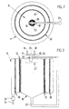
- FIGS. 1, 2 and 3 there are illustrated two versions of an apparatus to at least partially separate a liquid-liquid mixture, the apparatus of Figure 1 having a planar membrane, and the apparatus of Figure 2 being substantially cylindrical with a cylindrical membrane. Like numbers have been used to illustrate like parts.
- the apparatus comprises a first inlet chamber 10 and a second outlet chamber 11. Chambers 10 and 11 are separated by a flexible semi-permeable membrane 12. Chambers 10 and 11 can be evacuated by connection of the chambers to a vacuum source 13 (not shown). Valves 14, 15 are used to regulate the vacuum within chambers 10 and 11. The chambers are designed to operate under pressures of about 25mbar.
- a liquid-liquid mixture which is to be separated passes through inlet 16, the flow rate being regulated by valve 17.
- the liquid-liquid mixture is mixed with a gas passing through conduit 18 which is again controlled by a valve 19.
- the liquid and gas mixtures are passed into an atomising nozzle 20, the rate of which can be determined by valve 21.
- Nozzle 20 atomises the liquid gas mixture and sprays it into chamber 10.
- a conductive micro-mesh screen 22 In front of nozzle 20 and in chamber 10 is located a conductive micro-mesh screen 22. Screen 22 functions to assist in droplet dispersion and assists electric charge/vapour transfer.
- chamber 10 becomes pressurised relative to chamber 11 which results in a pressure differential being formed on each side of membrane 12.
- Any spray which condenses into larger droplets or a liquid can be recycled through conduit 23 back to nozzle 20, the rate of recycle being determined by valve 24.
- the forward part of nozzle 20 is within a vacuum sleeve 25 to allow recycled liquid to pass through conduit 23 and re-emerge into chamber 10 as a spray.
- a support 30 in the form of a conductive mesh or grid is positioned in outlet chamber 11 and slightly spaced from flexible membrane 12.
- Support 30 can be electrically charged as can membrane 12.
- Nozzle 20 can also be electrically charged and in the embodiment, nozzle 20 is negatively charged while membrane 12 is positively charged. The effect of the charge is to facilitate passage of spray droplets towards membrane 12.
- Membrane 12 functions to separate the liquid-liquid mixture and the component which preferentially passes through membrane 12 can be collected in chamber 11 and passed through conduit 31 which is controlled by valve 32.
- atomised inward liquid enters the inlet compartment which is pressurised to approximately 25mbar.
- the reduced pressure in compartment 10 further encourages or promotes reduction of droplet size.
- the outlet compartment 11 is also initially pressurised to approximately 25mbar.
- compartment 10 becomes positively pressurised which causes flexible membrane 12 to deform towards support 30.
- the charged membrane will attract the desired size of molecule to itself.
- the selective permeability of the impregnated compounds and the reduced atmospheric pressure on the outlet side of the membrane will cause the desired molecules to pass through the membrane.
- Support 30 can be electrically charged to further attract molecules out of the membrane.
- Support 30 may also be heated to assist the release through vaporisation of molecules passing through the membrane, and the operating temperature of support 30 can be in the range of 10 - 400°C.
- Liquid passing through the membrane can be collected in reservoirs via pressure-controlled non-return valves, or condensed in cold traps, if desired. Partially separated liquids in the inlet compartment can be recycled to the feed liquid flow via a venturi pick-up until the desired level of separation has been reached.
- Membrane 12 may also be energised electrically to generate heat within its structure, thus encouraging transport of heated molecules through the membrane into the lower pressure outlet compartment.
Landscapes
- Engineering & Computer Science (AREA)
- Water Supply & Treatment (AREA)
- Chemical & Material Sciences (AREA)
- Chemical Kinetics & Catalysis (AREA)
- Separation Using Semi-Permeable Membranes (AREA)
- Photoreceptors In Electrophotography (AREA)
Description
Claims (15)
- A method of separating liquid from a liquid-liquid mixture, the method characterised in that it includes the step of contacting the liquid-liquid mixture against one side of a separating membrane in the form of a spray such that the liquid to be separated preferentially passes through the membrane for collection on the other side of the membrane.
- The method of claim 1 wherein the spray is in the form of an atomised spray or fine droplet spray.
- The method of claim 2 wherein the separating membrane is a semi-permeable membrane.
- The method of claim 3 wherein the membrane is selected from the group consisting of a rigid membrane, a flexible membrane, a rigid perforated ceramic membrane, a rigid perforated metal membrane, a flexible polymer membrane, a semi-permeable silicone rubber membrane, membranes impregnated with zeolite materials, a flexible nitrilebutadiene rubber membrane, a polyisobutylene rubber membrane, a styrenebutadiene rubber membrane.
- The method of claim 3 wherein the membrane is able to be electrically charged.
- The method of claim 2 wherein the liquid-liquid mixture passes through a nozzle to convert it into a spray.
- The method of claim 6 wherein the mixture is mixed with a gas flow prior to passing through the nozzle.
- The method of claim 7 wherein the gas can carry an electric charge.
- The method of claim 1 wherein a pressure differential is provided across the membrane with the higher pressure side being the side which contacts the spray.
- The method of claim 9 wherein a support for the membrane is provided, the support comprising a mesh extending adjacent the outlet side of the membrane.
- The method of claim 10 wherein the support can be electrically charged.
- The method of claim 10 wherein the support can be heated.
- An apparatus for at least partially separating a liquid-liquid mixture, the apparatus comprising a first inlet chamber and a second outlet chamber, a membrane separating the inlet and outlet chambers, and means to convert liquid-liquid mixture into a spray comprising liquid to be separated before contact of the spray with the membrane in the inlet chamber such that the liquid to be separated preferentially passes through the membrane for collection on the other side of the membrane.
- The apparatus of claim 13 wherein the inlet chamber, in use, is of higher pressure than the outlet chamber.
- The apparatus of claim 14 wherein a nozzle converts the liquid-liquid mixture into the spray.
Applications Claiming Priority (4)
| Application Number | Priority Date | Filing Date | Title |
|---|---|---|---|
| AUPM6857A AUPM685794A0 (en) | 1994-07-18 | 1994-07-18 | Method and apparatus for separating liquid-liquid mixtures |
| AUPM685794 | 1994-07-18 | ||
| AUPM6857/94 | 1994-07-18 | ||
| PCT/AU1995/000432 WO1996002316A1 (en) | 1994-07-18 | 1995-07-18 | Method and apparatus for separating liquid-liquid mixtures |
Publications (3)
| Publication Number | Publication Date |
|---|---|
| EP0771232A1 EP0771232A1 (en) | 1997-05-07 |
| EP0771232A4 EP0771232A4 (en) | 1997-10-08 |
| EP0771232B1 true EP0771232B1 (en) | 2001-11-14 |
Family
ID=3781406
Family Applications (1)
| Application Number | Title | Priority Date | Filing Date |
|---|---|---|---|
| EP95924806A Expired - Lifetime EP0771232B1 (en) | 1994-07-18 | 1995-07-18 | Method and apparatus for separating liquid-liquid mixtures |
Country Status (9)
| Country | Link |
|---|---|
| US (1) | US5951871A (en) |
| EP (1) | EP0771232B1 (en) |
| JP (1) | JPH10507123A (en) |
| KR (1) | KR100347687B1 (en) |
| CN (1) | CN1062783C (en) |
| AU (1) | AUPM685794A0 (en) |
| CA (1) | CA2194879A1 (en) |
| DE (1) | DE69523924T2 (en) |
| WO (1) | WO1996002316A1 (en) |
Families Citing this family (9)
| Publication number | Priority date | Publication date | Assignee | Title |
|---|---|---|---|---|
| AUPN629295A0 (en) * | 1995-10-31 | 1995-11-23 | University Of Queensland, The | Method and apparatus for separating liquid mixtures using intermittent heating |
| US6217770B1 (en) * | 1998-08-14 | 2001-04-17 | Atp International | Apparatus and method for treatment of water |
| WO2001080981A1 (en) * | 2000-04-20 | 2001-11-01 | Membrana Mundi Gmbh | Separation of fluid mixtures using membranized sorption bodies |
| ATE527047T1 (en) * | 2005-06-24 | 2011-10-15 | Univ Nanyang Tech | TREATMENT OF CONTAMINATED INFLOW WITH A MEMBRANE DISTILLATION BIOREACTOR |
| AU2006275320B2 (en) | 2005-08-04 | 2012-03-08 | Saban Ventures Pty Limited | Apparatus for concentrating a nebulant |
| KR101524225B1 (en) * | 2014-02-04 | 2015-05-29 | 한국과학기술연구원 | Membrane Distillation Module |
| CN104190273B (en) * | 2014-09-12 | 2016-05-11 | 天津工业大学 | A kind of PVDF-g-PNIPAAm film Thermo-sensitive and hydrophilic preparation method of improving |
| CN113813765B (en) * | 2021-10-19 | 2024-03-12 | 盐城海德能水处理环保工程有限公司 | Phenol-cyanogen wastewater deodorization system and deodorization method thereof |
| CN116223083B (en) * | 2023-02-14 | 2026-02-17 | 合肥通用机械研究院有限公司 | Performance test system for water phase feeding and discharging mechanism |
Family Cites Families (12)
| Publication number | Priority date | Publication date | Assignee | Title |
|---|---|---|---|---|
| US3405058A (en) * | 1964-02-17 | 1968-10-08 | Wendell S. Miller | Purification of water |
| US3827561A (en) * | 1972-09-20 | 1974-08-06 | Milton Roy Co | Deaerator for dialysis system |
| FR2389400B1 (en) * | 1977-05-05 | 1982-01-08 | Seri | |
| JPS59302A (en) * | 1982-06-28 | 1984-01-05 | Asahi Chem Ind Co Ltd | Separation apparatus |
| US5089122A (en) * | 1984-08-31 | 1992-02-18 | Fraunhofer Gesellschaft | Device for the separation of fluid mixtures |
| DE68926421T2 (en) * | 1988-08-20 | 1996-09-12 | Nitto Denko Corp | Process for removing dissolved gases from a liquid |
| US5062927A (en) * | 1990-01-05 | 1991-11-05 | T And G Technologies, Inc. | Method of operating a still |
| US5104810A (en) * | 1990-06-27 | 1992-04-14 | United Technologies Corporation | Zero gravity purge and trap for monitoring volatile organic compounds |
| JPH04290597A (en) * | 1991-03-19 | 1992-10-15 | Hitachi Ltd | water treatment equipment |
| DE4214551C2 (en) * | 1992-04-27 | 1996-06-20 | Geesthacht Gkss Forschung | Method and device for the separation of gas mixtures resulting from liquids |
| KR950013568A (en) * | 1993-11-29 | 1995-06-15 | 미우라 아끼라 | Separation Method of Mixed Liquid by Infiltration Vaporization and Separation Device of Infiltration Vapor Membrane |
| US5464540A (en) * | 1993-12-09 | 1995-11-07 | Bend Research, Inc. | Pervaporation by countercurrent condensable sweep |
-
1994
- 1994-07-18 AU AUPM6857A patent/AUPM685794A0/en not_active Abandoned
-
1995
- 1995-07-18 CN CN95194215A patent/CN1062783C/en not_active Expired - Fee Related
- 1995-07-18 EP EP95924806A patent/EP0771232B1/en not_active Expired - Lifetime
- 1995-07-18 CA CA002194879A patent/CA2194879A1/en not_active Abandoned
- 1995-07-18 WO PCT/AU1995/000432 patent/WO1996002316A1/en not_active Ceased
- 1995-07-18 JP JP8504525A patent/JPH10507123A/en active Pending
- 1995-07-18 KR KR1019970700322A patent/KR100347687B1/en not_active Expired - Fee Related
- 1995-07-18 DE DE69523924T patent/DE69523924T2/en not_active Expired - Fee Related
- 1995-07-18 US US08/765,678 patent/US5951871A/en not_active Expired - Fee Related
Also Published As
| Publication number | Publication date |
|---|---|
| CA2194879A1 (en) | 1996-02-01 |
| DE69523924D1 (en) | 2001-12-20 |
| CN1153483A (en) | 1997-07-02 |
| EP0771232A1 (en) | 1997-05-07 |
| DE69523924T2 (en) | 2002-04-11 |
| KR970704504A (en) | 1997-09-06 |
| AUPM685794A0 (en) | 1994-08-11 |
| KR100347687B1 (en) | 2002-11-29 |
| EP0771232A4 (en) | 1997-10-08 |
| US5951871A (en) | 1999-09-14 |
| JPH10507123A (en) | 1998-07-14 |
| CN1062783C (en) | 2001-03-07 |
| WO1996002316A1 (en) | 1996-02-01 |
Similar Documents
| Publication | Publication Date | Title |
|---|---|---|
| US5951871A (en) | Method and apparatus for separating liquid-liquid mixtures | |
| EP0657205B1 (en) | Pervaporation by countercurrent condensable sweep | |
| JPH08168655A (en) | Countercurrent sweep vapor permeation method | |
| JPH07506371A (en) | Method and apparatus for processing pharmaceutical fluids containing parenteral emulsions | |
| US5030356A (en) | Process for recovering organic components from liquid streams | |
| US5993515A (en) | Apparatus and process for selectively removing a component from a multicomponent aqueous solution by pervaporation | |
| AU2008352310A1 (en) | Method and apparatus for dewatering a mixture of ethanol and water | |
| JPH06508554A (en) | How to recover organic components from liquid waste | |
| US6017439A (en) | Method and apparatus for separating liquid mixtures using intermittent heating | |
| EP0062494A2 (en) | Method and device for separating mixed liquid components | |
| AU681305B2 (en) | Method and apparatus for separating liquid-liquid mixtures | |
| AU2013201349B2 (en) | Membrane stripping process for removing volatile organic compounds from a latex | |
| US4842748A (en) | Methods for removing volatile substances from water using flash vaporization | |
| WO1993022036A1 (en) | Membrane extraction process | |
| JPH11156167A (en) | Membrane separation method and apparatus | |
| AU5657496A (en) | Apparatus and method for reducing the pressure in a volatile organic chemical tank ullage | |
| JP3275978B2 (en) | Gas-liquid separation device | |
| Kokugan et al. | Effects of downstream pressure on pervaporation performance for dilute alcohol solution using porous hydrophobic membranes | |
| JPH08257343A (en) | Removal Method of Volatile Organic Components by Membrane Separation Using Countercurrent Sweep Gas | |
| Mauz et al. | Concentration of native etheric oil aroma components by pervaporation | |
| JPH03109912A (en) | Treatment of gas containing organic vapor | |
| AU3287000A (en) | Method and device of separating substance mixtures in liquid and/or vapour form by pervaporation and/or vapour permeation | |
| Wijmans | FEED CONCENTRATION (ppm) | |
| JPH05309358A (en) | Treatment of tap water | |
| JPH07213804A (en) | Method and apparatus for degassing liquid |
Legal Events
| Date | Code | Title | Description |
|---|---|---|---|
| PUAI | Public reference made under article 153(3) epc to a published international application that has entered the european phase |
Free format text: ORIGINAL CODE: 0009012 |
|
| 17P | Request for examination filed |
Effective date: 19970217 |
|
| AK | Designated contracting states |
Kind code of ref document: A1 Designated state(s): DE GB IT |
|
| A4 | Supplementary search report drawn up and despatched |
Effective date: 19970826 |
|
| AK | Designated contracting states |
Kind code of ref document: A4 Designated state(s): DE GB IT |
|
| 17Q | First examination report despatched |
Effective date: 19990916 |
|
| GRAG | Despatch of communication of intention to grant |
Free format text: ORIGINAL CODE: EPIDOS AGRA |
|
| GRAG | Despatch of communication of intention to grant |
Free format text: ORIGINAL CODE: EPIDOS AGRA |
|
| GRAH | Despatch of communication of intention to grant a patent |
Free format text: ORIGINAL CODE: EPIDOS IGRA |
|
| GRAH | Despatch of communication of intention to grant a patent |
Free format text: ORIGINAL CODE: EPIDOS IGRA |
|
| GRAA | (expected) grant |
Free format text: ORIGINAL CODE: 0009210 |
|
| AK | Designated contracting states |
Kind code of ref document: B1 Designated state(s): DE GB IT |
|
| REF | Corresponds to: |
Ref document number: 69523924 Country of ref document: DE Date of ref document: 20011220 |
|
| REG | Reference to a national code |
Ref country code: GB Ref legal event code: IF02 |
|
| PLBE | No opposition filed within time limit |
Free format text: ORIGINAL CODE: 0009261 |
|
| STAA | Information on the status of an ep patent application or granted ep patent |
Free format text: STATUS: NO OPPOSITION FILED WITHIN TIME LIMIT |
|
| 26N | No opposition filed | ||
| PGFP | Annual fee paid to national office [announced via postgrant information from national office to epo] |
Ref country code: GB Payment date: 20040714 Year of fee payment: 10 |
|
| PGFP | Annual fee paid to national office [announced via postgrant information from national office to epo] |
Ref country code: DE Payment date: 20040729 Year of fee payment: 10 |
|
| PG25 | Lapsed in a contracting state [announced via postgrant information from national office to epo] |
Ref country code: IT Free format text: LAPSE BECAUSE OF NON-PAYMENT OF DUE FEES Effective date: 20050718 Ref country code: GB Free format text: LAPSE BECAUSE OF NON-PAYMENT OF DUE FEES Effective date: 20050718 |
|
| PG25 | Lapsed in a contracting state [announced via postgrant information from national office to epo] |
Ref country code: DE Free format text: LAPSE BECAUSE OF NON-PAYMENT OF DUE FEES Effective date: 20060201 |
|
| GBPC | Gb: european patent ceased through non-payment of renewal fee |
Effective date: 20050718 |