EP0771131A2 - Echtzeitverarbeitung von virtuellen Verbindungen in Paketvermittlung - Google Patents
Echtzeitverarbeitung von virtuellen Verbindungen in Paketvermittlung Download PDFInfo
- Publication number
- EP0771131A2 EP0771131A2 EP96307640A EP96307640A EP0771131A2 EP 0771131 A2 EP0771131 A2 EP 0771131A2 EP 96307640 A EP96307640 A EP 96307640A EP 96307640 A EP96307640 A EP 96307640A EP 0771131 A2 EP0771131 A2 EP 0771131A2
- Authority
- EP
- European Patent Office
- Prior art keywords
- packet
- cell
- data
- switch
- state
- Prior art date
- Legal status (The legal status is an assumption and is not a legal conclusion. Google has not performed a legal analysis and makes no representation as to the accuracy of the status listed.)
- Ceased
Links
- 238000012545 processing Methods 0.000 title claims abstract description 11
- 238000000034 method Methods 0.000 claims abstract description 16
- 230000006870 function Effects 0.000 claims description 64
- 230000005540 biological transmission Effects 0.000 claims description 14
- 230000008901 benefit Effects 0.000 abstract description 3
- 210000004027 cell Anatomy 0.000 description 138
- 208000037820 vascular cognitive impairment Diseases 0.000 description 71
- 102100036409 Activated CDC42 kinase 1 Human genes 0.000 description 11
- 230000011664 signaling Effects 0.000 description 9
- 230000000737 periodic effect Effects 0.000 description 6
- 238000012423 maintenance Methods 0.000 description 5
- 238000007726 management method Methods 0.000 description 4
- 230000007704 transition Effects 0.000 description 4
- 238000013459 approach Methods 0.000 description 3
- 238000004422 calculation algorithm Methods 0.000 description 3
- 238000004364 calculation method Methods 0.000 description 3
- 238000012360 testing method Methods 0.000 description 3
- 230000009471 action Effects 0.000 description 2
- 230000006727 cell loss Effects 0.000 description 2
- 230000004048 modification Effects 0.000 description 2
- 238000012986 modification Methods 0.000 description 2
- 230000001360 synchronised effect Effects 0.000 description 2
- PCTMTFRHKVHKIS-BMFZQQSSSA-N (1s,3r,4e,6e,8e,10e,12e,14e,16e,18s,19r,20r,21s,25r,27r,30r,31r,33s,35r,37s,38r)-3-[(2r,3s,4s,5s,6r)-4-amino-3,5-dihydroxy-6-methyloxan-2-yl]oxy-19,25,27,30,31,33,35,37-octahydroxy-18,20,21-trimethyl-23-oxo-22,39-dioxabicyclo[33.3.1]nonatriaconta-4,6,8,10 Chemical compound C1C=C2C[C@@H](OS(O)(=O)=O)CC[C@]2(C)[C@@H]2[C@@H]1[C@@H]1CC[C@H]([C@H](C)CCCC(C)C)[C@@]1(C)CC2.O[C@H]1[C@@H](N)[C@H](O)[C@@H](C)O[C@H]1O[C@H]1/C=C/C=C/C=C/C=C/C=C/C=C/C=C/[C@H](C)[C@@H](O)[C@@H](C)[C@H](C)OC(=O)C[C@H](O)C[C@H](O)CC[C@@H](O)[C@H](O)C[C@H](O)C[C@](O)(C[C@H](O)[C@H]2C(O)=O)O[C@H]2C1 PCTMTFRHKVHKIS-BMFZQQSSSA-N 0.000 description 1
- 101000741965 Homo sapiens Inactive tyrosine-protein kinase PRAG1 Proteins 0.000 description 1
- 102100038659 Inactive tyrosine-protein kinase PRAG1 Human genes 0.000 description 1
- 210000004460 N cell Anatomy 0.000 description 1
- 230000003190 augmentative effect Effects 0.000 description 1
- 210000003719 b-lymphocyte Anatomy 0.000 description 1
- 230000008859 change Effects 0.000 description 1
- 238000006243 chemical reaction Methods 0.000 description 1
- 230000003247 decreasing effect Effects 0.000 description 1
- 230000001934 delay Effects 0.000 description 1
- 230000002452 interceptive effect Effects 0.000 description 1
- 230000000873 masking effect Effects 0.000 description 1
- 230000007246 mechanism Effects 0.000 description 1
- 239000010813 municipal solid waste Substances 0.000 description 1
- 230000006855 networking Effects 0.000 description 1
- 238000004088 simulation Methods 0.000 description 1
- 238000013519 translation Methods 0.000 description 1
- 230000001960 triggered effect Effects 0.000 description 1
Images



Classifications
-
- H—ELECTRICITY
- H04—ELECTRIC COMMUNICATION TECHNIQUE
- H04L—TRANSMISSION OF DIGITAL INFORMATION, e.g. TELEGRAPHIC COMMUNICATION
- H04L49/00—Packet switching elements
- H04L49/30—Peripheral units, e.g. input or output ports
- H04L49/3081—ATM peripheral units, e.g. policing, insertion or extraction
-
- H—ELECTRICITY
- H04—ELECTRIC COMMUNICATION TECHNIQUE
- H04L—TRANSMISSION OF DIGITAL INFORMATION, e.g. TELEGRAPHIC COMMUNICATION
- H04L12/00—Data switching networks
- H04L12/02—Details
- H04L12/16—Arrangements for providing special services to substations
- H04L12/18—Arrangements for providing special services to substations for broadcast or conference, e.g. multicast
- H04L12/1863—Arrangements for providing special services to substations for broadcast or conference, e.g. multicast comprising mechanisms for improved reliability, e.g. status reports
- H04L12/1877—Measures taken prior to transmission
-
- H—ELECTRICITY
- H04—ELECTRIC COMMUNICATION TECHNIQUE
- H04L—TRANSMISSION OF DIGITAL INFORMATION, e.g. TELEGRAPHIC COMMUNICATION
- H04L49/00—Packet switching elements
- H04L49/20—Support for services
- H04L49/201—Multicast operation; Broadcast operation
-
- H—ELECTRICITY
- H04—ELECTRIC COMMUNICATION TECHNIQUE
- H04L—TRANSMISSION OF DIGITAL INFORMATION, e.g. TELEGRAPHIC COMMUNICATION
- H04L49/00—Packet switching elements
- H04L49/20—Support for services
- H04L49/201—Multicast operation; Broadcast operation
- H04L49/203—ATM switching fabrics with multicast or broadcast capabilities
-
- H—ELECTRICITY
- H04—ELECTRIC COMMUNICATION TECHNIQUE
- H04L—TRANSMISSION OF DIGITAL INFORMATION, e.g. TELEGRAPHIC COMMUNICATION
- H04L49/00—Packet switching elements
- H04L49/20—Support for services
- H04L49/205—Quality of Service based
- H04L49/206—Real Time traffic
-
- H—ELECTRICITY
- H04—ELECTRIC COMMUNICATION TECHNIQUE
- H04L—TRANSMISSION OF DIGITAL INFORMATION, e.g. TELEGRAPHIC COMMUNICATION
- H04L49/00—Packet switching elements
- H04L49/30—Peripheral units, e.g. input or output ports
- H04L49/3009—Header conversion, routing tables or routing tags
-
- H—ELECTRICITY
- H04—ELECTRIC COMMUNICATION TECHNIQUE
- H04Q—SELECTING
- H04Q11/00—Selecting arrangements for multiplex systems
- H04Q11/04—Selecting arrangements for multiplex systems for time-division multiplexing
- H04Q11/0428—Integrated services digital network, i.e. systems for transmission of different types of digitised signals, e.g. speech, data, telecentral, television signals
- H04Q11/0478—Provisions for broadband connections
-
- H—ELECTRICITY
- H04—ELECTRIC COMMUNICATION TECHNIQUE
- H04L—TRANSMISSION OF DIGITAL INFORMATION, e.g. TELEGRAPHIC COMMUNICATION
- H04L12/00—Data switching networks
- H04L12/54—Store-and-forward switching systems
- H04L12/56—Packet switching systems
- H04L12/5601—Transfer mode dependent, e.g. ATM
- H04L2012/5619—Network Node Interface, e.g. tandem connections, transit switching
-
- H—ELECTRICITY
- H04—ELECTRIC COMMUNICATION TECHNIQUE
- H04L—TRANSMISSION OF DIGITAL INFORMATION, e.g. TELEGRAPHIC COMMUNICATION
- H04L12/00—Data switching networks
- H04L12/54—Store-and-forward switching systems
- H04L12/56—Packet switching systems
- H04L12/5601—Transfer mode dependent, e.g. ATM
- H04L2012/5638—Services, e.g. multimedia, GOS, QOS
- H04L2012/5639—Tariffs or charging
-
- H—ELECTRICITY
- H04—ELECTRIC COMMUNICATION TECHNIQUE
- H04L—TRANSMISSION OF DIGITAL INFORMATION, e.g. TELEGRAPHIC COMMUNICATION
- H04L12/00—Data switching networks
- H04L12/54—Store-and-forward switching systems
- H04L12/56—Packet switching systems
- H04L12/5601—Transfer mode dependent, e.g. ATM
- H04L2012/5638—Services, e.g. multimedia, GOS, QOS
- H04L2012/5646—Cell characteristics, e.g. loss, delay, jitter, sequence integrity
- H04L2012/5652—Cell construction, e.g. including header, packetisation, depacketisation, assembly, reassembly
Definitions
- This invention relates to connection oriented networks and real time processing in packet switches to support high speed multicasting.
- ATM switches can be classified into three categories: basic switches, smart switches, and intelligent switches.
- Basic switches perform preliminary switching functions and sometimes operate in the hundreds of Gb/s throughput region with multi-Gb/s port rates. However, they cannot support multicast, transmission from a source host to a selected group of more than one destination hosts, or other special functions, for the reasons discussed below.
- Many commercially available ATM switches fall into this category.
- Intelligent switches on the other hand, suffer from technological limitations associated with being software based, and therefore cannot operate in real time, except for lower-throughput switches. (Routers, most of which operate below 100 Mb/s, are one example of intelligent switches.)
- ATM switches which fall into the smart switch category, support multicast and broadcast transmission from a source host to all hosts on a specified network. These switches can operate in the tens of Gb/s throughput region with port rates in the hundreds of Mb/s.
- a source switch To support multicast, a source switch must be able to receive an acknowledgment ("ACK”) from each multicast destination switch. Thus to achieve reliable delivery in a multicasting environment the source host must be capable of processing the ACKs for a potentially large number of destinations. When the source system receives more ACKs than it can manage, a situation known as 'ACK implosion' results and system efficiency suffers.
- ACK acknowledgment
- Protocols have been proposed at higher layers, including transport through application levels, that provide processing to support a 'combine function' in which ACKs, for example, are combined logically before being passed to the source application. See for example, U.S. Patent No. 5,541,927 issued to Kristol et al., on July 30, 1996 which describes a method for a high speed multicast protocol.
- the combine function would be located at the branches along the multicast tree so that the source would not be inundated with messages.
- real time state and combinatorial logic is added to the packet switch hardware at the ATM protocol layer, such that the switches provide general purpose primitives to support applications including signaling, maintenance, wireless networking, games, software distribution, synchronization, telemetry and computing.
- the memory in the VCI lookup table of apacket switch is extended and arithmetic logic unit (ALU) functionality is added to the header processing circuitry to support a packet switch instruction set.
- ALU arithmetic logic unit
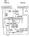
- FIG. 1 shows an illustrative architecture for hardware primitives designed in accordance with the principles of the invention.
- FIG. 2 illustrates a combination of virtual channel identifiers that define a cell stream.
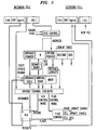
- FIG. 3 shows an illustrative hardware architecture in which the operand and opcode fields of a look-up table are replaced with an operand pointer to a separate operand table and an opcode pointer to a separate opcode table, respectively.
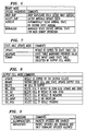
- FIGs. 4 to 9 show instruction sets and instruction set fields, that are executed by the processor of a packet switching system to implement the principles of the invention.
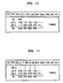
- FIG. 10 shows the respective format of illustrative status packets periodically broadcast from each multicast destination.
- FIG. 11 illustrates a modified status packet designed to simplify opcode computations.
- FIGs. 12A and 12B illustrate binary computations performed on status packets to support retransmission in a packet switching system implementing the principles of the invention.
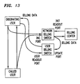
- FIG. 13 illustrates a switch architecture using the primitives of the present invention to implement a billing application.
- cells using the primitive services in the switch in accordance with the present invention have a special format.
- the data portion of cell 110 contains an opcode field 111, an operand field 112, a CRC field 113, and an optional data (comment) field114.
- the opcode found in opcode field 111 specifies the operation to be performed while the operand field 112 may contain one or more pieces of data that may enter the computation.
- the CRC in CRC field 113 is provided because there is no error protection at the ATM level. A simple CRC calculation is performed over the opcode and operand before completing the calculation. The function is aborted with no change when a CRC error is detected. Cell losses are handled at a higher level and are discussed further below.
- a computation is performed in ALU 130 and operand state 121 or operand field 142 in outgoing cell 140, or both, are updated with the result.
- ALU 130 sets and passes flags to-flag control unit 150 based on the results of the computation. Depending on the flag control word, outgoing cell 140 may be deleted or updated with the result.
- outgoing cell 140 includes the same fields as incoming cell 110, namely, opcode field 141, CRC field 143, comment field 144 and VCI field 145.
- the opcode entered in ALU 130 can come from one of two sources: the opcode portion 123 of lookup table 120 or opcode field 111 of incoming cell 110. Signaling software is used to update the opcode in lookup table 120 while the opcode in cell 110 is inserted by the virtual channel user.
- Opcode control circuitry 160 uses lookup table 120 opcode bits or additional permission bits to select whether opcodes will be accepted from incoming cell 110 or whether only the opcodes from lookup table 120 will be used. Once the opcode source has been selected, opcode control circuitry 160 generates the ALU control word that selects the ALU operation and generates the flag control word that selects the flag control function.
- VCI control 170 facilitates this by forcing the least significant digit of the VCI of all incoming packets being combined to the same value, either zero or one. Since two consecutive VCIs differ only in the least significant digit, the VCI control 170 function will always result in the VCI of the operand stored in lookup table 120 allowing it to be retrieved and input to ALU 130.
- VCI information from VCI field 115 in incoming cell 110, controlled by VCI control 170 may also be used to modify the opcode function and the bits found in arrival state field 122 as described below.
- Routing field 124 and Quality-of-Service (QoS) field 125 are used in the traditional fashion in the ATM switch to route and schedule outgoing cell 140 at the appropriate output port of the switch.
- QoS Quality-of-Service
- the translation of VCI field 115 may occur in the output section of the line card of the switch.
- the hardware described above can be used to compute functions over cells in a single VCI stream or over cells from multiple VCI streams.
- the operands from one or more cells are used to compute a result.
- unary VCI functions involve three general steps: initialization, computation, and retrieving the result.
- the initialization can be performed at call setup by the signaling software or through cell opcodes, and the initialization is usually a copy of the operand field of the cell to the operand field in the lookup table so that it is set to a known value.
- the computation is performed by sending one or more cells to the switch with suitable opcodes and operands.
- the results of the operations are accumulated in the operand field of the lookup table.
- the result accumulated in the operand field of the state table can be copied to the output cell and sent to its destination.
- the result of each intermediate and the final calculation can be forwarded to the destination during each computation, thereby eliminating the last step.
- VCI A For example, suppose a dozen nodes that must perform maintenance functions, e.g., distribution of table or software updates, under the control of a network manager.
- the manager establishes VCI A from each node to a switch and continues the inverse multicast connection from the switch to itself. It also establishes a connection from itself to the switch on VCI A, which it uses to initialize the operand state to 0.
- On a separate VCI it multicasts the command to have the nodes perform the first maintenance step of the function.
- the nodes send a cell on VCI A with the OR opcode and with an operand containing a unary representation of their station id (e.g., station zero sets bit zero, station one sets bit one).
- the manager After a suitable time period, the manager sends an opcode on VCI A to copy the result to an output cell, which it then receives and uses to verify that all stations have completed the maintenance function. The manager can then take action for any stations that failed to respond, and can then continue with the next maintenance function.
- the hardware described above can also be used to compute functions over multiple VCI streams with only a modest increase in complexity. To support an arbitrary number of VCIs in a combine function, it is sufficient to support computation over two streams since larger numbers of streams can be combined using computations on pairs of VCIs in a hierarchical fashion.
- FIG. 2 as an illustration, cells from stations A and B are combined in switch 201 while cells from stations C and D are combined in switch 202. Finally, the result from switches 201 and 202 are combined in switch 203.
- Switch 201 shown with two state arrival fields is set to register an arrival state bit with a value 1 in its right field for the packet from station B, when it arrives, and an arrival state bit with a value 1 in its left field for the packet from station A, when it arrives.
- a similar set-up is illustrated for switch 202 and switch 203.
- VCI control 170 causes the lookup of operands from both A and B to access the same operand state table by ignoring the VCI LSB.
- the LSB is used, however, to update a separate two-bit state field on an arrival of a cell.
- 0,0 indicates no cell has arrived; 1,0 indicates one cell has arrived from A; 0,1 indicates one cell from B; or 1,1 indicates both cells have arrived.
- the system either disables itself staying in state 1,1 after issuing the combined result, or it issues the result and clears itself to state 0,0 waiting for the next operation. If the system disables itself in the 1,1 state, a separate instruction must be issued (multicast if a hierarchy) to reset the state to 0,0 for the next operation.
- VCIs assigning adjacent VCIs is impossible or otherwise impractical common VCIs can be used while ensuring uniqueness of incoming cells with a separate bit in the data field to distinguish between the two incoming cells.
- a level of indirection can be added to the operand field, eliminating any special requirements on the VCI relationship (at perhaps a speed penalty).
- a level of indirection means using a pointer to a table rather than looking up a table directly.
- the extra level of indirection can reduce the total amount of memory needed to support these functions when the majority of the virtual channels do not use the ALU.
- the indirection reduces the VCI operand table 320 to a few pointer bits in pointer field 321. More specifically, if C max is the maximum number of active VCIs using the ALU, V max the maximum number of active VCIs, M max the maximum number of VCIs in a combine function, and O size the operand size, the size of the pointer field 321 in the VCI lookup table 320 is V max • [log 2 C max + log 2 M max ] log rounded up to the next highest integer, and the size of the operand lookup table 360 is C max • (O size + 2M max ).
- opcode field By including the opcode field in lookup table 360, additional space can be saved. However, if the operand field remains in the VCI lookup table 320, separate VCIs can have separate instructions associated with them providing further programming flexibility. It is also possible to add a level of indirection to the opcode field using opcode pointer 323 and opcode lookup 330 which would enable separate VCIs to have different operands and permissions while also reducing the total memory requirements to C max •O size from V max •O size without indirection. Note, this would be advantageous if the number of possible instructions is greater than the number of active VCIs.
- arrival state 350 is included in the operand lookup table 360.
- a small integer descriptor numbered sequentially in binary is uniquely identified with each VCI associated with the combine function.
- the binary integer descriptor M is obtained from field 322 of lookup table 320, converted to a unary number in binary-unary unit 310, and used to update arrival state field 350 in the operand lookup table 360 by indicating which cell has arrived.
- the arrival state contains all zeros, no cells have arrived and the currently arriving cell must copy its operand to operand field 380.
- the operand from cell 110 When some, but not all of the cells have arrived, the operand from cell 110 must be combined with the operand in operand field 380 and written back to operand field 380.
- the final cell When the final cell arrives, all ones in arrival state field 350, for example, the cell and operand fields 112 and 380, respectively, are combined and the result written into operand field 142 of outgoing cell 140.
- the no-arrival state and final-arrival state can be decoded with NOR and AND gates, respectively.
- the hardware may support more VCI streams in a combine than a given application needs.
- Suitable masking or maximum VCI count information must also be stored in mask block 340 of lookup table 360 at call setup so that the hardware knows how to compute the final-arrival state.
- the mask field 340 indicates the number of cells to be combined. This is done by stripping off a number of arrival state bits from the maximum number of cells that the switch can combine until the number of remaining bits correspond to the number of cells that need to be combined.
- a binary-to-unary conversion of the unused VCIs can be used to generate a mask that can be OR'ed with the arrival status for proper operation in these cases.
- the notation S refers to the contents of the state operand field stored for a given VCI.
- the notation I is the contents of the immediate operand field following the instruction opcode in an incoming cell. The destination of these operations will be discussed shortly. All arithmetic operations set flag bits that can participate in conditional operations.
- the SOP opcode specifies that the opcode inserted into the opcode portion of the state table be used instead of the opcode found in the incoming cell.
- the operands can be either integer (int) or unsigned integer (uint).
- the arithmetic operations above can be used to combine the contents of two cells from different VCIs to form a result.
- N-ARY the operation is referred to as N-ARY.
- BINARY mode operation requires that the information from each cell arrive together and be combined. Since it is not likely that two sources will be synchronized so that their cells arrive at a packet switch together, as explained above, the state from the cell that arrives first is stored in S while the second arrival causes the computation using the stored value S and the immediate value I from the operand field of the cell. State bits as listed in FIG. 5 track the arrival state 122 of the connections for the binary combine operations of FIG. 1 or N-ARY combine operations of FIG. 3.
- the opcode functions can be modified by control bits.
- the control bits can be part of the opcode of the incoming cell or can be saved as part of the state register by signaling software or by a CPY instruction.
- One bit determines the disposition of a second cell arrival on one input as in a second A cell, before any B cells are received. S can either be updated with the duplicate cell, or the duplicate cell can be dropped.
- the arrival state can automatically switch from the BOTH_ARRIVED state to NEITHER state allowing the next round of BINARY combination to occur or it can stay in the BOTH_ARRIVED state until an RSTAS instruction listed in FIG. 4, is received and the arrival states are reset.
- it is desireable to clear a state and prepare to receive new information. This is referred to as endpoint synchronization.
- Using an RSTAS function allows for endpoint synchronization.
- a single bit can be included in the opcode field to specify that the result of a non BINARY mode ALU operation be used to update the state table.
- the state table In BINARY mode, the state table must be loaded on the first arrival and will be overwritten in later rounds.
- Additional bits in the opcode field can specify whether the operation is in the BINARY mode and determine whether an output cell is generated. Based on the result of flags from arithmetic operations, an output cell can be conditionally generated with the result, as specified in FIG. 8.
- the signaling channel can store an opcode into the state memory, and the security state can be set through the signaling channel as in FIG. 9.
- SOP state opcode instruction
- the opcode field is ignored and the opcode stored in the state table of FIG. 7 is always used.
- INC the INC instruction
- Additional instructions which may be useful include: conditional operations; logical and arithmetic shift instructions; floating point support; billing support instructions; a binary mode instruction that concatenates subfields of the operand fields of the two cells. Additional instructions could access or combine data corresponding to the internal switch state other than data from the state table, e.g., queue length, with packet data and modify the internal state, e.g., switch service policy, directly or conditionally.
- cell-based ALU computation is illustrated below by way of an example drawn from the field of transport protocols.
- cell based ALU computation is more than a mechanism for implementing a specific transport protocol or for protocols in general, protocols are as natural a use of the cell-based computation as number crunching has been to mainframes. But, much as mainframes support databases, games, graphics and interactive computing the network ALU units described herein have a general utility as discussed further below.
- One important application of the primitives discussed above is support of reliable multicasting protocols as discussed below.
- a hierarchy of local processing nodes perform a combine function in accordance with the present invention.
- the primitives discussed above are included in the hardware of a packet switch and the combine function is executed in real time obviating the need to go up and back down the protocol stack at the intermediate combining switch centers.
- the combine function can be applied at the branches of the multicast tree where it will be most effective. Implementation in hardware allows high throughout and low delay by processing the cells in real time.
- the high speed multicast protocol described in U.S. Patent No. 5,541,927 can be implemented with the hardware primitives of the present invention for real time switching application.
- a hierarchical combine tree is established at call setup time to transmit the ACKs from all multicast receivers to the switch ALU units where they are combined pairwise using a binary combine function as described above until eventually a single summary cell is available for transmission to the source.
- the ACK state information is transmitted independently and periodically by each multicast receiver, no special synchronization is needed between the ACK streams.
- the self-clearing binary mode where the ALU resets itself for the next cell from each input VCI as soon as it has computed and sent the current result from the two most recent pairs can be used.
- the combined result never gets transmitted to the source until the next period when the periodic status from the missing cell is retransmitted completing the arguments for the combine function. This will cause a time skew in the combined status information to the source. For example, if A, B, and C arrive and D is lost, no combined cell is generated. Later, if the cells from the subsequent periodic transmission arrive in the sequence A, B, D, C, then the result ABCD will be generated following the arrival of D using the old status of C. This means that the new status from C will not be looked at until the next combine function. Further, if C is always last, perhaps because it has the longest path, then its status will always be late by one periodic status interval.
- each receiver periodically transmits its state based on its own clock. Therefore, although periodic transmissions may all occur at a nominal rate, they are not synchronized and the phases of their transmissions will slide through each other. Thus, any skews built up as a result of a lost cell as outlined above will quickly dissipate and status updates will remain within a few periodic transmission intervals of each other.
- missing cells can be deleted from a combine function.
- a source can initiate, with a multicast, the transition from the disabled 1,1 state to the enabled 0,0 state while notifying each station with the comment field of the same cell to transmit their status.
- the source station can quickly detect cell loss when the combine packet doesn't arrive within a specified period of time.
- only limited pipelining can be achieved using this method making its use with long round trip delays slower than the method outlined above.
- FIG. 10 the format of status cell 1010 periodically broadcast from each multicast destination is shown.
- destination refers to the destination of the original data cell.
- the multicast destinations are actually the source of status cell 1010 to be combined and sent to the source of the original data cell.
- a description of the fields of status cell 1010 can be found in U.S. Patent No. 5,541,927 hereby incorporated by reference as if fully set forth herein.
- the VCI, SEQ, K, Error Check and EPI fields 1011, 1012, 1013, 1014, 1018 and 1019, respectively, can be treated as comments.
- Buff_Avail field 1017 of status cell 1010 is transmitted by each destination. To prevent buffer overrun, the source needs the minimum of this field over all destinations.
- List of Outstanding Blocks (“LOB”) field 1016 is a bitmap of the data blocks successfully received at the destination, while LW r field 1015 gives the block number of the LSB of the LOB field 1016. In other words, LW r 1015 anchors the bitmap and gives the first block number not yet successfully received. The source uses this information to determine which blocks to selectively retransmit and to adjust its transmission rate.
- LOB List of Outstanding Blocks
- the multicast branches must combine the LOB bitmaps in such a way that it has the AND (assuming 0 represents 'not received' and 1 represents 'received') of each of the LOBs properly shifted such that the bit maps are aligned with the first bit of each LOB having the same block number. Variations on the protocol replace AND with the OR function.
- each independent field may preferably be carried on separate streams. Since Buff_Avail field 1017 is logically independent of LOB 1016, Buff_Avail cells travel on a VCI different from the LOB combine function. LOB field 1016, however, is not independent of LW r field 1015. Note that with protocols where suitable coordination in time exists, this can be relaxed and the same VCIs can be used for multiple combines.
- each destination uses the hierarchical tree discussed above to compute the MIN function over all status cells from the destination hosts.
- each destination uses the hierarchical tree discussed above to compute the MIN function over all status cells from the destination hosts.
- each destination uses the hierarchical tree discussed above to transmit its Buff_Avail field as an operand.
- the first arrival of each pair gets stored in a switch state table while the second cell causes the minimum of the stored and received operand to be transmitted to the next level in the tree.
- the source will receive the minimum over all destinations.
- LW r field 1015 and LOB field 1016 are not independent and must be transmitted together.
- LW r indicates the starting position of LOB. For example, if the value in LW r field 1015 is 123 and LOB 1016 contains 01011100, the indication is that blocks 123, 125, 129 and 130 have not been received, where the bitmap in LOB corresponds to increasing block numbers from left to right. Thus, if there are two status messages with different LW r s, the LOBs need to be aligned by shifting one of them as many positions to the left, or right if the LOBs need to be ORed, as the difference between the LW r s.
- the LOBs can be combined in hardware as follows: First, the ALU operand and opcode fields are extended to handle large multi-field operands.
- the opcode function to perform the combine function includes taking the difference between the LW r fields 1015 of the respective cells and shifting one or both of the respective LOB fields 1016 until they are aligned. Next, the respective LOB fields 1016 are ANDed. The ANDing result is transported with the smaller of the two respective LW r fields 1015.
- LOB 1016 is divided into a plurality of equal size windows. For example, if the LOB is 64 bits and a window is 4 bits, there are 16 windows. The first window in a LOB is denoted by Win # field 1111. Thus, LW r 1015 is effectively replaced with Win #1111. Using Win #1111 results in an integer representation requiring less bits than LW r field 1015. Now, instead of transmitting LW r and LOBs starting from the LW r , Win # and LOB blocks are transmitted with fixed boundaries. Note that two status messages can have the same Win # but not necessarily the same LW r .
- the LW r s in the two status messages may vary by as much as A- 1 but still have the same Win #.
- the LOBs can be directly ANDed without any shifting, which would be necessary if the alignment were done based on LW r s as in the original protocol.
- each destination host is expected to transmit the Win # field 1111 and the bitmap of the corresponding window in each cell.
- the destination advances to and transmits the next window.
- the combine opcode first compares the Win #s, and the LOB of the smaller Win # together with the Win # is copied to the result cell. If the Win #s are equal, then the Win # and the AND of the two LOBs are copied to the result cell.
- LOB 1112 As an illustration, suppose the size of LOB 1112 is 16, the size of a window is 4, LW r s for two destinations A and B are 4 and 7, respectively, and the LOBs for A and B are, respectively, 0100 1101 1001 1100 and 0 1001 0100 1010 111.
- A gives the LOB for blocks between 4 and 19 and B gives the LOB for blocks between 7 and 22.
- LOB of B would be aligned with that of A by shifting its LOB 3 bits to the right and then ANDed to produce 0100 1001 0000 1000 and the combined LW r would be 4 (minimum of the two LW r s).
- Win # for both A and B the Win # is 1 since Win # 0 extends from 0 - 3 and Win # 1 corresponds to blocks 4 - 7, and the LOB transmitted would be 0100 1101 1001 1100 and 1110 1001 0100 1010, respectively.
- the three left-most bits of the LOB of B are ls, indicating that B has received blocks 4, 5, and 6. Since the Win # is the same, the combine function will simply AND the bitmaps, resulting in 0100 1001 0000 1000, which is exactly the same as in the original protocol. The combined Win # will be 1. However, the new scheme will produce slightly worse results if the LW r s of A and B belong to different windows.
- Billing i.e., tallying the amount of network resources expended by a VCI is another illustrative application for the ALU-based switch of the present invention.
- a user's cell stream from originating user 1310 to called user 1320 is multicast to a network billing switch 1330 implementing the primitives of the present invention.
- the state table opcode for delete on no overflow INC with DEL_NOVF with permissions NOPACKETOPS.
- Each cell of the originating user's data which can be arbitrary, increments the state S and is deleted.
- Upon overflow a cell is copied out of the ALU of switch 1330 and sent to centralized computers 1350 that can tally this slower-rate signal easily. For reliability, the stream could be multicast to several locations, thereby increasing the redundancy.
- Another method of billing would be to poll and reset the state periodically. This could be accomplished through the signaling network by suitably modifying the state opcode.
- Binary mode billing instructions could offer very powerful methods for computing and summarizing billing information for both the provider and the user.
- a new binary instruction that would not need synchronization could operate so that cells entering one 'protected' port would increment the state while cells in a second 'secure' port would trigger a readout of the state.
- the existing opcodes can provide this capability if modification in the hardware extensions section that allows separate opcodes to be associated with different VCIs are made available.
- a central billing server could multicast a readout-trigger cell to a group of counters, perhaps belonging to one account, and receive the summarized results in return. These results could also be made available to the user through user billing switch 1340 which acts as a user readout port.
- the network writes the billing information into another node's operand state table using CPYI while the user can read that operand state table with a CPYS command.
- the user could also trash the operand state table, but that would not be too useful and would not hurt the network's billing operations.
- timeouts can be implemented at the source station by transmitting a cell after a predefined time, to flush the state of a combine up to that time.
- the timeouts are implemented at the source station because it may not be practical to maintain timers for each VCI at the switch and to invoke operations including cell transmissions upon expiration of the timer.
- the host at the root of a multicast tree can maintain a timer and trigger events in the switch by sending a cell with a suitable opcode and VCI to the switch to flush the state by causing the switch to issue a cell computed from the saved state.
- This is useful for counting the cell arrivals in an interval, for example. It may be possible to have, for example, a state machine cycle through all of the state memory space testing or decrementing locations marked as timed. And, in some architectures it may not be unreasonable to queue a cell for transmission. However, the ALU or other logic would have to generate the CRC and pad out the cell while handling all current traffic.
- the binary tree as described in the protocol example above offers one method of synchronizing single cells. Another method generates the differences between two streams with the CPYAS (set arrival state and copy arrival state to output if both arrived) in self-clearing mode.
- the cells in the difference stream specify which cell of the two streams arrived first and can be used as source feedback, as in a phased locked loop, to align one stream with another.
- Multiple sources can send cells on a VCI with an AND opcode and an all 1s operand field except for a zero bit whose position represents the source identification.
- the state in the switch will be all zero when all sources have sent their cells and the result is multicast back to all source hosts.
- each source periodically repeats transmissions until they receive the multicast reply. At that point, all source hosts announce that they have reached their synchronization point.
- Network management is another application that can take advantage of the combination of status messages within a switch.
- One important function of network management is called Fault management, in which the Network Manager ("NM") tries to locate a faulty element in the network.
- Fault location can be done in several ways. For example, the network manager may collect status from all the network elements at regular intervals and analyze them or let the network elements inform the NM only when there is a fault in the network.
- each network element sends its status periodically to the NM.
- the NM would receive a single combined status message from the distributed resources that it is managing. Each distributed resource would transmit a '1' when it is operational and a '0' when it is unavailable. The combined AND is transmitted to the NM. If the NM receives a '0', a fault location algorithm is triggered.
- the resource could fail completely, e.g. due to fire, earthquake, or loss of battery power, and no status information would be transmitted by that resource.
- the NM would not receive a status message.
- a binary search of the tree can be performed to locate the missing status cell. This can be achieved by sending a test status message from the NM to each input at the level in question. The combined state will be released to the NM if the test status cell enters the port on the side of the tree associated with the failure but will not be released if it enters the operational side of the tree.
- the NM has to explicitly search for the failed network element. It would be quite efficient if the NM is informed not only of a failure but also the identity of the failed element at the same time so that the NM does not have to trigger a fault location algorithm explicitly. This can be accomplished with a simple variation in the framework of our architecture.
- the modified scheme can be described as follows. Consider an intermediate node combining the status of two network elements A and B. If the element B is down, it will not send its status to the intermediate node. However, A will periodically send its status.
- the state in the lookup table of the switch (corresponding to the intermediate node) can keep a count of successive status messages from A and send out a cell containing the ID of B in the comment field of the cell when the count exceeds a certain threshold. In this way, the NM will not only be informed of a failure in the network but it will also know the ID of the failed element in the network.
- each voice sample in a data stream can be transmitted on a VCI with the sample data contained in the operand field.
- the switch can then compute an addition over the samples from different users and output the sum to all users, i.e., giving the bridged voice output.
Landscapes
- Engineering & Computer Science (AREA)
- Computer Networks & Wireless Communication (AREA)
- Signal Processing (AREA)
- Quality & Reliability (AREA)
- Data Exchanges In Wide-Area Networks (AREA)
Applications Claiming Priority (2)
| Application Number | Priority Date | Filing Date | Title |
|---|---|---|---|
| US590895P | 1995-10-27 | 1995-10-27 | |
| US5908 | 1995-10-27 |
Publications (2)
| Publication Number | Publication Date |
|---|---|
| EP0771131A2 true EP0771131A2 (de) | 1997-05-02 |
| EP0771131A3 EP0771131A3 (de) | 2000-02-09 |
Family
ID=21718304
Family Applications (1)
| Application Number | Title | Priority Date | Filing Date |
|---|---|---|---|
| EP96307640A Ceased EP0771131A3 (de) | 1995-10-27 | 1996-10-22 | Echtzeitverarbeitung von virtuellen Verbindungen in Paketvermittlung |
Country Status (2)
| Country | Link |
|---|---|
| EP (1) | EP0771131A3 (de) |
| JP (1) | JP3215635B2 (de) |
Cited By (2)
| Publication number | Priority date | Publication date | Assignee | Title |
|---|---|---|---|---|
| US6272134B1 (en) | 1997-11-20 | 2001-08-07 | International Business Machines Corporation | Multicast frame support in hardware routing assist |
| WO2002023814A3 (en) * | 2000-09-11 | 2003-01-09 | Sun Microsystems Inc | Reliable multicast using merged acknowledgments |
Citations (1)
| Publication number | Priority date | Publication date | Assignee | Title |
|---|---|---|---|---|
| US5541927A (en) | 1994-08-24 | 1996-07-30 | At&T Corp. | Method of multicasting |
Family Cites Families (2)
| Publication number | Priority date | Publication date | Assignee | Title |
|---|---|---|---|---|
| IT1224493B (it) * | 1988-10-17 | 1990-10-04 | Cselt Centro Studi Lab Telecom | Interfaccia di controllo e commutazione di etichetta per commutazione veloce di pacchetto asincrona |
| US5249292A (en) * | 1989-03-31 | 1993-09-28 | Chiappa J Noel | Data packet switch using a primary processing unit to designate one of a plurality of data stream control circuits to selectively handle the header processing of incoming packets in one data packet stream |
-
1996
- 1996-10-22 EP EP96307640A patent/EP0771131A3/de not_active Ceased
- 1996-10-28 JP JP28481396A patent/JP3215635B2/ja not_active Expired - Fee Related
Patent Citations (1)
| Publication number | Priority date | Publication date | Assignee | Title |
|---|---|---|---|---|
| US5541927A (en) | 1994-08-24 | 1996-07-30 | At&T Corp. | Method of multicasting |
Cited By (4)
| Publication number | Priority date | Publication date | Assignee | Title |
|---|---|---|---|---|
| US6272134B1 (en) | 1997-11-20 | 2001-08-07 | International Business Machines Corporation | Multicast frame support in hardware routing assist |
| WO2002023814A3 (en) * | 2000-09-11 | 2003-01-09 | Sun Microsystems Inc | Reliable multicast using merged acknowledgments |
| US6990098B1 (en) | 2000-09-11 | 2006-01-24 | Sun Microsystems, Inc. | Reliable multicast using merged acknowledgements |
| US8184629B2 (en) | 2000-09-11 | 2012-05-22 | Oracle America, Inc. | Reliable multicast using merged acknowledgements |
Also Published As
| Publication number | Publication date |
|---|---|
| JP3215635B2 (ja) | 2001-10-09 |
| EP0771131A3 (de) | 2000-02-09 |
| JPH09172443A (ja) | 1997-06-30 |
Similar Documents
| Publication | Publication Date | Title |
|---|---|---|
| US6122275A (en) | Real-time processing for virtual circuits in packet switching | |
| US10838891B2 (en) | Arbitrating portions of transactions over virtual channels associated with an interconnect | |
| US6480897B1 (en) | Optimistic transmission flow control including receiver data discards upon inadequate buffering condition | |
| Fletcher et al. | Mechanisms for a reliable timer-based protocol | |
| US6393023B1 (en) | System and method for acknowledging receipt of messages within a packet based communication network | |
| US8031639B2 (en) | Efficient probabilistic duplicate packet detector in computer networks | |
| CA2151072C (en) | Method of multicasting | |
| KR100902513B1 (ko) | 데이터 스트림 프로세서들에서 데이터 스트림들의 조작 | |
| CA2188130C (en) | A system for the parallel assembly of data transmissions in a broadband network | |
| US6721309B1 (en) | Method and apparatus for maintaining packet order integrity in parallel switching engine | |
| JPH07319787A (ja) | メッセージ処理方法及び処理ノード | |
| Ozveren et al. | Reliable and efficient hop-by-hop flow control | |
| Jia | A total ordering multicast protocol using propagation trees | |
| CN117812027B (zh) | Rdma加速组播方法、装置、设备及存储介质 | |
| US7286565B1 (en) | Method and apparatus for packet reassembly in a communication switch | |
| US6947413B2 (en) | Switching apparatus, communication apparatus, and communication system | |
| EP0771131A2 (de) | Echtzeitverarbeitung von virtuellen Verbindungen in Paketvermittlung | |
| RU2257678C2 (ru) | Модульный масштабируемый коммутатор и способ распределения кадров в сети быстрого ethernet | |
| RU2651186C1 (ru) | Способ обмена данными и устройство управляющего узла сети | |
| Tassiulas et al. | Performance measures and scheduling policies in ring networks | |
| Moors et al. | ATM receiver implementation issues | |
| Yu et al. | Scalable, High-performance NIC-based All-to-all Broadcast over Myrinet/GM | |
| CN116938851A (zh) | 一种报文传输方法和相关设备 | |
| Woodworth et al. | Real-time processing for virtual circuits in ATM switching | |
| Carle et al. | Support for high-performance multipoint multimedia services |
Legal Events
| Date | Code | Title | Description |
|---|---|---|---|
| PUAI | Public reference made under article 153(3) epc to a published international application that has entered the european phase |
Free format text: ORIGINAL CODE: 0009012 |
|
| AK | Designated contracting states |
Kind code of ref document: A2 Designated state(s): DE FR GB NL SE |
|
| PUAL | Search report despatched |
Free format text: ORIGINAL CODE: 0009013 |
|
| AK | Designated contracting states |
Kind code of ref document: A3 Designated state(s): DE FR GB NL SE |
|
| 17P | Request for examination filed |
Effective date: 20000727 |
|
| 17Q | First examination report despatched |
Effective date: 20040726 |
|
| RAP3 | Party data changed (applicant data changed or rights of an application transferred) |
Owner name: LUCENT TECHNOLOGIES INC. |
|
| RAP1 | Party data changed (applicant data changed or rights of an application transferred) |
Owner name: ALCATEL LUCENT |
|
| STAA | Information on the status of an ep patent application or granted ep patent |
Free format text: STATUS: THE APPLICATION HAS BEEN REFUSED |
|
| 18R | Application refused |
Effective date: 20120430 |