EP0770940B1 - Prozesssteuerungssystem - Google Patents
Prozesssteuerungssystem Download PDFInfo
- Publication number
- EP0770940B1 EP0770940B1 EP96115641A EP96115641A EP0770940B1 EP 0770940 B1 EP0770940 B1 EP 0770940B1 EP 96115641 A EP96115641 A EP 96115641A EP 96115641 A EP96115641 A EP 96115641A EP 0770940 B1 EP0770940 B1 EP 0770940B1
- Authority
- EP
- European Patent Office
- Prior art keywords
- amplifier stage
- proportional
- signal
- vacuum
- control system
- Prior art date
- Legal status (The legal status is an assumption and is not a legal conclusion. Google has not performed a legal analysis and makes no representation as to the accuracy of the status listed.)
- Expired - Lifetime
Links
Images


Classifications
-
- G—PHYSICS
- G05—CONTROLLING; REGULATING
- G05B—CONTROL OR REGULATING SYSTEMS IN GENERAL; FUNCTIONAL ELEMENTS OF SUCH SYSTEMS; MONITORING OR TESTING ARRANGEMENTS FOR SUCH SYSTEMS OR ELEMENTS
- G05B11/00—Automatic controllers
- G05B11/01—Automatic controllers electric
- G05B11/36—Automatic controllers electric with provision for obtaining particular characteristics, e.g. proportional, integral, differential
- G05B11/42—Automatic controllers electric with provision for obtaining particular characteristics, e.g. proportional, integral, differential for obtaining a characteristic which is both proportional and time-dependent, e.g. P. I., P. I. D.
-
- A—HUMAN NECESSITIES
- A61—MEDICAL OR VETERINARY SCIENCE; HYGIENE
- A61M—DEVICES FOR INTRODUCING MEDIA INTO, OR ONTO, THE BODY; DEVICES FOR TRANSDUCING BODY MEDIA OR FOR TAKING MEDIA FROM THE BODY; DEVICES FOR PRODUCING OR ENDING SLEEP OR STUPOR
- A61M1/00—Suction or pumping devices for medical purposes; Devices for carrying-off, for treatment of, or for carrying-over, body-liquids; Drainage systems
- A61M1/71—Suction drainage systems
- A61M1/74—Suction control
- A61M1/743—Suction control by changing the cross-section of the line, e.g. flow regulating valves
-
- A—HUMAN NECESSITIES
- A61—MEDICAL OR VETERINARY SCIENCE; HYGIENE
- A61M—DEVICES FOR INTRODUCING MEDIA INTO, OR ONTO, THE BODY; DEVICES FOR TRANSDUCING BODY MEDIA OR FOR TAKING MEDIA FROM THE BODY; DEVICES FOR PRODUCING OR ENDING SLEEP OR STUPOR
- A61M1/00—Suction or pumping devices for medical purposes; Devices for carrying-off, for treatment of, or for carrying-over, body-liquids; Drainage systems
- A61M1/80—Suction pumps
- A61M1/804—Suction pumps using Laval or Venturi jet pumps
-
- G—PHYSICS
- G05—CONTROLLING; REGULATING
- G05D—SYSTEMS FOR CONTROLLING OR REGULATING NON-ELECTRIC VARIABLES
- G05D16/00—Control of fluid pressure
- G05D16/20—Control of fluid pressure characterised by the use of electric means
- G05D16/2006—Control of fluid pressure characterised by the use of electric means with direct action of electric energy on controlling means
- G05D16/2013—Control of fluid pressure characterised by the use of electric means with direct action of electric energy on controlling means using throttling means as controlling means
- G05D16/202—Control of fluid pressure characterised by the use of electric means with direct action of electric energy on controlling means using throttling means as controlling means actuated by an electric motor
-
- A—HUMAN NECESSITIES
- A61—MEDICAL OR VETERINARY SCIENCE; HYGIENE
- A61F—FILTERS IMPLANTABLE INTO BLOOD VESSELS; PROSTHESES; DEVICES PROVIDING PATENCY TO, OR PREVENTING COLLAPSING OF, TUBULAR STRUCTURES OF THE BODY, e.g. STENTS; ORTHOPAEDIC, NURSING OR CONTRACEPTIVE DEVICES; FOMENTATION; TREATMENT OR PROTECTION OF EYES OR EARS; BANDAGES, DRESSINGS OR ABSORBENT PADS; FIRST-AID KITS
- A61F9/00—Methods or devices for treatment of the eyes; Devices for putting in contact-lenses; Devices to correct squinting; Apparatus to guide the blind; Protective devices for the eyes, carried on the body or in the hand
- A61F9/007—Methods or devices for eye surgery
- A61F9/00736—Instruments for removal of intra-ocular material or intra-ocular injection, e.g. cataract instruments
-
- A—HUMAN NECESSITIES
- A61—MEDICAL OR VETERINARY SCIENCE; HYGIENE
- A61M—DEVICES FOR INTRODUCING MEDIA INTO, OR ONTO, THE BODY; DEVICES FOR TRANSDUCING BODY MEDIA OR FOR TAKING MEDIA FROM THE BODY; DEVICES FOR PRODUCING OR ENDING SLEEP OR STUPOR
- A61M2205/00—General characteristics of the apparatus
- A61M2205/33—Controlling, regulating or measuring
- A61M2205/3331—Pressure; Flow
-
- A—HUMAN NECESSITIES
- A61—MEDICAL OR VETERINARY SCIENCE; HYGIENE
- A61M—DEVICES FOR INTRODUCING MEDIA INTO, OR ONTO, THE BODY; DEVICES FOR TRANSDUCING BODY MEDIA OR FOR TAKING MEDIA FROM THE BODY; DEVICES FOR PRODUCING OR ENDING SLEEP OR STUPOR
- A61M2210/00—Anatomical parts of the body
- A61M2210/06—Head
- A61M2210/0612—Eyes
Definitions
- the invention relates generally to an apparatus for controlling a mechanical, pneumatic, and/or electrical process. More particularly, the invention relates to an apparatus for controlling the pressure within an ophthalmic surgical device. Such devices include pneumatic scissors and other devices driven by positive gauge pressure and suction probes that employ negative gauge pressure.
- surgeons insert extremely small pneumatic surgical instruments (typically of approximately 0.91mm (0.036") outside diameter) into the patient's eye to manipulate tissue. These instruments often include suction (aspiration) lines to evacuate excised tissue. To avoid mistakenly damaging healthy tissue, the control of the aspiration and operating pressures in the instruments must be very precise.
- EP 0,203,550 relates to a real time electrical control system for electric motors using a pseudo-derivative feedback control loop with only one variable adjusted according to dynamic load variations.
- control circuit described in either of the above two documents is not suitable for use with aspiration instruments.
- Vacuum is generated by feeding the output of the proportional valve to a venturi.
- the venturi typically is connected to a fixed-volume debris receptacle that communicates pneumatically with the probe. Vacuum within the debris receptacle is regulated by controlling the flow of air through the proportional valve and thus through the venturi.
- Systems that control positive drive pressure used to control pneumatic scissors and other positive-gauge-pressure devices employ the proportional valve, but not the venturi.
- Conventional pneumatic control systems typically employ a proportional valve exhibiting a flow rate that is approximately linearly proportional to the voltage of the control signal. Such approximately linear response is required to enable conventional analog circuitry to control acceptably the proportional valve and thus the pressure at the surgical instrument.
- the surgeon controls the pressure in an instrument with an input device, often a foot-actuated pedal, that generates a desired control signal.
- an input device often a foot-actuated pedal
- the desired pressure signal could be used directly (e.g., through a conventional voltage follower with current boost amplifier) to position the proportional valve and control the pressure in the instrument.
- conventional control circuitry incorporates feedback in the control loop.
- the dynamic pressure in the instrument is continuously measured by a pressure transducer connected to the pneumatic manifold feeding the instrument, which generates an actual pressure signal that varies approximately linearly with the measured pressure.
- This actual pressure signal is compared to the desired pressure signal and the difference (the "error signal") is used to generate an appropriate control signal for the proportional valve.
- the proportional valve adjusts according to the control signal, which changes the air flow rate through the valve and thus the air pressure in the instrument.
- Conventional analog control circuits employ various combinations of proportional, integral, and differential amplifier stages in the feedforward path (the path between the voltage comparator and the pressure transducer). Each of the amplifiers may employ its own operational amplifier or be combined with other stages into a circuit employing a single operational amplifier. To achieve a given set of pneumatic performance requirements, the more linear the response of the proportional valve, the fewer stages required in the control circuit to maintain stability.
- the simplest control circuit employs only proportional mode control in the feedforward path.
- Other, more sophisticated, conventional control circuits employ proportional and integral mode control in the feedforward path.
- An even more sophisticated conventional control circuit employs proportional, integral, and differential mode control in the feedforward path, a so-called PID control circuit.
- Proportional mode control adequately performs the basic control functions because it can respond to relatively gradual changes in the error signal.
- Integral mode control allows the circuit to compensate for any residual steady-state error.
- Differential mode control allows the circuit to respond quickly to transient error signals.
- Some conventional pressure control systems which generate vacuum and employ linear proportional valves and control circuitry in the feedforward path, exhibit acceptable rise/fall times of approximately 300 milliseconds. However, they are unable to maintain high vacuum levels when the instrument is exposed to air leakage because the linear valve/venturi combination does not have the capacity to overcome the leakage.
- the vacuum generation system disclosed by U.S. - A - 4,770,654 generates only 33.3 kPa (250 mm Hg) of vacuum at sea level when its instrument is exposed to a leakage rate of approximately 30 cc/sec.
- Air consumption is an important pneumatic performance parameter when the instrument uses an internal air source because the rate of air consumption determines how long an instrument may be used without changing the air tank in the pressure control system.
- SLPM standard liters per minute
- Air consumption is an important pneumatic performance parameter when the instrument uses an internal air source because the rate of air consumption determines how long an instrument may be used without changing the air tank in the pressure control system.
- such tanks typically contain 0.028 m 3 (one cubic foot) of air under 20,265 kPa (200 atmospheres) pressure when full.
- the amount of time that a given system can generate vacuum is inversely proportional to the air consumption rate. Eye surgery often requires up to one hour of vacuum generation.
- Nonlinear proportional valves exist that exhibit pneumatic performance superior to that of the approximately linear proportional valves used in conventional pressure control systems.
- the pressure control system of the present invention uses a mass flow control valve (a nonlinear proportional valve), a vacuum pump, and a 60 cc vacuum chamber to maintain a 300 millisecond response time, generate up to approximately 80.0 kPa (600 mm Hg) vacuum, and maintains 33.3 kPa (250 mm Hg) vacuum at leakage rates up to 185 cc/sec.
- the preferred valve used with the present invention consumes only 40 SLPM, which allows about 3-4 surgical procedures to be performed using one tank.
- valves of the type preferred with the present invention can exhibit nonlinearity and hysteresis for which conventional PID control circuitry will not compensate acceptably.
- the present invention employs analog control circuitry that enables the use of nonlinear proportional valves, with their sometimes superior pneumatic performance, in ophthalmic pressure-controlled instruments.
- the control circuitry of the present invention employs proportional and integral amplifier stages in the feedforward path, but incorporates the differential amplifier stage into the feedback path (the path between the pressure transducer and the voltage comparator).
- the control circuitry of the present invention also includes automatic gain control circuitry that increases the gain of the proportional amplifier stage and decreases the gain of the differential amplifier stage in certain regions of pressure generation, depending on the characteristic response of the valve to drive voltage.
- This control circuitry unlike conventional PID control circuitry, is able to compensate for the undesirable nonlinear response and hysteresis of nonlinear proportional valves while fully utilizing the superior pneumatic performance of these nonlinear proportional valves.
- FIG. 1 is a representative plot of generated vacuum versus drive voltage for the combination of the proportional valve and venturi used in one embodiment of the present invention.
- FIG. 2 is a block diagram of one embodiment of the pressure control system of the present invention.
- FIG. 3 is a schematic representation of the analog control circuitry of the embodiment of the present invention illustrated in FIG. 2.
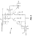
- FIG. 4 is a schematic representation of the automatic gain control circuitry of the embodiment of the present invention illustrated in FIG. 2.
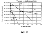
- FIG. 5 is a plot of the vacuum generated versus leakage rate for various conventional systems and the embodiment of the present invention illustrated in FIG. 2.
- FIG. 1 is a representative plot of generated vacuum versus drive voltage for the combination of a preferred nonlinear proportional valve and vacuum pump, the combination used in one embodiment of the present invention, when supplied by a regulated pressure source of about 35154-42184 kg/m 2 (50-60 psi).
- a regulated pressure source of about 35154-42184 kg/m 2 (50-60 psi).
- One suitable nonlinear proportional valve is Model No. 002-AXXAVCAA, available from Porter Instrument Company, Inc., Hatfield, Pennsylvania, although other suitable nonlinear proportional valves may also be used.
- One suitable vacuum pump (venturi) is Model No. LX10, available from PIAB, Hingham, Massachusetts, but other suitable vacuum pumps may also used.
- opening trace 72 indicates that, as the drive voltage increases, the valve opens more quickly (note the steeper slope of opening trace 72 in the range of about 6.5-7.5 volts).
- closing trace 70 decreasing the drive voltage after the valve is fully opened results in the valve closing such that the valve eventually is again fully closed and no vacuum is generated. Closing trace 70 is also nonlinear and moreover does not correspond to opening trace 72.
- valve/venturi combination is evident by the gap 74 between opening trace 72 and closing trace 70.
- the nonlinearity and hysteresis of this valve/venturi combination cannot be adequately compensated for by conventional PID control circuitry such that this valve/venturi can be used to drive ophthalmic surgical instruments.
- FIG. 2 is a block diagram of an embodiment of the pressure control system 1 that is configured to generate vacuum for a suction probe.
- the surgeon chooses the desired vacuum level by manipulating an input device 2, for example, a foot pedal, to generate input signal 4.
- proportional/integral amplifier stage 6 applies gain to the difference between input signal 4 and feedback signal 56, which results in proportional/integral output signal 8.
- Proportional/integral output signal 8 is fed to voltage follower with current boost stage 10 so that drive signal 12 is of sufficient current to open and close proportional valve 18.
- Regulated high pressure source 14 of approximately 35154-42184 kg/m 2 (50-60 psi) is connected via input manifold 16 to proportional valve 18.
- the degree to which proportional valve 18 is open determines the pressure and air flow rate in valve output manifold 20, which connects proportional valve 18 to venturi 22.
- Valve output manifold 20 may alternatively be connected to a surgical device that is driven by positive gage pressure such as a pneumatic scissors (not shown) instead of being connected to venturi 22.
- Vacuum manifold 26 is connected to cassette volume 28 within cassette 30 thus reducing the pressure in cassette volume 28.
- Instrument manifold 40 is also connected to cassette volume 28.
- instrument manifold 40 is connected to surgical instrument 42, such as a suction probe, the surgeon is able to use the suction at the end of the instrument to manipulate material within the patient's eye.
- Debris 32 is material that the surgeon has removed from the patient's eye through instrument 42 and instrument manifold 40 and into cassette 30.
- a constant volume of debris 32 is maintained within cassette 30 by a peristaltic pump (not shown), which pumps excess debris through collection manifold 34 into collection bag 36 for final disposal. The greater the air flow through valve output manifold 20, the lower the pressure in vacuum manifold 26, cassette volume 28, instrument manifold 40, and surgical instrument 42.
- transducer 46 Also connected to vacuum manifold 26 is pressure transducer 46, which generates a transducer signal 48 that varies approximately linearly with the pressure in vacuum manifold 26 (and thus cassette volume 28, instrument manifold 40, and instrument 42). Transducer signal 48 is first fed to transducer amplifier 50, which acts as a buffer and applies gain so that the resulting signal, vacuum signal 52, linearly varies approximately 1 volt for each 13.3 kPa (100 mm Hg) of measured pressure. Vacuum signal 52 is fed to the noninverting input of differential amplifier stage 54.
- differential mode control provides high gain to sharp changes in its input and no gain for steady state input.
- differential amplifier stage 54 provides 0 dB gain (unity gain).
- the gain provided by differential amplifier stage 54 becomes generally constant at approximately 26 dB for frequencies significantly greater than about 14 Hz.
- the resulting feedback signal 56 of differential amplifier stage 54 is compared to input signal 4 by proportional/integral amplifier stage 6 at the start of the feedforward path.
- proportional/integral amplifier stage 6 is set about 10-20 dB higher than a conventional proportional/integral amplifier stage.
- the present invention employs differential amplifier stage 54 in the feedback path (shaded area in FIG. 2), rather than in the feedforward path as in conventional systems.
- differential amplifier stage 54 Because it is in the feedback path, differential amplifier stage 54 only generates high voltage differential output signal 56 in response to actual changes in the process being controlled (i.e., after valve 18 actually responds and vacuum is generated). Differential amplifier stage 54, because its output, feedback signal 56, is connected to the inverting input of proportional/integral amplifier stage 6, operates to temper the gain of proportional/integral amplifier stage 6 when sharp changes in vacuum signal 52 occur.
- proportional/integral amplifier stage 6 When the surgeon makes a sharp change in the input signal 4 (perhaps a step change in the desired pressure level), proportional/integral amplifier stage 6 applies its high gain and attempts to open valve 18 very quickly with a highly boosted drive signal 12. If this sharp change occurs in a region of opening trace 72 of FIG. 1 with a shallow slope, valve 18 does not respond quickly and vacuum does not change as sharply as input signal 4. Differential amplifier stage 54, because it does not receive a sharp change in vacuum signal 52, does not apply gain and does not temper the high gain of proportional/integral amplifier stage 6. Only when valve 18 actually generates vacuum in response to the highly boosted drive signal 12 will differential amplifier stage 54 temper the gain of proportional/integral amplifier stage 6 to reduce drive signal 12.
- differential amplifier stage 54 provides feedback signal 56 that reduces the gain of proportional/integral amplifier stage 6 to a more conventional level.
- the differential stage of a conventional PID control circuit responds to sharp changes in the input signal as well as to the vacuum actually generated because the differential stage is in the feedforward path.
- the PID stage initially, but temporarily, generates a highly boosted drive signal.
- the overall gain provided by the PID circuit may fall off too quickly because the transient error is no longer present to cause the differential stage of the PID to contribute its gain to drive the valve.
- the PID circuit drives the valve based on what now appears to be a steady state error and only the proportional/integral amplifier stages will contribute gain to drive the valve.
- FIG. 3 schematically illustrates simplified versions of the differential amplifier stage 54 and proportional/integral amplifier stage 6.
- Operational amplifier 5, capacitor C2, and resistors R3 and R4 comprise proportional/integral amplifier stage 6.
- Operational amplifier 55, capacitor C1, and resistors R1 and R2 comprise differential amplifier stage 54.
- the gain versus frequency characteristics of proportional/integral amplifier stage 6 and differential amplifier stage 54 are tuned by the combinations of resistors and capacitors chosen according to known methods.
- the circuit as shown in FIG. 3 responds unacceptably slowly to changes in pressure in the range of about 0-6.7 kPa (0-50 mm Hg). To correct for this slow response, automatic gain control circuit (the "AGC”) is incorporated in the circuit of FIG.
- AGC automatic gain control circuit
- circuit 100 uses vacuum signal 52 as an input to vary the resistance value of RC1.
- RC1, RC2, and light emitting diode CR1 are incorporated into a single commercially available LDR package.
- One suitable LDR package is Model No. VTL5C3/2, available from EG&G Vactec Optoeletronics.
- LDR RC1 represents the resistor in FIG. 3 to be varied (R2 or R3).
- the line labeled "FEEDBACK SIGNAL,” which is attached to one terminal of RC1, represents feedback signal 56 of FIGS. 2 and 3, and the opposite terminal of RC1 (shown as an unconnected broken line in FIG. 4) is connected to the appropriate node in FIG.
- a feedback control circuit that is substantially similar to circuit 100 is used to control both R2 and R3, each circuit being tuned to set its respective RC1 to the appropriate value.
- the AGC is comprised of the combination of both circuits (each of which is depicted by circuit 100) that control the resistance value of R2 and R3.
- circuit 100 incorporates RC2 into a control loop to adjust the current supplied to CR1 to compensate for any unit-to-unit variation.
- Operational amplifier A2 generates V1 by applying gain to the difference between vacuum signal 52 (from FIGS. 2 and 3) and VAGC, which is calibrated to be equal to vacuum signal 52 when system 1 is generating 0 kPa (0 mm Hg) vacuum.
- Zener diode 102 determines the maximum value of Vl.
- Current I2 through RC2 is set to a predetermined constant value.
- Current I1 varies proportionally with V1.
- V1 and I1 increase, V2 increases and operational amplifier A1 causes the current through CR1 and thus the light output of CR1 to decrease.
- the reduced light output of CR1 causes the resistance value of RC2 and thus V3 to increase until V3 equals V2.
- decreasing V1 causes the resistance value of RC2 and thus V3 to decrease.
- FIG. 5 is a plot of vacuum generated (at about sea level) versus air leakage rate for the present invention and various conventional systems.
- Trace 60 corresponds to the performance of system 1 (of FIG. 2) and traces 62, 64, and 66 indicate the performance of the prior Storz, Alcon STTO, and Mid-Labs systems respectively.
- Two important pneumatic performance characteristics are apparent from FIG. 5.
- the resistance of a system to air leakage is indicated by the slope of each trace. The more gentle the slope, the greater the resistance of the system to air leakage.
- the resistance of the Storz system is best, the resistance of the Mid-Labs and Alcon STTO systems are worst and the resistance of system 1 is between the extremes.
- FIG. 5 indicates that system 1 is most capable of generating vacuum up to about 80.0 kPa (about 600 mm Hg).
- the Mid-Labs, Alcon STTO, and Storz systems are able to generate about 53.3, 66.7 and 60.0 (projected) kPa (about 400, 500, and 450 (projected) mm Hg).
- system 1 can generate maximum vacuum of 80.0 kPa (600 mm Hg), it is able to provide more vacuum than the Storz system for air leakage rates up to about 130 cc/sec, even though it is not as resistant to air leakage as the Storz system.
- the Storz system consumes about 175 SLPM of air, but system 1 consumes only about 40 SLPM.
- the pneumatic performance of system 1 is possible because its analog control circuitry can adequately compensate for the nonlinearity and hysteresis of the valve/venturi combination of system 1.
Landscapes
- Physics & Mathematics (AREA)
- Engineering & Computer Science (AREA)
- Health & Medical Sciences (AREA)
- Heart & Thoracic Surgery (AREA)
- Fluid Mechanics (AREA)
- Automation & Control Theory (AREA)
- General Physics & Mathematics (AREA)
- Biomedical Technology (AREA)
- Animal Behavior & Ethology (AREA)
- General Health & Medical Sciences (AREA)
- Public Health (AREA)
- Veterinary Medicine (AREA)
- Life Sciences & Earth Sciences (AREA)
- Hematology (AREA)
- Anesthesiology (AREA)
- Vascular Medicine (AREA)
- Feedback Control In General (AREA)
- Control Of Fluid Pressure (AREA)
- Prostheses (AREA)
- Control Of Amplification And Gain Control (AREA)
Claims (8)
- System (1) zum Steuern eines Prozesses, der auf Veränderungen eines Antriebssignals (12) antwortet, umfassend:(a) ein Mittel zum Erzeugen eines gewünschten Prozeßstatussignals (4);(b) eine Proportionalverstärkungsstufe (6), die das Antriebssignal (12) erzeugt, wobei die Proportionalverstärkungsstufe(i) einen invertierenden Eingang und(ii) einen nichtinvertierenden Eingang, mit dem das gewünschte Prozeßstatussignal (4) verbunden ist, umfaßt;(c) einen Prozeßsensor (46), der ein aktuelles Prozeßstatussignal (48) erzeugt, und dadurch gekennzeichnet, daß das System ferner folgendes umfaßt:(d) eine Differenzialverstärkungsstufe (54), verwendend das aktuelle Prozeßstatussignal (48), um ein Rückkopplungssignal zu erzeugen, wobei das Rückkopplungssignal mit dem Invertierungseingang der Proportionalverstärkungsstufe verbunden ist; und daß die Proportionalverstärkungsstufe ferner einen variablen Widerstand (R3) zum Variieren der Verstärkung der Proportionalverstärkungsstufe und ein Mittel zum Variieren des Widerstands des ersten variablen Widerstands innerhalb eines ausgewählten Bereichs an Widerstandswerten umfaßt.
- Steuersystem (1) nach Anspruch 1, dadurch gekennzeichnet, daß die Differenzialverstärkungsstufe (54) ferner einen zweiten variablen Widerstand (R2) zum Variieren der Verstärkung der Differenzialverstärkungsstufe und ein optionelles Mittel zum Variieren des Widerstands des zweiten variablen Widerstands innerhalb eines ausgewählten Bereichs von Widerstandswerten umfaßt.
- Steuersystem (1) nach Anspruch 2, dadurch gekennzeichnet, daß der erste variable Widerstand (R3) und der zweite variable Widerstand (R2) lichtabhängige Widerstände sind, und das Mittel zum Variieren des Widerstands des ersten variablen Widerstands (R3) eine erste lichtemittierende Diode (CR1) umfaßt, die den ersten variablen Widerstand (R3) beleuchtet, und das Mittel zum Variieren des Widerstands des zweiten variablen Widerstands (R2) eine zweite lichtemittierende Diode (CR2) umfaßt, die den zweiten variablen Widerstand (R2) beleuchtet.
- Steuersystem (1) nach irgendeinem der Ansprüche 1 bis 3, zum Steuern eines Prozesses, dadurch gekennzeichnet, daß das Prozeßstatussignal ein Transducersignal (48) ist;der Prozeßsensor ein Drucktransducer (46) ist, und wobei das System ferner folgendes umfaßt:ein pneumatisches System, wobei das pneumatische System folgendes umfaßt:(i) eine regulierte Hochdruckquelle (14)(ii) ein Proportionalventil (18), dessen Position durch das Antriebssignal (12) bestimmt ist; und(iii) einen Ausgabe-Verteiler (20);und die regulierte Hochdruckquelle (14), das Proportionalventil (18) und der Ausgabe-Verteiler (20) jeweils pneumatisch in Reihe in einem pneumatischen System verbunden sind;und der Drucktransducer (46) ein Transducersignal (48) proportional zu dem Druck in dem Ausgabe-Verteiler (20) erzeugt.
- Steuersystem (1) nach Anspruch 4, gekennzeichnet durch ein chirurgisches Instrument, vorzugsweise ein ophtalmisches Instrument, verbunden mit dem Ausgabe-Verteiler (20).
- Steuersystem (1) nach Anspruch 4, gekennzeichnet durch eine Vakuumquelle, vorzugsweise eine Venturi-Vakuumpumpe (22), aufweisend einen Vakuum-Ausgabe-Verteiler (26), wobei der Ausgabe-Verteiler (20) die Vakuumquelle mit dem Proportionalventil (18) verbindet.
- Steuersystem (1) nach Anspruch 6, gekennzeichnet durch ein chirurgisches Instrument, vorzugsweise ein ophtalmisches Instrument, verbunden mit dem Vakuum-Verteiler (26).
- Steuersystem (1) nach irgendeinem der Ansprüche 1 bis 7, gekennzeichnet durch eine Integralverstärkungsstufe, die parallel mit der Proportionalverstärkungsstufe verbunden ist.
Applications Claiming Priority (2)
| Application Number | Priority Date | Filing Date | Title |
|---|---|---|---|
| US548126 | 1983-11-02 | ||
| US08/548,126 US5674194A (en) | 1995-10-25 | 1995-10-25 | Process control system |
Publications (2)
| Publication Number | Publication Date |
|---|---|
| EP0770940A1 EP0770940A1 (de) | 1997-05-02 |
| EP0770940B1 true EP0770940B1 (de) | 1998-04-08 |
Family
ID=24187532
Family Applications (1)
| Application Number | Title | Priority Date | Filing Date |
|---|---|---|---|
| EP96115641A Expired - Lifetime EP0770940B1 (de) | 1995-10-25 | 1996-09-30 | Prozesssteuerungssystem |
Country Status (8)
| Country | Link |
|---|---|
| US (1) | US5674194A (de) |
| EP (1) | EP0770940B1 (de) |
| JP (1) | JP3160539B2 (de) |
| AT (1) | ATE164955T1 (de) |
| AU (1) | AU699515B2 (de) |
| CA (1) | CA2184423C (de) |
| DE (1) | DE69600227T2 (de) |
| ES (1) | ES2115413T3 (de) |
Families Citing this family (47)
| Publication number | Priority date | Publication date | Assignee | Title |
|---|---|---|---|---|
| US5967820A (en) * | 1998-04-07 | 1999-10-19 | Ditto Sales, Inc. | Electrical system for use with ganged furniture |
| US6290690B1 (en) | 1999-06-21 | 2001-09-18 | Alcon Manufacturing, Ltd. | Simultaneous injection and aspiration of viscous fluids in a surgical system |
| US6514268B2 (en) * | 1999-08-30 | 2003-02-04 | Alcon Universal Ltd. | Method of operating microsurgical instruments |
| US6743245B2 (en) | 1999-12-20 | 2004-06-01 | Alcon Universal Ltd. | Asynchronous method of operating microsurgical instruments |
| US7470277B2 (en) * | 2001-10-16 | 2008-12-30 | Alcon, Inc. | Simultaneous proportional control of surgical parameters in a microsurgical system |
| US7232506B2 (en) * | 2003-10-08 | 2007-06-19 | Deposition Sciences, Inc. | System and method for feedforward control in thin film coating processes |
| US7604615B2 (en) * | 2006-03-20 | 2009-10-20 | Alcon, Inc. | Surgical cassette with bubble separating structure |
| US7524299B2 (en) * | 2005-06-21 | 2009-04-28 | Alcon, Inc. | Aspiration control |
| EP1757317A1 (de) * | 2005-08-25 | 2007-02-28 | Ohio Medical Corporation | Kompensierendes Venturivakuumsystem |
| US7600405B2 (en) | 2005-10-11 | 2009-10-13 | Alcon, Inc. | Microsurgical probe |
| US20070185514A1 (en) * | 2006-02-06 | 2007-08-09 | Kirchhevel G L | Microsurgical instrument |
| US8187293B2 (en) * | 2006-02-06 | 2012-05-29 | Novartis Ag | Microsurgical instrument |
| US8465467B2 (en) | 2006-09-14 | 2013-06-18 | Novartis Ag | Method of controlling an irrigation/aspiration system |
| US8679241B2 (en) * | 2006-10-30 | 2014-03-25 | Novartis Ag | Gas pressure monitor for pneumatic surgical machine |
| US8038692B2 (en) | 2006-10-31 | 2011-10-18 | Novartis Ag | Modular design for ophthalmic surgical probe |
| US8162000B2 (en) * | 2006-12-13 | 2012-04-24 | Novartis Ag | Adjustable pneumatic system for a surgical machine |
| US9241830B2 (en) * | 2006-12-15 | 2016-01-26 | Novartis Ag | Pressure monitor for pneumatic vitrectomy machine |
| US8312800B2 (en) * | 2006-12-21 | 2012-11-20 | Novartis Ag | Pneumatic system for a vitrector |
| MX2009005903A (es) * | 2006-12-22 | 2009-06-19 | Alcon Res Ltd | Metodo de operar un instrumento de microcirugia. |
| US20080172078A1 (en) * | 2007-01-16 | 2008-07-17 | Svetic Ralph E | Reduced traction vitrectomy probe |
| US20090018488A1 (en) * | 2007-07-09 | 2009-01-15 | Davis Sherman G | Method of Priming a Surgical System |
| US8080029B2 (en) * | 2007-09-21 | 2011-12-20 | Novartis Ag | System for actuation of a vitreous cutter |
| US9314553B2 (en) * | 2008-01-10 | 2016-04-19 | Alcon Research, Ltd. | Surgical system |
| US20100312169A1 (en) * | 2009-06-03 | 2010-12-09 | Auld Jack R | Method of operating a vitrectomy probe |
| WO2011025658A1 (en) * | 2009-08-31 | 2011-03-03 | Alcon Research, Ltd. | Pneumatic pressure output control by drive valve duty cycle calibration |
| CA2781157C (en) | 2009-12-10 | 2018-01-02 | Alcon Inc. | Systems and methods for dynamic pneumatic valve driver |
| US8666556B2 (en) * | 2009-12-10 | 2014-03-04 | Alcon Research, Ltd. | Systems and methods for dynamic feedforward |
| US8821524B2 (en) | 2010-05-27 | 2014-09-02 | Alcon Research, Ltd. | Feedback control of on/off pneumatic actuators |
| US8298253B2 (en) | 2010-05-27 | 2012-10-30 | Alcon Research, Ltd. | Variable drive vitrectomy cutter |
| US8689439B2 (en) | 2010-08-06 | 2014-04-08 | Abbott Laboratories | Method for forming a tube for use with a pump delivery system |
| US8377001B2 (en) | 2010-10-01 | 2013-02-19 | Abbott Laboratories | Feeding set for a peristaltic pump system |
| US8377000B2 (en) | 2010-10-01 | 2013-02-19 | Abbott Laboratories | Enteral feeding apparatus having a feeding set |
| US9101442B2 (en) | 2010-12-15 | 2015-08-11 | Alcon Research, Ltd. | Reduced friction vitrectomy probe |
| US8808318B2 (en) | 2011-02-28 | 2014-08-19 | Alcon Research, Ltd. | Surgical probe with increased fluid flow |
| US9060841B2 (en) | 2011-08-31 | 2015-06-23 | Alcon Research, Ltd. | Enhanced flow vitrectomy probe |
| US10070990B2 (en) | 2011-12-08 | 2018-09-11 | Alcon Research, Ltd. | Optimized pneumatic drive lines |
| NL2009424C2 (en) | 2012-09-06 | 2014-03-10 | D O R C Dutch Ophthalmic Res Ct International B V | Irrigation/aspiration system, cartridge, pump unit, surgical machine, method for controlling. |
| US9132229B2 (en) | 2012-09-13 | 2015-09-15 | Alcon Research, Ltd. | System and method of priming a surgical cassette |
| US9498378B2 (en) | 2014-04-04 | 2016-11-22 | Novartis Ag | Minimal pulsation ophthalmic probe |
| CN105739307B (zh) * | 2016-01-29 | 2018-08-07 | 浙江大学 | 基于自适应鲁棒控制的比例减压阀滞环补偿装置及方法 |
| WO2018073727A1 (en) | 2016-10-19 | 2018-04-26 | Novartis Ag | Apparatus for controlling vacuum during ocular surgery |
| NL2019884B1 (en) * | 2017-11-10 | 2019-05-17 | Crea Ip B V | Pressure control unit for an ophthalmic surgical system |
| CN110074916B (zh) * | 2019-06-15 | 2024-04-12 | 吉林大学 | 一种高压状态下平衡调节眼部压力装置 |
| JP7625605B2 (ja) * | 2020-01-14 | 2025-02-03 | アルコン インコーポレイティド | ベンチュリ手術システムにおける真空発振防止 |
| US11934209B2 (en) * | 2020-09-14 | 2024-03-19 | Alcon Inc. | Methods and systems for providing control stability in a vacuum generation system using an override proportional-integral-derivative (PID) controller |
| JP7752170B2 (ja) * | 2020-09-14 | 2025-10-09 | アルコン インコーポレイティド | カスケード比例積分微分(pid)コントローラを使用して真空発生システムに制御安定性を提供する方法及びシステム |
| CN115575663B (zh) * | 2022-09-22 | 2025-08-29 | 珠海市迪谱医疗科技有限公司 | 一种气腹机输出气体流速的高精度检测系统及其方法 |
Family Cites Families (14)
| Publication number | Priority date | Publication date | Assignee | Title |
|---|---|---|---|---|
| US4088938A (en) * | 1976-12-17 | 1978-05-09 | Vapor Corporation | Electronic apparatus for positioning and using AC motors |
| US4274411A (en) * | 1979-03-30 | 1981-06-23 | Dotson Robert S Jun | Fluid operated ophthalmic irrigation and aspiration device |
| US4395258A (en) * | 1980-11-03 | 1983-07-26 | Cooper Medical Devices | Linear intra-ocular suction device |
| US4706687A (en) * | 1985-02-28 | 1987-11-17 | Alcon Instrumentation, Inc. | Linear suction control system |
| US4757814A (en) * | 1985-02-28 | 1988-07-19 | Alcon Laboratories, Inc. | Proportional control for pneumatic cutting device |
| US4733149A (en) * | 1985-05-31 | 1988-03-22 | Kollmorgen Technologies Corporation | Adaptive control system |
| US4622503A (en) * | 1985-09-26 | 1986-11-11 | Medical Instrument Development Laboratories, Inc. | Variable pneumatic output means for use with ophthalmic micro-surgical instruments |
| US4770654A (en) * | 1985-09-26 | 1988-09-13 | Alcon Laboratories Inc. | Multimedia apparatus for driving powered surgical instruments |
| US4705067A (en) * | 1986-05-13 | 1987-11-10 | Coffee Curtis L | Electric-to-pressure transducer |
| US5017089A (en) * | 1989-04-11 | 1991-05-21 | United Technologies Corporation | Propeller speed governor having a derivative inhibit at high flight speeds |
| US5094260A (en) * | 1990-10-26 | 1992-03-10 | Alcon Surgical, Inc. | Proportional valve and pressure control system |
| US5097744A (en) * | 1991-01-14 | 1992-03-24 | General Electric Company | Hydraulic control system |
| US5354268A (en) * | 1992-11-04 | 1994-10-11 | Medical Instrument Development Laboratories, Inc. | Methods and apparatus for control of vacuum and pressure for surgical procedures |
| US5380280A (en) * | 1993-11-12 | 1995-01-10 | Peterson; Erik W. | Aspiration system having pressure-controlled and flow-controlled modes |
-
1995
- 1995-10-25 US US08/548,126 patent/US5674194A/en not_active Expired - Lifetime
-
1996
- 1996-08-29 CA CA002184423A patent/CA2184423C/en not_active Expired - Lifetime
- 1996-09-03 AU AU64400/96A patent/AU699515B2/en not_active Expired
- 1996-09-30 EP EP96115641A patent/EP0770940B1/de not_active Expired - Lifetime
- 1996-09-30 DE DE69600227T patent/DE69600227T2/de not_active Expired - Lifetime
- 1996-09-30 ES ES96115641T patent/ES2115413T3/es not_active Expired - Lifetime
- 1996-09-30 AT AT96115641T patent/ATE164955T1/de not_active IP Right Cessation
- 1996-10-18 JP JP27618896A patent/JP3160539B2/ja not_active Expired - Lifetime
Also Published As
| Publication number | Publication date |
|---|---|
| AU699515B2 (en) | 1998-12-03 |
| ES2115413T3 (es) | 1998-06-16 |
| CA2184423A1 (en) | 1997-04-26 |
| CA2184423C (en) | 2003-03-18 |
| AU6440096A (en) | 1997-05-01 |
| EP0770940A1 (de) | 1997-05-02 |
| DE69600227T2 (de) | 1998-09-10 |
| JPH09171401A (ja) | 1997-06-30 |
| JP3160539B2 (ja) | 2001-04-25 |
| ATE164955T1 (de) | 1998-04-15 |
| DE69600227D1 (de) | 1998-05-14 |
| US5674194A (en) | 1997-10-07 |
Similar Documents
| Publication | Publication Date | Title |
|---|---|---|
| CA2184423C (en) | Process control system | |
| US5520652A (en) | Methods and apparatus for control of vacuum and pressure for surgical procedures | |
| AU727779B2 (en) | Control system for a phacoemulsification handpiece | |
| US5549546A (en) | Insufflation device | |
| AU719577B2 (en) | System and method for tuning and controlling an ultrasonic handpiece | |
| US4966578A (en) | Apparatus for the insufflation of gas into a body cavity | |
| JPH0653175B2 (ja) | 流動媒体の流量調節装置およびベンチレータ | |
| JPH0231408B2 (de) | ||
| IL104682A (en) | Aspiration control system | |
| CA2038797C (en) | Controller | |
| JPS6318414A (ja) | 真空室の圧力調整、制御装置および方法 | |
| EP0294072B2 (de) | Vorrichtung zum Steuern oder Regeln des Durchflusses eines Druckgases zwischen zwei Druckgasvorrichtungen | |
| US5033496A (en) | Current to pressure transducer | |
| EP0435612A2 (de) | Spannungsfolger eingesetzt in Leistungssteuerungsschaltungen | |
| KR890000611B1 (ko) | 전자-공기식 변환기용 제어 시스템 | |
| EP0775339B1 (de) | Strom/druck-wandler mit selektierbarem, einstellbarem eingangsfilter | |
| CH635465A5 (it) | Procedimento e circuito di pilotaggio di un dispositivo elettronico non lineare a soglia. | |
| US5103084A (en) | Adjustable radiation-controlled filter with voltage controlled bandwidth | |
| US5629570A (en) | Paint flow control interface | |
| US20230414133A1 (en) | Air-pump arrangement for an acoustic measurement device | |
| JPH0211884B2 (de) | ||
| KR100214571B1 (ko) | 영상기기의 알에프 자동이득 제어부 조정장치 | |
| US5162646A (en) | Radiation-controlled filter with photoconductor means and feedback thereto | |
| KR0140582B1 (ko) | 기압계 교정자동화 시스템 | |
| JPS6358224A (ja) | 試験用圧力発生器 |
Legal Events
| Date | Code | Title | Description |
|---|---|---|---|
| PUAI | Public reference made under article 153(3) epc to a published international application that has entered the european phase |
Free format text: ORIGINAL CODE: 0009012 |
|
| 17P | Request for examination filed |
Effective date: 19960930 |
|
| AK | Designated contracting states |
Kind code of ref document: A1 Designated state(s): AT BE CH DE DK ES FI FR GB GR IE IT LI LU MC NL PT SE |
|
| GRAG | Despatch of communication of intention to grant |
Free format text: ORIGINAL CODE: EPIDOS AGRA |
|
| GRAG | Despatch of communication of intention to grant |
Free format text: ORIGINAL CODE: EPIDOS AGRA |
|
| GRAH | Despatch of communication of intention to grant a patent |
Free format text: ORIGINAL CODE: EPIDOS IGRA |
|
| GRAG | Despatch of communication of intention to grant |
Free format text: ORIGINAL CODE: EPIDOS AGRA |
|
| GRAG | Despatch of communication of intention to grant |
Free format text: ORIGINAL CODE: EPIDOS AGRA |
|
| GRAH | Despatch of communication of intention to grant a patent |
Free format text: ORIGINAL CODE: EPIDOS IGRA |
|
| GRAH | Despatch of communication of intention to grant a patent |
Free format text: ORIGINAL CODE: EPIDOS IGRA |
|
| GRAA | (expected) grant |
Free format text: ORIGINAL CODE: 0009210 |
|
| AK | Designated contracting states |
Kind code of ref document: B1 Designated state(s): AT BE CH DE DK ES FI FR GB GR IE IT LI LU MC NL PT SE |
|
| PG25 | Lapsed in a contracting state [announced via postgrant information from national office to epo] |
Ref country code: GR Free format text: LAPSE BECAUSE OF FAILURE TO SUBMIT A TRANSLATION OF THE DESCRIPTION OR TO PAY THE FEE WITHIN THE PRESCRIBED TIME-LIMIT Effective date: 19980408 Ref country code: FI Free format text: LAPSE BECAUSE OF NON-PAYMENT OF DUE FEES Effective date: 19980408 Ref country code: BE Free format text: LAPSE BECAUSE OF FAILURE TO SUBMIT A TRANSLATION OF THE DESCRIPTION OR TO PAY THE FEE WITHIN THE PRESCRIBED TIME-LIMIT Effective date: 19980408 Ref country code: AT Free format text: LAPSE BECAUSE OF FAILURE TO SUBMIT A TRANSLATION OF THE DESCRIPTION OR TO PAY THE FEE WITHIN THE PRESCRIBED TIME-LIMIT Effective date: 19980408 |
|
| REF | Corresponds to: |
Ref document number: 164955 Country of ref document: AT Date of ref document: 19980415 Kind code of ref document: T |
|
| ITF | It: translation for a ep patent filed | ||
| REG | Reference to a national code |
Ref country code: CH Ref legal event code: EP |
|
| REF | Corresponds to: |
Ref document number: 69600227 Country of ref document: DE Date of ref document: 19980514 |
|
| ET | Fr: translation filed | ||
| REG | Reference to a national code |
Ref country code: ES Ref legal event code: FG2A Ref document number: 2115413 Country of ref document: ES Kind code of ref document: T3 |
|
| REG | Reference to a national code |
Ref country code: CH Ref legal event code: NV Representative=s name: PATENTANWALTSBUERO ZINK |
|
| PG25 | Lapsed in a contracting state [announced via postgrant information from national office to epo] |
Ref country code: SE Free format text: LAPSE BECAUSE OF FAILURE TO SUBMIT A TRANSLATION OF THE DESCRIPTION OR TO PAY THE FEE WITHIN THE PRESCRIBED TIME-LIMIT Effective date: 19980708 Ref country code: PT Free format text: LAPSE BECAUSE OF FAILURE TO SUBMIT A TRANSLATION OF THE DESCRIPTION OR TO PAY THE FEE WITHIN THE PRESCRIBED TIME-LIMIT Effective date: 19980708 Ref country code: DK Free format text: LAPSE BECAUSE OF FAILURE TO SUBMIT A TRANSLATION OF THE DESCRIPTION OR TO PAY THE FEE WITHIN THE PRESCRIBED TIME-LIMIT Effective date: 19980708 |
|
| REG | Reference to a national code |
Ref country code: IE Ref legal event code: FG4D Free format text: 79778 |
|
| PG25 | Lapsed in a contracting state [announced via postgrant information from national office to epo] |
Ref country code: LU Free format text: LAPSE BECAUSE OF NON-PAYMENT OF DUE FEES Effective date: 19980930 Ref country code: IE Free format text: LAPSE BECAUSE OF NON-PAYMENT OF DUE FEES Effective date: 19980930 |
|
| PLBE | No opposition filed within time limit |
Free format text: ORIGINAL CODE: 0009261 |
|
| STAA | Information on the status of an ep patent application or granted ep patent |
Free format text: STATUS: NO OPPOSITION FILED WITHIN TIME LIMIT |
|
| 26N | No opposition filed | ||
| PG25 | Lapsed in a contracting state [announced via postgrant information from national office to epo] |
Ref country code: MC Free format text: LAPSE BECAUSE OF NON-PAYMENT OF DUE FEES Effective date: 19990331 |
|
| REG | Reference to a national code |
Ref country code: GB Ref legal event code: IF02 |
|
| REG | Reference to a national code |
Ref country code: FR Ref legal event code: PLFP Year of fee payment: 20 |
|
| PGFP | Annual fee paid to national office [announced via postgrant information from national office to epo] |
Ref country code: DE Payment date: 20150922 Year of fee payment: 20 Ref country code: CH Payment date: 20150911 Year of fee payment: 20 Ref country code: GB Payment date: 20150930 Year of fee payment: 20 Ref country code: ES Payment date: 20150810 Year of fee payment: 20 |
|
| PGFP | Annual fee paid to national office [announced via postgrant information from national office to epo] |
Ref country code: FR Payment date: 20150629 Year of fee payment: 20 |
|
| PGFP | Annual fee paid to national office [announced via postgrant information from national office to epo] |
Ref country code: IT Payment date: 20150925 Year of fee payment: 20 |
|
| PGFP | Annual fee paid to national office [announced via postgrant information from national office to epo] |
Ref country code: NL Payment date: 20150909 Year of fee payment: 20 |
|
| REG | Reference to a national code |
Ref country code: DE Ref legal event code: R071 Ref document number: 69600227 Country of ref document: DE |
|
| REG | Reference to a national code |
Ref country code: NL Ref legal event code: MK Effective date: 20160929 |
|
| REG | Reference to a national code |
Ref country code: CH Ref legal event code: PL |
|
| REG | Reference to a national code |
Ref country code: GB Ref legal event code: PE20 Expiry date: 20160929 |
|
| PG25 | Lapsed in a contracting state [announced via postgrant information from national office to epo] |
Ref country code: GB Free format text: LAPSE BECAUSE OF EXPIRATION OF PROTECTION Effective date: 20160929 |
|
| REG | Reference to a national code |
Ref country code: ES Ref legal event code: FD2A Effective date: 20170126 |
|
| PG25 | Lapsed in a contracting state [announced via postgrant information from national office to epo] |
Ref country code: ES Free format text: LAPSE BECAUSE OF EXPIRATION OF PROTECTION Effective date: 20161001 |