EP0770816B1 - Apparatus for storing a multi-component cryogenic liquid - Google Patents
Apparatus for storing a multi-component cryogenic liquid Download PDFInfo
- Publication number
- EP0770816B1 EP0770816B1 EP96307641A EP96307641A EP0770816B1 EP 0770816 B1 EP0770816 B1 EP 0770816B1 EP 96307641 A EP96307641 A EP 96307641A EP 96307641 A EP96307641 A EP 96307641A EP 0770816 B1 EP0770816 B1 EP 0770816B1
- Authority
- EP
- European Patent Office
- Prior art keywords
- headspace
- pressure
- storage tank
- vapour
- tank
- Prior art date
- Legal status (The legal status is an assumption and is not a legal conclusion. Google has not performed a legal analysis and makes no representation as to the accuracy of the status listed.)
- Expired - Lifetime
Links
- 239000007788 liquid Substances 0.000 title claims description 34
- 238000009833 condensation Methods 0.000 claims description 17
- 230000005494 condensation Effects 0.000 claims description 17
- 238000013022 venting Methods 0.000 claims description 6
- 238000004891 communication Methods 0.000 claims description 2
- IJGRMHOSHXDMSA-UHFFFAOYSA-N Atomic nitrogen Chemical compound N#N IJGRMHOSHXDMSA-UHFFFAOYSA-N 0.000 description 2
- 239000007789 gas Substances 0.000 description 2
- 239000000203 mixture Substances 0.000 description 2
- 238000013459 approach Methods 0.000 description 1
- QVGXLLKOCUKJST-UHFFFAOYSA-N atomic oxygen Chemical compound [O] QVGXLLKOCUKJST-UHFFFAOYSA-N 0.000 description 1
- 238000011217 control strategy Methods 0.000 description 1
- -1 for instance Substances 0.000 description 1
- 238000004519 manufacturing process Methods 0.000 description 1
- 238000000034 method Methods 0.000 description 1
- 229910052757 nitrogen Inorganic materials 0.000 description 1
- 239000001301 oxygen Substances 0.000 description 1
- 229910052760 oxygen Inorganic materials 0.000 description 1
- 238000009428 plumbing Methods 0.000 description 1
- 238000005086 pumping Methods 0.000 description 1
- 230000001105 regulatory effect Effects 0.000 description 1
- 238000009420 retrofitting Methods 0.000 description 1
- 238000012546 transfer Methods 0.000 description 1
- 238000009834 vaporization Methods 0.000 description 1
Images
Classifications
-
- F—MECHANICAL ENGINEERING; LIGHTING; HEATING; WEAPONS; BLASTING
- F17—STORING OR DISTRIBUTING GASES OR LIQUIDS
- F17C—VESSELS FOR CONTAINING OR STORING COMPRESSED, LIQUEFIED OR SOLIDIFIED GASES; FIXED-CAPACITY GAS-HOLDERS; FILLING VESSELS WITH, OR DISCHARGING FROM VESSELS, COMPRESSED, LIQUEFIED, OR SOLIDIFIED GASES
- F17C9/00—Methods or apparatus for discharging liquefied or solidified gases from vessels not under pressure
- F17C9/02—Methods or apparatus for discharging liquefied or solidified gases from vessels not under pressure with change of state, e.g. vaporisation
-
- F—MECHANICAL ENGINEERING; LIGHTING; HEATING; WEAPONS; BLASTING
- F17—STORING OR DISTRIBUTING GASES OR LIQUIDS
- F17C—VESSELS FOR CONTAINING OR STORING COMPRESSED, LIQUEFIED OR SOLIDIFIED GASES; FIXED-CAPACITY GAS-HOLDERS; FILLING VESSELS WITH, OR DISCHARGING FROM VESSELS, COMPRESSED, LIQUEFIED, OR SOLIDIFIED GASES
- F17C13/00—Details of vessels or of the filling or discharging of vessels
- F17C13/02—Special adaptations of indicating, measuring, or monitoring equipment
- F17C13/025—Special adaptations of indicating, measuring, or monitoring equipment having the pressure as the parameter
-
- F—MECHANICAL ENGINEERING; LIGHTING; HEATING; WEAPONS; BLASTING
- F25—REFRIGERATION OR COOLING; COMBINED HEATING AND REFRIGERATION SYSTEMS; HEAT PUMP SYSTEMS; MANUFACTURE OR STORAGE OF ICE; LIQUEFACTION SOLIDIFICATION OF GASES
- F25J—LIQUEFACTION, SOLIDIFICATION OR SEPARATION OF GASES OR GASEOUS OR LIQUEFIED GASEOUS MIXTURES BY PRESSURE AND COLD TREATMENT OR BY BRINGING THEM INTO THE SUPERCRITICAL STATE
- F25J1/00—Processes or apparatus for liquefying or solidifying gases or gaseous mixtures
- F25J1/0002—Processes or apparatus for liquefying or solidifying gases or gaseous mixtures characterised by the fluid to be liquefied
- F25J1/0012—Primary atmospheric gases, e.g. air
-
- F—MECHANICAL ENGINEERING; LIGHTING; HEATING; WEAPONS; BLASTING
- F25—REFRIGERATION OR COOLING; COMBINED HEATING AND REFRIGERATION SYSTEMS; HEAT PUMP SYSTEMS; MANUFACTURE OR STORAGE OF ICE; LIQUEFACTION SOLIDIFICATION OF GASES
- F25J—LIQUEFACTION, SOLIDIFICATION OR SEPARATION OF GASES OR GASEOUS OR LIQUEFIED GASEOUS MIXTURES BY PRESSURE AND COLD TREATMENT OR BY BRINGING THEM INTO THE SUPERCRITICAL STATE
- F25J1/00—Processes or apparatus for liquefying or solidifying gases or gaseous mixtures
- F25J1/003—Processes or apparatus for liquefying or solidifying gases or gaseous mixtures characterised by the kind of cold generation within the liquefaction unit for compensating heat leaks and liquid production
- F25J1/0032—Processes or apparatus for liquefying or solidifying gases or gaseous mixtures characterised by the kind of cold generation within the liquefaction unit for compensating heat leaks and liquid production using the feed stream itself or separated fractions from it, i.e. "internal refrigeration"
- F25J1/0045—Processes or apparatus for liquefying or solidifying gases or gaseous mixtures characterised by the kind of cold generation within the liquefaction unit for compensating heat leaks and liquid production using the feed stream itself or separated fractions from it, i.e. "internal refrigeration" by vaporising a liquid return stream
-
- F—MECHANICAL ENGINEERING; LIGHTING; HEATING; WEAPONS; BLASTING
- F25—REFRIGERATION OR COOLING; COMBINED HEATING AND REFRIGERATION SYSTEMS; HEAT PUMP SYSTEMS; MANUFACTURE OR STORAGE OF ICE; LIQUEFACTION SOLIDIFICATION OF GASES
- F25J—LIQUEFACTION, SOLIDIFICATION OR SEPARATION OF GASES OR GASEOUS OR LIQUEFIED GASEOUS MIXTURES BY PRESSURE AND COLD TREATMENT OR BY BRINGING THEM INTO THE SUPERCRITICAL STATE
- F25J1/00—Processes or apparatus for liquefying or solidifying gases or gaseous mixtures
- F25J1/02—Processes or apparatus for liquefying or solidifying gases or gaseous mixtures requiring the use of refrigeration, e.g. of helium or hydrogen ; Details and kind of the refrigeration system used; Integration with other units or processes; Controlling aspects of the process
- F25J1/0221—Processes or apparatus for liquefying or solidifying gases or gaseous mixtures requiring the use of refrigeration, e.g. of helium or hydrogen ; Details and kind of the refrigeration system used; Integration with other units or processes; Controlling aspects of the process using the cold stored in an external cryogenic component in an open refrigeration loop
-
- F—MECHANICAL ENGINEERING; LIGHTING; HEATING; WEAPONS; BLASTING
- F25—REFRIGERATION OR COOLING; COMBINED HEATING AND REFRIGERATION SYSTEMS; HEAT PUMP SYSTEMS; MANUFACTURE OR STORAGE OF ICE; LIQUEFACTION SOLIDIFICATION OF GASES
- F25J—LIQUEFACTION, SOLIDIFICATION OR SEPARATION OF GASES OR GASEOUS OR LIQUEFIED GASEOUS MIXTURES BY PRESSURE AND COLD TREATMENT OR BY BRINGING THEM INTO THE SUPERCRITICAL STATE
- F25J1/00—Processes or apparatus for liquefying or solidifying gases or gaseous mixtures
- F25J1/02—Processes or apparatus for liquefying or solidifying gases or gaseous mixtures requiring the use of refrigeration, e.g. of helium or hydrogen ; Details and kind of the refrigeration system used; Integration with other units or processes; Controlling aspects of the process
- F25J1/0243—Start-up or control of the process; Details of the apparatus used; Details of the refrigerant compression system used
- F25J1/0257—Construction and layout of liquefaction equipments, e.g. valves, machines
- F25J1/0274—Retrofitting or revamping of an existing liquefaction unit
-
- F—MECHANICAL ENGINEERING; LIGHTING; HEATING; WEAPONS; BLASTING
- F17—STORING OR DISTRIBUTING GASES OR LIQUIDS
- F17C—VESSELS FOR CONTAINING OR STORING COMPRESSED, LIQUEFIED OR SOLIDIFIED GASES; FIXED-CAPACITY GAS-HOLDERS; FILLING VESSELS WITH, OR DISCHARGING FROM VESSELS, COMPRESSED, LIQUEFIED, OR SOLIDIFIED GASES
- F17C2205/00—Vessel construction, in particular mounting arrangements, attachments or identifications means
- F17C2205/01—Mounting arrangements
- F17C2205/0153—Details of mounting arrangements
- F17C2205/0176—Details of mounting arrangements with ventilation
-
- F—MECHANICAL ENGINEERING; LIGHTING; HEATING; WEAPONS; BLASTING
- F17—STORING OR DISTRIBUTING GASES OR LIQUIDS
- F17C—VESSELS FOR CONTAINING OR STORING COMPRESSED, LIQUEFIED OR SOLIDIFIED GASES; FIXED-CAPACITY GAS-HOLDERS; FILLING VESSELS WITH, OR DISCHARGING FROM VESSELS, COMPRESSED, LIQUEFIED, OR SOLIDIFIED GASES
- F17C2205/00—Vessel construction, in particular mounting arrangements, attachments or identifications means
- F17C2205/03—Fluid connections, filters, valves, closure means or other attachments
- F17C2205/0302—Fittings, valves, filters, or components in connection with the gas storage device
- F17C2205/0323—Valves
- F17C2205/0326—Valves electrically actuated
-
- F—MECHANICAL ENGINEERING; LIGHTING; HEATING; WEAPONS; BLASTING
- F17—STORING OR DISTRIBUTING GASES OR LIQUIDS
- F17C—VESSELS FOR CONTAINING OR STORING COMPRESSED, LIQUEFIED OR SOLIDIFIED GASES; FIXED-CAPACITY GAS-HOLDERS; FILLING VESSELS WITH, OR DISCHARGING FROM VESSELS, COMPRESSED, LIQUEFIED, OR SOLIDIFIED GASES
- F17C2205/00—Vessel construction, in particular mounting arrangements, attachments or identifications means
- F17C2205/03—Fluid connections, filters, valves, closure means or other attachments
- F17C2205/0302—Fittings, valves, filters, or components in connection with the gas storage device
- F17C2205/0323—Valves
- F17C2205/0335—Check-valves or non-return valves
-
- F—MECHANICAL ENGINEERING; LIGHTING; HEATING; WEAPONS; BLASTING
- F17—STORING OR DISTRIBUTING GASES OR LIQUIDS
- F17C—VESSELS FOR CONTAINING OR STORING COMPRESSED, LIQUEFIED OR SOLIDIFIED GASES; FIXED-CAPACITY GAS-HOLDERS; FILLING VESSELS WITH, OR DISCHARGING FROM VESSELS, COMPRESSED, LIQUEFIED, OR SOLIDIFIED GASES
- F17C2221/00—Handled fluid, in particular type of fluid
- F17C2221/03—Mixtures
- F17C2221/031—Air
-
- F—MECHANICAL ENGINEERING; LIGHTING; HEATING; WEAPONS; BLASTING
- F17—STORING OR DISTRIBUTING GASES OR LIQUIDS
- F17C—VESSELS FOR CONTAINING OR STORING COMPRESSED, LIQUEFIED OR SOLIDIFIED GASES; FIXED-CAPACITY GAS-HOLDERS; FILLING VESSELS WITH, OR DISCHARGING FROM VESSELS, COMPRESSED, LIQUEFIED, OR SOLIDIFIED GASES
- F17C2223/00—Handled fluid before transfer, i.e. state of fluid when stored in the vessel or before transfer from the vessel
- F17C2223/01—Handled fluid before transfer, i.e. state of fluid when stored in the vessel or before transfer from the vessel characterised by the phase
- F17C2223/0146—Two-phase
- F17C2223/0153—Liquefied gas, e.g. LPG, GPL
- F17C2223/0161—Liquefied gas, e.g. LPG, GPL cryogenic, e.g. LNG, GNL, PLNG
-
- F—MECHANICAL ENGINEERING; LIGHTING; HEATING; WEAPONS; BLASTING
- F17—STORING OR DISTRIBUTING GASES OR LIQUIDS
- F17C—VESSELS FOR CONTAINING OR STORING COMPRESSED, LIQUEFIED OR SOLIDIFIED GASES; FIXED-CAPACITY GAS-HOLDERS; FILLING VESSELS WITH, OR DISCHARGING FROM VESSELS, COMPRESSED, LIQUEFIED, OR SOLIDIFIED GASES
- F17C2225/00—Handled fluid after transfer, i.e. state of fluid after transfer from the vessel
- F17C2225/01—Handled fluid after transfer, i.e. state of fluid after transfer from the vessel characterised by the phase
- F17C2225/0146—Two-phase
- F17C2225/0153—Liquefied gas, e.g. LPG, GPL
- F17C2225/0161—Liquefied gas, e.g. LPG, GPL cryogenic, e.g. LNG, GNL, PLNG
-
- F—MECHANICAL ENGINEERING; LIGHTING; HEATING; WEAPONS; BLASTING
- F17—STORING OR DISTRIBUTING GASES OR LIQUIDS
- F17C—VESSELS FOR CONTAINING OR STORING COMPRESSED, LIQUEFIED OR SOLIDIFIED GASES; FIXED-CAPACITY GAS-HOLDERS; FILLING VESSELS WITH, OR DISCHARGING FROM VESSELS, COMPRESSED, LIQUEFIED, OR SOLIDIFIED GASES
- F17C2225/00—Handled fluid after transfer, i.e. state of fluid after transfer from the vessel
- F17C2225/03—Handled fluid after transfer, i.e. state of fluid after transfer from the vessel characterised by the pressure level
- F17C2225/033—Small pressure, e.g. for liquefied gas
-
- F—MECHANICAL ENGINEERING; LIGHTING; HEATING; WEAPONS; BLASTING
- F17—STORING OR DISTRIBUTING GASES OR LIQUIDS
- F17C—VESSELS FOR CONTAINING OR STORING COMPRESSED, LIQUEFIED OR SOLIDIFIED GASES; FIXED-CAPACITY GAS-HOLDERS; FILLING VESSELS WITH, OR DISCHARGING FROM VESSELS, COMPRESSED, LIQUEFIED, OR SOLIDIFIED GASES
- F17C2227/00—Transfer of fluids, i.e. method or means for transferring the fluid; Heat exchange with the fluid
- F17C2227/03—Heat exchange with the fluid
- F17C2227/0302—Heat exchange with the fluid by heating
- F17C2227/0304—Heat exchange with the fluid by heating using an electric heater
-
- F—MECHANICAL ENGINEERING; LIGHTING; HEATING; WEAPONS; BLASTING
- F17—STORING OR DISTRIBUTING GASES OR LIQUIDS
- F17C—VESSELS FOR CONTAINING OR STORING COMPRESSED, LIQUEFIED OR SOLIDIFIED GASES; FIXED-CAPACITY GAS-HOLDERS; FILLING VESSELS WITH, OR DISCHARGING FROM VESSELS, COMPRESSED, LIQUEFIED, OR SOLIDIFIED GASES
- F17C2227/00—Transfer of fluids, i.e. method or means for transferring the fluid; Heat exchange with the fluid
- F17C2227/03—Heat exchange with the fluid
- F17C2227/0367—Localisation of heat exchange
- F17C2227/0388—Localisation of heat exchange separate
- F17C2227/0393—Localisation of heat exchange separate using a vaporiser
-
- F—MECHANICAL ENGINEERING; LIGHTING; HEATING; WEAPONS; BLASTING
- F17—STORING OR DISTRIBUTING GASES OR LIQUIDS
- F17C—VESSELS FOR CONTAINING OR STORING COMPRESSED, LIQUEFIED OR SOLIDIFIED GASES; FIXED-CAPACITY GAS-HOLDERS; FILLING VESSELS WITH, OR DISCHARGING FROM VESSELS, COMPRESSED, LIQUEFIED, OR SOLIDIFIED GASES
- F17C2250/00—Accessories; Control means; Indicating, measuring or monitoring of parameters
- F17C2250/01—Intermediate tanks
-
- F—MECHANICAL ENGINEERING; LIGHTING; HEATING; WEAPONS; BLASTING
- F17—STORING OR DISTRIBUTING GASES OR LIQUIDS
- F17C—VESSELS FOR CONTAINING OR STORING COMPRESSED, LIQUEFIED OR SOLIDIFIED GASES; FIXED-CAPACITY GAS-HOLDERS; FILLING VESSELS WITH, OR DISCHARGING FROM VESSELS, COMPRESSED, LIQUEFIED, OR SOLIDIFIED GASES
- F17C2250/00—Accessories; Control means; Indicating, measuring or monitoring of parameters
- F17C2250/04—Indicating or measuring of parameters as input values
- F17C2250/0404—Parameters indicated or measured
- F17C2250/043—Pressure
-
- F—MECHANICAL ENGINEERING; LIGHTING; HEATING; WEAPONS; BLASTING
- F17—STORING OR DISTRIBUTING GASES OR LIQUIDS
- F17C—VESSELS FOR CONTAINING OR STORING COMPRESSED, LIQUEFIED OR SOLIDIFIED GASES; FIXED-CAPACITY GAS-HOLDERS; FILLING VESSELS WITH, OR DISCHARGING FROM VESSELS, COMPRESSED, LIQUEFIED, OR SOLIDIFIED GASES
- F17C2250/00—Accessories; Control means; Indicating, measuring or monitoring of parameters
- F17C2250/06—Controlling or regulating of parameters as output values
- F17C2250/0605—Parameters
- F17C2250/0626—Pressure
-
- F—MECHANICAL ENGINEERING; LIGHTING; HEATING; WEAPONS; BLASTING
- F25—REFRIGERATION OR COOLING; COMBINED HEATING AND REFRIGERATION SYSTEMS; HEAT PUMP SYSTEMS; MANUFACTURE OR STORAGE OF ICE; LIQUEFACTION SOLIDIFICATION OF GASES
- F25J—LIQUEFACTION, SOLIDIFICATION OR SEPARATION OF GASES OR GASEOUS OR LIQUEFIED GASEOUS MIXTURES BY PRESSURE AND COLD TREATMENT OR BY BRINGING THEM INTO THE SUPERCRITICAL STATE
- F25J2210/00—Processes characterised by the type or other details of the feed stream
- F25J2210/40—Air or oxygen enriched air, i.e. generally less than 30mol% of O2
-
- F—MECHANICAL ENGINEERING; LIGHTING; HEATING; WEAPONS; BLASTING
- F25—REFRIGERATION OR COOLING; COMBINED HEATING AND REFRIGERATION SYSTEMS; HEAT PUMP SYSTEMS; MANUFACTURE OR STORAGE OF ICE; LIQUEFACTION SOLIDIFICATION OF GASES
- F25J—LIQUEFACTION, SOLIDIFICATION OR SEPARATION OF GASES OR GASEOUS OR LIQUEFIED GASEOUS MIXTURES BY PRESSURE AND COLD TREATMENT OR BY BRINGING THEM INTO THE SUPERCRITICAL STATE
- F25J2210/00—Processes characterised by the type or other details of the feed stream
- F25J2210/90—Boil-off gas from storage
-
- F—MECHANICAL ENGINEERING; LIGHTING; HEATING; WEAPONS; BLASTING
- F25—REFRIGERATION OR COOLING; COMBINED HEATING AND REFRIGERATION SYSTEMS; HEAT PUMP SYSTEMS; MANUFACTURE OR STORAGE OF ICE; LIQUEFACTION SOLIDIFICATION OF GASES
- F25J—LIQUEFACTION, SOLIDIFICATION OR SEPARATION OF GASES OR GASEOUS OR LIQUEFIED GASEOUS MIXTURES BY PRESSURE AND COLD TREATMENT OR BY BRINGING THEM INTO THE SUPERCRITICAL STATE
- F25J2280/00—Control of the process or apparatus
- F25J2280/02—Control in general, load changes, different modes ("runs"), measurements
-
- F—MECHANICAL ENGINEERING; LIGHTING; HEATING; WEAPONS; BLASTING
- F25—REFRIGERATION OR COOLING; COMBINED HEATING AND REFRIGERATION SYSTEMS; HEAT PUMP SYSTEMS; MANUFACTURE OR STORAGE OF ICE; LIQUEFACTION SOLIDIFICATION OF GASES
- F25J—LIQUEFACTION, SOLIDIFICATION OR SEPARATION OF GASES OR GASEOUS OR LIQUEFIED GASEOUS MIXTURES BY PRESSURE AND COLD TREATMENT OR BY BRINGING THEM INTO THE SUPERCRITICAL STATE
- F25J2290/00—Other details not covered by groups F25J2200/00 - F25J2280/00
- F25J2290/62—Details of storing a fluid in a tank
Definitions
- the present invention relates to an apparatus for storing a multi-component cryogenic liquid within a storage tank. More particularly, the present invention relates to such an apparatus in which headspace vapour within the storage tank is condensed by indirect heat transfer with the cryogenic liquid. More particularly, the present invention relates to such an apparatus in which the headspace vapour is condensed within an external condensation tank and the resulting condensate is returned to the storage vessel by a pressure building circuit.
- Cryogenic storage vessels and dewars are used to store cryogenic liquids, for instance, liquefied atmospheric gases, either at their point of use or for use in the transport of such cryogenic liquids.
- cryogenic liquids for instance, liquefied atmospheric gases
- Such storage tanks and dewars are insulated, there is still heat leakage into the storage tank or dewar. This heat leakage causes vaporisation of the liquid cryogen.
- the vapour is vented from a headspace region of the tank to prevent overpressurisation of the tank.
- the liquid cryogen is a multi-component mixture, for instance air
- the venting of the vapour phase presents a problem because the more volatile components will vaporise before the less volatile components.
- the liquid being stored will have an ever increasing concentration of the less volatile components. For instance, if the liquid cryogen being stored is liquid air, nitrogen (as well as other components of the air but at a lower concentration) will be vented to cause the liquid to have an ever increasing oxygen content.
- US-A-3,260,060 discloses a cryogenic dewar in which liquid is vented through a heat exchanger located within the headspace region of the dewar. As pressure within the dewar increases, the liquid passing through the heat exchanger condenses the vapour to stabilise the concentration of the liquid. Since the liquid, now vaporised, is at the same concentration of the bulk liquid, there is no concentration change.
- cryogenic dewar illustrated in US-A-3,260,060 involves manufacturing dewars with heat exchangers in the headspace region and thus, cannot easily serve as a retrofit to existing cryogenic dewars.
- the present invention solves the retrofitting problem by providing a cryogenic storage apparatus that is easily adapted as a retrofit for conventional cryogenic storage tanks and dewars.
- an apparatus for storing a multi-component cryogenic liquid comprising, a storage tank for said multi-component cryogenic liquid; a condensation tank located external to said storage tank for condensing headspace vapour; heat exchange means located within said condensation tank for condensing said headspace vapour, said heat exchange means in communication with said storage tank and venting to atmosphere so that a liquid stream from said storage tank is able, in use, to vaporise within said heat exchange means in indirect heat exchange with condensing headspace vapour and vent to atmosphere; first actuable valve means for permitting said liquid stream to flow to said heat exchange means when pressure within said headspace region is above a predetermined value; said condensation tank having an inlet communicating with the headspace of the storage tank and an outlet communicating with the storage tank; and means for driving said condensed headspace vapour back into said storage tank after said pressure falls below said predetermined value.
- multi-component means having two or more components.
- an apparatus 1 in accordance with the present invention is provided for storing a multi-component cryogenic liquid, for instance, liquid air.
- Apparatus 1 utilises a conventional storage tank 10 containing a multi-component liquid cryogen 12.
- Storage tank 10 is thermally insulated in a conventional manner. Nonetheless, there is still some "heat inleakage" into the tank 10. Due to this heat leakage into the tank 10, liquid cryogen 12 vaporises to form vapour within a headspace region 14 thereof. Liquid cryogen 12 flows to a user through conduit 1 5.
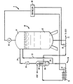
- a pressure sensor 16 is provided typically within storage tank 10 to sense pressure within its headspace region 14. Pressure sensor 16 is linked to a controller 18 which is responsive to a pressure signal generated by pressure sensor 16 to control remotely operated valves 20 and 22. When pressure within headspace region 14 reaches a pre-determined value, the signal generated by pressure sensor 16 causes controller 18 to set control valve 20 into an open position. Vapour flows from headspace region 14 via a conduit 24 to a condensation tank 26. The opening of control valve 20 allows liquid to flow from the bottom of storage tank 10 into a conduit 28 which by indirect heat exchange causes headspace vapour within condensation tank 26 to condense into a liquid shown in the drawings as condensed headspace vapour 29.
- control valve 22 When the pressure falls below the pre-determined value, control valve 22 opens and control valve 20 closes.
- the opening of control valve 22 causes the subsidiary stream of the condensed headspace vapour 29 to flow within a pressure building circuit 30 (having an ambient vaporiser 31) and pressurise condensation tank 26.
- This pressure drives or urges the condensed headspace vapour 29 from condensation tank 26 through return line 32 back into storage tank 14.
- condensed headspace vapour 29 is illustrated as flowing back in to headspace region 14, it could by appropriate piping flow back into multi-component liquid cryogen 12.
- controller 18 commands control valve 22 to close.
- a check (non-return) valve 34 within conduit 24 prevents backflow of vapour to the headspace 14.
- the check valve 34 could be replaced with a solenoid or other type of control valve.
- the pressure building circuit 30 uses an ambient vaporiser 31 to generate the pressure, alternatives, such as an electric heater, may be used to vaporise the cryogen.
- the illustrated apparatus enables the pressure in the storage tank 10 to be regulated and the composition of the liquid cryogen held therein to be maintained constant with some degree of consistency.
- control strategies could be employed to optimise the venting process and maintain pressure. For example, the level of the condensate or the temperature of the vent gas could be monitored to determine that the condensate level had risen too far. Appropriate control logic could then cause a switch to the pressure building circuit to pump the liquid back into the storage vessel, prior to further venting. Alternatively, a timer could be employed where pressure building/pumping could be initiated after a fixed time, then switching back to further venting for a fixed time.
Description
- The present invention relates to an apparatus for storing a multi-component cryogenic liquid within a storage tank. More particularly, the present invention relates to such an apparatus in which headspace vapour within the storage tank is condensed by indirect heat transfer with the cryogenic liquid. More particularly, the present invention relates to such an apparatus in which the headspace vapour is condensed within an external condensation tank and the resulting condensate is returned to the storage vessel by a pressure building circuit.
- Cryogenic storage vessels and dewars are used to store cryogenic liquids, for instance, liquefied atmospheric gases, either at their point of use or for use in the transport of such cryogenic liquids. Although such storage tanks and dewars are insulated, there is still heat leakage into the storage tank or dewar. This heat leakage causes vaporisation of the liquid cryogen. Typically, the vapour is vented from a headspace region of the tank to prevent overpressurisation of the tank. Where the liquid cryogen is a multi-component mixture, for instance air, the venting of the vapour phase presents a problem because the more volatile components will vaporise before the less volatile components. As a result, the liquid being stored will have an ever increasing concentration of the less volatile components. For instance, if the liquid cryogen being stored is liquid air, nitrogen (as well as other components of the air but at a lower concentration) will be vented to cause the liquid to have an ever increasing oxygen content.
- In order to overcome this problem, US-A-3,260,060 discloses a cryogenic dewar in which liquid is vented through a heat exchanger located within the headspace region of the dewar. As pressure within the dewar increases, the liquid passing through the heat exchanger condenses the vapour to stabilise the concentration of the liquid. Since the liquid, now vaporised, is at the same concentration of the bulk liquid, there is no concentration change.
- The problem with the cryogenic dewar illustrated in US-A-3,260,060 is that it involves manufacturing dewars with heat exchangers in the headspace region and thus, cannot easily serve as a retrofit to existing cryogenic dewars. As will be discussed, the present invention solves the retrofitting problem by providing a cryogenic storage apparatus that is easily adapted as a retrofit for conventional cryogenic storage tanks and dewars.
- According to the present invention there is provided an apparatus for storing a multi-component cryogenic liquid comprising, a storage tank for said multi-component cryogenic liquid; a condensation tank located external to said storage tank for condensing headspace vapour; heat exchange means located within said condensation tank for condensing said headspace vapour, said heat exchange means in communication with said storage tank and venting to atmosphere so that a liquid stream from said storage tank is able, in use, to vaporise within said heat exchange means in indirect heat exchange with condensing headspace vapour and vent to atmosphere; first actuable valve means for permitting said liquid stream to flow to said heat exchange means when pressure within said headspace region is above a predetermined value; said condensation tank having an inlet communicating with the headspace of the storage tank and an outlet communicating with the storage tank; and means for driving said condensed headspace vapour back into said storage tank after said pressure falls below said predetermined value.
- The term "multi-component" as used herein means having two or more components.
- Since the condensation occurs within an external condensation tank, such external condensation tank can be retrofitted with appropriate plumbing to existing storage tanks and dewars.
- The apparatus according to the invention will now be described by way of example with reference to the accompanying drawing.
- With reference to the Figure, an apparatus 1 in accordance with the present invention is provided for storing a multi-component cryogenic liquid, for instance, liquid air. Apparatus 1 utilises a
conventional storage tank 10 containing a multi-componentliquid cryogen 12.Storage tank 10, is thermally insulated in a conventional manner. Nonetheless, there is still some "heat inleakage" into thetank 10. Due to this heat leakage into thetank 10,liquid cryogen 12 vaporises to form vapour within aheadspace region 14 thereof.Liquid cryogen 12 flows to a user through conduit 1 5. - A
pressure sensor 16 is provided typically withinstorage tank 10 to sense pressure within itsheadspace region 14.Pressure sensor 16 is linked to acontroller 18 which is responsive to a pressure signal generated bypressure sensor 16 to control remotely operatedvalves headspace region 14 reaches a pre-determined value, the signal generated bypressure sensor 16 causescontroller 18 to setcontrol valve 20 into an open position. Vapour flows fromheadspace region 14 via aconduit 24 to acondensation tank 26. The opening ofcontrol valve 20 allows liquid to flow from the bottom ofstorage tank 10 into aconduit 28 which by indirect heat exchange causes headspace vapour withincondensation tank 26 to condense into a liquid shown in the drawings as condensedheadspace vapour 29. - When the pressure falls below the pre-determined value,
control valve 22 opens andcontrol valve 20 closes. The opening ofcontrol valve 22 causes the subsidiary stream of the condensedheadspace vapour 29 to flow within a pressure building circuit 30 (having an ambient vaporiser 31) andpressurise condensation tank 26. This pressure drives or urges the condensedheadspace vapour 29 fromcondensation tank 26 throughreturn line 32 back intostorage tank 14. It is to be noted that although condensedheadspace vapour 29 is illustrated as flowing back in toheadspace region 14, it could by appropriate piping flow back into multi-componentliquid cryogen 12. As the pressure approaches a pre-determined value,controller 18commands control valve 22 to close. A check (non-return)valve 34 withinconduit 24 prevents backflow of vapour to theheadspace 14. - The
check valve 34 could be replaced with a solenoid or other type of control valve. Although thepressure building circuit 30 uses anambient vaporiser 31 to generate the pressure, alternatives, such as an electric heater, may be used to vaporise the cryogen. - The illustrated apparatus enables the pressure in the
storage tank 10 to be regulated and the composition of the liquid cryogen held therein to be maintained constant with some degree of consistency. - In addition to the foregoing, numerous control strategies could be employed to optimise the venting process and maintain pressure. For example, the level of the condensate or the temperature of the vent gas could be monitored to determine that the condensate level had risen too far. Appropriate control logic could then cause a switch to the pressure building circuit to pump the liquid back into the storage vessel, prior to further venting. Alternatively, a timer could be employed where pressure building/pumping could be initiated after a fixed time, then switching back to further venting for a fixed time.
Claims (7)
- An apparatus for storing a multi-component cryogenic liquid comprising:a storage tank (10) for said multi-component cryogenic liquid (12);a condensation tank (26) located external to said storage tank for condensing headspace vapour (14);heat exchange means (18) located within said condensation tank (26) for condensing said headspace vapour (14), said heat exchange means (18) in communication with said storage tank (10) and venting to atmosphere so that a liquid stream from said storage tank is able, in use, to vaporise within said heat exchange means in indirect heat exchange with condensing headspace vapour and vent to atmosphere;first actuable valve means (20) for permitting said liquid stream to flow to said heat exchange means when pressure within said headspace region is above a predetermined value;said condensation tank having an inlet communicating with the headspace (14) of the storage tank and an outlet communicating with the storage tank; andmean (36) for driving said condensed headspace vapour back into said storage tank after said pressure falls below said predetermined value.
- Apparatus according to claim 1, wherein said outlet communicates with the headspace of the storage tank.
- Apparatus according to claim 1 or claim 2, wherein said condensed headspace vapour driving means comprises actuable means for building pressure within said condensation tank.
- Apparatus according to claim 3, wherein said actuable pressure building means comprises a pressure building circuit to vaporise a portion of the condensed headspace vapour and thereby pressurise said condensation tank.
- Apparatus according to claim 4, wherein:
said actuable pressure building means includes a second actuable valve means (22). - Apparatus according to claim 5, additionally includinga pressure sensor (16) for sensing said headspace pressure of said storage tank to generate a signal related to said pressure;a controller (18), responsive to said signal, for remotely controlling said first (20) and second (22) valve means, the arrangement being such that above said predetermined pressure the first valve means (20) is in an open position and the second valve means (22) is in a closed position and below said predetermined pressure the second valve means (22) is in an open position and the first valve means (20) is in a closed position.
- Apparatus according to any one of the preceding claims, in which the inlet to the condensation tank communicates with the headspace via a conduit (24) in which is located a check valve to prevent backflow of vapour.
Applications Claiming Priority (2)
| Application Number | Priority Date | Filing Date | Title |
|---|---|---|---|
| US08/547,764 US5571231A (en) | 1995-10-25 | 1995-10-25 | Apparatus for storing a multi-component cryogenic liquid |
| US547764 | 1995-10-25 |
Publications (3)
| Publication Number | Publication Date |
|---|---|
| EP0770816A2 EP0770816A2 (en) | 1997-05-02 |
| EP0770816A3 EP0770816A3 (en) | 1997-05-07 |
| EP0770816B1 true EP0770816B1 (en) | 2000-08-09 |
Family
ID=24186031
Family Applications (1)
| Application Number | Title | Priority Date | Filing Date |
|---|---|---|---|
| EP96307641A Expired - Lifetime EP0770816B1 (en) | 1995-10-25 | 1996-10-22 | Apparatus for storing a multi-component cryogenic liquid |
Country Status (10)
| Country | Link |
|---|---|
| US (1) | US5571231A (en) |
| EP (1) | EP0770816B1 (en) |
| JP (1) | JPH09166292A (en) |
| CN (1) | CN1068421C (en) |
| AU (1) | AU703555B2 (en) |
| CA (1) | CA2184219C (en) |
| DE (1) | DE69609690D1 (en) |
| HK (1) | HK1014748A1 (en) |
| PL (1) | PL316647A1 (en) |
| ZA (1) | ZA968034B (en) |
Families Citing this family (32)
| Publication number | Priority date | Publication date | Assignee | Title |
|---|---|---|---|---|
| GB9506652D0 (en) * | 1995-03-31 | 1995-05-24 | Cryogenic Technology Ltd | Supplying liquid cryogen to cryosurgical apparatus |
| US5987896A (en) * | 1997-08-15 | 1999-11-23 | Panadea Medical Laboratories | System and method for regulating the flow of a fluid refrigerant to a cooling element |
| US5934080A (en) * | 1997-09-17 | 1999-08-10 | Praxair Technology, Inc. | Fog generation using liquid synthetic air |
| US6000226A (en) * | 1998-07-30 | 1999-12-14 | The Boc Group, Inc. | Method and apparatus for storing and dispensing a liquid composed of oxygen containing mixture |
| DE19920314A1 (en) * | 1999-05-03 | 2000-11-09 | Linde Tech Gase Gmbh | Method and device for dispensing liquefied gas |
| US6584998B1 (en) * | 2000-03-31 | 2003-07-01 | Innovative Engineered Solutions, Llc | Apparatus and method for regulating gas flow |
| US6408632B1 (en) | 2000-06-28 | 2002-06-25 | Michael D. Cashin | Freezer and plant gas system |
| DE10060791A1 (en) * | 2000-12-07 | 2002-06-13 | Bayerische Motoren Werke Ag | Method and device for delivering a cryogenically stored fuel |
| JP2003106498A (en) * | 2001-09-28 | 2003-04-09 | Toho Gas Co Ltd | Bog re-liquefaction and recovery system for lng tank |
| US6430938B1 (en) | 2001-10-18 | 2002-08-13 | Praxair Technology, Inc. | Cryogenic vessel system with pulse tube refrigeration |
| US6453677B1 (en) | 2002-04-05 | 2002-09-24 | Praxair Technology, Inc. | Magnetic refrigeration cryogenic vessel system |
| GB0320474D0 (en) * | 2003-09-01 | 2003-10-01 | Cryostar France Sa | Controlled storage of liquefied gases |
| NO20035047D0 (en) * | 2003-11-13 | 2003-11-13 | Hamworthy Kse Gas Systems As | Apparatus and method for temperature control of gas condensation |
| DE102005001277A1 (en) * | 2005-01-11 | 2006-07-20 | Linde Ag | Plant and process for the recondensation of cold gas |
| DE102005028199A1 (en) * | 2005-06-17 | 2006-12-21 | Linde Ag | Storage container for kyrogenic media |
| US20070006597A1 (en) * | 2005-07-06 | 2007-01-11 | Zia Jalal H | Cryogenic tank system |
| US20070130962A1 (en) * | 2005-12-12 | 2007-06-14 | Blalock Clayton E | System and Method for Storing Cryogenic Liquid Air |
| US20090071171A1 (en) * | 2007-09-18 | 2009-03-19 | Jalal Hunain Zia | Cryogenic liquid storage method and system |
| CN101684890B (en) * | 2008-09-26 | 2012-01-11 | 周立军 | Low pressure storage high pressure transmission and supply cryogenic tank |
| CN101684889B (en) * | 2008-09-26 | 2011-11-16 | 周立军 | Cryogenic tank |
| CA2653643C (en) * | 2009-02-26 | 2010-08-31 | Westport Power Inc. | Pressure control system and method |
| JP5795767B2 (en) * | 2009-09-28 | 2015-10-14 | コーニンクレッカ フィリップス エヌ ヴェ | System and method for liquefying and storing fluids |
| AU2010299505A1 (en) * | 2009-09-28 | 2012-05-24 | Koninklijke Philips Electronics N.V. | System and method for liquefying and storing a fluid |
| US20120102978A1 (en) * | 2010-06-03 | 2012-05-03 | Lee Ron C | Liquefied natural gas refueling system |
| CN104937325B (en) * | 2012-12-14 | 2017-01-25 | 瓦锡兰芬兰有限公司 | Method of starting gas delivery from liquefied gas fuel system to gas operated engine and liquefied gas fuel system for gas operated engine |
| FR3005135B1 (en) * | 2013-04-30 | 2019-03-29 | Cryostar Sas | METHOD AND DEVICE FOR REFUELING CRYOGENIC LIQUID, IN PARTICULAR LIQUEFIED NATURAL GAS |
| CN104132239B (en) * | 2014-07-29 | 2016-08-24 | 江苏克劳特低温技术有限公司 | A kind of cryogenic gas condensation cycle system and method |
| CN104279423A (en) * | 2014-09-23 | 2015-01-14 | 中广核中科海维科技发展有限公司 | Liquid ammonia storage safety alarm device |
| CN105927847B (en) * | 2016-06-17 | 2019-01-18 | 珠海格力电器股份有限公司 | Gas storage tank device and compressor with it |
| US10030611B2 (en) | 2016-08-05 | 2018-07-24 | Caterpillar Inc. | Fuel delivery system |
| CN106839543A (en) * | 2017-03-15 | 2017-06-13 | 烟台冰轮股份有限公司 | A kind of CO2Refrigeration system working medium tapping equipment and discharge control method |
| CN107726039A (en) * | 2017-10-20 | 2018-02-23 | 广东锐捷安全技术股份有限公司 | A kind of container group for liquid gas low-temperature storage |
Family Cites Families (15)
| Publication number | Priority date | Publication date | Assignee | Title |
|---|---|---|---|---|
| US2944405A (en) * | 1955-10-27 | 1960-07-12 | Union Tank Car Co | Conservation arrangement |
| US3260060A (en) | 1964-08-26 | 1966-07-12 | Ryan Ind Inc | Dewar for liquid air and/or other multicomponent cryogenic liquids |
| FR1448598A (en) * | 1964-09-30 | 1966-08-05 | Philips Nv | Liquefaction plant for a gas mixture |
| DE1251233B (en) * | 1965-01-14 | |||
| US3303660A (en) * | 1965-09-27 | 1967-02-14 | Clyde H O Berg | Process and apparatus for cryogenic storage |
| US3371497A (en) * | 1966-08-05 | 1968-03-05 | Air Prod & Chem | Maintaining constant composition in a volatile multi-component liquid |
| US3714790A (en) * | 1971-04-13 | 1973-02-06 | Fmc Corp | Apparatus and method for handling volatile liquids |
| FR2406782A1 (en) * | 1977-10-20 | 1979-05-18 | Air Liquide | Cryogenic storage system for liquefied gas - uses cooling effect of evaporation of small quantity of liquid to control pressure level in thermally insulated vessel |
| US4276749A (en) * | 1980-04-16 | 1981-07-07 | Phillips Petroleum Company | Storage system for liquefied gases |
| JPS5891996A (en) * | 1981-11-26 | 1983-06-01 | Ishikawajima Harima Heavy Ind Co Ltd | Processing device of low temperature liquefied gas |
| FR2572161B1 (en) * | 1984-10-19 | 1988-02-26 | Air Liquide | CONTAINER FOR CRYOGENIC MIXTURE |
| FR2572162B1 (en) * | 1984-10-19 | 1988-02-26 | Air Liquide | CONTAINER FOR CRYOGENIC MIXTURE AND LIQUID DRAWING METHOD |
| FR2588947B1 (en) * | 1985-10-21 | 1989-02-10 | Distrigaz Sa | PROCESS FOR MAINTAINING THE COMPOSITION OF THE CONSTANT STORED PRODUCT IN LOW TEMPERATURE LIQUEFIED GAS STORAGE |
| US4727723A (en) * | 1987-06-24 | 1988-03-01 | The M. W. Kellogg Company | Method for sub-cooling a normally gaseous hydrocarbon mixture |
| US5076822A (en) * | 1990-05-07 | 1991-12-31 | Hewitt J Paul | Vapor recovery system |
-
1995
- 1995-10-25 US US08/547,764 patent/US5571231A/en not_active Expired - Fee Related
-
1996
- 1996-08-27 CA CA002184219A patent/CA2184219C/en not_active Expired - Fee Related
- 1996-09-10 AU AU65578/96A patent/AU703555B2/en not_active Ceased
- 1996-09-23 ZA ZA968034A patent/ZA968034B/en unknown
- 1996-10-17 JP JP8274316A patent/JPH09166292A/en not_active Withdrawn
- 1996-10-21 CN CN96122654A patent/CN1068421C/en not_active Expired - Fee Related
- 1996-10-22 DE DE69609690T patent/DE69609690D1/en not_active Expired - Lifetime
- 1996-10-22 EP EP96307641A patent/EP0770816B1/en not_active Expired - Lifetime
- 1996-10-23 PL PL96316647A patent/PL316647A1/en unknown
-
1998
- 1998-12-28 HK HK98116097A patent/HK1014748A1/en not_active IP Right Cessation
Also Published As
| Publication number | Publication date |
|---|---|
| CA2184219C (en) | 1999-07-20 |
| JPH09166292A (en) | 1997-06-24 |
| CA2184219A1 (en) | 1997-04-26 |
| DE69609690D1 (en) | 2000-09-14 |
| EP0770816A3 (en) | 1997-05-07 |
| AU703555B2 (en) | 1999-03-25 |
| CN1068421C (en) | 2001-07-11 |
| ZA968034B (en) | 1997-04-07 |
| AU6557896A (en) | 1997-05-01 |
| US5571231A (en) | 1996-11-05 |
| EP0770816A2 (en) | 1997-05-02 |
| PL316647A1 (en) | 1997-04-28 |
| CN1156231A (en) | 1997-08-06 |
| HK1014748A1 (en) | 1999-09-30 |
Similar Documents
| Publication | Publication Date | Title |
|---|---|---|
| EP0770816B1 (en) | Apparatus for storing a multi-component cryogenic liquid | |
| US5613366A (en) | System and method for regulating the temperature of cryogenic liquids | |
| US6505469B1 (en) | Gas dispensing system for cryogenic liquid vessels | |
| US5590535A (en) | Process and apparatus for conditioning cryogenic fuel to establish a selected equilibrium pressure | |
| US5197548A (en) | Fire extinguishing device with storage tank for a low-boiling liquefied gas which serves as extinguishing agent | |
| US6474078B2 (en) | Pumping system and method for pumping fluids | |
| AU666065B2 (en) | Subcooling method and apparatus | |
| CN107850260A (en) | It is operably connected to the equipment of the pumping equipment of the thermal insulation barrier of the tank for storing liquefied gas | |
| US4592205A (en) | Low pressure cryogenic liquid delivery system | |
| US3260060A (en) | Dewar for liquid air and/or other multicomponent cryogenic liquids | |
| US6230516B1 (en) | Apparatus for mixing a multiple constituent liquid into a container and method | |
| LT3271B (en) | A method and arrangement for adding an odorant to a consumer gas | |
| US6584998B1 (en) | Apparatus and method for regulating gas flow | |
| US5778680A (en) | Apparatus for storing a multi-component cryogenic mixture within a container | |
| CA2275847C (en) | Method and apparatus for storing and dispensing a liquid composed of oxygen containing mixture | |
| US5291741A (en) | Liquid helium topping-up apparatus | |
| US20070130962A1 (en) | System and Method for Storing Cryogenic Liquid Air | |
| GB2098874A (en) | Condensation method and apparatus | |
| US3318104A (en) | Method and apparatus for storing low-boiling liquids | |
| US5839285A (en) | Fuel gas delivery system | |
| CN212107873U (en) | Recondensor suitable for liquefied natural gas receiving station | |
| KR940008224Y1 (en) | Lpg tank custody | |
| KR20220135206A (en) | Method and device for reliquefaction of bog | |
| JP2024512400A (en) | Method and apparatus for reliquefying BOG | |
| JPS6225599Y2 (en) |
Legal Events
| Date | Code | Title | Description |
|---|---|---|---|
| PUAI | Public reference made under article 153(3) epc to a published international application that has entered the european phase |
Free format text: ORIGINAL CODE: 0009012 |
|
| PUAL | Search report despatched |
Free format text: ORIGINAL CODE: 0009013 |
|
| AK | Designated contracting states |
Kind code of ref document: A2 Designated state(s): BE DE FR GB IE IT NL SE |
|
| AK | Designated contracting states |
Kind code of ref document: A3 Designated state(s): BE DE FR GB IE IT NL SE |
|
| 17P | Request for examination filed |
Effective date: 19971001 |
|
| GRAG | Despatch of communication of intention to grant |
Free format text: ORIGINAL CODE: EPIDOS AGRA |
|
| 17Q | First examination report despatched |
Effective date: 19990908 |
|
| GRAG | Despatch of communication of intention to grant |
Free format text: ORIGINAL CODE: EPIDOS AGRA |
|
| GRAG | Despatch of communication of intention to grant |
Free format text: ORIGINAL CODE: EPIDOS AGRA |
|
| GRAH | Despatch of communication of intention to grant a patent |
Free format text: ORIGINAL CODE: EPIDOS IGRA |
|
| GRAH | Despatch of communication of intention to grant a patent |
Free format text: ORIGINAL CODE: EPIDOS IGRA |
|
| GRAA | (expected) grant |
Free format text: ORIGINAL CODE: 0009210 |
|
| AK | Designated contracting states |
Kind code of ref document: B1 Designated state(s): BE DE FR GB IE IT NL SE |
|
| PG25 | Lapsed in a contracting state [announced via postgrant information from national office to epo] |
Ref country code: NL Free format text: LAPSE BECAUSE OF FAILURE TO SUBMIT A TRANSLATION OF THE DESCRIPTION OR TO PAY THE FEE WITHIN THE PRESCRIBED TIME-LIMIT Effective date: 20000809 Ref country code: IT Free format text: LAPSE BECAUSE OF FAILURE TO SUBMIT A TRANSLATION OF THE DESCRIPTION OR TO PAY THE FEE WITHIN THE PRE;WARNING: LAPSES OF ITALIAN PATENTS WITH EFFECTIVE DATE BEFORE 2007 MAY HAVE OCCURRED AT ANY TIME BEFORE 2007. THE CORRECT EFFECTIVE DATE MAY BE DIFFERENT FROM THE ONE RECORDED.SCRIBED TIME-LIMIT Effective date: 20000809 Ref country code: FR Free format text: LAPSE BECAUSE OF FAILURE TO SUBMIT A TRANSLATION OF THE DESCRIPTION OR TO PAY THE FEE WITHIN THE PRESCRIBED TIME-LIMIT Effective date: 20000809 Ref country code: BE Free format text: LAPSE BECAUSE OF FAILURE TO SUBMIT A TRANSLATION OF THE DESCRIPTION OR TO PAY THE FEE WITHIN THE PRESCRIBED TIME-LIMIT Effective date: 20000809 |
|
| REG | Reference to a national code |
Ref country code: IE Ref legal event code: FG4D |
|
| REF | Corresponds to: |
Ref document number: 69609690 Country of ref document: DE Date of ref document: 20000914 |
|
| PGFP | Annual fee paid to national office [announced via postgrant information from national office to epo] |
Ref country code: FR Payment date: 20001002 Year of fee payment: 5 |
|
| PGFP | Annual fee paid to national office [announced via postgrant information from national office to epo] |
Ref country code: SE Payment date: 20001003 Year of fee payment: 5 Ref country code: DE Payment date: 20001003 Year of fee payment: 5 |
|
| PGFP | Annual fee paid to national office [announced via postgrant information from national office to epo] |
Ref country code: GB Payment date: 20001004 Year of fee payment: 5 |
|
| PGFP | Annual fee paid to national office [announced via postgrant information from national office to epo] |
Ref country code: NL Payment date: 20001006 Year of fee payment: 5 |
|
| PGFP | Annual fee paid to national office [announced via postgrant information from national office to epo] |
Ref country code: IE Payment date: 20001031 Year of fee payment: 5 |
|
| PG25 | Lapsed in a contracting state [announced via postgrant information from national office to epo] |
Ref country code: SE Free format text: LAPSE BECAUSE OF FAILURE TO SUBMIT A TRANSLATION OF THE DESCRIPTION OR TO PAY THE FEE WITHIN THE PRESCRIBED TIME-LIMIT Effective date: 20001109 |
|
| PG25 | Lapsed in a contracting state [announced via postgrant information from national office to epo] |
Ref country code: DE Free format text: LAPSE BECAUSE OF FAILURE TO SUBMIT A TRANSLATION OF THE DESCRIPTION OR TO PAY THE FEE WITHIN THE PRESCRIBED TIME-LIMIT Effective date: 20001110 |
|
| PGFP | Annual fee paid to national office [announced via postgrant information from national office to epo] |
Ref country code: BE Payment date: 20001116 Year of fee payment: 5 |
|
| NLV1 | Nl: lapsed or annulled due to failure to fulfill the requirements of art. 29p and 29m of the patents act | ||
| EN | Fr: translation not filed | ||
| PLBE | No opposition filed within time limit |
Free format text: ORIGINAL CODE: 0009261 |
|
| STAA | Information on the status of an ep patent application or granted ep patent |
Free format text: STATUS: NO OPPOSITION FILED WITHIN TIME LIMIT |
|
| 26N | No opposition filed | ||
| PG25 | Lapsed in a contracting state [announced via postgrant information from national office to epo] |
Ref country code: IE Free format text: LAPSE BECAUSE OF FAILURE TO SUBMIT A TRANSLATION OF THE DESCRIPTION OR TO PAY THE FEE WITHIN THE PRESCRIBED TIME-LIMIT Effective date: 20011022 Ref country code: GB Free format text: LAPSE BECAUSE OF NON-PAYMENT OF DUE FEES Effective date: 20011022 |
|
| REG | Reference to a national code |
Ref country code: GB Ref legal event code: IF02 |
|
| GBPC | Gb: european patent ceased through non-payment of renewal fee |
Effective date: 20011022 |
|
| REG | Reference to a national code |
Ref country code: IE Ref legal event code: MM4A |