EP0770804A2 - Rotary slide valve assembly - Google Patents
Rotary slide valve assembly Download PDFInfo
- Publication number
- EP0770804A2 EP0770804A2 EP96306710A EP96306710A EP0770804A2 EP 0770804 A2 EP0770804 A2 EP 0770804A2 EP 96306710 A EP96306710 A EP 96306710A EP 96306710 A EP96306710 A EP 96306710A EP 0770804 A2 EP0770804 A2 EP 0770804A2
- Authority
- EP
- European Patent Office
- Prior art keywords
- housing
- stem
- bore
- valve element
- coupler
- Prior art date
- Legal status (The legal status is an assumption and is not a legal conclusion. Google has not performed a legal analysis and makes no representation as to the accuracy of the status listed.)
- Withdrawn
Links
Images


Classifications
-
- F—MECHANICAL ENGINEERING; LIGHTING; HEATING; WEAPONS; BLASTING
- F16—ENGINEERING ELEMENTS AND UNITS; GENERAL MEASURES FOR PRODUCING AND MAINTAINING EFFECTIVE FUNCTIONING OF MACHINES OR INSTALLATIONS; THERMAL INSULATION IN GENERAL
- F16K—VALVES; TAPS; COCKS; ACTUATING-FLOATS; DEVICES FOR VENTING OR AERATING
- F16K11/00—Multiple-way valves, e.g. mixing valves; Pipe fittings incorporating such valves
-
- F—MECHANICAL ENGINEERING; LIGHTING; HEATING; WEAPONS; BLASTING
- F16—ENGINEERING ELEMENTS AND UNITS; GENERAL MEASURES FOR PRODUCING AND MAINTAINING EFFECTIVE FUNCTIONING OF MACHINES OR INSTALLATIONS; THERMAL INSULATION IN GENERAL
- F16K—VALVES; TAPS; COCKS; ACTUATING-FLOATS; DEVICES FOR VENTING OR AERATING
- F16K27/00—Construction of housing; Use of materials therefor
- F16K27/04—Construction of housing; Use of materials therefor of sliding valves
- F16K27/044—Construction of housing; Use of materials therefor of sliding valves slide valves with flat obturating members
- F16K27/045—Construction of housing; Use of materials therefor of sliding valves slide valves with flat obturating members with pivotal obturating members
-
- F—MECHANICAL ENGINEERING; LIGHTING; HEATING; WEAPONS; BLASTING
- F16—ENGINEERING ELEMENTS AND UNITS; GENERAL MEASURES FOR PRODUCING AND MAINTAINING EFFECTIVE FUNCTIONING OF MACHINES OR INSTALLATIONS; THERMAL INSULATION IN GENERAL
- F16K—VALVES; TAPS; COCKS; ACTUATING-FLOATS; DEVICES FOR VENTING OR AERATING
- F16K3/00—Gate valves or sliding valves, i.e. cut-off apparatus with closing members having a sliding movement along the seat for opening and closing
- F16K3/02—Gate valves or sliding valves, i.e. cut-off apparatus with closing members having a sliding movement along the seat for opening and closing with flat sealing faces; Packings therefor
- F16K3/04—Gate valves or sliding valves, i.e. cut-off apparatus with closing members having a sliding movement along the seat for opening and closing with flat sealing faces; Packings therefor with pivoted closure members
- F16K3/06—Gate valves or sliding valves, i.e. cut-off apparatus with closing members having a sliding movement along the seat for opening and closing with flat sealing faces; Packings therefor with pivoted closure members in the form of closure plates arranged between supply and discharge passages
- F16K3/08—Gate valves or sliding valves, i.e. cut-off apparatus with closing members having a sliding movement along the seat for opening and closing with flat sealing faces; Packings therefor with pivoted closure members in the form of closure plates arranged between supply and discharge passages with circular plates rotatable around their centres
-
- Y—GENERAL TAGGING OF NEW TECHNOLOGICAL DEVELOPMENTS; GENERAL TAGGING OF CROSS-SECTIONAL TECHNOLOGIES SPANNING OVER SEVERAL SECTIONS OF THE IPC; TECHNICAL SUBJECTS COVERED BY FORMER USPC CROSS-REFERENCE ART COLLECTIONS [XRACs] AND DIGESTS
- Y10—TECHNICAL SUBJECTS COVERED BY FORMER USPC
- Y10T—TECHNICAL SUBJECTS COVERED BY FORMER US CLASSIFICATION
- Y10T137/00—Fluid handling
- Y10T137/5109—Convertible
- Y10T137/5196—Unit orientable in a single location between plural positions
-
- Y—GENERAL TAGGING OF NEW TECHNOLOGICAL DEVELOPMENTS; GENERAL TAGGING OF CROSS-SECTIONAL TECHNOLOGIES SPANNING OVER SEVERAL SECTIONS OF THE IPC; TECHNICAL SUBJECTS COVERED BY FORMER USPC CROSS-REFERENCE ART COLLECTIONS [XRACs] AND DIGESTS
- Y10—TECHNICAL SUBJECTS COVERED BY FORMER USPC
- Y10T—TECHNICAL SUBJECTS COVERED BY FORMER US CLASSIFICATION
- Y10T137/00—Fluid handling
- Y10T137/598—With repair, tapping, assembly, or disassembly means
- Y10T137/6011—Assembling, disassembling, or removing cartridge type valve [e.g., insertable and removable as a unit, etc.]
- Y10T137/6014—Faucet type [e.g., domestic water use, etc.]
-
- Y—GENERAL TAGGING OF NEW TECHNOLOGICAL DEVELOPMENTS; GENERAL TAGGING OF CROSS-SECTIONAL TECHNOLOGIES SPANNING OVER SEVERAL SECTIONS OF THE IPC; TECHNICAL SUBJECTS COVERED BY FORMER USPC CROSS-REFERENCE ART COLLECTIONS [XRACs] AND DIGESTS
- Y10—TECHNICAL SUBJECTS COVERED BY FORMER USPC
- Y10T—TECHNICAL SUBJECTS COVERED BY FORMER US CLASSIFICATION
- Y10T137/00—Fluid handling
- Y10T137/7504—Removable valve head and seat unit
- Y10T137/7613—Threaded into valve casing
-
- Y—GENERAL TAGGING OF NEW TECHNOLOGICAL DEVELOPMENTS; GENERAL TAGGING OF CROSS-SECTIONAL TECHNOLOGIES SPANNING OVER SEVERAL SECTIONS OF THE IPC; TECHNICAL SUBJECTS COVERED BY FORMER USPC CROSS-REFERENCE ART COLLECTIONS [XRACs] AND DIGESTS
- Y10—TECHNICAL SUBJECTS COVERED BY FORMER USPC
- Y10T—TECHNICAL SUBJECTS COVERED BY FORMER US CLASSIFICATION
- Y10T137/00—Fluid handling
- Y10T137/7504—Removable valve head and seat unit
- Y10T137/7668—Retained by bonnet or closure
-
- Y—GENERAL TAGGING OF NEW TECHNOLOGICAL DEVELOPMENTS; GENERAL TAGGING OF CROSS-SECTIONAL TECHNOLOGIES SPANNING OVER SEVERAL SECTIONS OF THE IPC; TECHNICAL SUBJECTS COVERED BY FORMER USPC CROSS-REFERENCE ART COLLECTIONS [XRACs] AND DIGESTS
- Y10—TECHNICAL SUBJECTS COVERED BY FORMER USPC
- Y10T—TECHNICAL SUBJECTS COVERED BY FORMER US CLASSIFICATION
- Y10T137/00—Fluid handling
- Y10T137/8593—Systems
- Y10T137/86493—Multi-way valve unit
- Y10T137/86863—Rotary valve unit
- Y10T137/86871—Plug
Definitions
- the present invention relates to a valve assembly and, in particular, to a non-rise valve assembly.
- Faucets which are typically used in a lavatory or a kitchen may use a valve with a single-handle control or a two-handle control.
- the valves are located on each side of a spout of the faucet and are referred to as the left side valve, for controlling the supply of hot water, and the right side valve for controlling the supply of cold water.
- the left side valve for controlling the supply of hot water
- the right side valve for controlling the supply of cold water.
- one type of two-handle valve which has been in use includes a stem which is threadedly mounted in a bonnet.
- valves used in a two-handle faucet is a non-rise valve and employs two ceramic discs which are always in interfacing engagement and which are formed with openings to facilitate the flow of water therethrough.
- the valve is closed to prevent the flow of water therethrough.
- the valve handle and associated stem are turned, one of the discs which is attached to the stem is rotated relative to the other disc while the two discs remain in interfacing engagement.
- the openings of the discs are aligned and water is allowed to flow through the openings and out of the spout.
- the stem of the valve does not rise as the valve is opened, in contrast to the valve with the threadedly mounted stem noted above.
- a few examples of the many valves of the ceramic type are disclosed in U.S. Patents Nos. 3,780,758; 3,831,621 and 5,174,324.
- the stem is freely rotatable within the bonnet in a clockwise direction and a counterclockwise direction. Therefore, a given design of a ceramic valve could be used on both sides of a two-handle faucet, that is as a right side valve and as a left side valve to provide the turning direction typically associated with a cold water valve on the right side of the faucet and a hot water valve on the left side of the faucet.
- a turning limit stop must be employed to limit the turning of the valve in each direction to one-quarter of a full turn.
- a reversible stop is used with each valve to limit the turning of the stem in one direction or the other depending on whether the valve is being used on the right side or the left side of the faucet.
- An example of a reversible stop which is used for this purpose is disclosed in U.S. Patent No. 3,831,621.
- the components of the valves are assembled in a factory to form the valves.
- the reversible stops are assembled so that each valve is either a hot water or a cold water valve and the valves are segregated accordingly.
- a hot water valve is then assembled into one of a pair of spaced end bodies on opposite ends of an underbody which is to the left of a centre body thereof.
- a cold water valve is then assembled into the other end body which is to the right of the centre body.
- the underbody is then assembled with other elements to form a faucet.
- the faucet is packaged and shipped, eventually, to an installation site where it is installed in a plumbing system.
- valve During the period immediately following the assembly of the components of the valve, the valve is transported within the factory to various stations for further processing. Also, individual valves may be packaged and sold as replacement units for installation with existing, previously installed faucets.
- bottom seal element is assembled at the bottom of two-handle valve assemblies of the type described above.
- the bottom seal must be composed of a material which provides a water-tight seal at the bottom of the valve assembly while placing a limited stress on valving components which allow the valve assembly to be operated with relative and comfortable ease.
- the bottom seals currently used include a compliant member which is composed of a relatively expensive material. Thus, it is important that provision be made for providing an effective bottom seal which is relatively inexpensive.
- a homeowner may wish to convert a faucet from a knob-handle unit to a lever-handle unit.
- the knobs are removed and replaced by levers.
- the reversible stops are situated within the valve assembly in a precise manner to accommodate the conventional turning for the hot and cold water valves in the same direction, that is clockwise to close for both the hot and cold water valves.
- the hot and cold levers extend in generally opposite directions from each other when the valve is fully closed.
- the hot and cold valves are conventionally turned in opposite directions. For example, the cold lever is turned in a clockwise direction and the hot lever is turned in a counterclockwise direction to open the valve.
- the knob is turned in a counterclockwise direction
- the lever is turned in a counterclockwise direction. Therefore, provision must be made for easily reversing the hot water valve assembly when converting from a knob assembly to a lever assembly, or vice versa, and for ensuring that the reversible stop is properly oriented to accommodate such change.
- valve assembly which can be assembled in an efficient manner while insuring that a reversible stop thereof is properly assembled for the valve to function in the intended manner.
- facilities which provide for the easy assembly and disassembly of the reversible stop.
- facilities which allow for the easy and comfortable operation of the valve assembly while providing necessary sealing in appropriate areas of the valve assembly.
- the present invention provides a valve assembly, characterised in that it comprises a housing having a bore therethrough; a stem mounted within the bore of the housing for free rotation relative thereto; a first end of the stem extends from a first opening of the housing; a first fluid-flow valve element located within the bore of the housing and coupled to a second end of the stem for rotation therewith; a second fluid-flow valve element fixedly attached within the bore of the housing adjacent a second end of the housing; the first valve element is formed with a surface which is in facing engagement with a first surface of the second valve element; a retainer assembled at least partially within a second opening of the housing to assist in retention of the stem, the first valve element and the second valve element within the housing; and the retainer formed with structure which interfaces with a second surface of the second valve element with only a portion of the interfacing structure in engagement with the second surface of the second valve to apply a prescribed force against the second surface of the second valve element and thereby allow the turning of the stem and the first valve element relative to the second valve element
- This invention further provides a valve assembly which includes a housing and a stem mounted within the housing for free rotation relative thereto.
- a first end of the stem extends from a first opening of the housing and is formed with structure for supporting a reversible stop element in a complementary manner.
- the reversible is formed with indicating structure on one surface thereof to provide indication of the orientation of the stop.
- a first fluid-flow valve element is located within the housing and is coupled to a second end of the stem for rotation therewith.
- the first valve element is formed with a surface which is in facing engagement with a surface of a second fluid-flow valve element fixedly attached within and to the housing adjacent a second end of the housing.
- a retainer is assembled on the stem to preclude unintentional disassembly of the stop element from the stem.
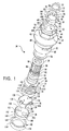
- a valve assembly 20 includes a housing or bonnet 22 and a stem 24, both of which are composed of a copper alloy such as, for example, brass.
- the valve assembly 20 further includes a thrust washer 26, an O-ring 28, a reversible stop 30, which is composed of stainless steel, and a retainer 32, composed of a resilient material such as, for example, rubber.
- the housing 22 is formed with a lower cylindrical section 42, a threaded section 44, an intermediate flared section 46, a hexagonal section 48 and an upper cylindrical section 50.
- the housing 22 is formed with a bore 52 which extends axially therethrough from a lower opening 54 to an upper opening 56.
- a first shoulder 58 is formed in the bore 52 near the opening 54 and a second shoulder 60 is formed in an intermediate portion of the bore.
- An end surface 62 is formed on the housing 22 and surrounds the upper opening 56 of the bore 52.
- a pair of opposed stop tabs 64 having stop surfaces 66 are formed with and extend in an axial direction from the end surface 52.
- a pair of fluid-flow windows 68 are formed through opposed portions of the lower cylindrical section 42 immediately below the threaded section 44.
- a first slot 70 is formed within the bore 52 and extends in an axial direction between the shoulder 58 and the adjacent window 68.
- a second slot 72 is formed within the bore 52 at a location opposite the slot 70 and also extends between in an axial direction between the shoulder 58 and the adjacent window 68.
- the slot 70 is formed with a prescribed width which is centred about a horizontal centreline as viewed in Figure 6.
- the slot 72 is wider than the slot 70 but is offset somewhat from the horizontal centreline as viewed in Figure 6. As shown, the portions of both of the slots 70 and 72 above the horizontal centreline extend an equal distance. However, the portion of the slot 72 below the centreline extends considerably more from the centreline than the comparable portion of the slot 70.
- the stem 24 is formed with a shank portion 74 and a disc-like base 76 integrally joined to the lower end of the shank portion.
- the base 76 is formed with an upper surface 77 which is contiguous with the shank portion 74.
- An annular groove 78 is formed about an intermediate section of the shank portion 74 for eventual receipt of the O-ring 28.
- the upper end of the shank portion is formed with a first set of splines 80 and a second set of splines 82 spaced from the first set by an annular groove 84.
- the splines 80 and 82 extend in an axial direction and are aligned with each other.
- a space 86 is formed in the first set of splines 80 in an area which would normally be occupied by one of the splines.
- a space 88 is formed in the second set of splines 82 in an area normally occupied by one of the splines.
- the spaces 86 and 88 are aligned as shown in Figure 1.
- a drive bar 90 is formed diametrically and nearly fully across the underside of the base 76 of the stem 24.
- the drive bar 90 is elongated and slender and is formed with four essentially squared corners.
- the reversible stop 30 is formed in a disc-like, flat configuration having a pair of ears 92 extending radially outward from opposite sides of a circular body 94.
- the stop 30 is formed with a large axial opening 96 through the body 94 with a series of juxtaposed spaces 98 arranged radially on the inside of the opening.
- Each of the spaces 98 is shaped in a configuration essentially the same as the configuration of each of the splines 80 and 82 of the stem 24.
- a plurality of radially inward projections 99 are formed between adjacent spaces 98 and are the most radially inboard portions of the stop 30.
- a wide spline 100 is formed on the inside of the opening 96 of the stop 30 in radial arrangement with the spaces 98 and is shaped in essentially the same configuration as the space 86 of the stem 24.
- the ears 92 are each formed with a pair of stop surfaces 102.
- a first flat major surface 104 of the stop 30 is formed without any interruptions while a second flat major surface 106, on a side of the stop opposite the first major surface, is formed with two "V" shaped grooves 108 which are aligned and on opposite sides of the opening 96.
- the retainer 32 is formed in a circular configuration and is composed of a compliant material such as, for example, silicone.
- the retainer 32 is formed with a rectangular cross section as shown in Figures 3 and 4,
- the coupler 34 is formed generally in a circular configuration.
- the coupler 34 is composed of a plastic material such as, for example, a thermoplastic material available from DuPont under the trademark "Delrin.”
- a plastic material such as, for example, a thermoplastic material available from DuPont under the trademark "Delrin.”
- On a first major surface 110 of the coupler 34 four pie-shaped cutouts 112 are formed in a four-quadrant arrangement and an elongated, slender slot 114 is formed diametrically nearly fully across the surface.
- the slot is configured somewhat as a complementary configuration to the configuration of the drive bar 90.
- four corners 115 of the elongated slot 114 are formed with the thermoplastic material of the coupler 34 to the extent that the corners are rounded from the top of the slot to the base thereof. In this respect, the four corners 115 of the slot 114 differ from the squared corners of the drive bar 90.
- the coupler 34 is formed with a second major surface 116 having a pair of diametrically spaced, cube-like blocks 118 extending outward from opposite edges of the side.
- a pair of diametrically-spaced guide members 120 are also formed on the second major surface 116 and extend outward from opposite edges of the surface.
- the guide members 120 are each formed with a flat surface 122 which interfaces with the flat surface of the other guide member and which are parallel with each other and with the alignment of the blocks 118.
- a plurality of crush ribs 123 are formed on the flat surfaces 122 of the guide members 120 and on the interfacing surfaces of the blocks 118 as an integral portion of the coupler 34.
- the rotatable disc 36 is formed with a flat upper surface 124 with convex end surfaces 126 and spaced, parallel, straight side edges 128.
- a pair of notches 130 are formed centrally in each of the convex end surfaces 126 and the flat upper surface 124.
- the rotatable disc 36 is formed with a flat bottom surface 132 having convex end edges 136 which are contiguous with the convex end surfaces 126.
- a pair of "V" shaped spaces 138 are formed on opposite sides of the rotatable disc 36 and are contiguous with the straight side edges 128.
- the spaces 138 form a pair rectangular openings on opposite sides of the disc 36 and a pair of "V" shaped opening at the bottom of the disc.
- a series of step surfaces 140 are formed in a ceiling of each of the spaces 138 as shown in Figs. 3, 4 and 9.
- the fixed disc 38 is formed with a flat upper surface 142 and a circular side 144. As shown in Figure 10, the disc 38 is formed with a flat bottom surface 146. As shown in Figures 1 and 10, a first ear 148 and a second ear 150 extend radially outward from opposite portions of the side 144 of the disc 38. The first ear 148 is located symmetrically about a centreline as viewed in Figure 10 while the second ear 150 has a portion which offset to the right of the centreline. A pair of pie-shaped openings 152 are formed through the disc 36.
- the bottom seal 40 is formed in a circular configuration with a circular groove 154 formed centrally in each side of the seal.
- Each of the grooves 154 of the seal 40 is formed with spaced sidewalls 156 and a base 158 which extends between the sidewalls and which faces outward of the seal.
- the formation of each groove 154 in the seal 40 results in an outward facing surface 160 on an outboard side of the groove and an outward surface 162 on an inboard side of the groove.
- the surfaces 160 and 162 are separated by the groove 154 and the surfaces 158, 160 and 162 all face in an outward direction with respect to the seal 40.
- the seal 40 is formed with an axial opening 164.
- the thrust washer 26 is positioned over the shank portion 74 of the stem 24 and is located on the upper surface of the base 76.
- the O-ring 28 is placed over the shank portion 74 of the stem 24 and is compliantly located in the annular groove 78 formed in the shank portion.
- the rotatable disc 36 is then assembled with the coupler 34 by aligning the blocks 118 of the coupler with the notches 130 of the disc. Thereafter, the coupler 34 and the disc 36 are moved relatively toward each other so that the blocks 118 move into the notches 130 and the straight side edges 128 of the disc are guided between the guide members 120 of the coupler.
- the surface 116 of the coupler 34 is placed in interfacing engagement with the surface 124 of the disc 36.
- the edges of the disc engage and deform, and essentially crush, the crush ribs 123 to the extent that the disc and the coupler fit snugly together. This facilitates and provides a tight fit between the coupler 34 and the rotatable disc 36 and precludes the tendency for lost motion between the coupler and the disc between the driving rotation of the coupler and the driven rotation of the disc.
- the stem 24 is then manipulated to align, and assemble, the drive bar 90 thereof with the elongated slot 114 of the coupler 34.
- the metal material at the four squared corners of the bar engages and deforms, and essentially crushes, the thermoplastic material of the curved corners 115 to the extent that the bar fits snugly into the slot. This facilitates and provides a relatively tight fit between the bar 90 and the slot 114 and precludes the tendency for lost motion between the driving rotation of the stem 24 and the driven rotation of the coupler 34.
- a lubricating grease is applied to the shank portion 74 of the stem 24 between, and on either side of, the thrust washer 26 and the O-ring 28. Also, grease is applied in the area of the junctures of the bottom of the stem 24 and the top of the coupler 34, the bottom of the coupler and the top of the rotatable disc 36, and the disc 36 and the fixed disc 38.
- the shank portion 74 of the stem 24 is then inserted into the bore 52 of the housing 22 through lower opening 54 thereof and is moved into the bore so that the upper end of the shank portion extends outward from the upper opening 56 of the bore as shown in Figures 3 and 4.
- the stem 24 is not moved fully to its final position within the housing 22 at this time.
- the fixed disc 38 is positioned with the upper surface 142 thereof facing the bottom surface 132 of disc 36 and with ears 148 and 150 thereof aligned with slots 70 and 72, respectively, of housing 22. It is noted that, due to the offset configuration of the ear 150, and the corresponding offset configuration of the slot 72, the fixed disc 38 can be inserted into assembly with housing 22 only in one orientation. This feature insures that the fixed disc 38 is always assembled with the rotatable disc 36 in the proper relationship for operation of the valve assembly 20.
- the fixed disc 38 is then moved into a position where the bottom surface 132 of disc 36 is in interfacing engagement with the top surface 142 of the fixed disc.
- the assembly of the stem 24, the coupler 34 and the rotatable disc 36 remain partially positioned within the housing 22 to provide a back wall against which the fixed disc can be properly aligned within the housing as the ears 148 and 150 are being inserted into the slots 70 and 72, respectively.
- the fixed disc 38 is pushed further into the housing 22 whereby the stem 24, the coupler 34 and the rotatable disc 36 are fully seated in their final position within the housing.
- the thrust washer 26 is sandwiched between the upper surface 77 of the stem 24 and the shoulder 60 of the housing 22. Also, the splines 80 and 82 of the stem 24 extend fully outward from opening 56 of the housing 22 in their final position.
- the bottom seal 40 is then assembled within the opening 54 of the housing 22 and is pressed into engagement with the bottom surface 146 of the fixed disc 38. Lower portions of the seal 40 extend outward from the opening 54 for subsequent sealing engagement with a seat in an end body (not shown) associated with the faucet.
- the outer diameter of the seal 40 is slightly larger than the diameter of opening 54 of the housing 22 whereby the seal is frictionally held within the opening. This provides an assist in retaining the assembled stem 24, coupler 34, rotatable disc 36 and the fixed disc 38 within the housing.
- a seal used for this purpose was composed of a silicone rubber, a soft material which deflects easily but is relatively expensive.
- a seal such as the seal 40, could be composed of an EPDM rubber which is less costly and is sufficiently resistant to the chemicals of the water passing therethrough.
- EPDM rubber is harder and stiffer than silicone rubber and requires greater force for deflecting a given volume. If the full interfacing surface of a seal composed of EPDM rubber was placed in engagement with the fixed disc 38, the turning of the stem 24 by the user of the associated faucet would be difficult due to the area of frictional contact between the seal and the fixed disc, the spring constant of the material and the composition of the material.
- annular groove 154 By forming the annular groove 154 in the seal 40, only the areas of surfaces 160 and 162 engage the bottom surface 146 of the fixed disc 38 which provides a watertight seal and sufficient frictional contact to allow for easy turning of the stem 24 and disc 36 during use of the associated faucet. With this arrangement, there is less comparable material to deflect and thereby less force is required. Also, it is noted that the spaced surfaces 160 and 162 and the surface of the base 158 interface with the bottom surface 146 of the fixed disc 38. However, only the spaced surfaces 160 and 162 of the seal 40 apply a prescribed force against the bottom surface 146 of the disc 38 to allow the turning of the stem 24 and disc 36 while the seal continues to assist in retaining the assembled components within the housing 22.
- the compliant retainer 32 is then stretched as it is moved over the first set of splines 80 and is compliantly placed into the annular groove 84. In this position, the radially outer portions of the retainer 32 occupy an area directly above an area which eventually will be occupied by the radially inward projections 99 of the stop 30.
- the reversible stop 30 is then positioned over the upper end of the shank portion 74 of the stem 24 and is oriented so that the wide spline 100 thereof is located in alignment with the wide space 86 of the shank portion. In this position, the spaces 98 of the stop 30 are aligned with the first set of splines 80 formed at the upper end of the shank portion 74.
- the stop 30 is then moved over the first set of splines 80, past the retainer 32 previously assembled in the annular groove 84 and onto the second set of splines 82 whereby the wide spline 100 of the stop is located within the wide space 88 formed on the shank portion adjacent the second set of splines.
- the radially outward portions of the retainer are compressed momentarily by the radially inward projections 99 of the stop to allow the stop to be assembled onto the splines 82.
- the radially outward portions of the retainer decompress and extend over the radially inward projections 99 of the stop which thereby prevents the stop from unintentionally moving outward of the stem 24 from its mounted position on the splines 82. If it is necessary to remove the stop 30, the reverse procedure is effected.
- the retainer 32 as described above, the stop 30 can be easily and quickly removed without any special tooling and without dismantling any other components of the valve assembly 20.
- the reversible stop 30 must be removed and manipulated to accommodate the lever handle convention in accordance with certain principles of the invention.
- Other conventions could be used with the round or cross handles, and with the lever handles, which could utilise the reversible stop 30 as described and claimed herein without departing from the spirit and scope of the invention.
- valve assembly 20 is to be assembled with a two-handle faucet using round or cross handles for controlling both the hot water side and the cold water side
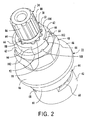
- the stop 30 is assembled as shown in Figures 2 and 11 with the plain-side surface 104 facing up and the ears 92 being located to the clockwise right of the tabs 64.
- the illustrations of Figures 2 and 11 depict an open valve whereby the spaces 138 of the rotatable disc 36 are aligned with the pie-shaped openings 152 of the fixed disc 38. Water will flow through the opening 164 of the seal 40, through the openings 152 of the fixed disc 38, through the spaces 138 of the rotatable disc 36 and through the windows 68 formed in the housing 22.
- the valve When the stem 24 is turned clockwise to the extent permitted by the tabs 64 and ears 92, the valve will be closed whereby the spaces 138 of the rotatable disc 36 are moved so that no portions of the spaces overlap with any portions of the pie-shaped openings 152 of the fixed disc 38. It is noted that the extreme limit positions for turning the valve from fully closed to fully open allows the stem 24 and rotatable disc 36 to be turned approximately one quarter of a full revolution.
- an installer removes the round or cross handle from atop the stem 24 of the hot water valve assembly 20 and replaces the handle with a lever handle.
- the round or cross handle is removed by the installer from atop the stem 24 to expose the reversible stop 30.
- the stop 30 is then gripped by the installer and easily removed as described above without the use of any tools and without removing any other component of the valve assembly 20.
- the installer then flips the stop 30 over so that the surface 106 is facing upward and the wide spline 100 of the stop is in alignment with wide spaces 86 and 88 of the stem 24.
- the stop 30 is then reinserted onto the splines 80, biasingly past the retainer 32 and onto the splines 82 whereby the ears 92 are located to the counterclockwise left of the tabs 64 as viewed in Figures 12 and 13.
- the position of the stop 30 in Figures 12 and 13 represent a fully open valve. By turning the stem 24 in a counterclockwise direction as viewed in Figures 12 and 13, the valve will be closed.
- the grooves 108 will appear and, when the stop is reinserted, will provide indication that the components of the valve assembly 20 have been assembled in an orientation to be used as a cold water valve with a lever handle under the convention described above.
- the stop 30 could be assembled initially at the factory for use with a lever handle where the upwardly facing grooves 108 provide indication to the factory people of the intended use as well as providing indication to the ultimate on-site installer of the faucet.
- This feature is also an advantage to the do-it-yourselfer who installs and completes such conversion projects without the need for professional assistance. Further, plumbers and installers who are working on tract projects involving multiple houses have a limited time in which to accomplish plumbing installations.
- the indicating feature of the stop 30 and the ease of removal and reversal thereof without the need for any tooling or dismantling other components of the valve assembly 20 provide the opportunity for the replacement and/or installation process to be accomplished in relatively short periods of time.
- the premise of providing an indicating structure, such as, for example, the grooves 108, on one side of the stop 30 could be used with other valve-turning-direction conventions for turning the valves of a two handle faucet.
Landscapes
- Engineering & Computer Science (AREA)
- General Engineering & Computer Science (AREA)
- Mechanical Engineering (AREA)
- Multiple-Way Valves (AREA)
- Sliding Valves (AREA)
- Valve Housings (AREA)
- Taps Or Cocks (AREA)
Abstract
Description
- The present invention relates to a valve assembly and, in particular, to a non-rise valve assembly.
- Faucets which are typically used in a lavatory or a kitchen may use a valve with a single-handle control or a two-handle control. In a two-handle valving arrangement, the valves are located on each side of a spout of the faucet and are referred to as the left side valve, for controlling the supply of hot water, and the right side valve for controlling the supply of cold water. For many years, and to the present, one type of two-handle valve which has been in use includes a stem which is threadedly mounted in a bonnet. When either of the handles of the faucet is turned to open the respective valve, the stem is threadedly operated and thereby rises from its closed position because of its threaded mounting to separate a compliant washer from its closed seat to thereby allow water to flow past the seat and eventually from the spout.
- Another type of valve used in a two-handle faucet is a non-rise valve and employs two ceramic discs which are always in interfacing engagement and which are formed with openings to facilitate the flow of water therethrough. When the openings of the discs are not aligned in any respect, the valve is closed to prevent the flow of water therethrough. When the valve handle and associated stem are turned, one of the discs which is attached to the stem is rotated relative to the other disc while the two discs remain in interfacing engagement. Eventually, the openings of the discs are aligned and water is allowed to flow through the openings and out of the spout. In this type of valve, the stem of the valve does not rise as the valve is opened, in contrast to the valve with the threadedly mounted stem noted above. A few examples of the many valves of the ceramic type are disclosed in U.S. Patents Nos. 3,780,758; 3,831,621 and 5,174,324.
- Generally , in ceramic valves of this type, the stem is freely rotatable within the bonnet in a clockwise direction and a counterclockwise direction. Therefore, a given design of a ceramic valve could be used on both sides of a two-handle faucet, that is as a right side valve and as a left side valve to provide the turning direction typically associated with a cold water valve on the right side of the faucet and a hot water valve on the left side of the faucet. However, a turning limit stop must be employed to limit the turning of the valve in each direction to one-quarter of a full turn. In order to take advantage of the possibility of using ceramic valves of a common design on both sides of the faucet, a reversible stop is used with each valve to limit the turning of the stem in one direction or the other depending on whether the valve is being used on the right side or the left side of the faucet. An example of a reversible stop which is used for this purpose is disclosed in U.S. Patent No. 3,831,621.
- When assembling the components of a ceramic valve of the type noted above, it is critical that the components be assembled in the proper relationship and orientation, otherwise the valve will not function in the manner intended. Typically, the components of the valves are assembled in a factory to form the valves. During the assembly process, the reversible stops are assembled so that each valve is either a hot water or a cold water valve and the valves are segregated accordingly. A hot water valve is then assembled into one of a pair of spaced end bodies on opposite ends of an underbody which is to the left of a centre body thereof. A cold water valve is then assembled into the other end body which is to the right of the centre body. The underbody is then assembled with other elements to form a faucet. The faucet is packaged and shipped, eventually, to an installation site where it is installed in a plumbing system. Thus, it is important that some provision be made to insure that the reversible stop is assembled in the proper manner to provide a hot water or a cold water valve so that, when that valve is assembled with the underbody, it is assembled in the appropriate end body thereof.
- During the period immediately following the assembly of the components of the valve, the valve is transported within the factory to various stations for further processing. Also, individual valves may be packaged and sold as replacement units for installation with existing, previously installed faucets.
- Current techniques and facilities for retaining the assembled reversible stop with the valve assembly, typically include elements which require tools to insert and remove the stop. This requires that the installer carry appropriate tools necessary for such actions. In the factory as well as at the installation site, provision must be made for retaining the reversible stop of the valve in assembly during periods of handling, shipment, storage, and ultimate assembly with other elements of a faucet at the factory or installation sites. In addition, provision must be made for facilitating easy removal of the stop.
- With respect to the valves which are installed as replacements in existing faucets, provision must be made to ensure that, when replacing a hot water valve or a cold water valve, the reversible stop is assembled in the appropriate manner for the valve to function accordingly. Of course, the same provision must be made to ensure the appropriate assembly in the factory.
- Currently, a bottom seal element is assembled at the bottom of two-handle valve assemblies of the type described above. The bottom seal must be composed of a material which provides a water-tight seal at the bottom of the valve assembly while placing a limited stress on valving components which allow the valve assembly to be operated with relative and comfortable ease. The bottom seals currently used include a compliant member which is composed of a relatively expensive material. Thus, it is important that provision be made for providing an effective bottom seal which is relatively inexpensive.
- At times, a homeowner may wish to convert a faucet from a knob-handle unit to a lever-handle unit. In this instance, only the knobs are removed and replaced by levers. When only knobs are used, the reversible stops are situated within the valve assembly in a precise manner to accommodate the conventional turning for the hot and cold water valves in the same direction, that is clockwise to close for both the hot and cold water valves. When levers are used, the hot and cold levers extend in generally opposite directions from each other when the valve is fully closed. When opening the lever-operated valves, the hot and cold valves are conventionally turned in opposite directions. For example, the cold lever is turned in a clockwise direction and the hot lever is turned in a counterclockwise direction to open the valve. Thus, to open the hot water valve for the knob assembly, the knob is turned in a counterclockwise direction, while to open the hot water valve for the lever assembly, the lever is turned in a counterclockwise direction. Therefore, provision must be made for easily reversing the hot water valve assembly when converting from a knob assembly to a lever assembly, or vice versa, and for ensuring that the reversible stop is properly oriented to accommodate such change.
- In view of the above-noted provisions, there is a need for a valve assembly which can be assembled in an efficient manner while insuring that a reversible stop thereof is properly assembled for the valve to function in the intended manner. In addition, there is a need for facilities which provide for the easy assembly and disassembly of the reversible stop. Further, there is a need for facilities which allow for the easy and comfortable operation of the valve assembly while providing necessary sealing in appropriate areas of the valve assembly.
- It is an object of the present invention to provide a valve assembly having facility for ensuring that components of the valve are assembled in an intended manner for proper operation thereof.
- It is a further object of the present invention to provide a valve assembly having facility for ensuring that components of the valve assembly may be easily assembled and disassembled.
- It is another object of the invention to provide for easy and comfortable operation of the valve assembly while providing necessary sealing in appropriate areas.
- The present invention provides a valve assembly, characterised in that it comprises a housing having a bore therethrough; a stem mounted within the bore of the housing for free rotation relative thereto; a first end of the stem extends from a first opening of the housing; a first fluid-flow valve element located within the bore of the housing and coupled to a second end of the stem for rotation therewith; a second fluid-flow valve element fixedly attached within the bore of the housing adjacent a second end of the housing; the first valve element is formed with a surface which is in facing engagement with a first surface of the second valve element;
a retainer assembled at least partially within a second opening of the housing to assist in retention of the stem, the first valve element and the second valve element within the housing; and the retainer formed with structure which interfaces with a second surface of the second valve element with only a portion of the interfacing structure in engagement with the second surface of the second valve to apply a prescribed force against the second surface of the second valve element and thereby allow the turning of the stem and the first valve element relative to the second valve element while continuing to function as the retainer. - This invention further provides a valve assembly which includes a housing and a stem mounted within the housing for free rotation relative thereto. A first end of the stem extends from a first opening of the housing and is formed with structure for supporting a reversible stop element in a complementary manner. The reversible is formed with indicating structure on one surface thereof to provide indication of the orientation of the stop. A first fluid-flow valve element is located within the housing and is coupled to a second end of the stem for rotation therewith. The first valve element is formed with a surface which is in facing engagement with a surface of a second fluid-flow valve element fixedly attached within and to the housing adjacent a second end of the housing. A retainer is assembled on the stem to preclude unintentional disassembly of the stop element from the stem.
- A valve assembly according to the invention will now be described with reference to the accompanying drawings, in which:
- Figure 1 is an exploded perspective view showing a valve assembly according to the invention;
- Figure 2 is an assembled perspective view showing the valve assembly of Figure 1;
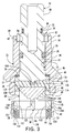
- Figure 3 is a sectional view showing structural features of the valve assembly of Figure 1;
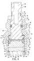
- Figure 4 is a sectional view showing structural features of the valve assembly of Figure 1;
- Figure 5 is a sectional view showing a housing or bonnet of the valve assembly of Figure 1;
- Figure 6 is a sectional view showing structural features of the housing of Figure 5;
- Figure 7 is a partial perspective view showing an end of a stem of the valve assembly of Figure 1;
- Figure 8 is a perspective view showing structural features of one side of a coupling of the valve assembly of Figure 1;
- Figure 9 is a bottom view showing a first valve element of the valve assembly of Figure 1;
- Figure 10 is a top view showing a second valve element of the valve assembly of Figure 1;
- Figure 11 is a top view of the valve assembly of Figure 2 showing a first relation between a reversible stop on the stem of Figure 7 and stop surfaces on the housing of Figure 5;
- Figure 12 is a partial perspective view of the valve assembly of Figure 1 showing a second relation between the reversible stop and the stop surfaces of Figure 11;
- Figure 13 is a top view of the valve assembly of Figure 1 showing the second relation between the reversible stop and the stop surfaces of Fig 12; and
- Figure 14 is an enlarged partial sectional view of a bottom seal.
- Referring to Figure 1, a
valve assembly 20 includes a housing orbonnet 22 and astem 24, both of which are composed of a copper alloy such as, for example, brass. Thevalve assembly 20 further includes athrust washer 26, an O-ring 28, areversible stop 30, which is composed of stainless steel, and aretainer 32, composed of a resilient material such as, for example, rubber. Acoupling 34, a rotatableceramic disc 36, a fixedceramic disc 38 and abottom seal 40, composed of an EPDM rubber, complete the components of thevalve assembly 30. - As shown in Figures 3, 4 and 5, the
housing 22 is formed with a lowercylindrical section 42, a threadedsection 44, an intermediate flaredsection 46, ahexagonal section 48 and an uppercylindrical section 50. Thehousing 22 is formed with abore 52 which extends axially therethrough from alower opening 54 to anupper opening 56. Afirst shoulder 58 is formed in thebore 52 near theopening 54 and asecond shoulder 60 is formed in an intermediate portion of the bore. Anend surface 62 is formed on thehousing 22 and surrounds theupper opening 56 of thebore 52. - A pair of
opposed stop tabs 64 having stop surfaces 66 (Figure 1) are formed with and extend in an axial direction from theend surface 52. As shown in Figures 1, 2, 3 and 5, a pair of fluid-flow windows 68 are formed through opposed portions of the lowercylindrical section 42 immediately below the threadedsection 44. Referring to Figures 5 and 6, afirst slot 70 is formed within thebore 52 and extends in an axial direction between theshoulder 58 and theadjacent window 68. Asecond slot 72 is formed within thebore 52 at a location opposite theslot 70 and also extends between in an axial direction between theshoulder 58 and theadjacent window 68. Theslot 70 is formed with a prescribed width which is centred about a horizontal centreline as viewed in Figure 6. Theslot 72 is wider than theslot 70 but is offset somewhat from the horizontal centreline as viewed in Figure 6. As shown, the portions of both of theslots slot 72 below the centreline extends considerably more from the centreline than the comparable portion of theslot 70. - As shown in Figure 1, the
stem 24 is formed with ashank portion 74 and a disc-like base 76 integrally joined to the lower end of the shank portion. Thebase 76 is formed with anupper surface 77 which is contiguous with theshank portion 74. Anannular groove 78 is formed about an intermediate section of theshank portion 74 for eventual receipt of the O-ring 28. The upper end of the shank portion is formed with a first set ofsplines 80 and a second set ofsplines 82 spaced from the first set by anannular groove 84. Thesplines space 86 is formed in the first set ofsplines 80 in an area which would normally be occupied by one of the splines. Aspace 88 is formed in the second set ofsplines 82 in an area normally occupied by one of the splines. Thespaces drive bar 90 is formed diametrically and nearly fully across the underside of thebase 76 of thestem 24. Thedrive bar 90 is elongated and slender and is formed with four essentially squared corners. Referring to Figures 1 and 2, thereversible stop 30 is formed in a disc-like, flat configuration having a pair ofears 92 extending radially outward from opposite sides of acircular body 94. Thestop 30 is formed with a largeaxial opening 96 through thebody 94 with a series of juxtaposedspaces 98 arranged radially on the inside of the opening. Each of thespaces 98 is shaped in a configuration essentially the same as the configuration of each of thesplines stem 24. A plurality of radiallyinward projections 99 are formed betweenadjacent spaces 98 and are the most radially inboard portions of thestop 30. In addition, awide spline 100 is formed on the inside of theopening 96 of thestop 30 in radial arrangement with thespaces 98 and is shaped in essentially the same configuration as thespace 86 of thestem 24. Theears 92 are each formed with a pair of stop surfaces 102. As shown in Figures 1, 2 and 11, a first flatmajor surface 104 of thestop 30 is formed without any interruptions while a second flatmajor surface 106, on a side of the stop opposite the first major surface, is formed with two "V" shapedgrooves 108 which are aligned and on opposite sides of theopening 96. Theretainer 32 is formed in a circular configuration and is composed of a compliant material such as, for example, silicone. Theretainer 32 is formed with a rectangular cross section as shown in Figures 3 and 4, - As shown in Figure 1, the
coupler 34 is formed generally in a circular configuration. Thecoupler 34 is composed of a plastic material such as, for example, a thermoplastic material available from DuPont under the trademark "Delrin." On a firstmajor surface 110 of thecoupler 34, four pie-shapedcutouts 112 are formed in a four-quadrant arrangement and an elongated,slender slot 114 is formed diametrically nearly fully across the surface. The slot is configured somewhat as a complementary configuration to the configuration of thedrive bar 90. As shown in Figure 1, fourcorners 115 of theelongated slot 114 are formed with the thermoplastic material of thecoupler 34 to the extent that the corners are rounded from the top of the slot to the base thereof. In this respect, the fourcorners 115 of theslot 114 differ from the squared corners of thedrive bar 90. - Referring to Figure 8, the
coupler 34 is formed with a secondmajor surface 116 having a pair of diametrically spaced, cube-like blocks 118 extending outward from opposite edges of the side. A pair of diametrically-spacedguide members 120 are also formed on the secondmajor surface 116 and extend outward from opposite edges of the surface. Theguide members 120 are each formed with aflat surface 122 which interfaces with the flat surface of the other guide member and which are parallel with each other and with the alignment of theblocks 118. As shown in Figure 8, a plurality ofcrush ribs 123 are formed on theflat surfaces 122 of theguide members 120 and on the interfacing surfaces of theblocks 118 as an integral portion of thecoupler 34. - As shown in Figure 1, the
rotatable disc 36 is formed with a flatupper surface 124 with convex end surfaces 126 and spaced, parallel, straight side edges 128. A pair ofnotches 130 are formed centrally in each of the convex end surfaces 126 and the flatupper surface 124. Referring to Figure 9, therotatable disc 36 is formed with aflat bottom surface 132 having convex end edges 136 which are contiguous with the convex end surfaces 126. A pair of "V" shapedspaces 138 are formed on opposite sides of therotatable disc 36 and are contiguous with the straight side edges 128. Thespaces 138 form a pair rectangular openings on opposite sides of thedisc 36 and a pair of "V" shaped opening at the bottom of the disc. A series of step surfaces 140 are formed in a ceiling of each of thespaces 138 as shown in Figs. 3, 4 and 9. - Referring again to Figure 1, the fixed
disc 38 is formed with a flatupper surface 142 and acircular side 144. As shown in Figure 10, thedisc 38 is formed with aflat bottom surface 146. As shown in Figures 1 and 10, afirst ear 148 and asecond ear 150 extend radially outward from opposite portions of theside 144 of thedisc 38. Thefirst ear 148 is located symmetrically about a centreline as viewed in Figure 10 while thesecond ear 150 has a portion which offset to the right of the centreline. A pair of pie-shapedopenings 152 are formed through thedisc 36. - As shown in Figures 1, 3, 4 and 14, the
bottom seal 40 is formed in a circular configuration with acircular groove 154 formed centrally in each side of the seal. Each of thegrooves 154 of theseal 40 is formed with spacedsidewalls 156 and a base 158 which extends between the sidewalls and which faces outward of the seal. The formation of eachgroove 154 in theseal 40 results in an outward facingsurface 160 on an outboard side of the groove and anoutward surface 162 on an inboard side of the groove. Thus, thesurfaces groove 154 and thesurfaces seal 40. Theseal 40 is formed with anaxial opening 164. - In the assembly of the components of the
valve assembly 20 as viewed in Figures 3 and 4, thethrust washer 26 is positioned over theshank portion 74 of thestem 24 and is located on the upper surface of thebase 76. The O-ring 28 is placed over theshank portion 74 of thestem 24 and is compliantly located in theannular groove 78 formed in the shank portion. Therotatable disc 36 is then assembled with thecoupler 34 by aligning theblocks 118 of the coupler with thenotches 130 of the disc. Thereafter, thecoupler 34 and thedisc 36 are moved relatively toward each other so that theblocks 118 move into thenotches 130 and the straight side edges 128 of the disc are guided between theguide members 120 of the coupler. Eventually, thesurface 116 of thecoupler 34 is placed in interfacing engagement with thesurface 124 of thedisc 36. As the straight side edges 128 of the rotatableceramic disc 36 are moved past theflat surfaces 122 of thecoupler 34, the edges of the disc engage and deform, and essentially crush, thecrush ribs 123 to the extent that the disc and the coupler fit snugly together. This facilitates and provides a tight fit between thecoupler 34 and therotatable disc 36 and precludes the tendency for lost motion between the coupler and the disc between the driving rotation of the coupler and the driven rotation of the disc. - The
stem 24 is then manipulated to align, and assemble, thedrive bar 90 thereof with theelongated slot 114 of thecoupler 34. As thedrive bar 90 is inserted into theslot 114, the metal material at the four squared corners of the bar engages and deforms, and essentially crushes, the thermoplastic material of thecurved corners 115 to the extent that the bar fits snugly into the slot. This facilitates and provides a relatively tight fit between thebar 90 and theslot 114 and precludes the tendency for lost motion between the driving rotation of thestem 24 and the driven rotation of thecoupler 34. - With the relatively tight fit between the
bar 90 of thestem 24 and theslot 114 of thecoupler 34, and between the coupler and therotatable disc 36, as described above, there is essentially no opportunity for any lost motion in the use of thevalve assembly 20. This provides a comfortable and assuring responsive feeling to the user of thevalve assembly 30. - A lubricating grease is applied to the
shank portion 74 of thestem 24 between, and on either side of, thethrust washer 26 and the O-ring 28. Also, grease is applied in the area of the junctures of the bottom of thestem 24 and the top of thecoupler 34, the bottom of the coupler and the top of therotatable disc 36, and thedisc 36 and the fixeddisc 38. - The
shank portion 74 of thestem 24 is then inserted into thebore 52 of thehousing 22 throughlower opening 54 thereof and is moved into the bore so that the upper end of the shank portion extends outward from theupper opening 56 of the bore as shown in Figures 3 and 4. However, thestem 24 is not moved fully to its final position within thehousing 22 at this time. Thereafter, the fixeddisc 38 is positioned with theupper surface 142 thereof facing thebottom surface 132 ofdisc 36 and withears slots housing 22. It is noted that, due to the offset configuration of theear 150, and the corresponding offset configuration of theslot 72, the fixeddisc 38 can be inserted into assembly withhousing 22 only in one orientation. This feature insures that the fixeddisc 38 is always assembled with therotatable disc 36 in the proper relationship for operation of thevalve assembly 20. - The fixed
disc 38 is then moved into a position where thebottom surface 132 ofdisc 36 is in interfacing engagement with thetop surface 142 of the fixed disc. During the period when the fixeddisc 38 is being assembled as noted above, the assembly of thestem 24, thecoupler 34 and therotatable disc 36 remain partially positioned within thehousing 22 to provide a back wall against which the fixed disc can be properly aligned within the housing as theears slots - Thereafter, the fixed
disc 38 is pushed further into thehousing 22 whereby thestem 24, thecoupler 34 and therotatable disc 36 are fully seated in their final position within the housing. In this assembly, thethrust washer 26 is sandwiched between theupper surface 77 of thestem 24 and theshoulder 60 of thehousing 22. Also, thesplines stem 24 extend fully outward from opening 56 of thehousing 22 in their final position. - The
bottom seal 40 is then assembled within theopening 54 of thehousing 22 and is pressed into engagement with thebottom surface 146 of the fixeddisc 38. Lower portions of theseal 40 extend outward from theopening 54 for subsequent sealing engagement with a seat in an end body (not shown) associated with the faucet. The outer diameter of theseal 40 is slightly larger than the diameter of opening 54 of thehousing 22 whereby the seal is frictionally held within the opening. This provides an assist in retaining the assembledstem 24,coupler 34,rotatable disc 36 and the fixeddisc 38 within the housing. In the past, a seal used for this purpose was composed of a silicone rubber, a soft material which deflects easily but is relatively expensive. In an effort to design a replacement seal for the seal composed of silicone rubber, it was determined that a seal, such as theseal 40, could be composed of an EPDM rubber which is less costly and is sufficiently resistant to the chemicals of the water passing therethrough. However, EPDM rubber is harder and stiffer than silicone rubber and requires greater force for deflecting a given volume. If the full interfacing surface of a seal composed of EPDM rubber was placed in engagement with the fixeddisc 38, the turning of thestem 24 by the user of the associated faucet would be difficult due to the area of frictional contact between the seal and the fixed disc, the spring constant of the material and the composition of the material. - By forming the
annular groove 154 in theseal 40, only the areas ofsurfaces bottom surface 146 of the fixeddisc 38 which provides a watertight seal and sufficient frictional contact to allow for easy turning of thestem 24 anddisc 36 during use of the associated faucet. With this arrangement, there is less comparable material to deflect and thereby less force is required. Also, it is noted that the spacedsurfaces bottom surface 146 of the fixeddisc 38. However, only the spacedsurfaces seal 40 apply a prescribed force against thebottom surface 146 of thedisc 38 to allow the turning of thestem 24 anddisc 36 while the seal continues to assist in retaining the assembled components within thehousing 22. - The
compliant retainer 32 is then stretched as it is moved over the first set ofsplines 80 and is compliantly placed into theannular groove 84. In this position, the radially outer portions of theretainer 32 occupy an area directly above an area which eventually will be occupied by the radiallyinward projections 99 of thestop 30. - The
reversible stop 30 is then positioned over the upper end of theshank portion 74 of thestem 24 and is oriented so that thewide spline 100 thereof is located in alignment with thewide space 86 of the shank portion. In this position, thespaces 98 of thestop 30 are aligned with the first set ofsplines 80 formed at the upper end of theshank portion 74. Thestop 30 is then moved over the first set ofsplines 80, past theretainer 32 previously assembled in theannular groove 84 and onto the second set ofsplines 82 whereby thewide spline 100 of the stop is located within thewide space 88 formed on the shank portion adjacent the second set of splines. - As the
stop 30 is moved past theretainer 32, the radially outward portions of the retainer are compressed momentarily by the radiallyinward projections 99 of the stop to allow the stop to be assembled onto thesplines 82. Once thestop 30 has been moved past theretainer 32, the radially outward portions of the retainer decompress and extend over the radiallyinward projections 99 of the stop which thereby prevents the stop from unintentionally moving outward of thestem 24 from its mounted position on thesplines 82. If it is necessary to remove thestop 30, the reverse procedure is effected. By use of theretainer 32 as described above, thestop 30 can be easily and quickly removed without any special tooling and without dismantling any other components of thevalve assembly 20. - In the past, and currently, manufacturers of two-handle faucets adopt a turning convention for the direction in which the respective valves are to be turned to open and close the hot water and cold water valves. For example, in one convention, when round knob-like handles or cross handles are used, both the hot water valve and the cold water valve are turned counterclockwise to open the valves and clockwise to close the valves. If a faucet employing the round or cross handles is to be converted to a lever handle faucet, the hot water valve will continue to use the convention noted above with respect to the round or cross handles. However, the cold water valve must now be turned clockwise to open the valve and counterclockwise to close the valve. Therefore, the
reversible stop 30 must be removed and manipulated to accommodate the lever handle convention in accordance with certain principles of the invention. Other conventions could be used with the round or cross handles, and with the lever handles, which could utilise thereversible stop 30 as described and claimed herein without departing from the spirit and scope of the invention. - If the
valve assembly 20 is to be assembled with a two-handle faucet using round or cross handles for controlling both the hot water side and the cold water side, thestop 30 is assembled as shown in Figures 2 and 11 with the plain-side surface 104 facing up and theears 92 being located to the clockwise right of thetabs 64. In this arrangement, the illustrations of Figures 2 and 11 depict an open valve whereby thespaces 138 of therotatable disc 36 are aligned with the pie-shapedopenings 152 of the fixeddisc 38. Water will flow through theopening 164 of theseal 40, through theopenings 152 of the fixeddisc 38, through thespaces 138 of therotatable disc 36 and through thewindows 68 formed in thehousing 22. When thestem 24 is turned clockwise to the extent permitted by thetabs 64 andears 92, the valve will be closed whereby thespaces 138 of therotatable disc 36 are moved so that no portions of the spaces overlap with any portions of the pie-shapedopenings 152 of the fixeddisc 38. It is noted that the extreme limit positions for turning the valve from fully closed to fully open allows thestem 24 androtatable disc 36 to be turned approximately one quarter of a full revolution. - When the faucet described above is to be converted from a round handle or a cross handle to a lever handle, an installer removes the round or cross handle from atop the
stem 24 of the hotwater valve assembly 20 and replaces the handle with a lever handle. With respect to the coldwater valve assembly 20, the round or cross handle is removed by the installer from atop thestem 24 to expose thereversible stop 30. Thestop 30 is then gripped by the installer and easily removed as described above without the use of any tools and without removing any other component of thevalve assembly 20. The installer then flips thestop 30 over so that thesurface 106 is facing upward and thewide spline 100 of the stop is in alignment withwide spaces stem 24. Thestop 30 is then reinserted onto thesplines 80, biasingly past theretainer 32 and onto thesplines 82 whereby theears 92 are located to the counterclockwise left of thetabs 64 as viewed in Figures 12 and 13. The position of thestop 30 in Figures 12 and 13 represent a fully open valve. By turning thestem 24 in a counterclockwise direction as viewed in Figures 12 and 13, the valve will be closed. - When the
stop 30 is flipped over as described above, thegrooves 108 will appear and, when the stop is reinserted, will provide indication that the components of thevalve assembly 20 have been assembled in an orientation to be used as a cold water valve with a lever handle under the convention described above. Of course, thestop 30 could be assembled initially at the factory for use with a lever handle where the upwardly facinggrooves 108 provide indication to the factory people of the intended use as well as providing indication to the ultimate on-site installer of the faucet. This feature is also an advantage to the do-it-yourselfer who installs and completes such conversion projects without the need for professional assistance. Further, plumbers and installers who are working on tract projects involving multiple houses have a limited time in which to accomplish plumbing installations. The indicating feature of thestop 30 and the ease of removal and reversal thereof without the need for any tooling or dismantling other components of thevalve assembly 20 provide the opportunity for the replacement and/or installation process to be accomplished in relatively short periods of time. - As noted above, the premise of providing an indicating structure, such as, for example, the
grooves 108, on one side of thestop 30 could be used with other valve-turning-direction conventions for turning the valves of a two handle faucet.
Claims (24)
- A valve assembly (20), characterised in that it comprises:a housing (22) having a bore (52) therethrough;a stem (24) mounted within the bore (52) of the housing (22) for free rotation relative thereto;a first end of the stem extends from a first opening (56) of the housing (22);a first fluid-flow valve element (36) located within the bore (52) of the housing (22) and coupled to a second end of the stem for rotation therewith;a second fluid-flow valve element (38) fixedly attached within the bore (52) of the housing (22) adjacent a second end of the housing;the first valve element (36) is formed with a surface (132) which is in facing engagement with a first surface (142) of the second valve element (38);a retainer (40) assembled at least partially within a second opening (54) of the housing (22) to assist in retention of the stem (24), the first valve element (36) and the second valve element (38) within the housing (22); andthe retainer (40) formed with structure (154) which interfaces with a second surface (146) of the second valve element (38) with only a portion of the interfacing structure in engagement with the second surface (146) of the second valve element (38) to apply a prescribed force against the second surface (146) of the second valve element (38) and thereby allow the turning of the stem (24) and the first valve element (36) relative to the second valve element (38) while continuing to function as the retainer.
- A valve assembly according to claim 1, characterised in that the structure of the retainer includes a first surface (160) in interfacing engagement with the second surface of the second valve element and a second surface (162) interfacing the second surface of the second valve element and spaced therefrom.
- A valve assembly according to claim 1, characterised in that the structure of the retainer comprises:a first surface (160) located in a plane and facing in a prescribed direction;a second surface (162) located in the plane and spaced from the first surface (160) and facing in the prescribed direction; anda third surface (158) located in a space between the first and second surfaces out of the plane thereof inboard of the retainer and facing in the prescribed direction.
- A valve assembly according to claim 3, characterised in that the third surface (158) is a base surface of a groove (154) formed between the first and second surfaces (160,162).
- A valve assembly according to claim 1, characterised in that the retainer (40) comprises:a compliant band having an axial opening formed therethrough and a side adjacent one end of the opening in a plane generally perpendicular an axis of the opening;a first surface (160) formed on the side and facing in a prescribed direction;a second surface (162) formed on the side and facing in the prescribed direction;a groove (154) formed between the first and second surfaces (160,162) having a base surface (158) spaced inboard of the retainer (40) from the first and second surfaces (160,162) and facing in the prescribed direction.
- A valve assembly, characterised in that it comprises:a housing (22) having a bore (52) extending therethrough;a stem (24) mounted within the bore (52) of the housing (22) for free rotation relative thereto;a reversible stop element (30) positionable in either of at least two orientations;a first end of the stem (24) extends from a first opening (56) of the housing (22) and is formed with structure for supporting the reversible stop element (30) in either of the at least two orientations;indicating structure (106) formed on one surface (106) of the reversible stop element (30) to provide indication that the reversible stop element (30) is in a particular one of the at least two orientations;a first fluid-flow valve element (36) located within the bore (52) of the housing (22) coupled to a second end of the stem for rotation therewith; anda second fluid-flow valve element (38) fixedly attached within the bore (52) of the housing (22) adjacent a second end of the housing (22).
- A valve assembly according to claim 6, characterised in that it further comprises:
a retainer (32) assembled on the stem to preclude unintentional disassembly of the reversible stop element (30) from the stem (24). - A valve assembly according to claim 6 or claim 7, characterised in that the indicating structure is a groove (108) formed in a selected portion of the one surface (106) of the reversible stop element (30).
- A valve assembly, characterised in that it comprises:a housing (22) having a bore (52) extending therethrough;a stem (24) mounted within the bore (52) of the housing (22) for free rotation relative thereto and formed with a first end which extends from a first opening (56) of the housing (22);a reversible stop element (30) positionable on the first end of the stem (24) in either of at least two orientations;a retainer (32) assembled on the first end of the stem (24) to preclude unintentional disassembly of the reversible stop element (30) from the stem (24) and being sufficiently compliant in selected portions to allow the reversible stop element (30) to be removed from the stem (24) without removing the retainer (32) from the stem (24);a first fluid-flow valve element (36) located within the bore (52) of the housing (22) and coupled to a second end of the stem (24) for rotation therewith; anda second fluid-flow valve element (38) fixedly attached within the bore (52) of the housing (22) adjacent a second end of the housing (22).
- A valve assembly according to claim 9, characterised in that it further comprises a groove formed about a portion of the stem between the first end thereof and a location of the reversible stop element (30) on the stem; andthe retainer (32) comprises:a compliant band located in the groove and having radially outboard portions extending over radially inboard portions of the reversible stop element (30).
- A valve assembly, which comprises:a housing (22) having a bore (52) therethrough;a stem (24) mounted within the bore (52) of the housing (22) for rotation relative thereto and formed with an end located within the bore (52) of the housing (22);a first fluid-flow valve element (36) located within the bore (52) of the housing (22);a coupler (34) located within the bore (52) of the housing (22) for coupling the end of the stem (24) to the first valve element (36);the stem (24) formed with a drive element (90) at the end thereof for assembly with complementary structure (114) formed on the coupler (34);structure formed on the coupler (34) adjacent the complementary structure (114) which is responsive to the assembly of the drive element (90) with the complementary structure (114) for providing a tight fit between the stem (24) and the coupler (34); anda second fluid-flow valve element (38) fixedly attached within the bore (52) of the housing adjacent a second end of the housing (22).
- A valve assembly according to in claim 11,
characterised in that the fitting structure comprises material formation located adjacent the complementary structure (114) of the coupler (34) in the path of the drive element (90) when the drive element (90) is assembled with the complementary structure (114) where the material formation is susceptible to deformation by the drive element (90). - A valve assembly according to claim 11, characterised in that the drive element (90) is shaped as a bar having four squared corners and the complementary structure (114) of the coupler is a slot (114) having four corners (115) with material formed therein in a shape other than squared corners and positioned for interference with the squared corners of the bar (90) when the bar (90) is assembled within the slot (114).
- A valve assembly according to claim 13, characterised in that the shape of the four corners (115) of the slot (114) is curved.
- A valve assembly, which comprises:a housing (22) having a bore (52) therethrough;a stem (24) mounted within the bore (52) of the housing (22) for rotation relative thereto and formed with an end within the bore (52) of the housing (22);a first fluid-flow valve element (36) located within the bore (52) of the housing (22);a coupler (34) located within, the bore (52) of the housing (22) for coupling the end of the stem (24) to the first valve element (36);the coupler (34) formed with drive structure (118) for assembly with complementary structure (130) formed on the first valve element (36);fitting structure formed on the coupler (34) adjacent to the drive structure (118) which is responsive to the assembly of the drive structure (118) with the complementary structure (130) to provide a tight fit between the coupler (34) and the first valve element (36); anda second fluid-flow valve element (38) fixedly attached within the bore (52) of the housing (22) adjacent a second end of the housing (22).
- A valve assembly according to claim 15, characterised in that the drive structure of the coupler (34) comprises:a pair of spaced blocks (118) formed on a common surface of the coupler (34), each having a surface which interfaces with the surface of the other block; andat least one rib (123) formed on the interfacing surface of each block which is located for interference with structure of the first valve element (36) upon assembly of the coupler (34) with the first valve element (36).
- A valve assembly according to claim 15, characterised in that the drive structure of the coupler (34) comprises:a pair of spaced guide members (129) formed on a common surface of the coupler (34), each having a surface which interfaces with the surface of the other guide member;at least one rib (123) formed on the interfacing surface of each guide member (120) which is located for interference with structure of the first valve element (36) upon assembly of the coupler (34) with the first valve element (36).
- A valve assembly according to claim 16, characterised in that the drive structure of the coupler (34) further comprises:a pair of spaced guide members (120) formed on the common surface of the coupler (34) in spaced relation with the blocks (118), each guide member (120) having a surface which interfaces with the surface of the other guide member;at least one rib (123) formed on the interfacing surface of each guide member (120) which is located for interference with structure of the first valve element (36) upon assembly of the coupler with the first valve element (36).
- A valve assembly according to claim 15, characterised in that it further comprises:the stem (24) formed with a drive element (90) at the end thereof for assembly with mating structure (114) formed on the coupler (34); andstructure formed on the coupler (34) adjacent the mating structure (114) which is responsive to the assembly of the drive element (90) with the mating structure (114) for providing a tight fit between the stem (24) and the coupler (34).
- A valve assembly, which comprises:a housing (22) having a bore (52) therethrough;a stem mounted within the bore (22) of the housing (52) for free rotation relative thereto;a first end of the stem (24) extends from a first opening (56) of the housing;a first fluid-flow valve element (36) located within the bore (52) of the housing (22) and coupled to a second end of the stem (24) for rotation therewith;a second fluid-flow valve element (38) fixedly attached within the bore (52) of the housing (22) adjacent a second end of the housing (22); the first valve element (36) is formed with a surface (132) which is in facing engagement with a first surface (142) of the second valve element (38);a compliant seal (40) having an axial opening therethrough assembled at least partially within a second opening of the housing; andthe compliant seal (40) formed with structure (154) which interfaces with a second surface (146) of the second valve element (38) with only a portion (160,162) of the interfacing structure in engagement with the second surface (146) of the second valve (38) to form a fluid seal at the juncture of the compliant seal (40) and the second surface (146) of the second valve element (38).
- A valve assembly, characterised in that it comprises: a housing (22) having a bore (52) therethrough;a stem mounted within the bore (52) of the housing (22) for free rotation relative thereto and having an end within the bore (52);a first fluid-flow valve element (36) located within the bore (52);a first fluid-flow valve element (36) located within the bore (52) of the housing (22) and coupled to the end of the stem (24) for rotation therewith;a second fluid-flow valve element (38) fixedly attached within the bore (52) of the housing (22) adjacent a second end of the housing (22);the second valve element (38) formed with a first structure and the housing (22) formed with a second structure within the bore (52) thereof which is complementary in configuration to the configuration of the first structure to limit the assembly of the second valve element (38) within the housing (22) to a single orientation and position.
- A valve assembly according to claim 21, characterised in that the first structure comprises:a first ear (148) formed radially outward from a first side of the second valve element (38);a second ear (150) formed radially outward from a second side of the second valve element (38) opposite the first side;the first ear (148) being formed with a first prescribed width having equal lateral portions on each side of a line passing through the first ear and the second ear; andthe second ear (150) being formed with a second prescribed width of greater dimension than the first prescribed width with a greater lateral portion of the width being on one side of the line than on the other side of the line.
- A valve assembly according to claim 21, characterised in that the second structure comprises:a first slot formed in a first side of the bore (52) of the housing (22) and facing radially inward;a second slot formed in a second side of the bore (52) of the housing (22) opposite the first side and facing radially inward;the first slot being formed with a first prescribed width having equal lateral portions on each side of a line passing through the first slot and the second slot; andthe second slot being formed with a second prescribed width of greater dimension than the first prescribed width with a greater lateral portion of the width being on one side of the line than on the other side of the line.
- A valve assembly according to claim 23, characterised in that the first structure comprises:a first ear (148) formed radially outward from a first side of the second valve element (38);a second ear (150) formed radially outward from a second side of the second valve element (38) opposite the first side;the first ear (148) being formed with a first prescribed width having equal lateral portions on each side of a line passing through the first ear and the second ear; andthe second ear (150) being formed with a second prescribed width of greater dimension than the first prescribed width with a greater lateral portion of the width being on one side of the line than on the other side of the line; andthe valve assembly further comprises:the first ear (148) of the second valve element (38) being located in the first slot of the housing (22); andthe second ear (150) of the second valve element (38) being located in the second slot of the housing (22).
Applications Claiming Priority (2)
| Application Number | Priority Date | Filing Date | Title |
|---|---|---|---|
| US546640 | 1983-10-28 | ||
| US08/546,640 US5681028A (en) | 1995-10-23 | 1995-10-23 | Valve assembly |
Publications (2)
| Publication Number | Publication Date |
|---|---|
| EP0770804A2 true EP0770804A2 (en) | 1997-05-02 |
| EP0770804A3 EP0770804A3 (en) | 1999-01-20 |
Family
ID=24181339
Family Applications (1)
| Application Number | Title | Priority Date | Filing Date |
|---|---|---|---|
| EP96306710A Withdrawn EP0770804A3 (en) | 1995-10-23 | 1996-09-16 | Rotary slide valve assembly |
Country Status (6)
| Country | Link |
|---|---|
| US (4) | US5681028A (en) |
| EP (1) | EP0770804A3 (en) |
| KR (1) | KR970021870A (en) |
| CA (1) | CA2181652C (en) |
| MX (1) | MX9601493A (en) |
| TW (1) | TW310021U (en) |
Families Citing this family (57)
| Publication number | Priority date | Publication date | Assignee | Title |
|---|---|---|---|---|
| US5681028A (en) * | 1995-10-23 | 1997-10-28 | Emhart Inc. | Valve assembly |
| IT1288719B1 (en) * | 1996-10-01 | 1998-09-24 | Gevipi Ag | BOTTOM WITH ANCHORED SEALING GASKETS, FOR ONE HYDRAULIC TAP CARTRIDGE. |
| JP3582055B2 (en) * | 1999-01-27 | 2004-10-27 | 日本サーモスタット株式会社 | Mounting structure of thermostat |
| JP3284407B2 (en) | 1999-01-27 | 2002-05-20 | 日本サーモスタット株式会社 | Cooling medium flow control method and device |
| AT408025B (en) * | 1999-07-20 | 2001-08-27 | Ideal Standard | SANITARY MIXING VALVE |
| US6123105A (en) * | 1999-08-11 | 2000-09-26 | Yang; Tsai Chen | Valve for mixing cold and hot water |
| IT1319940B1 (en) * | 2000-03-07 | 2003-11-12 | Gevipi Ag | DEVICE TO PROMOTE THE CONSTRUCTION UNIFICATION OF CARTRIDGES FOR HYDRAULIC EQUIPMENT. |
| DE20022320U1 (en) * | 2000-03-08 | 2001-07-26 | ANTON TRÄNKLE GMBH & CO KG, 78098 Triberg | Sealing device for an upper valve part, in particular for water fittings |
| US6382229B1 (en) * | 2000-12-08 | 2002-05-07 | Emhart Llc | Valve assembly and seal therefor |
| US6640390B1 (en) * | 2002-04-05 | 2003-11-04 | Hung-Lin Lai | Structure for confining a valve knob |
| KR20040040807A (en) * | 2002-11-08 | 2004-05-13 | 박숙진 | Opening and shutting cartridge for valve |
| US7007717B2 (en) * | 2003-08-01 | 2006-03-07 | Globe Union Industrial Corp. | Spindle structure for a ceramic faucet |
| US6988512B1 (en) * | 2003-10-01 | 2006-01-24 | Hsiang-Shih Wang | Valves stem structure of fluid control valve |
| US7178786B2 (en) * | 2003-11-21 | 2007-02-20 | Brass-Craft Manufacturing Company | Stem construction for rotatable valve body |
| US20050205144A1 (en) * | 2004-03-18 | 2005-09-22 | Rosas Richard L | Cartridge retrievable flow control valve |
| KR100455360B1 (en) * | 2004-05-07 | 2004-11-09 | 주식회사 한성시스코 | Drive valve for cooled and heating pipe work |
| US7134450B2 (en) * | 2005-03-07 | 2006-11-14 | Chung Cheng Faucet Co., Ltd. | Interior structure of water control valve for faucets |
| US7461669B2 (en) * | 2005-04-08 | 2008-12-09 | Masco Corporation Of Indiana | Seat keeper |
| US7331359B2 (en) * | 2005-04-19 | 2008-02-19 | Kohler Co. | Valve with bi-loading seal |
| USD653728S1 (en) * | 2006-03-27 | 2012-02-07 | Borgwarner Inc. | Valve disk |
| US7686028B2 (en) * | 2006-11-17 | 2010-03-30 | Hung-Neng Wu | Structure of straight-out controllable ceramic valve of anti-freezing faucet |
| US7967005B2 (en) * | 2007-04-13 | 2011-06-28 | Daniel Parrish | Dual fuel gas valve and gas grill |
| US8840349B2 (en) * | 2007-04-20 | 2014-09-23 | Fisher Controls International, Llc | Multi-tool adjusting screw |
| US7581685B2 (en) * | 2007-07-19 | 2009-09-01 | Christian Belisle | Faucet end piece |
| TWM324731U (en) * | 2007-08-06 | 2008-01-01 | Home Faucets Entpr Corp | Faucet |
| USD623724S1 (en) * | 2007-10-03 | 2010-09-14 | Masco Corporation Of Indiana | Single handle valve cartridge |
| US20090266431A1 (en) * | 2008-04-28 | 2009-10-29 | Kuching International Co., Ltd. | Spool with two-sided effluent |
| CN102138035B (en) * | 2008-06-20 | 2013-11-27 | 印地安纳马斯科公司 | Valve assembly for two-handle mixers |
| CA2834728C (en) | 2008-06-25 | 2016-02-16 | Masco Corporation Of Indiana | Widespread faucet |
| CA2727077C (en) | 2008-06-25 | 2013-10-01 | Masco Corporation Of Indiana | Centerset faucet with mountable spout |
| US8079382B2 (en) * | 2009-11-16 | 2011-12-20 | Cheng-Hsuan Wu | Unfreeze faucet structure |
| US20110114864A1 (en) * | 2009-11-16 | 2011-05-19 | Cheng-Hsuan Wu | Watering Control Valve |
| US9376789B2 (en) | 2011-03-08 | 2016-06-28 | As Ip Holdco, Llc | Quick connection coupling |
| US9234597B2 (en) | 2011-03-11 | 2016-01-12 | Delta Faucet Company | Flow control valve |
| US8739826B2 (en) | 2011-03-11 | 2014-06-03 | Masco Corporation Of Indiana | Centerset faucet body and method of making same |
| US10260642B2 (en) * | 2011-04-26 | 2019-04-16 | As Ip Holdco, Llc | Faucet valve cartridge |
| US9441750B2 (en) * | 2011-04-26 | 2016-09-13 | Grohe Ag | Valve cartridge |
| US20120305117A1 (en) * | 2011-06-06 | 2012-12-06 | Tsung-Min Huang | Lead-free valve of faucet and process of manufacturing same |
| US9835281B2 (en) | 2011-08-24 | 2017-12-05 | As Ip Holdco, Llc | No-tools spread faucet assembly, kits and methods |
| DE102011084837A1 (en) * | 2011-10-20 | 2013-04-25 | Hansgrohe Se | Valve cartridge for a sanitary fitting |
| US8931500B2 (en) | 2012-02-17 | 2015-01-13 | Masco Corporation Of Indiana | Two handle centerset faucet |
| USD745637S1 (en) | 2013-03-22 | 2015-12-15 | Wd Racing Oy | Valve disk |
| CN204328076U (en) * | 2014-11-25 | 2015-05-13 | 厦门建霖工业有限公司 | Water purifying valve cored structure |
| CA3025934C (en) * | 2016-06-02 | 2021-05-11 | Component Hardware Group, Inc. | Valve for a faucet assembly |
| US10753075B2 (en) * | 2016-09-26 | 2020-08-25 | Zurn Industries, Llc | Flush valve |
| US10578228B2 (en) | 2016-09-26 | 2020-03-03 | Zurn Industries, Llc | Sensing mechanism for valve operation |
| US10641410B2 (en) | 2017-02-09 | 2020-05-05 | Beijingwest Industries Co., Ltd. | Pneumatic valve for air suspension systems |
| US10385978B2 (en) | 2017-10-21 | 2019-08-20 | Hector Hernandez | Cartridge assembly for regulating flows |
| DE102018107608A1 (en) * | 2018-03-29 | 2019-10-02 | Grohe Ag | Valve cartridge for a sanitary fitting with convertible closing direction |
| EP3591267B1 (en) * | 2018-07-02 | 2020-07-22 | Flühs Drehtechnik GmbH | Upper part of a valve |
| JP7166017B2 (en) * | 2018-07-26 | 2022-11-07 | 神楽フィースト株式会社 | dispenser and cock |
| US11274761B2 (en) | 2018-09-06 | 2022-03-15 | Kohler Co. | Faucet with integrated valve |
| US20200149253A1 (en) * | 2018-11-13 | 2020-05-14 | Greatness Sanitary Industrial Co., Ltd | Rotary control structure for water valve |
| USD883444S1 (en) | 2018-12-04 | 2020-05-05 | Zurn Industries, Llc | Flush valve housing |
| US11384851B2 (en) | 2019-10-08 | 2022-07-12 | Hector Hernandez | Cartridge assembly for diverting flow |
| JP7585948B2 (en) * | 2021-04-21 | 2024-11-19 | 株式会社デンソー | Valve device |
| US12338900B2 (en) * | 2023-10-18 | 2025-06-24 | Hsiang-Shih Wang | Ceramic control valve |
Family Cites Families (44)
| Publication number | Priority date | Publication date | Assignee | Title |
|---|---|---|---|---|
| US3244120A (en) * | 1963-10-28 | 1966-04-05 | Taylor Frank | Centre beam railroad car |
| US3780758A (en) * | 1972-11-15 | 1973-12-25 | Wolverine Brass Works Ind Inc | Non-metallic cartridge valve |
| US3807455A (en) * | 1973-03-19 | 1974-04-30 | Elkay Mfg Co | Replaceable cartridge for faucets |
| US3829693A (en) * | 1973-10-03 | 1974-08-13 | Barnes Eng Co | Dual field of view intrusion detector |
| US3831621A (en) * | 1973-11-19 | 1974-08-27 | Union Brass & Metal Mfg | Rotary slide valve |
| US3913612A (en) * | 1974-12-16 | 1975-10-21 | Price Pfister Brass Mfg | Eccentric shear seal cartridge valve |
| DE3068576D1 (en) * | 1979-05-04 | 1984-08-23 | Masco Corp | Single-control mixing cock with plates made of hard material |
| US4331176A (en) * | 1980-03-03 | 1982-05-25 | American Standard Inc. | Replaceable cartridge valve assembly |
| US4397330A (en) * | 1981-08-19 | 1983-08-09 | United States Brass Corporation | Mixing valve for back to back installation |
| US4462568A (en) * | 1982-03-15 | 1984-07-31 | Xomox Corporation | Valve construction and method of making the same |
| DE3244120A1 (en) * | 1982-11-29 | 1984-05-30 | Friedrich Grohe Armaturenfabrik Gmbh & Co, 5870 Hemer | Seal or connecting seal for sanitary mixing valves |
| US4611788A (en) * | 1983-06-15 | 1986-09-16 | Bruce J. Oliver | Combination seat and seal device |
| US4823832A (en) * | 1984-07-11 | 1989-04-25 | Harden Industries, Inc. | Cartridge valve |
| US4678002A (en) * | 1985-05-10 | 1987-07-07 | Valley Harold J | Faucet valve with adjustable stem tightener |
| NZ216420A (en) * | 1985-06-13 | 1987-04-30 | Dorf Ind Pty Ltd | Replacement top for screw down tap: adjustment nut allows axial adjustment in permanent sealing of tap assembly to seat in tap body |
| US4651770A (en) * | 1986-03-28 | 1987-03-24 | Speakman Company | Ceramic disc faucet valve |
| JPH01501239A (en) * | 1986-09-12 | 1989-04-27 | フリユース ドレーテヒニク ゲゼルシヤフト ミツト ベシユレンクテル ハフツング | seal for valve |
| EP0320506B1 (en) * | 1987-06-25 | 1993-02-24 | Masco Corporation Of Indiana | A reversible bottom valve cartridge with an orienting mechanism |
| US4793375A (en) * | 1987-07-16 | 1988-12-27 | Masco Corporation Of Indiana | Faucet valve cartridge |
| DE3827469A1 (en) * | 1987-08-14 | 1989-02-23 | Dorf Ind Pty Ltd | SEALING RING FOR TAPS |
| CH673693A5 (en) * | 1987-09-11 | 1990-03-30 | Kugler Fonderie Robinetterie | |
| US4966186A (en) * | 1988-01-20 | 1990-10-30 | Harden Industries, Inc. | Cartridge valve |
| CH675759A5 (en) * | 1988-01-27 | 1990-10-31 | Karrer Weber & Cie Ag | |
| US4821765A (en) * | 1988-06-10 | 1989-04-18 | Kohler Co. | Valve for faucet or the like |
| DE3828178A1 (en) * | 1988-08-19 | 1990-02-22 | Grohe Armaturen Friedrich | SHUT-OFF AND REGULATING VALVE |
| DE3829693A1 (en) * | 1988-09-01 | 1990-03-08 | Eggenfelder Aluminiumoxyd Kera | Flow-regulating valve, in particular for sanitary fittings |
| FR2644217A1 (en) * | 1989-03-07 | 1990-09-14 | Procal | STATIC SEAL SEAL |
| US4903725A (en) * | 1989-03-30 | 1990-02-27 | Ko Hsi Chia | Faucet valve assembly having a flow buffer disk |
| GB2228985B (en) * | 1989-04-04 | 1993-07-21 | Galatron Srl | 'breech-block' tap for the supply of cold or hot water with ceramic sealing plates |
| US5050633A (en) * | 1989-06-19 | 1991-09-24 | Emhart Inc. | Fluid valve |
| JPH0386446A (en) * | 1989-08-25 | 1991-04-11 | Fanuc Ltd | Copying control device |
| US5103857A (en) * | 1989-10-18 | 1992-04-14 | Kohler Co. | Self closing valve assembly |
| US4966187A (en) * | 1989-11-07 | 1990-10-30 | Wah Men Shun | Valve body concerning the bathtub cold/hot water valve |
| IT1236011B (en) * | 1989-11-08 | 1992-12-15 | Galatron Srl | VITONE TYPE VALVE WITH SEAL WITH CERAMIC PLATES |
| IT222220Z2 (en) * | 1989-11-08 | 1995-02-01 | Galatron Srl | PAIR OF PLATES TO CONTROL THE DISPENSING OF FLUID IN VITONE TYPE VALVES |
| IT1241171B (en) * | 1990-02-13 | 1993-12-29 | Studio Tecnico Sviluppo E Ricerche S.T.S.R. S.R.L. | FIXED PLATE FOR HYDRAULIC TAP, WITH MEANS FOR THE ELIMINATION OF DEBRIS |
| US5010917A (en) * | 1990-04-02 | 1991-04-30 | Kohler Co. | Fluid control valve |
| US5174324A (en) * | 1991-01-22 | 1992-12-29 | Amerikam | Ceramic valve |
| DE4101836A1 (en) * | 1991-01-23 | 1992-07-30 | Traenkle Anton Kg | VALVE PART |
| DE4212236A1 (en) * | 1992-04-11 | 1993-10-14 | Grohe Armaturen Friedrich | Control and shut-off valve |
| US5365978A (en) * | 1992-07-27 | 1994-11-22 | Baker Hughes Incorporated | Top entry flow control valve with two sets of orifices |
| US5355906A (en) * | 1992-07-28 | 1994-10-18 | Masco Corporation Of Indiana | Pressure balanced mixing valve |
| US5398717A (en) * | 1994-04-15 | 1995-03-21 | Kohler Co. | Fluid valve |
| US5681028A (en) * | 1995-10-23 | 1997-10-28 | Emhart Inc. | Valve assembly |
-
1995
- 1995-10-23 US US08/546,640 patent/US5681028A/en not_active Expired - Fee Related
- 1995-11-03 TW TW085218614U patent/TW310021U/en unknown
-
1996
- 1996-04-19 MX MX9601493A patent/MX9601493A/en unknown
- 1996-07-19 CA CA002181652A patent/CA2181652C/en not_active Expired - Fee Related
- 1996-09-16 EP EP96306710A patent/EP0770804A3/en not_active Withdrawn
- 1996-09-24 KR KR1019960041865A patent/KR970021870A/en not_active Ceased
-
1997
- 1997-02-26 US US08/807,850 patent/US5832952A/en not_active Expired - Lifetime
- 1997-02-26 US US08/807,851 patent/US5924676A/en not_active Expired - Lifetime
-
1998
- 1998-01-23 US US09/012,795 patent/US6073647A/en not_active Expired - Fee Related
Also Published As
| Publication number | Publication date |
|---|---|
| US5924676A (en) | 1999-07-20 |
| KR970021870A (en) | 1997-05-28 |
| EP0770804A3 (en) | 1999-01-20 |
| US6073647A (en) | 2000-06-13 |
| TW310021U (en) | 1997-07-01 |
| CA2181652C (en) | 2007-10-02 |
| US5832952A (en) | 1998-11-10 |
| US5681028A (en) | 1997-10-28 |
| CA2181652A1 (en) | 1997-03-29 |
| MX9601493A (en) | 1997-04-30 |
Similar Documents
| Publication | Publication Date | Title |
|---|---|---|
| US5832952A (en) | Valve assembly with reversible stop | |
| US5398717A (en) | Fluid valve | |
| US3854493A (en) | Valve cartridge | |
| AU628058B2 (en) | Faucet valve | |
| US4397330A (en) | Mixing valve for back to back installation | |
| US5417242A (en) | Fluid valve | |
| US4901749A (en) | Reversible bottom valve cartridge with an orienting mechanism | |
| US4804011A (en) | Cartridge with separate bottom for a mixing valve | |
| US6367504B1 (en) | Multi-way stop or diverter valve | |
| US5692536A (en) | Invertible quarter turn stop | |
| EP1021670B1 (en) | Multi-way stop or diverter valve | |
| US4676479A (en) | Flanged valve | |
| EP0077396A1 (en) | Improved snap-on shut off valve | |
| US4314581A (en) | Rotary valve washerless cartridge | |
| EP1230501B1 (en) | Valve sealing means | |
| CA2552441A1 (en) | Valve assembly | |
| EP0461294B1 (en) | Stop valve | |
| KR200224585Y1 (en) | Butterfly valve | |
| CN220910480U (en) | Multifunctional flow regulating valve | |
| AU578337B2 (en) | Single handle mixing faucet with inlet reversing member | |
| KR100512578B1 (en) | Disk device for valve and gate and globe valve using the device | |
| EP1084361B1 (en) | Flow-rate limiting device for mixers | |
| KR200264338Y1 (en) | slide type gate valve for pipe | |
| RU2111317C1 (en) | Separable valve head of cock with slide disc gate | |
| CN117432837A (en) | Multifunctional curved foot and faucet with water mixing function |
Legal Events
| Date | Code | Title | Description |
|---|---|---|---|
| PUAI | Public reference made under article 153(3) epc to a published international application that has entered the european phase |
Free format text: ORIGINAL CODE: 0009012 |
|
| AK | Designated contracting states |
Kind code of ref document: A2 Designated state(s): DE GB SE |
|
| PUAL | Search report despatched |
Free format text: ORIGINAL CODE: 0009013 |
|
| AK | Designated contracting states |
Kind code of ref document: A3 Designated state(s): DE GB SE |
|
| 17P | Request for examination filed |
Effective date: 19990712 |
|
| 17Q | First examination report despatched |
Effective date: 20020422 |
|
| RAP1 | Party data changed (applicant data changed or rights of an application transferred) |
Owner name: EMHART LLC |
|
| RAP1 | Party data changed (applicant data changed or rights of an application transferred) |
Owner name: NEWFREY LLC |
|
| STAA | Information on the status of an ep patent application or granted ep patent |
Free format text: STATUS: THE APPLICATION IS DEEMED TO BE WITHDRAWN |
|
| 18D | Application deemed to be withdrawn |
Effective date: 20030401 |