EP0769686B1 - A device for withdrawing and weighing products such as dyes in textile plants - Google Patents
A device for withdrawing and weighing products such as dyes in textile plants Download PDFInfo
- Publication number
- EP0769686B1 EP0769686B1 EP96116572A EP96116572A EP0769686B1 EP 0769686 B1 EP0769686 B1 EP 0769686B1 EP 96116572 A EP96116572 A EP 96116572A EP 96116572 A EP96116572 A EP 96116572A EP 0769686 B1 EP0769686 B1 EP 0769686B1
- Authority
- EP
- European Patent Office
- Prior art keywords
- weighing
- support
- motor
- carriage
- delivery
- Prior art date
- Legal status (The legal status is an assumption and is not a legal conclusion. Google has not performed a legal analysis and makes no representation as to the accuracy of the status listed.)
- Expired - Lifetime
Links
Images

Classifications
-
- G—PHYSICS
- G01—MEASURING; TESTING
- G01G—WEIGHING
- G01G13/00—Weighing apparatus with automatic feed or discharge for weighing-out batches of material
- G01G13/02—Means for automatically loading weigh pans or other receptacles, e.g. disposable containers, under control of the weighing mechanism
- G01G13/022—Material feeding devices
- G01G13/024—Material feeding devices by gravity
-
- B—PERFORMING OPERATIONS; TRANSPORTING
- B01—PHYSICAL OR CHEMICAL PROCESSES OR APPARATUS IN GENERAL
- B01F—MIXING, e.g. DISSOLVING, EMULSIFYING OR DISPERSING
- B01F33/00—Other mixers; Mixing plants; Combinations of mixers
- B01F33/80—Mixing plants; Combinations of mixers
- B01F33/84—Mixing plants with mixing receptacles receiving material dispensed from several component receptacles, e.g. paint tins
- B01F33/846—Mixing plants with mixing receptacles receiving material dispensed from several component receptacles, e.g. paint tins using stored recipes for determining the composition of the mixture to be produced, i.e. for determining the amounts of the basic components to be dispensed from the component receptacles
-
- B—PERFORMING OPERATIONS; TRANSPORTING
- B01—PHYSICAL OR CHEMICAL PROCESSES OR APPARATUS IN GENERAL
- B01F—MIXING, e.g. DISSOLVING, EMULSIFYING OR DISPERSING
- B01F35/00—Accessories for mixers; Auxiliary operations or auxiliary devices; Parts or details of general application
- B01F35/80—Forming a predetermined ratio of the substances to be mixed
- B01F35/88—Forming a predetermined ratio of the substances to be mixed by feeding the materials batchwise
- B01F35/881—Forming a predetermined ratio of the substances to be mixed by feeding the materials batchwise by weighing, e.g. with automatic discharge
-
- G—PHYSICS
- G01—MEASURING; TESTING
- G01G—WEIGHING
- G01G17/00—Apparatus for or methods of weighing material of special form or property
- G01G17/04—Apparatus for or methods of weighing material of special form or property for weighing fluids, e.g. gases, pastes
Landscapes
- Physics & Mathematics (AREA)
- General Physics & Mathematics (AREA)
- Chemical & Material Sciences (AREA)
- Chemical Kinetics & Catalysis (AREA)
- Treatment Of Fiber Materials (AREA)
- Detergent Compositions (AREA)
- Weight Measurement For Supplying Or Discharging Of Specified Amounts Of Material (AREA)
- Treatments For Attaching Organic Compounds To Fibrous Goods (AREA)
- Coloring (AREA)
- Control And Other Processes For Unpacking Of Materials (AREA)
- Preliminary Treatment Of Fibers (AREA)
Abstract
Description
- The present invention relates to devices for withdrawing and weighing products according to the preamble of
Claim 1. - Devices of the above-specified type are known in the art in that they are utilised, for example, for withdrawing metered quantities of dyes such as powdered dyes in textile installations. See, in this connection, for example, Italian Patent IT-B-1 211 592 in the name of the same Applicant.
- The present invention seeks to provide a further improvement in the previously-known arrangements, above all as far as the precision of the weighing operation is concerned. As is known this operation is normally performed with a balance mounted on a withdrawal carriage which is movable along a guide structure so that it can be selectively positioned in front of one of the containers from which a respective metered quantity of product is to be withdrawn.
- According to the present invention this object is achieved by a device having the characteristics set out in the following claims.
- The invention will now be described purely by way of non-limitative example, with reference to the attached drawings, in which:
- Figure 1 is a general perspective view of a system for storing products such as dyes for use in the textile industry, equipped with a withdrawing and weighing device according to the invention; and
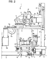
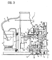
- Figures 2 and 3 are two schematic views in section taken on the line II-II of Figure 1, which illustrate the withdrawing and weighing device of the invention in two different possible working positions.
-
- In the drawings an installation for the storage and delivery of metered quantities of products such as, for example, dye products for use in the textile industry is generally indicated with the
reference numeral 1. - According to widely known criteria, the installation is essentially composed of a plurality of storage containers (or tubs) 2 within each of which there is a respective quantity of dyestuff, normally in the form of a fine powder, introduced by means of a suction line P from reference containers generally indicated H.
- Each
tub 2 is normally provided, usually at its lower end, with a delivery outlet 3 through which the product can be withdrawn from thetub 2 by the action of a delivery member 4. The delivery member is usually constituted by a screw conveyor operated according to criteria which will be better illustrated hereinafter. Preferably, and also here according to an arrangement known per se, above the screw conveyor delivery member 4 is located anagitator member 5 the function of which is to stir the product in the lower part of thetub 2 so as to facilitate its withdrawal and delivery through the outlet 3 avoiding the formation of lumps and clumps. - The
tubs 2 are arranged in a row (usually rectilinear or, possibly, in a closed loop) and located at a certain height on a base frame 6 of the installation, usually constituted by robust metal beams or the like. - The
tubs 2 are thus arranged with their delivery outlets 3 aligned at a certain height with respect to the plane of the ground T on which the framework 6 rests. The reference numeral 7 indicates a guide or rail assembly which extends along (and preferably below) the line along which the outlets 3 are aligned. A withdrawal carriage 8, also usually constituted by a solid frame (for example of metal beams) is movably disposed (usually by means of rollers) on the guides or rails 7 so as to be movable along the row oftubs 2 so as to displace a respective withdrawal table 9 beneath the delivery outlets 3. In use, on the table 9 are disposed withdrawal containers typically constituted by buckets S intended to receive metered quantities of the products contained in thetubs 2 delivered through the outlets 3. - The
reference numeral 10 generally indicates a suction structure provided withsuction inlets 11 intended also to move along the row oftubs 2 in correspondence with the delivery outlets 3, for the purpose of collecting the volatile substances (dust, fumes etc) which may possibly develop during the delivery of the products into the containers S thereby preventing such volatile products from dispersing into the environment. Thesuction structure 10 is connected to a subatmospheric pressure (depression) source not illustrated. Thereference numeral 12 indicates an (electric and/or fluidic) motor which, via generally known transmission elements, not illustrated in detail and schematically indicated 13, control the movement of the withdrawal carriage 8 along the guides 7. - In use of the installation the carriage 8 is successively brought (for example on the basis of a working sequence controlled by a processor system such as a mini processor or typically a so-called PLC) beneath the tub or
tubs 2 from which it is desired to withdraw respective quantities of the product. The withdrawal of the product from the or each tub involved causes (under the control of an operator, or preferably in an automatic manner controlled by the mini processor or PLC which supervises the operation of the installation 1) the delivery outlet 3 to be maintained open and/or the respective delivery member 4 to be maintained in operation until a balance 14 (typically of electronic type) mounted above the withdrawal carriage 8 and which supports the bucket S, indicates that the desired quantity of product has been delivered into the bucket S itself. - All the above is formed according to criteria known per se which therefore does not need to be described further in detail in this description, especially because it is per se not strictly relevant to the understanding of the operation of the present invention.
- In the arrangement according to the invention, substantially coextensively with respect to the guides 7 (for example in the exemplary arrangement illustrated in the attached drawings, in an intermediate position with respect to the rails 7) is located a
support structure 16 constituted, in the illustrated embodiment, by a track formed by two rails 17 (preferably two hollow metal sections) which rest on the ground T via support elements such aslegs 18. Preferably these are adjustable support elements which are finely adjustable in that they are provided with height-adjustable screw feet. This arrangement, or other equivalents, make it possible to achieve an exact horizontal orientation (in general an exact collinearity) of thesupport structure 16 with the path of movement of the carriage 8. - As opposed to the guides 7, with which the carriage 8 constantly maintains a rolling contact relationship, the
support structure 16 is intended to come into contact with thebalance 14, supporting it only when thebalance 14 is effectively utilised for performing a weighing operation. - To this end beneath the
balance 14 are respective legs (or equivalent support structures) 20 also preferably adjustable in a micro metric manner, intended to rest on therails 17. Simultaneously, the balance is also supported in a raised position by asupport structure 21 preferably having a bracket-like configuration, mounted on the carriage 8 by respectivevertical guides 21a with the interposition of a lifting unit comprising one or morefluid pressure actuators 22. Thesupport structure 21 and thebalance 14 which is located on it are therefore capable of vertical translation between a "movement" position (illustrated in Figure 2) in which the actuator oractuators 22 maintain thesupport structure 21 in a raised position ensuring that the balance 14 (and in particular its support formations 20) are raised with respect to thesupport structure 16, and a "working" position (illustrated in Figure 3) in which the actuator oractuators 22 lower thesupport structure 21 as far as necessary to make thebalance 14 rest with itssupport formations 20 on thesupport structure 16. - Preferably, leg formations 23 (or equivalent means) project upwardly from the
support structure 21 theupper ends 23a of which leg formations are able to cooperate with the structure defining the support table 9 on which the bucket S is disposed. All this in such a way as to ensure that, in the raised "movement" position (Figure 2) thebalance 14 is separated from and spaced from not only thesupport structure 16 but also the bucket S: this is so that the table 9 on which - in use - the bucket S is located is supported by theupper ends 23a of thelegs 23 so as to maintain them separated from the weighing platform (schematically indicated 14a) of thebalance 14. - On the other hand, when the actuator or
actuators 22 lower thesupport structure 21 towards the "working" position making thebalance 14 rest on thesupport structure 16, thelegs 23 also descend downwardly sufficient to disengage the support table 9 which, still carrying the bucket S, descends onto theplatform 14a of the balance as illustrated in greater detail in Figure 3. - The above-indicated result is obtainable, for example, by the relative dimensioning of the
balance 14, itssupport formations 20, the table 9 and thelegs 23. All this working in such a way that in the overall lifting movement of thesupport structure 21 the upper ends of thelegs 23a engage the support table 9 (and the container S which is located on it) lifting it with respect to theplatform 14a of the balance slightly before thebalance 14 is raised, again by thesupport structure 21, from thesupport structure 16. - In a complementary way, during the lowering movement, the
support structure 21 first lowers thebalance 14 onto thesupport structure 16 and then descends further by a distance necessary to make theupper end 23a of thelegs 23 deposit the support table 9 (and the container S which is located on it) onto theplatform 14a of the balance. - Preferably the
suction inlets 11 are mounted on the carriage 8 with the ability to move to and from with respect to the mouth of the bucket S which is located on thebalance 14 so as to be displaceable between a generally retracted position (Figure 2), utilised when the carriage 8 moves the bucket S past thetubs 2, and an extended position (Figure 3) utilised when delivery of the products from respective tubs 2 (Figure 3) takes place. This movement, which is achieved under the action of anactuator element 11a, is made possible by the connection between theinlets 11 and thesuction tank 10 made by means of an associatedflexible tube 11b. It will be appreciated that the assembly constituted by thesuction tank 10, theinlets 11 and theflexible tube 11b, as well as theactuator 11a (also subject to the PLC which superintends the overall operation of the installation 1) is mounted on the carriage 8, whilst themain suction tank 10a is a fixed structure with respect to which thesuction tank 10 is movable in a manner generally similar to that described in utility model IT-U-197,122 owned by the same Applicant. - Preferably, and again for the same purposes, that is to say to limit as much as possible the dispersion of the volatile substances, the carriage 8 is provided with a
cover panel 15 on its front face (that is to say on the outer side with respect to the installation, which is that usually observed by the operator who supervises the operation of the installation 1). Typically this may be a sheet, possibly folded, of rigid material such as stainless steel or the like which defines an outer containment wall of the region in which the delivery of products takes place. - In a preferred embodiment of the invention the uppermost part of the carriage 8 (thus its part most closely adjacent the delivery outlets 3 of the tubs 1) carries a further unit or
assembly 24 translatable in height onguides 24a under the action of at least one further fluid pressure actuator indicated 25. - The
actuator 25, like the actuator oractuators 22 just described, are also subjected to control by the same member, (for example a PLC) which supervises the general operation of theinstallation 1. - On the
assembly 24 is mounted a drive unit comprising one, although in the preferred embodiment illustrated here there are two, motors (also of electric or fluid type) indicated with thereference numerals toothed wheels motors tub 2 in front of which the carriage 8 is located from time to time during performance of the product withdrawal and weighing operation. This arrangement avoids having to associate a respective product delivery/agitation unit with eachtub 2. In practice, by adopting the arrangement according to the preferred embodiment of the invention, eachtub 2 is simply provided with a passive structure (constituted by the screw conveyor 4 and, if present, the agitator 5) which projects from the front of therespective tub 2 with respectivetoothed wheels shutter unit 29 carried by the screw conveyor 4. Theunit 29 is intended to close the delivery outlet 3 and, when driven to open, to uncover the respective outlet 3 allowing delivery of product through it. - Except for the structural differences of the elements and the associated controlled members (remembering also that the presence of the
agitator 5, in addition to the conveyor 4, is optional) the function of the twomotors movable assembly 24 is generally identical, which makes a separate description of them superfluous. - In this connection it will be sufficient to note that the
assembly 24 is also movable vertically on theguides 24a between a raised position (Figure 2) in which therespective drive wheels motors toothed wheels agitator 5 and a position (Figure 3) in which theassembly 24 carries thetoothed wheels motors toothed wheels - It is entirely apparent that, with the
assembly 24 in the raised position, thetoothed wheels motors toothed wheels tubs 2 so that, in these conditions, free movement of the carriage 8 along the guides 7 is possible. - Consequently, during the withdrawal and weighing operation (which takes place in a known manner already set out in the introductory part of the present description) the carriage 8 and the members which are located on it are generally placed in two different operating positions, that is to say:
- a raised or "movement" position in which the carriage
8 is free to move on the guides 7 under the action of
the
motor 12 to bring it into correspondence with thetub 2 from which it is to withdraw a certain quantity of product, and - a lowered or "working" position assumed when the
carriage 8, moving on the guides 7, has reached the
tub 2 in question and is positioned to make a metered delivery of the product into the bucket S. - In the "movement" position the following conditions are achieved according to the previously described mode of operation,
- the
balance 14, is raised by thesupport structure 21 with respect to thesupport structure 16 and at the same time the bucket S, resting on the table 9, is maintained raised (by thelegs 23 in the embodiment illustrated here) with respect to theweighing platform 14a of thebalance 14, - the
suction inlets 11 are located in the retracted position with respect to thebalance 14 and therefore with respect to the bucket S, - the
actuator 28 is in a disengagement position with respect to theactuation unit 29, which maintains the delivery outlets 3 of thetubs 2 in the closure position, and - the
assembly 24 is in a raised position so that themotors agitators 5 of thevarious tubs 2. This movement condition is shown in Figure 2. - In the working position illustrated in Figure 3 the following conditions are achieved:
- the
support structure 21 is lowered so that thebalance 14 rests on thesupport structure 16, whilst the container S rests on the table 9 in turn resting on theplatform 14a of thebalance 14; - the
suction outlets 11 are projected forwardly over thebalance 14 towards the region in which delivery of the product into the bucket S takes place, - the delivery outlet 3 of the
tub 2 in front of which the carriage 8 is located is open to effect displacement of the associatedclosure structure 29 moved by theactuator 28, and - the
assembly 24 is lowered so as to bring thetoothed drive wheels motors toothed wheels agitator 5. - In the said working position, with the
suction inlets 11 activated, themotor 26 drives the screw conveyor 4 so as to cause product to flow out from the tub 2 (preliminary agitated by theagitator 5 driven by themotor 27 so as to eliminate lumps or clumps) through the outlet 3 opened by the separation of theclosure structure 29 moved by theactuator 28. The delivered product thus falls into the underlying bucket S whilst possible dispersion of volatile substances into the environment is effectively countered partly by the presence of thescreen 15 but, above all, by the suction action taking place through theinlets 11. The withdrawal operation continues until thebalance 14 verifies that the desired quantity has fallen into the container S (preliminarily determined in a manner generally considered known, for example under the control of a program introduced into the processor which controls the installation 1). - Having completed the delivery action the carriage 8 is brought back into the movement position illustrated in Figure 2. It is therefore again free to move along the guides 7 to take the bucket S in front of another
tub 2 from which it is desired to withdraw a determined quantity of product (or to the outlet from the installation when the previously delivered product is the last determined withdrawal in the sequence of metered delivery). - It will be appreciated that the presence of the
support structure 16, precisely adjustable in conditions of very high precision, on which thebalance 14 is supported during the weighing operations, ensures that thebalance 14 itself can operate in ideal conditions avoiding imprecisions and intrinsic uncertainty of those situations in which the balance 14: - is partly supported, even during the performance of the weighing operation, by the carriage 8 which carries it beneath the delivery outlet 3 from the tubs and/or
- supports the bucket S on its weighing platform, even during displacement between different withdrawal positions.
- Moreover, the arrangement according to the invention prevents vibrations which develop during delivery of the product by the effect of the energisation of the
motors balance 14.
Claims (26)
- A device for withdrawing and weighing products comprising:characterised in that it comprises:a guide structure (7) defining a path of movement,a carriage (8) movable on the said guide structure (7) along the said path of movement between a plurality of product weighing and withdrawal positions, andweighing means (14) carried by the said carriage (8) so as to be movable along the said patha support structure (16) for the said weighing means (14) substantially coextensive with the said guide structure (7), andsupport means (21) associated with the said carriage (8) to support the said weighing means (14); the said support means (21, 22) being selectively movable between a raised position in which the said support means (21) maintain the said weighing means (14) raised with respect to the said support structure (16), and a lowered position in which the said weighing means (14) rest on the said support structure (16).
- A device according to Claim 1, characterised in that the said support structure (16) carries associated position adjustment means (19, 20).
- A device according to Claim 2, characterised in that the said position adjustment means (19, 20) comprise support feet (20) of adjustable height.
- A device according to any of Claims from 1 to 3, characterised in that the said support structure (16) includes a plurality of rail formations (17).
- A device according to any preceding claim, characterised in that the said guide structure (7) includes facing guide elements (7) and in that the said support structure (16) is mounted in an intermediate position with respect to the said guide elements (7).
- A device according to any preceding claim, characterised in that the said weighing means (14) are provided with respective support formations (20) capable of resting on the said support structure (16).
- A device according to any preceding claim, characterised in that the said weighing means (14) have an associated weighing platform (14a) capable of supporting, in use, at least one container (S) for receiving the said products and in that the said support means (21) have lifting formations (23) capable of cooperating with the said container (S) when the said support means (21) are in the said raised position to maintain the said container (S) raised with respect to the said weighing platform (14a).
- A device according to Claim 7, characterised in that the said lifting formations (23) are constituted by upwardly projecting leg elements (23a) extending from the said support means (21) for cooperating with the bottom part of the said container (S).
- A device according to Claim 7 or Claim 8, characterised in that the said weighing platform (14a) carries an associated intermediate support element (9) for supporting the said container (S) in support relationship on the said weighing platform (14a), and in that the said lifting formations (23) cooperate with the said intermediate support element (9).
- A device according to any of Claims from 7 to 9, characterised in that the said lifting formations (23) cooperate with the said container (S) in such a way that, in movement of the said support means (21) from the said lowered position to the said raised position the said lifting formations (23) lift the said container (S) from the said weighing platform (14a) before the said support means (21) lift the said weighing means (14) from the said support structure (16) and, conversely, when moving from the said raised position to the said lowered position the said support means (21) lower the said weighing means (14) onto the said support structure (16) before the said lifting formations (23) lower the said container (S) onto the said weighing platform (14a).
- A device according to any preceding claim, characterised in that the said support means (21) are moved by fluid actuator means (22).
- A device according to any preceding claim, characterised in that the said support means (21) have a generally bracket-like structure and are movably mounted on vertically slidable guides (21a).
- A device according to any preceding claim, characterised in that it includes suction means (10, 11) movable between a generally retracted disengagement position with respect to the said weighing means (14) and an advanced position in which the said suction means (11) project above the said weighing means (14) to suck volatile substances which can develop during the withdrawal of the said products.
- A device according to Claim 13, characterised in that the said suction means comprise:a source (10a) of subatmospheric pressure mounted in a fixed position with respect to the said guide structure (7) and substantially coextensive therewith, andan assembly of movable parts (10, 11) including the said suction inlets (11) mounted on the said carriage (8).
- A device according to any preceding claim, characterised in that the said carriage (8) is provided with a wall (15) covering the regions in which the said weighing means (14) are located to contain the dispersion of volatile substances which can develop during the withdrawal of the said product.
- A device according to any preceding claim, intended to cooperate in use with a row of storage containers (2) containing respective products for delivery, the said storage containers (2) having respective delivery outlets (3) arranged along a path substantially coextensive with the said path of movement of the said carriage (8) and having associated delivery means (4) selectively operable to effect delivery of a respective product through a respective delivery outlet (3), characterised in that the said carriage (8) carries at least one associated motor (26) capable of cooperating, in each of the said product withdrawal and weighing positions, with a respective actuating member (4a) of the delivery means (4) associated with one of the said storage containers (2).
- A device according to Claim 16, characterised in that it includes a support assembly (24) for the said motor (26) movable between a movement position in which the said motor (26) is disengaged from the actuating members (4a) of the delivery means (4) associated with the said storage containers (2) and a working position in which the said motor (26) operates in driving relation with an actuating member (4a) of the delivery means (4) associated with one of the said storage containers (2).
- A device according to Claim 16 or Claim 17, characterised in that the said motor (26) is provided with a toothed driving wheel (26a), and in that the said delivery means (4) are provided with respective toothed driven wheels (4a) which can cooperate in meshing relationship with the said toothed wheel (26a) of the said motor (26).
- A device according to Claim 17, characterised in that the movement of the said motor (26) between the said movement position and the said working position takes place by a substantially vertical translation.
- A device according to any of preceding claim, intended to cooperate, in use, with a row of storage containers (2) containing respective products to be delivered, the said storage containers (2) having associated respective agitator means (5) selectively operable to effect agitation of respective products for delivery, characterised in that the said carriage (8) carries at least one further associated motor (27) capable of cooperating, in each of the said withdrawal and weighing positions, with a respective actuating member (5a) of the agitator means (5) associated with one of the said storage containers (2).
- A device according to Claim 20, characterised in that it includes a support assembly (24) for the said further motor (27) movable between a movement position, in which the said further motor (27) is disengaged from the actuating members (5a) of the agitator means (5) associated with the said storage containers (2) and a working position in which the said further motor (27) operates in driving relationship with an actuating member (5a) of the agitator means (5) associated with one of the said storage containers (2).
- A device according to Claim 20 or Claim 21, characterised in that the said further motor (27) is provided with a respective toothed driving wheel (27a), and in that the said agitator means (5) are provided with respective further toothed driven wheels (5a) capable of cooperating in meshing relationship with the toothed wheel (27a) of the said further motor (27).
- A device according to Claim 21, characterised in that the movement of the said further motor (27) between the said movement position and the said working position is achieved by the effect of a substantially vertical translation.
- A device according to Claim 17 and Claim 21, characterised in that it includes a single assembly (24) on which are mounted both the said motor (26) and the said further motor (27).
- A device according to any of Claims 17, 21 or 24, characterised in that the said assembly (24) has associated therewith fluid actuating means (25).
- A device according to any of Claims 17, 21, 24 or 25, characterised in that the said assembly (24) is mounted on respective vertically extending guide means (24a).
Applications Claiming Priority (2)
| Application Number | Priority Date | Filing Date | Title |
|---|---|---|---|
| ITTO950833 | 1995-10-17 | ||
| IT95TO000833A IT1280975B1 (en) | 1995-10-17 | 1995-10-17 | DEVICE FOR SAMPLE AND WEIGHING OF PRODUCTS SUCH AS, FOR EXAMPLE, DYE PRODUCTS IN TEXTILE PLANTS. |
Publications (3)
| Publication Number | Publication Date |
|---|---|
| EP0769686A2 EP0769686A2 (en) | 1997-04-23 |
| EP0769686A3 EP0769686A3 (en) | 1998-04-15 |
| EP0769686B1 true EP0769686B1 (en) | 2001-12-05 |
Family
ID=11413889
Family Applications (1)
| Application Number | Title | Priority Date | Filing Date |
|---|---|---|---|
| EP96116572A Expired - Lifetime EP0769686B1 (en) | 1995-10-17 | 1996-10-16 | A device for withdrawing and weighing products such as dyes in textile plants |
Country Status (6)
| Country | Link |
|---|---|
| US (1) | US5835982A (en) |
| EP (1) | EP0769686B1 (en) |
| AT (1) | ATE210282T1 (en) |
| DE (1) | DE69617603D1 (en) |
| IT (1) | IT1280975B1 (en) |
| PT (1) | PT769686E (en) |
Cited By (1)
| Publication number | Priority date | Publication date | Assignee | Title |
|---|---|---|---|---|
| US6898549B1 (en) | 2000-07-07 | 2005-05-24 | Transtech Pharma, Inc. | Automated systems for weighing and/or liquid delivery |
Families Citing this family (20)
| Publication number | Priority date | Publication date | Assignee | Title |
|---|---|---|---|---|
| JP3486729B2 (en) * | 1997-10-28 | 2004-01-13 | Ykk株式会社 | Powder material metering device |
| ES2169957B1 (en) * | 1998-07-17 | 2003-04-16 | Ind Quimicas Kupsa S L | EQUIPMENT FOR DOSAGE AND MIXING BASIC COMPONENTS, HOMOGENIZED MOMENTS BEFORE ITS DOSAGE AND MIXING. |
| US6307163B1 (en) * | 1999-04-02 | 2001-10-23 | United Microelectronics Corp. | Chemical mixer tank calibrator and calibrating method for the same |
| US6148877A (en) * | 1999-04-22 | 2000-11-21 | Bethke; Steven D. | Fluid filling system with fill time optimization |
| CH694475A5 (en) * | 1999-07-08 | 2005-01-31 | Mettler Toledo Gmbh | A method of operating a balance and apparatus for performing the method. |
| US7521220B2 (en) * | 1999-11-26 | 2009-04-21 | Crucell Holland B.V. | Production of vaccines |
| CH709629B1 (en) * | 2000-10-06 | 2015-11-30 | Chemspeed Technologies Ag | A device having a tool holder, a tool and a scale. |
| US6725890B1 (en) * | 2003-04-09 | 2004-04-27 | Specialty Equipment Fabrication Company | Apparatus and method for automatically handling and filling drums |
| DE102005014930A1 (en) * | 2005-04-01 | 2006-10-05 | Azo Holding Gmbh | Plant for the gravimetric merging of bulk material components |
| FR2888321B1 (en) * | 2005-07-06 | 2007-10-05 | Serac Group Soc Par Actions Si | PONDERAL FILLING SYSTEM OF CONTAINERS WITH ENGAGEMENT OF THE FILLING FILLERS IN THE CONTAINERS |
| US7543979B2 (en) * | 2006-03-15 | 2009-06-09 | Neng-Kuei Yeh | Measuring apparatus for micro-amount of materials |
| JP2009014429A (en) * | 2007-07-03 | 2009-01-22 | Seiko Epson Corp | Weighing apparatus, droplet discharge device and weighing method |
| US9851240B2 (en) * | 2008-03-06 | 2017-12-26 | Nicole Sollazzo Lee | Precision measurement dispenser |
| ITTO20080557A1 (en) * | 2008-07-18 | 2010-01-19 | Lawer S P A | GRAVIMETRIC DOSING MACHINE, PARTICULARLY FOR FOOD PRODUCTS |
| DE102008046960A1 (en) * | 2008-09-12 | 2010-03-25 | Azo Holding Gmbh | Plant for gravimetric dosing of various bulk components |
| US9552462B2 (en) * | 2008-12-23 | 2017-01-24 | Exxonmobil Upstream Research Company | Method for predicting composition of petroleum |
| ITTO20110232A1 (en) * | 2011-03-14 | 2011-06-13 | Hero Europ S R L | AUTOMATIC TINTING. |
| US8919210B2 (en) | 2012-11-27 | 2014-12-30 | Life Technologies Corporation | Load cell lockouts and related fluid dispensing systems |
| CN104803207A (en) * | 2013-06-03 | 2015-07-29 | 杭州三拓印染设备技术开发有限公司 | Powdery dyestuff feeding device with rotary-dialing mechanical arm |
| IT201800006154A1 (en) * | 2018-06-08 | 2019-12-08 | DISPENSING MACHINE AND RELATED METHOD FOR PREPARING A USER DEFINED FORMULATION BY DISPENSING FLUID PRODUCTS |
Family Cites Families (9)
| Publication number | Priority date | Publication date | Assignee | Title |
|---|---|---|---|---|
| CH650849A5 (en) * | 1981-02-23 | 1985-08-15 | K Tron Soder Ag | ESSENTIALLY CLOSED CONTAINER WITH A COMPRESSED GAS CONNECTION OPENING INTO THE INTERIOR OF THE CONTAINER FOR THE SUPPLY OF INert GAS FOR INSTALLATION ON A SCALE. |
| IT1210567B (en) * | 1987-04-22 | 1989-09-14 | Color Service Srl | AUTOMATIC WEIGHING SYSTEM FOR POWDER DYES. |
| IT1211592B (en) | 1987-12-10 | 1989-11-03 | Lawer Srl | Fabrics colouring compsn. |
| DE8802510U1 (en) * | 1988-02-26 | 1988-06-30 | Braumiller, Werner, 8311 Lalling, De | |
| DK0406164T3 (en) * | 1989-06-27 | 1993-02-08 | Ciba Geigy Ag | Apparatus for dispensing dry and / or powdered bulk material, especially dye powder |
| US5115876A (en) * | 1991-03-11 | 1992-05-26 | Gain Lab Corp. | Automatic weighing system for powder |
| IT1251482B (en) * | 1991-09-17 | 1995-05-15 | Ind Automation Systems | EQUIPMENT FOR DISPENSING AND DOSING OF SUBSTANCES TO THE BULK STATE |
| JPH06190263A (en) * | 1992-12-24 | 1994-07-12 | Tsukishima Kikai Co Ltd | Compounding device of powdery raw material substance |
| US5345041A (en) * | 1993-04-26 | 1994-09-06 | Swanson Scott J | Apparatus for dispensing and weighing granular material |
-
1995
- 1995-10-17 IT IT95TO000833A patent/IT1280975B1/en active IP Right Grant
-
1996
- 1996-10-16 AT AT96116572T patent/ATE210282T1/en active
- 1996-10-16 EP EP96116572A patent/EP0769686B1/en not_active Expired - Lifetime
- 1996-10-16 PT PT96116572T patent/PT769686E/en unknown
- 1996-10-16 US US08/732,665 patent/US5835982A/en not_active Expired - Fee Related
- 1996-10-16 DE DE69617603T patent/DE69617603D1/en not_active Expired - Lifetime
Cited By (1)
| Publication number | Priority date | Publication date | Assignee | Title |
|---|---|---|---|---|
| US6898549B1 (en) | 2000-07-07 | 2005-05-24 | Transtech Pharma, Inc. | Automated systems for weighing and/or liquid delivery |
Also Published As
| Publication number | Publication date |
|---|---|
| IT1280975B1 (en) | 1998-02-11 |
| EP0769686A2 (en) | 1997-04-23 |
| ITTO950833A0 (en) | 1995-10-17 |
| PT769686E (en) | 2002-05-31 |
| ITTO950833A1 (en) | 1997-04-17 |
| DE69617603D1 (en) | 2002-01-17 |
| ATE210282T1 (en) | 2001-12-15 |
| EP0769686A3 (en) | 1998-04-15 |
| US5835982A (en) | 1998-11-10 |
Similar Documents
| Publication | Publication Date | Title |
|---|---|---|
| EP0769686B1 (en) | A device for withdrawing and weighing products such as dyes in textile plants | |
| US6849809B2 (en) | Balance with a weighing compartment | |
| JP5665758B2 (en) | Device for dispensing products in petri dishes | |
| JP7127241B2 (en) | Printer unit and 3D printer | |
| EP1673195A1 (en) | Laser processing installation with integrated loading/unloading of workpieces and laser motion cutting unit mounted on a same rail track | |
| US20060225808A1 (en) | Installation for gravimetrical combining of bulk product components | |
| US2520380A (en) | Beverage dispensing apparatus | |
| JPH11266636A (en) | Transplanter | |
| CN209128560U (en) | Automatic charging equipment during re metal electrolyzing | |
| CN109338417A (en) | Automatic charging equipment and automatic feeding method during re metal electrolyzing | |
| CN210332549U (en) | Feeding device for producing polyvinyl chloride | |
| US3967548A (en) | Waste compactor | |
| US3625490A (en) | Compact unit for preparing concrete | |
| DE4124911A1 (en) | DEVICE FOR RECEIVING A POWDER CONTAINER | |
| AU2004235594B2 (en) | Agitator loading system | |
| EP0358847A1 (en) | Method and apparatus for filling cases with easily damaged products, such as fruits, in a water tank | |
| EP0493341A1 (en) | A device for collecting a sliver of textile fibres | |
| CN219044707U (en) | Ton bag feeding equipment with fool-proof cover plate function | |
| US4089424A (en) | Device for removing coke oven chamber door | |
| CN213509473U (en) | Loading attachment is used in precious construction of backfill | |
| CN217677734U (en) | Automatic change high-efficient wicking treatment facility | |
| CN115991321B (en) | Packaging machine suitable for mixing various materials | |
| CN217535452U (en) | Concatenation formula quantitative weighing device with transfer function | |
| WO2002090216A2 (en) | A stock-and picking device | |
| CN215923531U (en) | Meal delivery device |
Legal Events
| Date | Code | Title | Description |
|---|---|---|---|
| PUAI | Public reference made under article 153(3) epc to a published international application that has entered the european phase |
Free format text: ORIGINAL CODE: 0009012 |
|
| AK | Designated contracting states |
Kind code of ref document: A2 Designated state(s): AT BE CH DE ES FR GB GR IT LI NL PT |
|
| PUAL | Search report despatched |
Free format text: ORIGINAL CODE: 0009013 |
|
| AK | Designated contracting states |
Kind code of ref document: A3 Designated state(s): AT BE CH DE ES FR GB GR IT LI NL PT |
|
| 17P | Request for examination filed |
Effective date: 19980918 |
|
| GRAG | Despatch of communication of intention to grant |
Free format text: ORIGINAL CODE: EPIDOS AGRA |
|
| GRAG | Despatch of communication of intention to grant |
Free format text: ORIGINAL CODE: EPIDOS AGRA |
|
| GRAH | Despatch of communication of intention to grant a patent |
Free format text: ORIGINAL CODE: EPIDOS IGRA |
|
| 17Q | First examination report despatched |
Effective date: 20010515 |
|
| RAP1 | Party data changed (applicant data changed or rights of an application transferred) |
Owner name: LAWER S.P.A. |
|
| GRAH | Despatch of communication of intention to grant a patent |
Free format text: ORIGINAL CODE: EPIDOS IGRA |
|
| GRAA | (expected) grant |
Free format text: ORIGINAL CODE: 0009210 |
|
| AK | Designated contracting states |
Kind code of ref document: B1 Designated state(s): AT BE CH DE ES FR GB GR IT LI NL PT |
|
| PG25 | Lapsed in a contracting state [announced via postgrant information from national office to epo] |
Ref country code: NL Free format text: LAPSE BECAUSE OF FAILURE TO SUBMIT A TRANSLATION OF THE DESCRIPTION OR TO PAY THE FEE WITHIN THE PRESCRIBED TIME-LIMIT Effective date: 20011205 Ref country code: LI Free format text: LAPSE BECAUSE OF FAILURE TO SUBMIT A TRANSLATION OF THE DESCRIPTION OR TO PAY THE FEE WITHIN THE PRESCRIBED TIME-LIMIT Effective date: 20011205 Ref country code: GR Free format text: LAPSE BECAUSE OF FAILURE TO SUBMIT A TRANSLATION OF THE DESCRIPTION OR TO PAY THE FEE WITHIN THE PRESCRIBED TIME-LIMIT Effective date: 20011205 Ref country code: FR Free format text: LAPSE BECAUSE OF FAILURE TO SUBMIT A TRANSLATION OF THE DESCRIPTION OR TO PAY THE FEE WITHIN THE PRESCRIBED TIME-LIMIT Effective date: 20011205 Ref country code: CH Free format text: LAPSE BECAUSE OF FAILURE TO SUBMIT A TRANSLATION OF THE DESCRIPTION OR TO PAY THE FEE WITHIN THE PRESCRIBED TIME-LIMIT Effective date: 20011205 Ref country code: BE Free format text: LAPSE BECAUSE OF FAILURE TO SUBMIT A TRANSLATION OF THE DESCRIPTION OR TO PAY THE FEE WITHIN THE PRESCRIBED TIME-LIMIT Effective date: 20011205 Ref country code: AT Free format text: LAPSE BECAUSE OF FAILURE TO SUBMIT A TRANSLATION OF THE DESCRIPTION OR TO PAY THE FEE WITHIN THE PRESCRIBED TIME-LIMIT Effective date: 20011205 |
|
| REF | Corresponds to: |
Ref document number: 210282 Country of ref document: AT Date of ref document: 20011215 Kind code of ref document: T |
|
| REG | Reference to a national code |
Ref country code: CH Ref legal event code: EP |
|
| REG | Reference to a national code |
Ref country code: GB Ref legal event code: IF02 |
|
| REF | Corresponds to: |
Ref document number: 69617603 Country of ref document: DE Date of ref document: 20020117 |
|
| PG25 | Lapsed in a contracting state [announced via postgrant information from national office to epo] |
Ref country code: DE Free format text: LAPSE BECAUSE OF FAILURE TO SUBMIT A TRANSLATION OF THE DESCRIPTION OR TO PAY THE FEE WITHIN THE PRESCRIBED TIME-LIMIT Effective date: 20020306 |
|
| NLV1 | Nl: lapsed or annulled due to failure to fulfill the requirements of art. 29p and 29m of the patents act | ||
| REG | Reference to a national code |
Ref country code: PT Ref legal event code: SC4A Free format text: AVAILABILITY OF NATIONAL TRANSLATION Effective date: 20020226 |
|
| REG | Reference to a national code |
Ref country code: CH Ref legal event code: PL |
|
| PG25 | Lapsed in a contracting state [announced via postgrant information from national office to epo] |
Ref country code: ES Free format text: LAPSE BECAUSE OF FAILURE TO SUBMIT A TRANSLATION OF THE DESCRIPTION OR TO PAY THE FEE WITHIN THE PRESCRIBED TIME-LIMIT Effective date: 20020627 |
|
| PLBE | No opposition filed within time limit |
Free format text: ORIGINAL CODE: 0009261 |
|
| STAA | Information on the status of an ep patent application or granted ep patent |
Free format text: STATUS: NO OPPOSITION FILED WITHIN TIME LIMIT |
|
| PG25 | Lapsed in a contracting state [announced via postgrant information from national office to epo] |
Ref country code: GB Free format text: LAPSE BECAUSE OF NON-PAYMENT OF DUE FEES Effective date: 20021016 |
|
| EN | Fr: translation not filed | ||
| 26N | No opposition filed | ||
| GBPC | Gb: european patent ceased through non-payment of renewal fee |
Effective date: 20021016 |
|
| PGFP | Annual fee paid to national office [announced via postgrant information from national office to epo] |
Ref country code: PT Payment date: 20040908 Year of fee payment: 9 |
|
| PG25 | Lapsed in a contracting state [announced via postgrant information from national office to epo] |
Ref country code: IT Free format text: LAPSE BECAUSE OF NON-PAYMENT OF DUE FEES;WARNING: LAPSES OF ITALIAN PATENTS WITH EFFECTIVE DATE BEFORE 2007 MAY HAVE OCCURRED AT ANY TIME BEFORE 2007. THE CORRECT EFFECTIVE DATE MAY BE DIFFERENT FROM THE ONE RECORDED. Effective date: 20051016 |
|
| PG25 | Lapsed in a contracting state [announced via postgrant information from national office to epo] |
Ref country code: PT Free format text: LAPSE BECAUSE OF NON-PAYMENT OF DUE FEES Effective date: 20060417 |
|
| REG | Reference to a national code |
Ref country code: PT Ref legal event code: MM4A Effective date: 20060417 |