EP0769606B1 - Dispositif d'exploration d'une formation souterraine traversée par un puits horizontal comportant plusieurs capteurs - Google Patents
Dispositif d'exploration d'une formation souterraine traversée par un puits horizontal comportant plusieurs capteurs Download PDFInfo
- Publication number
- EP0769606B1 EP0769606B1 EP96402078A EP96402078A EP0769606B1 EP 0769606 B1 EP0769606 B1 EP 0769606B1 EP 96402078 A EP96402078 A EP 96402078A EP 96402078 A EP96402078 A EP 96402078A EP 0769606 B1 EP0769606 B1 EP 0769606B1
- Authority
- EP
- European Patent Office
- Prior art keywords
- tubular
- exploration
- tubular element
- well
- rigid
- Prior art date
- Legal status (The legal status is an assumption and is not a legal conclusion. Google has not performed a legal analysis and makes no representation as to the accuracy of the status listed.)
- Expired - Lifetime
Links
- 230000015572 biosynthetic process Effects 0.000 title claims description 8
- 230000009975 flexible effect Effects 0.000 claims description 28
- 239000004020 conductor Substances 0.000 claims description 16
- 230000005484 gravity Effects 0.000 claims description 5
- 239000000463 material Substances 0.000 claims description 5
- 238000013016 damping Methods 0.000 claims description 3
- 238000000034 method Methods 0.000 description 5
- 230000005540 biological transmission Effects 0.000 description 4
- 230000003111 delayed effect Effects 0.000 description 4
- 230000000694 effects Effects 0.000 description 4
- 239000000523 sample Substances 0.000 description 4
- 230000009471 action Effects 0.000 description 3
- 230000008878 coupling Effects 0.000 description 3
- 238000010168 coupling process Methods 0.000 description 3
- 238000005859 coupling reaction Methods 0.000 description 3
- 125000006850 spacer group Chemical group 0.000 description 3
- 238000012544 monitoring process Methods 0.000 description 2
- 241000861223 Issus Species 0.000 description 1
- 229910000831 Steel Inorganic materials 0.000 description 1
- 241001080024 Telles Species 0.000 description 1
- 241001639412 Verres Species 0.000 description 1
- 239000006096 absorbing agent Substances 0.000 description 1
- XAGFODPZIPBFFR-UHFFFAOYSA-N aluminium Chemical compound [Al] XAGFODPZIPBFFR-UHFFFAOYSA-N 0.000 description 1
- 229910052782 aluminium Inorganic materials 0.000 description 1
- 239000011152 fibreglass Substances 0.000 description 1
- 239000012530 fluid Substances 0.000 description 1
- 239000003365 glass fiber Substances 0.000 description 1
- 238000002347 injection Methods 0.000 description 1
- 239000007924 injection Substances 0.000 description 1
- 238000009434 installation Methods 0.000 description 1
- 238000011900 installation process Methods 0.000 description 1
- 230000007774 longterm Effects 0.000 description 1
- 238000005259 measurement Methods 0.000 description 1
- 230000004044 response Effects 0.000 description 1
- 230000000630 rising effect Effects 0.000 description 1
- 230000035939 shock Effects 0.000 description 1
- 239000010959 steel Substances 0.000 description 1
Images

Classifications
-
- G—PHYSICS
- G01—MEASURING; TESTING
- G01V—GEOPHYSICS; GRAVITATIONAL MEASUREMENTS; DETECTING MASSES OR OBJECTS; TAGS
- G01V11/00—Prospecting or detecting by methods combining techniques covered by two or more of main groups G01V1/00 - G01V9/00
- G01V11/002—Details, e.g. power supply systems for logging instruments, transmitting or recording data, specially adapted for well logging, also if the prospecting method is irrelevant
- G01V11/005—Devices for positioning logging sondes with respect to the borehole wall
-
- E—FIXED CONSTRUCTIONS
- E21—EARTH OR ROCK DRILLING; MINING
- E21B—EARTH OR ROCK DRILLING; OBTAINING OIL, GAS, WATER, SOLUBLE OR MELTABLE MATERIALS OR A SLURRY OF MINERALS FROM WELLS
- E21B17/00—Drilling rods or pipes; Flexible drill strings; Kellies; Drill collars; Sucker rods; Cables; Casings; Tubings
- E21B17/10—Wear protectors; Centralising devices, e.g. stabilisers
- E21B17/1014—Flexible or expansible centering means, e.g. with pistons pressing against the wall of the well
- E21B17/1021—Flexible or expansible centering means, e.g. with pistons pressing against the wall of the well with articulated arms or arcuate springs
- E21B17/1028—Flexible or expansible centering means, e.g. with pistons pressing against the wall of the well with articulated arms or arcuate springs with arcuate springs only, e.g. baskets with outwardly bowed strips for cementing operations
-
- E—FIXED CONSTRUCTIONS
- E21—EARTH OR ROCK DRILLING; MINING
- E21B—EARTH OR ROCK DRILLING; OBTAINING OIL, GAS, WATER, SOLUBLE OR MELTABLE MATERIALS OR A SLURRY OF MINERALS FROM WELLS
- E21B47/00—Survey of boreholes or wells
- E21B47/01—Devices for supporting measuring instruments on drill bits, pipes, rods or wirelines; Protecting measuring instruments in boreholes against heat, shock, pressure or the like
Definitions
- the present invention relates to a device for exploring a formation underground passage through a well, adapted to operate in portions of wells where its progression under the effect of gravity is difficult and in particular in portions horizontal wells or strongly deviated from the vertical.
- the device according to the invention is particularly suitable for carrying out operations seismic prospecting underground.
- the seismic exploration of a geological formation by placing in one or more wells drilled through this formation a set of reception and / or emission to receive signals returned by discontinuities in the basement in response to seismic waves or acoustic emitted in a well or on the ground surface.
- Seismic equipment can be used in vertical portions or sufficiently vertical of the wells and in this case, they descended there by the effect of gravity.
- the seismic equipment is placed for example in a well tool or in several well tools arranged in a chain along an electro-carrying cable, as described for example in patents FR 2 501 380, 2 616 230, 2 636 741 of applicant.
- the applicant's patent FR 2 655 373 also discloses a system for conduct a non-rigid exploration device comprising several probes combined to each other by portions of electro-carrying cable, in a well where its progress by the effect of gravity, is hampered, in particular due to the inclination of the well in relation to the vertical.
- a device for delayed electrical connection is used to connect the probe assembly to a cable connected to a surface control and recording station.
- a current of fluid is established in the column to push the first probe out of it and allow the opening of anchor arms.
- the spring spacer means comprise for example flexible blades, each bearing at its ends on sleeves integral with each tubular element, on which the housings, and the decoupling means comprise sheaths made of a material shock absorber, interposed between each flexible blade and the tubular element corresponding.
- Each sleeve comprises for example a support element disposed between two end stops integral with the tubular element, and mechanically isolated by a sheath, the support element and stops, and the device comprises electrical connectors inside the rigid tubular elements for the electrical connection to the harness of electrical conductors associated with the elements sensitive.
- Each support element may for example have two parts arranged on either side of the tubular element, with interposition of the sheath, and means fixing to bring these two parts together and possibly indexing means to prevent rotation of the support elements relative to the element tubular.
- each flexible blade is integral at its ends with axes able to move in guide lights in plates integral with each support element.
- the spring spacer means have flexible blades on which the boxes are fixed, each blade flexible is engaged in a slot in the wall of the rod according to a generator and it is supported at its opposite ends on integral sleeves a rigid tube disposed inside each tubular element, the means of decoupling comprise sheaths of a damping material, interposed around each sleeve to acoustically isolate it from both the inner wall of the tubular element and the rigid tube, and each flexible blade is integral with its ends, axes which can move in guide lights provided in sleeves.
- the electrical connection means delayed include a multi-contact male plug, a tubular extension for the guiding in the connection block, of a multi-contact female socket connected to the multi-conductor cable, and means for locking the female socket in engagement position.
- the device comprises an element tubular head with an unbalance and an orientation indicator for determine the angular positioning of all exploration modules by compared to the vertical.
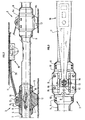
- the device consists (Fig. 1, 2) of a set of modules M1, Mi, Mi + 1, ..., Mn interconnected end to end.
- Each of these Mi modules has an element rigid tubular or rod 1, terminated at its two opposite ends by an end piece fixing 2 for its connection (by screwing for example) with those of the elements adjacent tubulars.
- Each sleeve 3 has a support element 4 disposed between two end stops 5, 6 rigidly fixed to the rod 1.
- a sheath made of a material elastic 7 is placed around the tubular element between each pair of stops 5, 6.
- the support elements 4 each comprise two half-shells 4a, 4b plated against the sheath 7 on either side of the tubular element and joined to one another by screws 8.
- At least one of the stops 5, 6 has an indexing lug 9 adapted to come engage in a corresponding cavity of one of the half-shells 4a by example.
- the decoupling sleeves 7 have end plates 10 for mechanically isolate the support elements 4 from their respective stops 5, 6.
- the device also includes a flexible blade 11 terminated at both opposite ends by a piece of end piece 12 provided with a cavity for an axis 13 (Fig. 2, 3).
- One of the half-shells 4a of each element of support 4 comprises two side plates 15 oriented parallel to the axis of the rods and provided with elongated openings 16 for guiding the axis 13 of each end piece.
- the sliding of each axis 13 gives each flexible blade 11 a certain flexing latitude.
- the opposite half-shell 4b of each support element 4 comprises a support shoe 17.
- each flexible blade 11 (Fig. 2), is fixed a box 18 for exploration instruments. They can be sensitive sensors in particular to acoustic or seismic waves. such as a triaxial geophone or "triphone" 19 by example.
- the electrical conductors 20 associated with these instruments exit from boxes 18 by watertight bushings (not shown) and pass along the flexible blade 11. They penetrate inside the rod 1 through an opening (not shown) at one of the support elements 4.
- a multi-pin connector 20a (Fig. 4) is placed inside each rod 1. It is accessible by removing a removable plate 21 covering an opening at through in the wall. On the pins of this connector 20a, are welded on the one hand electrical conductors 22 associated with the instruments in the housing 18 of the same module Mi, and on the other hand conductors 23 associated with other instruments in the following modules Mi + 1 ... Mn
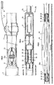
- Fig. 1 All of the modules interconnected end to end are associated (Fig. 1) with a first end to a tubular head element 24 provided with an unbalance and a orientation indicator (not shown) for determining the orientation of the unbalance relative to the vertical plane.
- a orientation indicator (not shown) for determining the orientation of the unbalance relative to the vertical plane.
- an indicator of a known type comprising a pendulum weight in contact with a runway potentiometer.
- connection block 26 provided with means for delayed electrical connection in humid environment.
- the block 26 comprises (Fig. 5) a tubular body 27, a male plug multi-contact 28 oriented along the axis of the body 27, at the center of an extension tubular guide 29 of section smaller than that of the body. which ends with a flange 30.
- This extension 29 is used for guiding a multi-contact socket 31, connected to the various conductors of a multi-conductor cable 32, which is adapted to fit onto the male plug 28.
- the socket 31 is surmounted by a bar tubular ballast 33. Locks 34 which can be remotely controlled from the surface, block the socket in the plug-in position on the plug 28.
- a cable 35 connects the multi-contact plug 28 to a sealed compartment 36 of the tubular body 27 containing an acquisition and transmission system 37 such as described for example in patent FR 2 688 896 of the applicant.
- the block of connection 26 is connected to maneuvering means 38 on the surface by through a drill string 39.
- the system 37 receives the signals transmitted to it by the beam 38 formed by successive addition at the connectors 21, of the conductors coming from respectively of the different boxes 18 associated with the set of modules M1 to Mn and to the orientation indicator in the tubular head element 24. It digitizes them and code for their transmission to a central control station 40 and of recording placed on the surface.
- connection between the multi-conductor cable 32 and the central station 40 is made easier by the use of a special window fitting 41 ("side entry sub"), allowing, once it is in place, to modify the length of the drill string 39 without having to interrupt the conductive connections.
- the tubular head element 24 is engaged in the well and, by interconnections successive end to end, the different modules M1 to Mn, the intermediate rod 25, the connection block 26 and possibly a number of sections of the train rods 39. Then attach the special window fitting 40 into which the multi-contact socket 31 surmounted by its load bar 33. An injection head (not shown) is then associated with the rod train 39 to pump the multi-contact socket 31 until it comes to be inserted on the plug 28 of the block of connection 26.
- All modules can be moved at will by addition (or removal) to the drill pipe 39 of additional sections, so as to explore the formation on a greater length of well and make multiple covers.
- each module exploration has a single flexible blade 11 for applying a housing of instruments against the wall of the well, and a support shoe 17 diametrically opposite. It is quite obvious, however, that one can use M1-Mn exploration modules possibly comprising several flexible blades possibly carrying other instrument cases 18.
- Fig. 6 can include two flexible blades 11 each provided with a box for elements exploration such as geophones for example.
- the device has a tube rigid 41a of diameter smaller than that of each tubular element 1 which is arranged inside of it. It is held in place relative to it by two sleeves 42.
- An elastic sheath 43 is placed around each sleeve 42 for the acoustically decouple both tube 41 and the inner wall of the element tubular 1.
- the flexible blades 11 are partially engaged in grooves 44 formed along two opposite generatrices of each tubular element 1.
- the axes 13, at their opposite ends, can slide in guide slots 45 formed in the end pieces 42. With this method of attachment, each element tubular provides protection for flexible blade attachment sleeves when the device progresses along the well.
Landscapes
- Life Sciences & Earth Sciences (AREA)
- Engineering & Computer Science (AREA)
- Geology (AREA)
- Physics & Mathematics (AREA)
- Mining & Mineral Resources (AREA)
- General Life Sciences & Earth Sciences (AREA)
- Geophysics (AREA)
- Environmental & Geological Engineering (AREA)
- Fluid Mechanics (AREA)
- Geochemistry & Mineralogy (AREA)
- General Physics & Mathematics (AREA)
- Mechanical Engineering (AREA)
- Geophysics And Detection Of Objects (AREA)
- Buildings Adapted To Withstand Abnormal External Influences (AREA)
Description
- une pluralité de modules d'exploration rigides interconnectés bout à bout comprenant chacun un élément tubulaire rigide pourvu, à chacune de ses extrémités, de moyens de connexion avec au moins un autre élément tubulaire, au moins un boitier contenant des éléments sensibles, des moyens d'écartement à ressorts pour plaquer chaque boitier en permanence contre la paroi du puits ainsi que des moyens de découplage pour isoler mécaniquement chaque boitier, des éléments tubulaires;
- un câble de liaison connecté à une station centrale en surface; et
- un bloc de raccordement comprenant un système d'acquisition relié aux différents modules par un faisceau de conducteurs électriques passant à l'intérieur des éléments tubulaires, reliés aux éléments sensibles, pour collecter des signaux issus de ces différents éléments sensibles, et des moyens de connexion électrique différée en milieu humide entre le câble de liaison et le système d'acquisition, ce bloc de raccordement étant interposé entre l'ensemble des modules d'exploration et une colonne rigide reliée à des moyens de manoeuvre en surface pour conduire l'ensemble d'exploration jusque dans ladite portion du puits.
- il peut être constitué par interconnexion bout à bout d'un nombre variable de modules d'exploration banalisés associés par l'intermédiaire d'un bloc de raccordement, à un train de tiges que l'on allonge suffisamment pour le pousser jusque dans une portion de puits soit très inclinée soit conformée de telle manière qu'elle empêche la libre descente de l'ensemble des modules;
- les liaisons électriques entre les différents instruments ou capteurs sont tous réunis et protégés dans les éléments tubulaires.
- la Fig. 1 montre schématiquement l'ensemble du dispositif suivant un premier mode de réalisation, mis en place dans un puits dont une partie est horizontale;
- la Fig.2 montre schématiquement en coupe l'agencement de chaque module d'exploration;
- la Fig.3 montre plus en détail l'agencement d'un manchon re raccordement d'une lame flexible;
- la Fig.4 montre schématiquement le mode de connexion à un faisceau de conducteurs courant le long des éléments tubulaires, des conducteurs électriques associés àaux éléments sensibles;
- la Fig.5 montre schématiquement en coupe un bloc de raccordement de l'ensemble des modules d'exploration à un train de tiges remontant jusqu'à la surface; et
- la Fig.6 montre un deuxième mode de réalisation comportant deux lames flexibles associées aux éléments tubulaires par des moyens de fixation intérieurs à ces éléments.
- remplaçant les lames flexibles permettant le couplage des boitiers d'instruments avec la paroi du puits, par d'autres moyens de couplage tels que des patins reliés à des bras ouverts par action de moyens d'écartement tels que des moyens ressort;
- remplaçant l'ensemble d'acquisition unique 37 par des modules électroniques d'acquisition répartis dans différents éléments tubulaires 1 et communiquant les signaux acquis à un ensemble de codage et de transmission dans le bloc de raccordement 26;
- remplaçant les éléments tubulaires rigides par des éléments de câble multi-conducteurs semi-rigide avec une gaíne extérieure en fibres de verre;
- remplaçant les connecteurs mécaniques et électriques séparés 2 et 20A de la Fig. 4 par un mode de réalisation combiné où la connexion mécanique des éléments tubulaires entraíne un emboitement des connecteurs électriques, tel que décrit par exemple dans le brevet EP 290.338 du demandeur; ou en
- utilisant des éléments tubulaires 1 pourvus suivant une technique connue, de fentes destinées à réduire la vitesse de propagation des ondes le long de la colonne.
Claims (10)
- Dispositif d'exploration d'une formation souterraine traversée par un puits, adapté à être descendu dans une zone du puits où sa progression par gravité est difficile, et notamment dans une portion de puits fortement inclinée par rapport à la verticale, caractérisé en ce qu'il comporte :une pluralité de modules d'exploration rigides interconnectés bout à bout (M1-Mn) comprenant chacun un élément tubulaire rigide (1) pourvu, à chacune de ses extrémités, de moyens de connexion (2) avec au moins un autre élément tubulaire, au moins un boitier (18) contenant des éléments sensibles (19), des moyens d'écartement à ressorts (11) pour plaquer chaque boitier (18) en permanence contre la paroi du puits ainsi que des moyens de découplage (7, 10, 14) pour isoler mécaniquement chaque boitier, des éléments tubulaires (1);un câble de liaison (32) connecté à une station centrale (40) en surface; etun bloc de raccordement (26) comprenant un système de collecte (37) relié aux différents modules (M1-Mn) par un faisceau de conducteurs électriques (22) passant à l'intérieur des éléments tubulaires (1), reliés aux éléments sensibles (19), pour centraliser des signaux issus de ces différents éléments sensibles, et des moyens (28, 31) de connexion électrique différée en milieu humide entre le câble de liaison (32) et le système de collecte (37), ce bloc de raccordement (26) étant interposé entre l'ensemble des modules d'exploration (M1-Mn) et une colonne rigide (39) reliée à des moyens de maneuvre (38) en surface pour conduire l'ensemble d'exploration jusque dans ladite portion du puits.
- Dispositif selon la revendication 1, caractérisé en ce que les moyens d'écartement à ressorts comportent des lames flexibles (11), chacune en appui à ses extrémités sur des manchons (3) solidaires de chaque élément tubulaire (1), sur lesquelles sont fixés les boitiers (18), et les moyens de découplage comportent des gaines (7) en un matériau amortisseur, interposées entre chaque lame flexible (11) et l'élément tubulaire (1) correspondant.
- Dispositif selon la revendication 2, caractérisé en ce que chaque manchon (3) comporte un élément de support (4) disposé entre deux butées d'extrémité (5, 6) solidaires de l'élément tubulaire (1), et mécaniquement isolé par une gaine (7), de l'élément de support (4) et des butées (5, 6), le dispositif comportant des connecteurs électriques (20) à l'intérieur des éléments tubulaires rigides (1) pour la connexion électrique au faisceau des conducteurs électriques (22) associés aux éléments sensibles.
- Dispositif selon la revendication 3, caractérisé en ce que chaque élément de support comporte deux parties (4a, 4b) disposées de part et d'autre de l'élément tubulaire (1), avec interposition de la gaine (7), et des moyens de fixation (8) pour réunir ces deux parties.
- Dispositif selon la revendication 3 ou 4 caractérisé en ce qu'il comporte des moyens d'indexation (9) pour empêcher toute rotation des éléments de support par rapport à l'élément tubulaire (1).
- Dispositif selon l'une des revendications 3 à 5, caractérisé en ce que chaque lame flexible est solidaire à ses extrémités, d'axes pouvant se déplacer dans des lumières de guidage (16) ménagées dans des plaques (15) solidaires de chaque élément de support (4).
- Dispositif selon la revendication 1, caractérisé en ce que les moyens d'écartement à ressorts comportent des lames flexibles (11) sur lesquelles sont fixés les boitiers (18), chacune des lames flexibles (11) est engagée dans une fente (44) ménagée dans la paroi de la tige (1) suivant une génératrice et elle est en appui à ses extrémités opposées sur des manchons (42) solidaires d'un tube rigide (41) disposé à l'intérieur de chaque élément tubulaire (1), les moyens de découplage comportent des gaines (43) en un matériau amortisseur, interposées autour de chaque manchon (42) pour l'isoler acoustiquement à la fois de la paroi intérieure de l'élément tubulaire (1) et du tube rigide (41), et chaque lame flexible (11) est solidaire à ses extrémités, d'axes (13) pouvant se déplacer dans des lumières de guidage (45) ménagées dans les manchons (42).
- Dispositif selon l'une des revendications précédentes, caractérisé en ce que les moyens de connexion électrique différée, comportent une fiche mâle multi-contacts (28), un prolongement tubulaire (29, 30) pour le guidage dans le bloc de raccordement (26), d'une prise femelle multi-contacts (31) reliée au câble multi-conducteurs (32), et des moyens de verrouillage (34) de la prise femelle (31) en position d'engagement.
- Dispositif selon l'une des revendications précédentes, caractérisé en ce qu'il comporte un élément tubulaire de tête (24) comportant un balourd et un indicateur d'orientation pour déterminer le positionnement angulaire de l'ensemble des modules d'exploration (M1-Mn) par rapport à la verticale.
- Dispositif selon l'une des revendications précédentes, caractérisé en ce que la colonne rigide (39) comporte un raccord spécial à fenêtre pour le passage du câble de liaison (32).
Applications Claiming Priority (2)
| Application Number | Priority Date | Filing Date | Title |
|---|---|---|---|
| FR9512265 | 1995-10-17 | ||
| FR9512265A FR2739893B1 (fr) | 1995-10-17 | 1995-10-17 | Dispositif d'exploration d'une formation souterraine traversee par un puits horizontal comportant plusieurs capteurs couples en permanence avec la paroi |
Publications (2)
| Publication Number | Publication Date |
|---|---|
| EP0769606A1 EP0769606A1 (fr) | 1997-04-23 |
| EP0769606B1 true EP0769606B1 (fr) | 2001-04-04 |
Family
ID=9483680
Family Applications (1)
| Application Number | Title | Priority Date | Filing Date |
|---|---|---|---|
| EP96402078A Expired - Lifetime EP0769606B1 (fr) | 1995-10-17 | 1996-09-30 | Dispositif d'exploration d'une formation souterraine traversée par un puits horizontal comportant plusieurs capteurs |
Country Status (5)
| Country | Link |
|---|---|
| US (1) | US5801642A (fr) |
| EP (1) | EP0769606B1 (fr) |
| DK (1) | DK0769606T3 (fr) |
| FR (1) | FR2739893B1 (fr) |
| NO (1) | NO315991B1 (fr) |
Cited By (1)
| Publication number | Priority date | Publication date | Assignee | Title |
|---|---|---|---|---|
| CN105134092A (zh) * | 2015-08-05 | 2015-12-09 | 中国海洋石油总公司 | 中部封井注入低比重液的高温高压水平井完井管柱 |
Families Citing this family (16)
| Publication number | Priority date | Publication date | Assignee | Title |
|---|---|---|---|---|
| MY115236A (en) * | 1996-03-28 | 2003-04-30 | Shell Int Research | Method for monitoring well cementing operations |
| FR2787503B1 (fr) | 1998-12-18 | 2001-03-30 | Inst Francais Du Petrole | Systeme d'installation permanente des sondes de mesure a l'interieur d'un conduit par verrou amovible par pression de fluide |
| US6467387B1 (en) * | 2000-08-25 | 2002-10-22 | Schlumberger Technology Corporation | Apparatus and method for propelling a data sensing apparatus into a subsurface formation |
| GB2388133B (en) * | 2001-01-04 | 2004-12-29 | Schlumberger Holdings | Centralizer including measurement means |
| US20030218939A1 (en) * | 2002-01-29 | 2003-11-27 | Baker Hughes Incorporated | Deployment of downhole seismic sensors for microfracture detection |
| WO2003091540A1 (fr) * | 2002-04-25 | 2003-11-06 | Quantx Wellbore Instrumentation, Llc | Systeme et procede d'acquisition de donnees sismiques et microsismiques dans des forages devies |
| US6910534B2 (en) * | 2002-06-11 | 2005-06-28 | Halliburton Energy Services, Inc. | Apparatus for attaching a sensor to a tubing string |
| US20050257961A1 (en) * | 2004-05-18 | 2005-11-24 | Adrian Snell | Equipment Housing for Downhole Measurements |
| FR2881789B1 (fr) * | 2005-02-04 | 2008-06-06 | Sercel Sa | Sonde de mesure et de traitement autonome pour pre-etude d'un puits |
| US7424928B2 (en) * | 2005-09-13 | 2008-09-16 | Dale Cox | Apparatus, system and method for flexibly coupling sensors to a downhole tool |
| US7735555B2 (en) * | 2006-03-30 | 2010-06-15 | Schlumberger Technology Corporation | Completion system having a sand control assembly, an inductive coupler, and a sensor proximate to the sand control assembly |
| WO2008093169A2 (fr) * | 2006-11-06 | 2008-08-07 | Magnitude Spas | Dispositif et procédé sismique de mémoire |
| US7813220B2 (en) * | 2006-12-04 | 2010-10-12 | Schlumberger Technology Corporation | Method and apparatus for long term seismic monitoring |
| FR2914419B1 (fr) * | 2007-03-30 | 2009-10-23 | Datc Europ Sa | Dispositif de protection d'une sonde geotechnique ou geophysique |
| FR2923615B1 (fr) * | 2007-11-12 | 2010-02-26 | Inst Francais Du Petrole | Source sismique permanente |
| US10113409B2 (en) * | 2016-07-12 | 2018-10-30 | Geonomic Technologies Inc. | Bore measuring tool |
Family Cites Families (15)
| Publication number | Priority date | Publication date | Assignee | Title |
|---|---|---|---|---|
| USRE32070E (en) * | 1961-08-31 | 1986-01-21 | Schlumberger Technology Corp. | Borehole apparatus for investigating subsurface earth formations including a plurality of pad members and means for regulating the bearing pressure thereof |
| US3282349A (en) * | 1964-01-22 | 1966-11-01 | Fenix & Scisson Inc | Casing centralizer |
| US3991850A (en) * | 1975-01-08 | 1976-11-16 | Schlumberger Technology Corporation | Noise-attenuating positioners for acoustic well-logging tools |
| FR2512488A1 (fr) * | 1981-09-09 | 1983-03-11 | Schlumberger Prospection | Procede et dispositif de diagraphie utilisant une sonde equipee de patins de mesure |
| FR2547861B1 (fr) * | 1983-06-22 | 1987-03-20 | Inst Francais Du Petrole | Methode et dispositif de mesure et d'intervention dans un puits |
| US4757873A (en) * | 1986-11-25 | 1988-07-19 | Nl Industries, Inc. | Articulated transducer pad assembly for acoustic logging tool |
| FR2636741B1 (fr) * | 1988-09-21 | 1991-03-22 | Inst Francais Du Petrole | Systeme de reception de signaux pouvant etre couple avec la paroi d'un puits ou forage |
| US5146050A (en) * | 1989-04-25 | 1992-09-08 | Western Atlas International, Inc. | Method and apparatus for acoustic formation dip logging |
| US4979585A (en) * | 1989-10-02 | 1990-12-25 | Halliburton Logging Services, Inc. | Compound suspension linkage |
| FR2656034B1 (fr) * | 1989-12-20 | 1992-04-24 | Inst Francais Du Petrole | Sonde de puits pouvant etre decouplee d'une liaison rigide qui la relie a la surface. |
| USH1192H (en) * | 1990-10-26 | 1993-06-01 | Exxon Production Research Company | Low-torque centralizer |
| US5212354A (en) * | 1991-02-07 | 1993-05-18 | Exxon Production Research Company | Apparatus and method for detecting seismic waves in a borehole using multiple clamping detector units |
| FR2674029B1 (fr) * | 1991-03-11 | 1993-06-11 | Inst Francais Du Petrole | Methode et appareillage de prospection par ondes acoustiques dans des puits de production. |
| US5330364A (en) * | 1992-01-31 | 1994-07-19 | Amoco Corporation | Electrical connector for well surveying tool |
| US5502686A (en) * | 1994-08-01 | 1996-03-26 | Western Atlas International | Method and apparatus for imaging a borehole sidewall |
-
1995
- 1995-10-17 FR FR9512265A patent/FR2739893B1/fr not_active Expired - Fee Related
-
1996
- 1996-09-30 DK DK96402078T patent/DK0769606T3/da active
- 1996-09-30 EP EP96402078A patent/EP0769606B1/fr not_active Expired - Lifetime
- 1996-10-15 US US08/732,596 patent/US5801642A/en not_active Expired - Fee Related
- 1996-10-15 NO NO19964390A patent/NO315991B1/no unknown
Cited By (1)
| Publication number | Priority date | Publication date | Assignee | Title |
|---|---|---|---|---|
| CN105134092A (zh) * | 2015-08-05 | 2015-12-09 | 中国海洋石油总公司 | 中部封井注入低比重液的高温高压水平井完井管柱 |
Also Published As
| Publication number | Publication date |
|---|---|
| FR2739893B1 (fr) | 1997-12-12 |
| NO315991B1 (no) | 2003-11-24 |
| NO964390D0 (no) | 1996-10-15 |
| US5801642A (en) | 1998-09-01 |
| EP0769606A1 (fr) | 1997-04-23 |
| DK0769606T3 (da) | 2001-05-07 |
| NO964390L (no) | 1997-04-18 |
| FR2739893A1 (fr) | 1997-04-18 |
Similar Documents
| Publication | Publication Date | Title |
|---|---|---|
| EP0769606B1 (fr) | Dispositif d'exploration d'une formation souterraine traversée par un puits horizontal comportant plusieurs capteurs | |
| EP0773344B1 (fr) | Dispositif d'exploration d'une formation souterraine traversée par un puits horizontal comportant plusieurs sondes ancrables | |
| CA2078467C (fr) | Dispositif perfectionne de surveillance d'un gisement pour puits de production | |
| US6728165B1 (en) | Acoustic sensing system for downhole seismic applications utilizing an array of fiber optic sensors | |
| EP0558379B1 (fr) | Système et méthode d'acquisition de données physiques liées à un forage en cours | |
| CA2014045C (fr) | Methode et dispositif de prospection sismique dans des puits et notamment des puits devies | |
| EP0546892B1 (fr) | Procédé et dispositif pour l'interconnexion électrique d'appareils tels que de sondes de puits | |
| FR2600172A1 (fr) | Dispositif d'installation de capteurs sismiques dans un puits de production petroliere | |
| FR2910925A1 (fr) | Systeme et procede de telemetrie dans les puits de forage | |
| EP3356638B1 (fr) | Articulation rotoïde optique dans des applications de tube spiralé | |
| CA1287160C (fr) | Procede et dispositif d'installation de capteurs sismiques dans un puits de production petroliere | |
| EP0433126B1 (fr) | Système pour déplacer un dispositif d'exploration non rigide dans un puits dévié ou étroit | |
| JP2003522957A (ja) | 地震波受信装置および地震波受信装置を下層土などの固体媒体に結合する方法 | |
| Butler et al. | Hawaii‐2 observatory pioneers opportunities for remote instrumentation in ocean studies | |
| EP0774674B1 (fr) | Méthode et dispositif de prospection sismique utilisant un outil de forage en action dans un puits | |
| EP0574295B1 (fr) | Système sismique mobile de grande longueur pour puits | |
| EP0296933B1 (fr) | Procédé et dispositif pour la prospection sismique d'un milieu, à partir d'ondes induites créées artificiellement dans un puit | |
| FR2593292A1 (fr) | Procede et dispositif d'installation de capteurs sismiques dans un puits de production petroliere | |
| EP0457644B1 (fr) | Système de réception d'ondes acoustiques pour puits permettant un découplage mécanique des capteurs | |
| FR2666113A1 (fr) | Procede et appareil de forage de trous de sondage et ensemble de trepan pour la mise en óoeuvre de ce procede. | |
| Butler et al. | The Hawaii-2 Observatory (H2O) |
Legal Events
| Date | Code | Title | Description |
|---|---|---|---|
| PUAI | Public reference made under article 153(3) epc to a published international application that has entered the european phase |
Free format text: ORIGINAL CODE: 0009012 |
|
| AK | Designated contracting states |
Kind code of ref document: A1 Designated state(s): DK GB IT NL |
|
| 17P | Request for examination filed |
Effective date: 19971023 |
|
| GRAG | Despatch of communication of intention to grant |
Free format text: ORIGINAL CODE: EPIDOS AGRA |
|
| 17Q | First examination report despatched |
Effective date: 20000629 |
|
| GRAG | Despatch of communication of intention to grant |
Free format text: ORIGINAL CODE: EPIDOS AGRA |
|
| GRAH | Despatch of communication of intention to grant a patent |
Free format text: ORIGINAL CODE: EPIDOS IGRA |
|
| ITF | It: translation for a ep patent filed |
Owner name: DE DOMINICIS & MAYER S.R.L. |
|
| GRAH | Despatch of communication of intention to grant a patent |
Free format text: ORIGINAL CODE: EPIDOS IGRA |
|
| GRAA | (expected) grant |
Free format text: ORIGINAL CODE: 0009210 |
|
| AK | Designated contracting states |
Kind code of ref document: B1 Designated state(s): DK GB IT NL |
|
| GBT | Gb: translation of ep patent filed (gb section 77(6)(a)/1977) |
Effective date: 20010404 |
|
| REG | Reference to a national code |
Ref country code: DK Ref legal event code: T3 |
|
| REG | Reference to a national code |
Ref country code: GB Ref legal event code: IF02 |
|
| PLBE | No opposition filed within time limit |
Free format text: ORIGINAL CODE: 0009261 |
|
| STAA | Information on the status of an ep patent application or granted ep patent |
Free format text: STATUS: NO OPPOSITION FILED WITHIN TIME LIMIT |
|
| 26N | No opposition filed | ||
| PGFP | Annual fee paid to national office [announced via postgrant information from national office to epo] |
Ref country code: DK Payment date: 20040830 Year of fee payment: 9 |
|
| PGFP | Annual fee paid to national office [announced via postgrant information from national office to epo] |
Ref country code: NL Payment date: 20040929 Year of fee payment: 9 |
|
| PG25 | Lapsed in a contracting state [announced via postgrant information from national office to epo] |
Ref country code: IT Free format text: LAPSE BECAUSE OF NON-PAYMENT OF DUE FEES;WARNING: LAPSES OF ITALIAN PATENTS WITH EFFECTIVE DATE BEFORE 2007 MAY HAVE OCCURRED AT ANY TIME BEFORE 2007. THE CORRECT EFFECTIVE DATE MAY BE DIFFERENT FROM THE ONE RECORDED. Effective date: 20050930 Ref country code: DK Free format text: LAPSE BECAUSE OF NON-PAYMENT OF DUE FEES Effective date: 20050930 |
|
| PG25 | Lapsed in a contracting state [announced via postgrant information from national office to epo] |
Ref country code: NL Free format text: LAPSE BECAUSE OF NON-PAYMENT OF DUE FEES Effective date: 20060401 |
|
| REG | Reference to a national code |
Ref country code: DK Ref legal event code: EBP |
|
| NLV4 | Nl: lapsed or anulled due to non-payment of the annual fee |
Effective date: 20060401 |
|
| PGFP | Annual fee paid to national office [announced via postgrant information from national office to epo] |
Ref country code: GB Payment date: 20070917 Year of fee payment: 12 |
|
| GBPC | Gb: european patent ceased through non-payment of renewal fee |
Effective date: 20080930 |
|
| PG25 | Lapsed in a contracting state [announced via postgrant information from national office to epo] |
Ref country code: GB Free format text: LAPSE BECAUSE OF NON-PAYMENT OF DUE FEES Effective date: 20080930 |