EP0769606A1 - Exploration device for a subterranean formation traversed by a horizontal well comprising a plurality of sensors - Google Patents
Exploration device for a subterranean formation traversed by a horizontal well comprising a plurality of sensors Download PDFInfo
- Publication number
- EP0769606A1 EP0769606A1 EP96402078A EP96402078A EP0769606A1 EP 0769606 A1 EP0769606 A1 EP 0769606A1 EP 96402078 A EP96402078 A EP 96402078A EP 96402078 A EP96402078 A EP 96402078A EP 0769606 A1 EP0769606 A1 EP 0769606A1
- Authority
- EP
- European Patent Office
- Prior art keywords
- tubular
- tubular element
- well
- exploration
- rigid
- Prior art date
- Legal status (The legal status is an assumption and is not a legal conclusion. Google has not performed a legal analysis and makes no representation as to the accuracy of the status listed.)
- Granted
Links
- 230000015572 biosynthetic process Effects 0.000 title claims description 8
- 239000004020 conductor Substances 0.000 claims abstract description 17
- 230000009975 flexible effect Effects 0.000 claims description 28
- 230000005484 gravity Effects 0.000 claims description 5
- 238000013016 damping Methods 0.000 claims description 4
- 239000000463 material Substances 0.000 claims description 4
- 230000003111 delayed effect Effects 0.000 claims description 3
- 125000006850 spacer group Chemical group 0.000 claims description 3
- 238000000034 method Methods 0.000 description 6
- 230000005540 biological transmission Effects 0.000 description 4
- 230000000694 effects Effects 0.000 description 4
- 239000000523 sample Substances 0.000 description 4
- 230000009471 action Effects 0.000 description 3
- 230000008878 coupling Effects 0.000 description 3
- 238000010168 coupling process Methods 0.000 description 3
- 238000005859 coupling reaction Methods 0.000 description 3
- 238000009434 installation Methods 0.000 description 3
- 238000012544 monitoring process Methods 0.000 description 2
- 241000861223 Issus Species 0.000 description 1
- 229910000831 Steel Inorganic materials 0.000 description 1
- 241001080024 Telles Species 0.000 description 1
- 241001639412 Verres Species 0.000 description 1
- XAGFODPZIPBFFR-UHFFFAOYSA-N aluminium Chemical compound [Al] XAGFODPZIPBFFR-UHFFFAOYSA-N 0.000 description 1
- 229910052782 aluminium Inorganic materials 0.000 description 1
- 238000004873 anchoring Methods 0.000 description 1
- 239000013013 elastic material Substances 0.000 description 1
- 239000011152 fibreglass Substances 0.000 description 1
- 239000012530 fluid Substances 0.000 description 1
- 239000003365 glass fiber Substances 0.000 description 1
- 238000002347 injection Methods 0.000 description 1
- 239000007924 injection Substances 0.000 description 1
- 230000007774 longterm Effects 0.000 description 1
- 238000004519 manufacturing process Methods 0.000 description 1
- 238000005259 measurement Methods 0.000 description 1
- 230000004044 response Effects 0.000 description 1
- 230000000630 rising effect Effects 0.000 description 1
- 239000010959 steel Substances 0.000 description 1
Images


Classifications
-
- G—PHYSICS
- G01—MEASURING; TESTING
- G01V—GEOPHYSICS; GRAVITATIONAL MEASUREMENTS; DETECTING MASSES OR OBJECTS; TAGS
- G01V11/00—Prospecting or detecting by methods combining techniques covered by two or more of main groups G01V1/00 - G01V9/00
- G01V11/002—Details, e.g. power supply systems for logging instruments, transmitting or recording data, specially adapted for well logging, also if the prospecting method is irrelevant
- G01V11/005—Devices for positioning logging sondes with respect to the borehole wall
-
- E—FIXED CONSTRUCTIONS
- E21—EARTH DRILLING; MINING
- E21B—EARTH DRILLING, e.g. DEEP DRILLING; OBTAINING OIL, GAS, WATER, SOLUBLE OR MELTABLE MATERIALS OR A SLURRY OF MINERALS FROM WELLS
- E21B17/00—Drilling rods or pipes; Flexible drill strings; Kellies; Drill collars; Sucker rods; Cables; Casings; Tubings
- E21B17/10—Wear protectors; Centralising devices, e.g. stabilisers
- E21B17/1014—Flexible or expansible centering means, e.g. with pistons pressing against the wall of the well
- E21B17/1021—Flexible or expansible centering means, e.g. with pistons pressing against the wall of the well with articulated arms or arcuate springs
- E21B17/1028—Flexible or expansible centering means, e.g. with pistons pressing against the wall of the well with articulated arms or arcuate springs with arcuate springs only, e.g. baskets with outwardly bowed strips for cementing operations
-
- E—FIXED CONSTRUCTIONS
- E21—EARTH DRILLING; MINING
- E21B—EARTH DRILLING, e.g. DEEP DRILLING; OBTAINING OIL, GAS, WATER, SOLUBLE OR MELTABLE MATERIALS OR A SLURRY OF MINERALS FROM WELLS
- E21B47/00—Survey of boreholes or wells
- E21B47/01—Devices for supporting measuring instruments on drill bits, pipes, rods or wirelines; Protecting measuring instruments in boreholes against heat, shock, pressure or the like
Landscapes
- Life Sciences & Earth Sciences (AREA)
- Engineering & Computer Science (AREA)
- Geology (AREA)
- Physics & Mathematics (AREA)
- Mining & Mineral Resources (AREA)
- General Life Sciences & Earth Sciences (AREA)
- Geophysics (AREA)
- Environmental & Geological Engineering (AREA)
- Fluid Mechanics (AREA)
- Geochemistry & Mineralogy (AREA)
- General Physics & Mathematics (AREA)
- Mechanical Engineering (AREA)
- Geophysics And Detection Of Objects (AREA)
- Buildings Adapted To Withstand Abnormal External Influences (AREA)
Abstract
Description
La présente invention concerne un dispositif d'exploration d'une formation souterraine traversée par un puits, adapté à fonctionner dans des portions de puits où sa progression sous l'effet de la gravité est difficile et notamment dans des portions de puits horizontales ou fortement déviées par rapport à la verticale.The present invention relates to a device for exploring an underground formation traversed by a well, adapted to operate in portions of wells where its progression under the effect of gravity is difficult and in particular in portions of wells which are horizontal or strongly deviated. with respect to the vertical.
Le dispositif selon l'invention convient notamment pour réaliser des opérations de prospection sismique du sous sol.The device according to the invention is particularly suitable for carrying out seismic prospecting operations underground.
Suivant une technique connue, on réalise l'exploration sismique d'une formation géologique en disposant dans un ou plusieurs puits forés au travers de cette formation un ensemble de réception et/ou d'émission pour capter des signaux renvoyés par les discontinuités du sous-sol en réponse à des ondes sismiques ou acoustiques émises dans un puits ou à la surface du sol.According to a known technique, seismic exploration of a geological formation is carried out by placing in one or more wells drilled through this formation a reception and / or emission assembly for picking up signals returned by the discontinuities of the sub- ground in response to seismic or acoustic waves emitted in a well or on the ground surface.
Les équipements sismiques peuvent être utilisées dans des portions verticales ou suffisamment verticales des puits et dans ce cas, ils y sont descendus par l'effet de la gravité.The seismic equipment can be used in vertical or sufficiently vertical portions of the wells and in this case, they are lowered there by the effect of gravity.
Les équipements sismiques sont placés par exemple dans un outil de puits ou dans plusieurs outils de puits disposés en chapelet le long d'un câble électro-porteur, comme décrits par exemple dans les brevets FR 2 501 380, 2 616 230, 2 636 741 du demandeur.The seismic equipment is placed for example in a well tool or in several well tools arranged in a chain along an electrically-carrying cable, as described for example in the
Par les brevets FR 2 656 034 et 2 674 029 du demandeur, on connait une méthode de prospection sismique d'une formation géologique comportant l'utilisation d'un dispositif de réception comprenant une ou plusieurs unités de réception qui sont mis en place dans un puits vertical au moyen d'une colonne de production. Les unités sont conduites jusqu'à la profondeur d'installation et sont plaquées contre la paroi du puits ou bien contre un tube de cuvelage. Le couplage peut être fait au moyen de patins ou de bras pouvant s'écarter de la colonne sous l'action de ressorts. Ces unités peuvent encore être placées dans des boitiers que l'on écarte de la colonne et que l'on découple mécaniquement de celle-ci.By the
Par le brevet FR 2 703 470 du demandeur, on connait un procédé d'installation dans un ou plusieurs puits traversant une zone souterraine, d'un ensemble d'émission-réception d'ondes sismiques ou acoustiques comportant par exemple des transducteurs émetteurs-récepteurs qui peuvent être installés derrière une colonne tubulaire utilisée pour d'autres fonctions et reliées de façon permanente ou non par des câbles à une station de commande et d'enregistrement en surface. Avec un tel ensemble, on réalise par exemple des diagraphies des couches environnant chaque puits en ondes P ou S, et effectuer ainsi une surveillance de longue durée d'un gisement.By
Par le brevet FR 2 655 373 du demandeur, on connait aussi un système pour conduire un dispositif d'exploration non rigide comportant plusieurs sondes réunies les unes aux autres par des portions de câble électro-porteur, dans un puits où sa progression par l'effet de la gravité, est gênée, enraison notamment de l'inclinaison du puits par rapport à la verticale. On guide ce dispositif vers une zone de puits déviée au moyen d'une colonne tubulaire formée d'un train de tiges. Un dispositif de connexion électrique différée est utilisé pour connecter l'ensemble de sondes à un câble relié à une station de commande et d'enregistrement en surface. Un courant de fluide est établi dans la colonne pour pousser la première sonde hors de celle-ci et permettre l'ouverture de bras d'ancrage. Par une traction sur la colonne, on fait alors sortir l'ensemble des sondes dans le puits et l'on porocède à des cycles de mesure.By
Le dispositif selon l'invention permet de réaliser l'exploration d'une formation souterraine traversée par un puits, et il est adapté à être descendu dans une zone du puits où sa progression sous l'effet de la gravité est difficile, et notamment dans une portion de puits fortement inclinée par rapport à la verticale. Il est caractérisé en ce qu'il comporte :
- une pluralité de modules d'exploration rigides interconnectés bout à bout comprenant chacun un élément tubulaire rigide pourvu, à chacune de ses extrémités, de moyens de connexion avec au moins un autre élément tubulaire, au moins un boitier contenant des éléments sensibles, des moyens d'écartement à ressorts pour plaquer chaque boitier en permanence contre la paroi du puits ainsi que des moyens de découplage pour isoler mécaniquement chaque boitier, des éléments tubulaires;
- un câble de liaison connecté à une station centrale en surface; et
- un bloc de raccordement comprenant un système d'acquisition relié aux différents modules par un faisceau de conducteurs électriques passant à l'intérieur des éléments tubulaires, reliés aux éléments sensibles, pour collecter des signaux issus de ces différents éléments sensibles, et des moyens de connexion électrique différée en milieu humide entre le câble de liaison et le système d'acquisition, ce bloc de raccordement étant interposé entre l'ensemble des modules d'exploration et une colonne rigide reliée à des moyens de manoeuvre en surface pour conduire l'ensemble d'exploration jusque dans ladite portion du puits.
- a plurality of rigid exploration modules interconnected end to end each comprising a rigid tubular element provided, at each of its ends, with connection means with at least one other tubular element, at least one housing containing sensitive elements, means for 'spacer with springs to press each box permanently against the wall of the well as well as decoupling means to mechanically isolate each box from tubular elements;
- a connecting cable connected to a central station on the surface; and
- a connection block comprising an acquisition system connected to the different modules by a bundle of electrical conductors passing inside the tubular elements, connected to the sensitive elements, for collecting signals from these different sensitive elements, and connection means delayed electrical connection between the connecting cable and the acquisition system, this connection block being interposed between all of the exploration modules and a rigid column connected to surface maneuvering means to drive all of the exploration into said portion of the well.
Suivant un mode de réalisation, les moyens d'écartement à ressorts comportent par exemple des lames flexibles, chacune en appui à ses extrémités sur des manchons solidaires de chaque élément tubulaire, sur lesquelles sont fixés les boitiers, et les moyens de découplage comportent des gaînes en un matériau amortisseur, interposées entre chaque lame flexible et l'élément tubulaire correspondant.According to one embodiment, the spring spacing means comprise for example flexible blades, each bearing at its ends on sleeves integral with each tubular element, on which the housings are fixed, and the decoupling means comprise sheaths made of a damping material, interposed between each flexible blade and the corresponding tubular element.
Chaque manchon comporte par exemple un élément de support disposé entre deux butées d'extrémité solidaires de l'élément tubulaire, et mécaniquement isolé par une gaîne, de l'élément de support et des butées, et le dispositif comporte des connecteurs électriques à l'intérieur des éléments tubulaires rigides pour la connexion électrique au faisceau des conducteurs électriques associés aux éléments sensibles.Each sleeve comprises for example a support element disposed between two end stops integral with the tubular element, and mechanically insulated by a sheath, from the support element and stops, and the device comprises electrical connectors at the interior of rigid tubular elements for electrical connection to the harness of electrical conductors associated with sensitive elements.
Chaque élément de support peut comporter par exemple deux parties disposées de part et d'autre de l'élément tubulaire, avec interposition de la gaîne, et des moyens de fixation pour réunir ces deux parties et éventuellement des moyens d'indexation pour empêcher toute rotation des éléments de support par rapport à l'élément tubulaire.Each support element may for example comprise two parts arranged on either side of the tubular element, with interposition of the sheath, and fixing means for joining these two parts and possibly indexing means to prevent any rotation. support elements relative to the tubular element.
De préférence, chaque lame flexible est solidaire à ses extrémités, d'axes pouvant se déplacer dans des lumières de guidage dans des plaques solidaires de chaque élément de support.Preferably, each flexible blade is integral at its ends with axes which can move in guide slots in plates integral with each support element.
Suivant un autre mode de réalisation, les moyens d'écartement à ressorts comportent des lames flexibles sur lesquelles sont fixés les boitiers, chaque lame flexible est engagée dans une fente ménagée dans la paroi de la tige suivant une génératrice et elle est en appui à ses extrémités opposées sur des manchons solidaires d'un tube rigide disposé à l'intérieur de chaque élément tubulaire, les moyens de découplage comportent des gaînes en un matériau amortisseur, interposées autour de chaque manchon pour l'isoler acoustiquement à la fois de la paroi intérieure de l'élément tubulaire et du tube rigide, et chaque lame flexible est solidaire à ses extrémités, d'axes pouvant se déplacer dans des lumières de guidage ménagées dans les manchons.According to another embodiment, the spring spacing means comprise flexible blades on which the housings are fixed, each flexible blade is engaged in a slot made in the wall of the rod according to a generator and it is supported at its opposite ends on sleeves integral with a rigid tube disposed inside each tubular element, the decoupling means comprise sheaths of a damping material, interposed around each sleeve to isolate it acoustically from both the interior wall of the tubular element and of the rigid tube, and each flexible blade is secured at its ends, to axes which can move in guide slots made in the sleeves.
Suivant un autre mode de réalisation, les moyens de connexion électrique différée, comportent une fiche mâle multi-contacts, un prolongement tubulaire pour le guidage dans le bloc de raccordement, d'une prise femelle multi-contacts reliée au câble multi-conducteurs, et des moyens de verrouillage de la prise femelle en position d'engagement.According to another embodiment, the deferred electrical connection means comprise a multi-contact male plug, a tubular extension for guiding in the connection block, a multi-contact female socket connected to the multi-conductor cable, and means for locking the socket in the engagement position.
Suivant un mode particulier de réalisation le dispositif comporte un élément tubulaire de tête comportant un balourd et un indicateur d'orientation pour déterminer le positionnement angulaire de l'ensemble des modules d'exploration par rapport à la verticale.According to a particular embodiment, the device comprises a tubular head element comprising an unbalance and an orientation indicator for determining the angular positioning of all of the exploration modules relative to the vertical.
Le dispositif selon l'invention est avantageux en ce que :
- il peut être constitué par interconnexion bout à bout d'un nombre variable de modules d'exploration banalisés associés par l'intermédiaire d'un bloc de raccordement, à un train de tiges que l'on allonge suffisamment pour le pousser jusque dans une portion de puits soit très inclinée soit conformée de telle manière qu'elle empêche la libre descente de l'ensemble des modules;
- les liaisons électriques entre les différents instruments ou capteurs sont tous réunis et protégés dans les éléments tubulaires.
- it can be formed by end-to-end interconnection of a variable number of standardized exploration modules associated via a connection block, with a string of rods that are extended enough to push it into a portion well either very inclined or shaped so that it prevents the free descent of all the modules;
- the electrical connections between the various instruments or sensors are all united and protected in the tubular elements.
D'autres caractéristiques et avantages du dispositif selon l'invention, apparaîtront à la lecture de la description ci-après de modes de réalisation décrits à titre d'exemples non limitatifs, en se référant aux dessins annexés où :
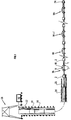
- la Fig. 1 montre schématiquement l'ensemble du dispositif suivant un premier mode de réalisation, mis en place dans un puits dont une partie est horizontale;
- la Fig.2 montre schématiquement en coupe l'agencement de chaque module d'exploration;
- la Fig.3 montre plus en détail l'agencement d'un manchon re raccordement d'une lame flexible;
- la Fig.4 montre schématiquement le mode de connexion à un faisceau de conducteurs courant le long des éléments tubulaires, des conducteurs électriques associés àaux éléments sensibles;
- la Fig.5 montre schématiquement en coupe un bloc de raccordement de l'ensemble des modules d'exploration à un train de tiges remontant jusqu'à la surface; et
- la Fig.6 montre un deuxième mode de réalisation comportant deux lames flexibles associées aux éléments tubulaires par des moyens de fixation intérieurs à ces éléments.
- Fig. 1 schematically shows the entire device according to a first embodiment, placed in a well, part of which is horizontal;
- Fig.2 schematically shows in section the arrangement of each exploration module;
- Fig.3 shows in more detail the arrangement of a sleeve re connection of a flexible blade;
- Fig.4 shows schematically the mode of connection to a bundle of conductors running along the tubular elements, electrical conductors associated with sensitive elements;
- Fig.5 schematically shows in section a connection block of all the exploration modules to a drill string rising to the surface; and
- Fig.6 shows a second embodiment comprising two flexible blades associated with the tubular elements by internal fixing means to these elements.
Le dispositif est constitué (Fig.1, 2) d'un ensemble de modules M1, Mi, Mi+1,..., Mn interconnectés bout à bout. Chacun de ces modules Mi comporte un élément tubulaire rigide ou tige 1, terminé à ses deux extrémités opposés par un embout de fixation 2 pour son raccordement (par vissage par exemple) avec ceux des éléments tubulaires adjacents. Sur chaque tige 1, à distance l'un de l'autre, sont disposés deux manchons 3. Chaque manchon 3 comporte un élément de support 4 disposé entre deux butées d'extrémité 5, 6 fixées rigidement à la tige 1. Une gaîne en un matériau élastique 7 est placée autour de l'élément tubulaire entre chaque paire de butées 5, 6. Les éléments de support 4 comportent chacun deux demi-coquilles 4a, 4b plaquées contre la gaine 7 de part et d'autre de l'élément tubulaire et réunies l'une à l'autre par des vis 8. Pour empêcher toute rotation des éléments de support 4 autour des tiges 1, au moins une des butées 5, 6 comporte un ergot d'indexation 9 adapté à venir s'engager dans une cavité correspondante de l'une des demi-coquilles 4a par exemple. Les gaînes de découplage 7 comportent des plaques d'extrémité 10 pour isoler mécaniquement les éléments support 4 de leurs butées respectives 5, 6.The device consists (Fig. 1, 2) of a set of modules M1, Mi, Mi + 1, ..., Mn interconnected end to end. Each of these Mi modules comprises a rigid tubular element or
Le dispositif comporte également une lame flexible 11 terminée à ses deux extrémités opposées par une pièce d'embout 12 pourvue d'une cavité pour un axe 13 (Fig.2, 3). Un élément de découplage 14 du type "silent-block" par exemple, est disposé autour de chaque axe 13. Une des demi-coquilles 4a de chaque élément de support 4 comporte deux plaques latérales 15 orientées parallèlement à l'axe des tiges et pourvues d'ouvertures allongées 16 pour le guidage de l'axe 13 de chaque pièce d'embout. Le coulissement de chaque axe 13 offre à chaque lame flexible 11 une certaine latitude de fléchissement. La demi-coquille 4b opposée de chaque élément de support 4 comporte un sabot d'appui 17.The device also comprises a
A la partie médiane de chaque lame flexible 11 (Fig.2), est fixé un boitier 18 pour des instruments d'exploration. Il peut s'agir de capteurs sensibles notamment aux ondes acoustiques ou sismiques.tels qu'un géophone triaxial ou "triphone" 19 par exemple. Les conducteurs électriques 20 associés à ces instruments, sortent des boitiers 18 par des traversées étanches (non représentées) et passent le long de la lame flexible 11. Ils pénètrent à l'intérieur de la tige 1 par une ouverture (non représentée) au niveau de l'un des élément de support 4.At the middle part of each flexible blade 11 (Fig.2), is fixed a
Un connecteur multibroches 20 (Fig.4) est disposé à l'intérieur de chaque tige 1. Il est accessible en ôtant une plaque amovible 21 recouvrant une ouverture au travers dans la paroi. Aux broches de ce connecteur 20, sont soudés d'une part les conducteurs électriques 22 associés aux instruments dans le boitier 18 du même module Mi, et d'autre part des conducteurs 23 associés à d'autres instruments dans les modules suivants Mi+1... MnA multi-pin connector 20 (Fig.4) is disposed inside each
L'ensemble des modules interconnectés bout à bout, est associé (Fig. 1) à une première extrémité à un élément tubulaire de tête 24 pourvue d'un balourd et d'un indicateur d'orientation (non représenté) destiné à déterminer l'orientation du balourd relativement au plan vertical. On peut utiliser par exemple un indicateur d'un type connu comportant une masselotte pendulaire au contact d'une piste de potentiomètre.The set of modules interconnected end to end, is associated (Fig. 1) at a first end with a
A son extrémité opposée, l'élément tubulaire M1 est relié par une tige 25 à un bloc de raccordement 26 pourvu de moyens de connexion électrique différée en milieu humide. Le bloc 26 comporte (Fig.5) un corps tubulaire 27, une fiche mâle multi-contacts 28 orientée suivant l'axe du corps 27, au centre d'un prolongement tubulaire de guidage 29 de section inférieure à celle du corps. qui est terminé par une collerette 30. Ce prolongement 29 sert au guidage d'une prise femelle multi-contacts 31, connectée aux différents conducteurs d'un câble multi-conducteurs 32, qui est adaptée à venir s'emboiter sur la fiche mâle 28. La prise 31 est surmontée d'une barre de lestage tubulaire 33. Des verrous 34 pouvant être télécommandés depuis la surface, permettent de bloquer la prise en position d'enfichage sur la fiche 28.At its opposite end, the tubular element M1 is connected by a
Un câble 35 relie la fiche multi-contacts 28 à un compartiment étanche 36 du corps tubulaire 27 contenant un système d'acquisition et de transmission 37 tel que décrit par exemple dans le brevet FR 2 688 896 du demandeur. Le bloc de raccordement 26 est relié à des moyens de manoeuvre 38 en surface par l'intermédiaire d'un train de tiges 39.A
Le système 37 reçoit les signaux transmis jusqu'à lui par le faisceau 38 formé par adjonction successives au niveau des connecteurs 21, des conducteurs issus respectivement des différents boitiers 18 associés à l'ensemble de modules M1 à Mn et à l'indicateur d'orientation dans l'élément tubulaire de tête 24. Il les numérise et les code pour leur transmission à une station centrale 40 de commande et d'enregistrement placée en surface.The
Pour simplifier le montage de l'ensemble des modules d'exploration M1-Mn, on peut les banaliser en disposant de préférence dans chacun d'eux des connecteurs multibroches 21 identiques avec un nombre de broches suffisant pour l'interconnexion de tous les fils conducteurs qui aboutissent finalement à l'ensemble d'acquisition et de codage 37.To simplify the assembly of all the exploration modules M1-Mn, they can be trivialized by preferably having in each of them identical
Suivant un agencement connu notamment par le brevet FR-A-2 547 861 du demandeur, la connexion entre le câble multi-conducteurs 32 et la station centrale 40 est facilitée par l'emploi d'un raccord spécial à fenêtre 41 ("side entry sub"), permettant, une fois qu'il est en place, de modifier la longueur du train de tiges 39 sans avoir à interrompre les liaisons conductrices.According to an arrangement known in particular by patent FR-A-2,547,861 of the applicant, the connection between the
On peut constituer par exemple un ensemble d'exploration comportant 12 éléments tubulaires 1 d'une dizaine de mètres de long, en acier en aluminium ou en fibre de verre, associés chacun à un "triphone", et renfermant par exemple un connecteur électrique 20 à 61 broches permettant également la connexion électrique de l'indicateur d'orientation dans la section de tête 24.One can for example constitute an exploration unit comprising 12
La mise en place de l'ensemble des modules d'exploration M1 à Mn jusque dans une zone d'intervention dans un puits s'effectue de la façon suivante.The installation of all the exploration modules M1 to Mn as far as an intervention zone in a well is carried out as follows.
On engage dans le puits l'élément tubulaire de tête 24 et, par interconnexions successives bout à bout, les différents modules M1 à Mn, la tige intercalaire 25, le bloc de raccordement 26 et éventuellement un certain nombre de sections du train de tiges 39. On fixe ensuite le raccord spécial à fenêtre 41 dans lequel est introduit la prise multi-contacts 31 surmontée de sa barre de charge 33. Une tête d'injection (non représentée) est ensuite associée au train de tiges 39 pour pomper la prise multi-contacts 31 jusqu'à ce qu'elle vienne s'enficher sur la fiche 28 du bloc de raccordement 26.The
On rajoute alors suffisamment de sections au train de tiges 39 de façon à amener l'ensemble de modules M1-Mn jusqu'à la zone du puits où l'on va procéder à des opérations d'exploration. En surveillant depuis la station de surface 41 les indications du détecteur d'orientation dans l'élément de tête à balourd 24 et en faisant tourner suffisamment sur lui-même le train de tiges 39 au cours de sa progression, on peut orienter les différents modules M1 à Mn de façon que les lames flexibles 11 et donc les boitiers d'instruments 18, soient tous dans le même plan, vertical par exemple.Sufficient sections are then added to the
On peut par exemple disposer une source sismique en surface ou dans un autre puits, et des capteurs sismiques dans les boitiers 18 des différents modules M, et procéder à des cycles d'émission-réception avec enregistrements à la station de surface 40 des signaux collectés par l'ensemble d'acquisition 26 et transmis par 1er câble 32.One can for example have a seismic source on the surface or in another well, and seismic sensors in the
L'ensemble des modules peut être déplacé à volonté par addition (ou retrait) au train de tiges 39 de sections supplémentaires, de façon à explorer la formation sur une plus grande longueur de puits et réaliser des couvertures multiples.All of the modules can be moved at will by adding (or removing) to the
Dans le premier mode de réalisation qui a été décrit, chaque module d'exploration comporte une seule lame flexible 11 pour appliquer un boitier d'instruments contre la paroi du puits, et un sabot d'appui 17 diamétralement opposé. Il est bien évident cependant, que l'on peut utiliser des modules d'exploration M1-Mn comportant éventuellement plusieurs lames flexibles portant éventuellement d'autres boitiers d'instruments 18.In the first embodiment which has been described, each exploration module comprises a single
C'est le cas notamment pour le mode de réalisation de la Fig.6 qui peut comporter deux lames flexibles 11 munies chacune d'un boitier pour des éléments d'exploration tels que des géophones par exemple. Le dispositif comporte un tube rigide 41 de diamètre inférieur à celui de chaque élément tubulaire 1 qui est disposé à l'intérieur de celui-ci. Il est maintenu en place par rapport à lui par deux manchons 42. Une gaîne élastique 43 est placée autour de chaque manchon 42 pour le découpler acoustiquement à la fois du tube 41 et de la paroi intérieure de l'élément tubulaire 1. Les lames flexibles 11 sont engagées partiellement dans des rainures 44 ménagées suivant deux génératrices opposées de chaque élément tubulaire 1. Les axes 13, à leurs extrémités opposées, peuvent coulisser dans des lumières de guidage 45 ménagées dans les embouts 42. Avec ce mode de fixation, chaque élément tubulaire offre une protection aux manchons de fixation des lames flexibles lorsque le dispositif progresse le long du puits.This is particularly the case for the embodiment of Fig.6 which may include two
On ne sortirait pas non plus du cadre de l'invention en associant à l'ensemble des modules d'exploration M1 à Mn, une section supplémentaire renfermant une source de signaux acoustiques ou sismiques, ou bien en plaçant dans les boitiers d'instruments 18 des transducteurs émetteurs et récepteurs.Neither would it depart from the scope of the invention by associating with the set of exploration modules M1 to Mn, an additional section containing a source of acoustic or seismic signals, or else by placing in the
On ne sortirait pas non plus du cadre de l'invention en :
- remplaçant les lames flexibles permettant le couplage des boitiers d'instruments avec la paroi du puits, par d'autres moyens de couplage tels que des patins reliés à des bras ouverts par action de moyens d'écartement tels que des moyens ressort;
- remplaçant l'ensemble d'acquisition unique 37 par des modules électroniques d'acquisition répartis dans différents éléments tubulaires 1 et communiquant les signaux acquis à un ensemble de codage et de transmission dans le bloc de raccordement 26;
- remplaçant les éléments tubulaires rigides par des éléments de câble multi-conducteurs semi-rigide avec une gaîne extérieure en fibres de verre;
- remplaçant les connecteurs mécaniques et électriques séparés 2 et 20A de la Fig. 4 par un mode de réalisation combiné où la connexion mécanique des éléments tubulaires entraîne un emboitement des connecteurs électriques, tel que décrit par exemple dans le brevet EP 290.338 du demandeur; ou en
- utilisant des éléments tubulaires 1 pourvus suivant une technique connue, de fentes destinées à réduire la vitesse de propagation des ondes le long de la colonne.
- replacing the flexible blades allowing the coupling of the instrument cases with the wall of the well, by other coupling means such as pads connected to open arms by the action of spacing means such as spring means;
- replacing the
single acquisition assembly 37 with electronic acquisition modules distributed in differenttubular elements 1 and communicating the acquired signals to a coding and transmission assembly in theconnection block 26; - replacing rigid tubular elements with semi-rigid multi-conductor cable elements with an outer sheath made of glass fibers;
- replacing the separate mechanical and
electrical connectors 2 and 20A in FIG. 4 by a combined embodiment where the mechanical connection of the tubular elements leads to an interlocking of the electrical connectors, as described for example in patent EP 290,338 of the applicant; or in - using
tubular elements 1 provided according to a known technique, slits intended to reduce the speed of propagation of the waves along the column.
Claims (10)
Applications Claiming Priority (2)
| Application Number | Priority Date | Filing Date | Title |
|---|---|---|---|
| FR9512265A FR2739893B1 (en) | 1995-10-17 | 1995-10-17 | DEVICE FOR EXPLORING AN UNDERGROUND FORMATION CROSSED BY A HORIZONTAL WELL COMPRISING SEVERAL SENSORS PERMANENTLY COUPLED WITH THE WALL |
| FR9512265 | 1995-10-17 |
Publications (2)
| Publication Number | Publication Date |
|---|---|
| EP0769606A1 true EP0769606A1 (en) | 1997-04-23 |
| EP0769606B1 EP0769606B1 (en) | 2001-04-04 |
Family
ID=9483680
Family Applications (1)
| Application Number | Title | Priority Date | Filing Date |
|---|---|---|---|
| EP96402078A Expired - Lifetime EP0769606B1 (en) | 1995-10-17 | 1996-09-30 | Exploration device for a subterranean formation traversed by a horizontal well comprising a plurality of sensors |
Country Status (5)
| Country | Link |
|---|---|
| US (1) | US5801642A (en) |
| EP (1) | EP0769606B1 (en) |
| DK (1) | DK0769606T3 (en) |
| FR (1) | FR2739893B1 (en) |
| NO (1) | NO315991B1 (en) |
Families Citing this family (17)
| Publication number | Priority date | Publication date | Assignee | Title |
|---|---|---|---|---|
| MY115236A (en) * | 1996-03-28 | 2003-04-30 | Shell Int Research | Method for monitoring well cementing operations |
| FR2787503B1 (en) * | 1998-12-18 | 2001-03-30 | Inst Francais Du Petrole | SYSTEM FOR THE PERMANENT INSTALLATION OF MEASUREMENT PROBES WITHIN A FLUID PRESSURE REMOVABLE LOCK |
| US6467387B1 (en) * | 2000-08-25 | 2002-10-22 | Schlumberger Technology Corporation | Apparatus and method for propelling a data sensing apparatus into a subsurface formation |
| WO2002053871A1 (en) * | 2001-01-04 | 2002-07-11 | Schlumberger Technology B.V. | Centralizer including measurement means |
| US20030218939A1 (en) * | 2002-01-29 | 2003-11-27 | Baker Hughes Incorporated | Deployment of downhole seismic sensors for microfracture detection |
| WO2003091540A1 (en) * | 2002-04-25 | 2003-11-06 | Quantx Wellbore Instrumentation, Llc | System and method for acquiring seismic and micro-seismic data in deviated wellbores |
| US6910534B2 (en) * | 2002-06-11 | 2005-06-28 | Halliburton Energy Services, Inc. | Apparatus for attaching a sensor to a tubing string |
| US20050257961A1 (en) * | 2004-05-18 | 2005-11-24 | Adrian Snell | Equipment Housing for Downhole Measurements |
| FR2881789B1 (en) * | 2005-02-04 | 2008-06-06 | Sercel Sa | AUTONOMOUS MEASUREMENT AND TREATMENT PROBE FOR PRE-STUDY OF A WELL |
| US7424928B2 (en) * | 2005-09-13 | 2008-09-16 | Dale Cox | Apparatus, system and method for flexibly coupling sensors to a downhole tool |
| US7735555B2 (en) * | 2006-03-30 | 2010-06-15 | Schlumberger Technology Corporation | Completion system having a sand control assembly, an inductive coupler, and a sensor proximate to the sand control assembly |
| GB2456984B (en) * | 2006-11-06 | 2011-06-08 | Magnitude Spas | Memory seismic device and method |
| US7813220B2 (en) * | 2006-12-04 | 2010-10-12 | Schlumberger Technology Corporation | Method and apparatus for long term seismic monitoring |
| FR2914419B1 (en) * | 2007-03-30 | 2009-10-23 | Datc Europ Sa | DEVICE FOR PROTECTING A GEOTECHNICAL OR GEOPHYSICAL PROBE |
| FR2923615B1 (en) * | 2007-11-12 | 2010-02-26 | Inst Francais Du Petrole | PERMANENT SEISMIC SOURCE |
| CN105134092B (en) * | 2015-08-05 | 2017-07-28 | 中国海洋石油总公司 | The HTHP horizontal well completion tubular column of middle part shut-in well injection low-gravity liquid |
| US10113409B2 (en) * | 2016-07-12 | 2018-10-30 | Geonomic Technologies Inc. | Bore measuring tool |
Citations (7)
| Publication number | Priority date | Publication date | Assignee | Title |
|---|---|---|---|---|
| US3282349A (en) * | 1964-01-22 | 1966-11-01 | Fenix & Scisson Inc | Casing centralizer |
| US3991850A (en) * | 1975-01-08 | 1976-11-16 | Schlumberger Technology Corporation | Noise-attenuating positioners for acoustic well-logging tools |
| FR2547861A1 (en) * | 1983-06-22 | 1984-12-28 | Inst Francais Du Petrole | METHOD AND DEVICE FOR MEASUREMENT AND INTERVENTION IN A WELL |
| FR2636741A1 (en) * | 1988-09-21 | 1990-03-23 | Inst Francais Du Petrole | SYSTEM FOR RECEIVING SIGNALS THAT CAN BE COUPLED WITH THE WALL OF A WELL OR DRILL |
| FR2656034A1 (en) * | 1989-12-20 | 1991-06-21 | Inst Francais Du Petrole | WELL SENSOR COULD BE DECOUPLED FROM A RIGID BOND CONNECTING IT TO THE SURFACE. |
| GB2249333A (en) * | 1990-10-26 | 1992-05-06 | Exxon Production Research Co | Device for substantially centering a pipe in a borehole |
| FR2674029A1 (en) * | 1991-03-11 | 1992-09-18 | Inst Francais Du Petrole | METHOD AND APPARATUS FOR ACOUSTIC WAVE PROSPECTION IN PRODUCTION WELLS. |
Family Cites Families (8)
| Publication number | Priority date | Publication date | Assignee | Title |
|---|---|---|---|---|
| USRE32070E (en) * | 1961-08-31 | 1986-01-21 | Schlumberger Technology Corp. | Borehole apparatus for investigating subsurface earth formations including a plurality of pad members and means for regulating the bearing pressure thereof |
| FR2512488A1 (en) * | 1981-09-09 | 1983-03-11 | Schlumberger Prospection | METHOD AND DEVICE FOR DIAGRAPHY USING A PROBE EQUIPPED WITH MEASURING SKATES |
| US4757873A (en) * | 1986-11-25 | 1988-07-19 | Nl Industries, Inc. | Articulated transducer pad assembly for acoustic logging tool |
| US5146050A (en) * | 1989-04-25 | 1992-09-08 | Western Atlas International, Inc. | Method and apparatus for acoustic formation dip logging |
| US4979585A (en) * | 1989-10-02 | 1990-12-25 | Halliburton Logging Services, Inc. | Compound suspension linkage |
| US5212354A (en) * | 1991-02-07 | 1993-05-18 | Exxon Production Research Company | Apparatus and method for detecting seismic waves in a borehole using multiple clamping detector units |
| US5330364A (en) * | 1992-01-31 | 1994-07-19 | Amoco Corporation | Electrical connector for well surveying tool |
| US5502686A (en) * | 1994-08-01 | 1996-03-26 | Western Atlas International | Method and apparatus for imaging a borehole sidewall |
-
1995
- 1995-10-17 FR FR9512265A patent/FR2739893B1/en not_active Expired - Fee Related
-
1996
- 1996-09-30 DK DK96402078T patent/DK0769606T3/en active
- 1996-09-30 EP EP96402078A patent/EP0769606B1/en not_active Expired - Lifetime
- 1996-10-15 US US08/732,596 patent/US5801642A/en not_active Expired - Fee Related
- 1996-10-15 NO NO19964390A patent/NO315991B1/en unknown
Patent Citations (7)
| Publication number | Priority date | Publication date | Assignee | Title |
|---|---|---|---|---|
| US3282349A (en) * | 1964-01-22 | 1966-11-01 | Fenix & Scisson Inc | Casing centralizer |
| US3991850A (en) * | 1975-01-08 | 1976-11-16 | Schlumberger Technology Corporation | Noise-attenuating positioners for acoustic well-logging tools |
| FR2547861A1 (en) * | 1983-06-22 | 1984-12-28 | Inst Francais Du Petrole | METHOD AND DEVICE FOR MEASUREMENT AND INTERVENTION IN A WELL |
| FR2636741A1 (en) * | 1988-09-21 | 1990-03-23 | Inst Francais Du Petrole | SYSTEM FOR RECEIVING SIGNALS THAT CAN BE COUPLED WITH THE WALL OF A WELL OR DRILL |
| FR2656034A1 (en) * | 1989-12-20 | 1991-06-21 | Inst Francais Du Petrole | WELL SENSOR COULD BE DECOUPLED FROM A RIGID BOND CONNECTING IT TO THE SURFACE. |
| GB2249333A (en) * | 1990-10-26 | 1992-05-06 | Exxon Production Research Co | Device for substantially centering a pipe in a borehole |
| FR2674029A1 (en) * | 1991-03-11 | 1992-09-18 | Inst Francais Du Petrole | METHOD AND APPARATUS FOR ACOUSTIC WAVE PROSPECTION IN PRODUCTION WELLS. |
Also Published As
| Publication number | Publication date |
|---|---|
| FR2739893A1 (en) | 1997-04-18 |
| NO315991B1 (en) | 2003-11-24 |
| EP0769606B1 (en) | 2001-04-04 |
| DK0769606T3 (en) | 2001-05-07 |
| NO964390D0 (en) | 1996-10-15 |
| US5801642A (en) | 1998-09-01 |
| NO964390L (en) | 1997-04-18 |
| FR2739893B1 (en) | 1997-12-12 |
Similar Documents
| Publication | Publication Date | Title |
|---|---|---|
| EP0769606B1 (en) | Exploration device for a subterranean formation traversed by a horizontal well comprising a plurality of sensors | |
| CA2078467C (en) | Advanced monitoring device for yield well deposit | |
| AU603989B2 (en) | Downhole seismic exploration device and apparatus | |
| US7913806B2 (en) | Enclosures for containing transducers and electronics on a downhole tool | |
| EP0773344B1 (en) | Device for exploring a downhole formation traversed by a horizontal borehole with several anchorable probes | |
| AU2007211959B2 (en) | Sensor mount for marine seismic streamer | |
| CA2014045C (en) | Method and device for wells and namely directional wells sismic prospecting | |
| EP0558379B1 (en) | System and method for physical data acquisition during drilling | |
| EP0546892B1 (en) | Method and device for electrically interconnecting apparatuses such as wellbore probes | |
| FR2910925A1 (en) | SYSTEM AND METHOD FOR TELEMETRY IN WELLBORDS | |
| FR2802571A1 (en) | Data collected by downhole logging tool during drilling is transferred to memory of downloading device when tool is at surface and data then downloaded into computer | |
| FR2600172A1 (en) | DEVICE FOR INSTALLING SEISMIC SENSORS IN A PETROLEUM PRODUCTION WELL | |
| FR2700018A1 (en) | Method and device for seismic prospecting using a drilling tool in action in a well. | |
| EP0433126B1 (en) | System for moving a non rigid exploration device in a deviated or narrow well | |
| JP2003522957A (en) | Seismic wave receiver and method of coupling seismic wave receiver to solid media such as subsoil | |
| Butler et al. | Hawaii‐2 observatory pioneers opportunities for remote instrumentation in ocean studies | |
| CA2190772C (en) | Seismic prospecting method and device using a drilling tool in a well | |
| EP0574295B1 (en) | Very long mobile seismic system for borehole | |
| EP0296933A1 (en) | Method and means for seismic prospection using induced waves artificially generated in a well | |
| EP0457644B1 (en) | Borehole receiver system for acoustic waves with mechanical decoupling of the sensors | |
| EP0052145A1 (en) | Method and device for prospecting a well during drilling | |
| FR2666113A1 (en) | METHOD AND APPARATUS FOR DRILLING BORING HOLES AND BIT ASSEMBLY FOR CARRYING OUT SAID METHOD. |
Legal Events
| Date | Code | Title | Description |
|---|---|---|---|
| PUAI | Public reference made under article 153(3) epc to a published international application that has entered the european phase |
Free format text: ORIGINAL CODE: 0009012 |
|
| AK | Designated contracting states |
Kind code of ref document: A1 Designated state(s): DK GB IT NL |
|
| 17P | Request for examination filed |
Effective date: 19971023 |
|
| GRAG | Despatch of communication of intention to grant |
Free format text: ORIGINAL CODE: EPIDOS AGRA |
|
| 17Q | First examination report despatched |
Effective date: 20000629 |
|
| GRAG | Despatch of communication of intention to grant |
Free format text: ORIGINAL CODE: EPIDOS AGRA |
|
| GRAH | Despatch of communication of intention to grant a patent |
Free format text: ORIGINAL CODE: EPIDOS IGRA |
|
| ITF | It: translation for a ep patent filed |
Owner name: DE DOMINICIS & MAYER S.R.L. |
|
| GRAH | Despatch of communication of intention to grant a patent |
Free format text: ORIGINAL CODE: EPIDOS IGRA |
|
| GRAA | (expected) grant |
Free format text: ORIGINAL CODE: 0009210 |
|
| AK | Designated contracting states |
Kind code of ref document: B1 Designated state(s): DK GB IT NL |
|
| GBT | Gb: translation of ep patent filed (gb section 77(6)(a)/1977) |
Effective date: 20010404 |
|
| REG | Reference to a national code |
Ref country code: DK Ref legal event code: T3 |
|
| REG | Reference to a national code |
Ref country code: GB Ref legal event code: IF02 |
|
| PLBE | No opposition filed within time limit |
Free format text: ORIGINAL CODE: 0009261 |
|
| STAA | Information on the status of an ep patent application or granted ep patent |
Free format text: STATUS: NO OPPOSITION FILED WITHIN TIME LIMIT |
|
| 26N | No opposition filed | ||
| PGFP | Annual fee paid to national office [announced via postgrant information from national office to epo] |
Ref country code: DK Payment date: 20040830 Year of fee payment: 9 |
|
| PGFP | Annual fee paid to national office [announced via postgrant information from national office to epo] |
Ref country code: NL Payment date: 20040929 Year of fee payment: 9 |
|
| PG25 | Lapsed in a contracting state [announced via postgrant information from national office to epo] |
Ref country code: IT Free format text: LAPSE BECAUSE OF NON-PAYMENT OF DUE FEES;WARNING: LAPSES OF ITALIAN PATENTS WITH EFFECTIVE DATE BEFORE 2007 MAY HAVE OCCURRED AT ANY TIME BEFORE 2007. THE CORRECT EFFECTIVE DATE MAY BE DIFFERENT FROM THE ONE RECORDED. Effective date: 20050930 Ref country code: DK Free format text: LAPSE BECAUSE OF NON-PAYMENT OF DUE FEES Effective date: 20050930 |
|
| PG25 | Lapsed in a contracting state [announced via postgrant information from national office to epo] |
Ref country code: NL Free format text: LAPSE BECAUSE OF NON-PAYMENT OF DUE FEES Effective date: 20060401 |
|
| REG | Reference to a national code |
Ref country code: DK Ref legal event code: EBP |
|
| NLV4 | Nl: lapsed or anulled due to non-payment of the annual fee |
Effective date: 20060401 |
|
| PGFP | Annual fee paid to national office [announced via postgrant information from national office to epo] |
Ref country code: GB Payment date: 20070917 Year of fee payment: 12 |
|
| GBPC | Gb: european patent ceased through non-payment of renewal fee |
Effective date: 20080930 |
|
| PG25 | Lapsed in a contracting state [announced via postgrant information from national office to epo] |
Ref country code: GB Free format text: LAPSE BECAUSE OF NON-PAYMENT OF DUE FEES Effective date: 20080930 |