EP0769412B1 - rear seat apparatus for a vehicle - Google Patents
rear seat apparatus for a vehicle Download PDFInfo
- Publication number
- EP0769412B1 EP0769412B1 EP96113754A EP96113754A EP0769412B1 EP 0769412 B1 EP0769412 B1 EP 0769412B1 EP 96113754 A EP96113754 A EP 96113754A EP 96113754 A EP96113754 A EP 96113754A EP 0769412 B1 EP0769412 B1 EP 0769412B1
- Authority
- EP
- European Patent Office
- Prior art keywords
- rear seat
- seat cushion
- vehicle
- rail
- vehicle according
- Prior art date
- Legal status (The legal status is an assumption and is not a legal conclusion. Google has not performed a legal analysis and makes no representation as to the accuracy of the status listed.)
- Expired - Lifetime
Links
Images


Classifications
-
- B—PERFORMING OPERATIONS; TRANSPORTING
- B60—VEHICLES IN GENERAL
- B60N—SEATS SPECIALLY ADAPTED FOR VEHICLES; VEHICLE PASSENGER ACCOMMODATION NOT OTHERWISE PROVIDED FOR
- B60N2/00—Seats specially adapted for vehicles; Arrangement or mounting of seats in vehicles
- B60N2/24—Seats specially adapted for vehicles; Arrangement or mounting of seats in vehicles for particular purposes or particular vehicles
- B60N2/30—Non-dismountable or dismountable seats storable in a non-use position, e.g. foldable spare seats
- B60N2/3038—Cushion movements
- B60N2/304—Cushion movements by rotation only
- B60N2/3045—Cushion movements by rotation only about transversal axis
- B60N2/305—Cushion movements by rotation only about transversal axis the cushion being hinged on the vehicle frame
-
- B—PERFORMING OPERATIONS; TRANSPORTING
- B60—VEHICLES IN GENERAL
- B60N—SEATS SPECIALLY ADAPTED FOR VEHICLES; VEHICLE PASSENGER ACCOMMODATION NOT OTHERWISE PROVIDED FOR
- B60N2/00—Seats specially adapted for vehicles; Arrangement or mounting of seats in vehicles
- B60N2/24—Seats specially adapted for vehicles; Arrangement or mounting of seats in vehicles for particular purposes or particular vehicles
- B60N2/30—Non-dismountable or dismountable seats storable in a non-use position, e.g. foldable spare seats
- B60N2/3002—Non-dismountable or dismountable seats storable in a non-use position, e.g. foldable spare seats back-rest movements
- B60N2/3004—Non-dismountable or dismountable seats storable in a non-use position, e.g. foldable spare seats back-rest movements by rotation only
- B60N2/3009—Non-dismountable or dismountable seats storable in a non-use position, e.g. foldable spare seats back-rest movements by rotation only about transversal axis
- B60N2/3011—Non-dismountable or dismountable seats storable in a non-use position, e.g. foldable spare seats back-rest movements by rotation only about transversal axis the back-rest being hinged on the cushion, e.g. "portefeuille movement"
-
- B—PERFORMING OPERATIONS; TRANSPORTING
- B60—VEHICLES IN GENERAL
- B60N—SEATS SPECIALLY ADAPTED FOR VEHICLES; VEHICLE PASSENGER ACCOMMODATION NOT OTHERWISE PROVIDED FOR
- B60N2/00—Seats specially adapted for vehicles; Arrangement or mounting of seats in vehicles
- B60N2/24—Seats specially adapted for vehicles; Arrangement or mounting of seats in vehicles for particular purposes or particular vehicles
- B60N2/30—Non-dismountable or dismountable seats storable in a non-use position, e.g. foldable spare seats
- B60N2/3072—Non-dismountable or dismountable seats storable in a non-use position, e.g. foldable spare seats on a lower level of a multi-level vehicle floor
-
- B—PERFORMING OPERATIONS; TRANSPORTING
- B60—VEHICLES IN GENERAL
- B60N—SEATS SPECIALLY ADAPTED FOR VEHICLES; VEHICLE PASSENGER ACCOMMODATION NOT OTHERWISE PROVIDED FOR
- B60N2/00—Seats specially adapted for vehicles; Arrangement or mounting of seats in vehicles
- B60N2/24—Seats specially adapted for vehicles; Arrangement or mounting of seats in vehicles for particular purposes or particular vehicles
- B60N2/32—Seats specially adapted for vehicles; Arrangement or mounting of seats in vehicles for particular purposes or particular vehicles convertible for other use
- B60N2/36—Seats specially adapted for vehicles; Arrangement or mounting of seats in vehicles for particular purposes or particular vehicles convertible for other use into a loading platform
-
- B—PERFORMING OPERATIONS; TRANSPORTING
- B60—VEHICLES IN GENERAL
- B60N—SEATS SPECIALLY ADAPTED FOR VEHICLES; VEHICLE PASSENGER ACCOMMODATION NOT OTHERWISE PROVIDED FOR
- B60N2205/00—General mechanical or structural details
- B60N2205/30—Seat or seat parts characterised by comprising plural parts or pieces
- B60N2205/35—Seat, bench or back-rests being split laterally in two or more parts
Definitions
- the present invention relates to a rear seat apparatus for a vehicle, and particularly to a rear seat apparatus for a vehicle disposed on the elevated rear portion of a stepped floor of the vehicle.
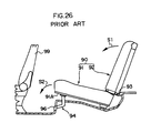
- a conventional rear seat apparatus for a vehicle which is disposed on the elevated rear portion of a vehicle floor, has a structure disclosed, for example, in Japanese Patent Application Laid-Open (JP-A) No. 3-189245.
- a rear seat 90 is composed of a seat cushion 91 and a seat back 92.
- the seat back 92 can swing toward the front of a vehicle (in the direction of arrow S1 in FIG. 26), pivoting on a first hinge 93.
- the seat cushion 91 is connected at a front bottom portion 91A thereof to a vehicle floor 96 by means of an L-shaped link arm 94, thereby allowing it to swing toward the front of the vehicle (in the direction of arrow S2 in FIG. 26).
- a rotary slide mechanism allows at least a rear seat cushion of a rear seat disposed on a rear elevated portion of the floor of the vehicle, to swing by approximately 90 degrees toward the front of the vehicle and then to slide downward into an upright state.
- the front portion of the rear seat cushion is held on a front lower-level portion of the floor of the vehicle, thereby reliably preventing the seat cushion from moving toward the front of the vehicle.
- the rotary slide mechanism also allows the rear seat cushion to swing by approximately 180 degrees toward the front of the vehicle so that the rear seat cushion is overturned.
- the seat cushion can move at all times due to use of a rotary slide mechanism. Therefore, when the rear seat cushion is swung toward the front of the vehicle, the rear seat cushion tends to move downward (toward the center of rotational motion) due to the structure of the rotary slide mechanism. Accordingly, in the process of swinging the rear seat cushion by approximately 180 degrees toward the front of the vehicle in order to bring it into the overturned state, when the rear seat cushion is swung by approximately 90 degrees toward the front of the vehicle, a user must hold the rear seat cushion to prevent the rear seat cushion from sliding downward. This is disadvantageous to the maneuverability of the rear seat cushion.
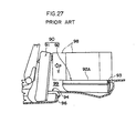
- a rear seat apparatus in accordance with the preamble of new claim 1 is known from US 4,699,418.
- This known rear seat apparatus can be folded as a whole towards the front of the vehicle.
- this rear seat apparatus can be folded into two positions. In a first position, the rear seat apparatus is brought into an upright position and deposited directly in front of the rear elevated portion of the vehicle floor. In this first position, a space remains below the front portion of the rear seat cushion and a lower-level portion in front of the rear elevated portion of the vehicle. In a second position, a front seat is brought forward and the rear seat apparatus is brought forward into a horizontal position coplanar with a rear elevated portion (24).
- a single set of rigid unibody links forming a connection mechanism is used to facilitate both positions.
- a first unibody link is connected to the base of the vehicle at a hinge, supports a femur portion of the rear seat at an arm extension and is connected to a second link at a distal end.
- a third unibody link is also connected to the vehicle base at a pivot and to femur support at a pivot.
- a back support is brought forward approximately ninety degrees, about the pivot, to rest atop the femur support.
- the combination is circularly pivoted around the hinge towards the front of the vehicle so as to come to a halt by the blocking action of a third link resting atop the vehicle base.
- the combined back and femur support is lifted upward, from the vehicle floor, and linearly brought forward, pivoting around the hinge so as to rest coplanar with the vehicle floor and behind the front seat.
- the rear surface of the back support is reinforced to protect the front seat from any forward moving cargo accommodated in the rear of the vehicle.
- EP 0022691 A1 discloses a rear seat apparatus having a rear seat back which is allowed to be folded onto a rear seat cushion and at the same time to be slid a predetermined distance toward the front of the vehicle along with the rear seat cushion. The rear seat apparatus is then allowed to be rotated around a hinge member to take an upright position in which the rear seat cushion obviously is positioned a distance in front of a front lower-level portion in front of a rear elevated portion of the vehicle floor.
- An object of the present invention is to provide a rear seat apparatus for a vehicle capable of providing a spacious luggage room with a flat floor.
- a rear seat apparatus for a vehicle disposed on a rear elevated portion of a stepped floor of the vehicle and allowing at least a rear seat cushion, which is a portion of the rear seat apparatus, to swing toward the front of the vehicle from a horizontal seating state, in which a passenger may sit on the rear seat cushion.
- This rear seat apparatus includes a connection mechanism which connects the rear seat cushion to the rear elevated portion of the floor so as to allow the rear seat cushion to be moved between its seating state and its upright state or overturned state. That is, the connection mechanism allows the rear seat cushion to be moved by approximately 90 degrees from the seating state toward the front of the vehicle and then slide downward so that the rear seat cushion is brought into the upright state.
- connection mechanism In the upright state, the front portion of the rear seat cushion is held on a front lower-level portion of the floor of the vehicle.
- the connection mechanism also allows the rear seat cushion to be moved by approximately 180 degrees from the seating state toward the front of the vehicle so as to be brought into an overturned state.
- the rear seat cushion swings by approximately 90 degrees from the seating state toward the front of the vehicle and then slides downward so that the rear seat cushion is brought into the upright state.
- the rear seat cushion also swings by approximately 180 degrees from the seating state toward the front of the vehicle so that it is overturned to enter the overturned state.
- the seat layout can be modified according to how a passenger is seated.
- the upright state facilitates loading/unloading an article over the upright rear seat cushion from the front seat side.
- connection mechanism is a rotary slide mechanism disposed at the floor and the rear seat cushion.
- the rotary slide mechanism is composed of a rail mounted to the rear seat cushion, a lower plate mounted on the floor, a rail guide plate for guiding the rail, and connection means for pivotably connecting the front end portion of the rail guide plate with the front end portion of the lower plate.
- connection mechanism allows the rear seat cushion to swing by approximately 90 degrees from the seating state toward the front of the vehicle and then slide downward so that the rear seat cushion is brought into the upright state.
- the connection mechanism also allows the rear seat cushion to swing by approximately 180 degrees from the seating state toward the front of the vehicle so that it is overturned to enter the overturned state.
- a rear seat back is hinged to the rear seat cushion.
- the rear seat back can be folded onto the rear seat cushion, or can, together with the rear seat cushion, be brought into the upright state or the overturned state.
- the hinge allows the rear seat back to be folded onto the rear seat cushion from the normal upright state and to, together with the rear seat cushion, be brought into the upright state or the overturned state while the folded state being maintained.
- diversified seat layouts are available.
- the rear seat back is hinged to the vehicle body.
- the rear seat back can be folded onto the rear portion of the floor when the rear seat cushion is in the upright state or the overturned state.
- the hinge allows the rear seat back to be folded onto the rear portion of the floor from the normal upright state when the rear seat cushion is in the upright state or the overturned state.
- diversified seat layouts are available.
- changeover means is provided for selectively hinging the rear seat back to one of the rear seat cushion and the body of the vehicle.
- the changeover means allows the rear seat back to be selectively hinged to one of the rear seat cushion and the body of the vehicle.
- diversified seat layouts are available.
- the rear seat back is divided into a right divisional portion and a left divisional portion, and the changeover means allows these portions to swing independently of each other.
- the rotary slide mechanism has second connection means for pivotably connecting the rear end portion of the rail guide plate and the front end portion of the rail.
- the rotary slide mechanism allows the rear seat cushion to be swung by approximately 90 degrees from the seating state toward the front of the vehicle. Subsequently, the rear seat cushion is lifted upward.
- the second connection means allows the lifted rear seat cushion to be swung by approximately another 90 degrees toward the front of the vehicle.
- one end of the overturned rear seat cushion is supported by a headrest inserted into a guide portion for insertion of a headrest stay provided at the lower portion of a front seat.
- one end of the overturned seat cushion is supported by the headrest inserted into the guide portion for insertion of a headrest stay provided at the lower portion of the front seat.
- a guide portion for insertion of a headrest stay is provided at the rear end portion of the rear seat cushion as well as at the upper portion of the rear seat back.
- the headrest inserted into the guide portions provided at the rear end portion of the rear seat cushion as well as at the upper portion of the rear seat back. Since the two guide portions are provided, a strength of holding the headrest increases accordingly.
- the guide portions and the headrest inserted thereinto function as a simple lock for the overturned rear seat cushion and the rear seat back. Also, diversified seat layouts are available.
- the rear surface of the headrest has a shape corresponding to the shape of the rear surface of a front seat back.
- the rear surface of the headrest inserted into the guide portion for insertion of a headrest stay contacts closely the front seat back, thereby providing a spacious luggage room behind the front seat.
- the rail and the rail guide plate has a substantially U-shaped cross-section whose opening faces downward when the rear seat cushion is in the seating state. Both end portions of the rail, which define the opening, are bent upward so as to project upward beyond bottom ends of the sliding portion of the rail guide plate, thereby forming respective bent portions such that the rail guide plate is slidably housed within the rail.
- a protector is temporarily attached to each of widthwise peripheral surfaces of said rail.
- the protectors are sandwiched between the rail and a seat frame together with a seat covering for covering a cushion pad formed integrally by foaming with the seat frame.
- the rail is fixed to the seat frame by fixing means.
- the protector can be fixed reliably to the rail, and the seat facing can also be mounted reliably. Further, the protector protects the rail.
- the front wall of the protector restricts the movement of the front end of the rail.
- the front wall of the protector prevents grease from leaking out from the front end portion of the rail.
- a rotary slide mechanism is provided so as to connect the rear seat cushion and the rear portion of the floor.
- the rotary slide mechanism has stopper means for preventing the rear seat cushion from sliding downward when it is swung by approximately 90 degrees, and canceling means for canceling the prevention of sliding of the rear seat cushion so that it can slide downward.
- the rotary slide mechanism in the rear seat apparatus for a vehicle according to the fourteenth aspect, includes a rail and an upper plate which are both attached to the rear seat cushion, a lower plate attached onto the floor, connection means for pivotably connecting a front end portion of the upper plate and a front end portion of the lower plate, an upper plate cover, and two lower plate covers.
- the upper and lower plate covers cover a hinge portion which is located in a vicinity of the connection means and at which the upper plate and the lower plate are hinged together.
- the canceling means is a chamfered portion provided on each of the two lower plate covers.
- the stopper means is an operating portion which is provided on one of the two lower plate covers so as to provide relative rotation between the two lower plate covers.
- the chamfered portions of both lower plate covers are aligned with each other.
- the rear seat cushion is swung by approximately 90 degrees toward the front of the vehicle is this state, the rear seat cushion can slide downward.
- the lower plate cover is rotated using the operating portion such that the chamfered portions of both lower plate covers are shifted from each other, the rear seat cushion is prevented from sliding downward when the rear seat cushion is swung by approximately 90 degrees toward the front of the vehicle.
- the stopper and canceling means are simple in structure and facilitate the handling of the rear seat cushion when it is being swung toward the front of the vehicle.
- the upper plate cover and the two lower plate covers prevent the legs of a passenger from abutting directly the hinge portion of the rotary slide mechanism.
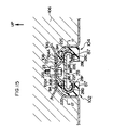
- arrow FR indicates the forward direction of the vehicle
- arrow UP indicates the upward direction of the vehicle
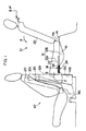
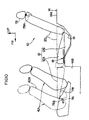
- a rear seat cushion 12 of a rear seat 10 of the first embodiment is disposed on an elevated rear floor surface 14A of a floor 14, which has a stepped portion between its front portion and the elevated rear floor surface 14A.
- the rear seat cushion 12 is divided into a rear seat cushion main body portion 12A located above the floor surface 14A and a rear seat cushion divisional portion 12B located below the floor surface 14A such that these upper and lower divisional portions can be separated from each other.
- the rear seat cushion main body portion 12A is mounted on the front end portion of the floor surface 14A via a rotary slide mechanism 18.
- the rotary slide mechanism 18 allows the rear seat cushion main body portion 12A to swing by approximately 90 degrees toward the front of the vehicle and then to slide downward so that the rear seat cushion is brought into the upright state (illustrated by the dot-and-dash line in FIG. 1).
- the rear seat cushion divisional portion 12B remains in a depression 16 formed in the floor surface 14A.
- a rear seat back 20 is mounted via an unillustrated hinge portion to the rear portion of the rear seat cushion main body portion 12A such that it can swing forward (in the direction of arrow A in FIG. 1).
- the rear seat cushion main body portion 12A when with the rear seat back 20 folded toward the front of the vehicle, the rear seat cushion main body portion 12A is raised upright, the rear seat cushion divisional portion 12B remains in the depression 16 formed in the floor surface 14A, thereby providing a flat surface for carrying an article thereon.
- the rear surface of the rear seat cushion main body portion 12A in its upright state is flat, a relatively large space is provided for housing an article therein.
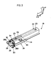
- the rotary slide mechanism 18 extending in the longitudinal direction of the vehicle is disposed at the front portion of the bottom surface of each of the right and left rear seat cushion bodies 12A such that it is located off a normal seating zone, for example, in the vicinity of the right and left ends of each rear seat cushion main body portion 12A.
- the rotary slide mechanism 18 is composed of a rail 22, which is mounted to the bottom portion of the rear seat cushion main body portion 12A, and a hinge portion 24, which is mounted onto the floor 14.
- the rail 22 has a pair of front and rear mounting holes 23 formed therein.
- the rail 22 extending in the longitudinal direction of the vehicle is fixed to the bottom portion of the rear seat cushion main body portion 12A using unillustrated bolts inserted into the mounting holes 23.
- the hinge portion 24 is composed of a pin 26 as connection means, an upper plate 28, and a lower plate 30.
- the axis of the pin 26 is located in the same surface as the floor surface 14A and extends in the widthwise direction of the vehicle.
- the rail 22 is slidably engaged with the upper plate 28.
- the front end portion of the upper plate 28 and that of the lower plate 30 are rotatably connected together by means of the pin 26, thereby allowing the upper plate 28 to swing about the pin 26 with respect to the lower plate 30.
- the lower plate 30 is fixed onto the floor 14 using bolts 34, which are received in corresponding through-holes 32 formed in the upper plate 28.
- the hinge portion 24 allows the rear seat cushion main body portion 12A to swing from the position illustrated by the solid line in FIG. 1 to the position illustrated by the two dots-and-dash line.
- the rail 22 fixed to the rear seat cushion main body portion 12A can slide along a pair of right and left channels 28A and 28B (FIG. 3) provided on the upper plate 28.
- the rear seat cushion main body portion 12A can slide down in the direction of arrow B in FIG. 1 to the position illustrated by the dot-and-dash line.
- a front seat 42 is moved toward the front of the vehicle from the position illustrated by the solid line to the position illustrated by the dot-and-dash line.
- the rear seat cushion main body portion 12A and the rear seat back 20 in the normal seating state are folded together by folding the rear seat back 20 onto the rear seat cushion main body portion 12A, and the folded rear seat cushion main body portion 12A and the rear seat back 20 are swung by approximately 180 degrees toward the front of the vehicle, thereby entering the overturned state illustrated by the dot-and-dash line.
- the rotary slide mechanism 18 allows the above-described movement.
- the rear seat back 20 is supported from underneath by a projecting portion 14C formed on the floor 14.
- a frame 36 formed by bending a pipe into a U-like shape is provided along the bottom peripheral portion of the rear seat cushion main body portion 12A.
- the frame 36 is raised together with the rear seat cushion main body portion 12A.
- a webbing 38 is provided between leg portions 36A and 36B of the frame 36 such that it extends in the widthwise direction of the vehicle.
- an elastic pad 40 is inserted between the webbing 38 and each of the legs 36A and 36B of the frame 36, thereby tensing the webbing 38 by its elastic force in the normal state.
- the rotary slide mechanism 18 attached to the bottom surface of the rear seat cushion main body portion 12A allows the rear seat cushion main body portion 12A with the rear seat back 20 folded thereonto to swing by approximately 90 degrees toward the front of the vehicle so as to enter the upright state and then allows them to slide downward from the position illustrated by the two dots-and-dash line in FIG. 1 to the position of the upright state (illustrated by the dot-and-dash line in FIG. 1).
- the rear seat cushion main body portion 12A and the rear seat back 20 are held at the relatively low position, thereby facilitating loading/unloading an article from the front seat side.
- a relatively large luggage space is provided which has a flat floor extending continuously from the bottom surface 12C of the rear seat cushion main body portion 12A toward the rear portion of the floor surface 14A.
- the rear seat apparatus for a vehicle allows diversified seat layouts in accordance with the state of seating of passengers as well as the number of passengers.
- guide portions 76 and 77 for insertion of a headrest stay may be provided on the rear seat cushion main body portion 12A and the rear seat back 20, respectively, such that the guide portions 76 and 77 are positioned in the vicinity of the lower end portion of a front seat back 42A of the front seat 42 when the rear seat cushion main body portion 12A and the rear seat back 20 are in the overturned state.
- Stays 78A of a headrest 78 are inserted into the guide portions 76 and 77.
- the headrest 78 when an article moves forward due to the vehicle receiving an impact from its front end, the headrest 78 serves as a stopper against the article. Also, the headrest 78 can be held behind the front seat 42. By inserting the stays 78A of the headrest 78 into the guide portions 76 and 77, the rear seat cushion main body portion 12A and the rear seat back 20 can be locked together in a simple manner.
- the headrest 78 By making a rear surface 78B of the headrest 78, which does not contact a passenger's head, correspond in profile to the rear surface of the front seat back 42A of the front seat 42, the headrest 78 contacts closely the front seat back 42A. This allows the headrest 78 to be disposed more frontward, thereby providing a larger luggage room.
- each guide portions 76 functions as a fulcrum, and only a reaction force acts on each guide portions 77 with a bending moment being canceled. Accordingly, the guide portions 76 and 77 require less reinforcement.
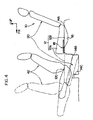
- FIGS. 6 to 9 A second embodiment of a rear seat apparatus for a vehicle of the present invention will now be described with reference to FIGS. 6 to 9.
- the rear seat back 20 in the rear seat apparatus according to the second embodiment, in the normal seating state, the rear seat back 20 has its center P1 of rotation provided at a bracket (not shown) fixed on the floor 14, so that the rear seat back 20 swings towards the front of the vehicle (in the direction of arrow A in FIG. 6) to move to the position illustrated by the three dots-and-dash line in FIG. 6.
- the rear seat cushion main body portion 12A, together with the rear seat back 20 is raised up, the rear seat cushion main body portion 12A and the rear seat back 20 are swung together while the rear seat back 20 is supported by center P2 of rotation provided at a hinge bracket 44 fixed on the rear seat cushion main body portion 12A.
- the rear seat cushion main body portion 12A and the rear seat back 20 slide downward so that their front portions are held on the front lower-level portion of the floor of the vehicle, thus entering the upright state (illustrated by the dot-and-dash line in FIG. 6).
- the rear seat cushion main body portion 12A and the rear seat back 20 are swung by approximately 180 degrees to enter the overturned state (illustrated by the two dots-and-dash line in FIG. 6).
- the rear seat back 20 is divided into a left rear seat back 20A which is located behind a front passenger's seat, and a right rear seat back 20B, which is located behind a driver's seat. This prevents interference with an unillustrated tunnel portion of the floor when the rear seat cushion main body 12A of a left rear seat cushion located is swung by approximately 180 degrees toward the front of the vehicle.
- Lower pins 45 and 46 are provided in the left rear seat back 20A and in the right rear seat back 20B, respectively, and are located at the outer sides of the rear seat backs 20A and 20B, respectively, in the widthwise direction of the vehicle. In the normal seating state, the lower pins 45 and 46 are inserted into respective bearing portions provided on a body 48.
- a lower pin 50 is provided in the left rear seat back 20A and is located at the inner side of the rear seat back 20A in the widthwise direction of the vehicle. The lower pin 50 is inserted into a bearing portion 52B of a floor hinge bracket 52 fixed to the floor 14.
- the floor hinge bracket 52 is fixed to the floor 14 using bolts 53.
- the bearing portion 52B is a tubular member projecting from the floor hinge bracket 52.
- the bearing portion 52B is inserted into the inner side (in the widthwise direction of the vehicle) of the right rear seat back 20B, thereby serving as the axis of rotation of the rear seat back 20B.
- a knob 54 serving as changeover means is provided on a rear surface 20C of the left rear seat back 20A.
- a guide 56 formed integrally with the knob 54 has upper and lower elongated holes 58 and 60, and a protrusion 64 provided on the lower pin 45 and a protrusion provided on the upper pin 66 are engaged with the elongated holes 58 and 60 of the guide 56, respectively.
- the lower pin 50 which is disposed at the inner side (in the widthwise direction of the vehicle) of the left rear seat back 20A, is connected to the upper pin 66 through a link 70 or the like, while an upper pin 68 is connected to the lower pin 45 through the link 70. Accordingly, linking o the movement of the upper and lower pins 66 and 45, the lower pin 50 disengages from the bearing portion 52B, and the upper pin 68 is inserted into the seat hinge bracket 44. As a result of this linked operation, the center of rotation of the rear seat back 20 changes from P1 to P2 in FIG. 6.
- the rear seat back 20 in the normal seating state, has its center P1 of rotation at the bracket (not shown) fixed on the floor 14.
- the rear seat back 20 can be swung toward the front of the vehicle (in the direction of arrow A in FIG. 6) to be folded onto the rear seat cushion main body portion 12A (as illustrated by the three dots-and-dash line in FIG. 6).
- the seat layout can be modified as follows. While the rear seat back 20 is held in its seat sate, only the rear seat cushion main body portion 12A on the right side can be swung by approximately 90 degrees and further be slid downward so that the rear seat cushion is brought into the upright state. Alternatively, only the rear seat cushion main body portion 12A on the left side can also be brought into the upright state or can be swung by approximately 180 degrees into the overturned state.
- the rear seat back 20A When P2 is chosen as the center of rotation for the rear seat back 20, the rear seat back 20A, together with the rear seat cushion main body 12A, can be swung by approximately 180 degrees toward the front of the vehicle, thereby entering the overturned state (illustrated by the two dots-and-dash line in FIG. 6).
- This provides a relatively large space for housing an article which has a flat floor extending continuously from the bottom surface 12C of the rear seat cushion main body portion 12A toward the rear portion of the floor surface 14A.
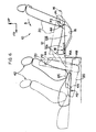
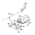
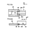
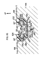
- FIGS. 10 to 13 A third embodiment of a rear seat apparatus for a vehicle of the present invention will now be described with reference to FIGS. 10 to 13.
- the overturned rear seat cushion main body portion 12A becomes substantially flush with the rear seat back 20 folded toward the front of the vehicle as illustrated by the dot-and-dash line.
- the front seat 42 can be moved toward the front of the vehicle from a position illustrated by the solid line to a position illustrated by the dot-and-dash line, and the stays 78A of the headrest 78 can be inserted into the head rest stay guide portions 76 provided at the lower portion of the front seat back 42A.
- the head rest 78 fixed into the guide portions 76 supports the front end portion of the overturned rear seat cushion main body portion 12A.
- the guide portions 76 may be provided at the seat cushion of the front seat 42.
- a protrusion 80 is provided at the rear portion of each of the channel portions 28A and 28B of the upper plate 28 such that the protrusions 80 face each other so as to decrease the distacne between the channel portions 28A and 28B at the position of the protrusions 80.
- a pin 82 is provided at the front end portion of the rail 22 such that it passes through the front end portion in the widthwise direction of the vehicle.
- the pin 82 has a length greather than the distance between the facing protrusions 80 and serves as second connection means.
- Flange portions 22A and 22B of the rail 22 are partially cut away at the position corresponding to the pin 82.
- the rear seat cushion main body portion 12A is swung by approximately 90 degrees from the position of the normal seating state (illustrated by the two dots-and-dash line in FIG. 13) to a position illustrated by the dot-and-dash line in FIG. 13. Subsequently, the rear seat cushion main body portion 12A is lifted toward the upper portion of the vehicle to a position illustrated by the solid line in FIG. 13 so as to slide the rail 22 up to the rear end of the upper plate 28. From this lifted position, the seat cushion main body portion 12A is swung by approximately another 90 degrees toward the front of the vehicle to the position illustrated by the three dots-and-dash line in FIG. 13 (overturned state).
- This provides a relatively large luggage space having a flat floor which extends continuously from the bottom surface 12C of the rear seat cushion main body portion 12A to the rear portion of the floor surface 14A via the rear surface 20C of the forwardly folded rear seat back 20 (positioned as illustrated by the dot-and-dash line in FIG. 13).
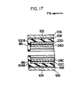
- FIGS. 14 to 18 A fourth embodiment of a rear seat apparatus for a vehicle of the present invention will now be described with reference to FIGS. 14 to 18.
- each of the rail 22 and the upper plate 28 has a substantially U-shaped cross section as viewed in the longitudinal direction thereof such that the opening of the U-shape faces downward in the normal seating state (the rear seat cushion main body portion 12A is not swung, as illustrated by the two dots-and-dash line in FIG. 18).
- both side portions of the rail 22 in the widthwise direction of the rail 22 project outward to form guide portions 22C and 22D.
- These guide portions 22C and 22D house slidably sliding portions 28C and 28D of the upper plate 28, which sliding portions 28C and 28D project outward in a manner similar to that of the guide portions 22C and 22D.
- Both end portions of the rail 22, which define the opening of the U-shape, are further bent upward to form bend portions 22E and 22F. These bend portions 22E and 22F project upward beyond the corresponding bottom end portions 28E and 28F of the sliding portions 28C and 28D of the upper plate 28.
- Grease 86 is applied to a sliding surface 84 between the rail 22 and the upper plate 28.
- the sliding surface 84 is a sliding surface which becomes effective in the normal seating state (the rear seat cushion main body portion 12A is not swung).
- the grease 86 is also applied to a sliding surface 87 between the rail 22 and the upper plate 28.
- the sliding surface 87 is a sliding surface which becomes effective in the overturned state after being swung by approximately 180 degrees (the rear seat cushion main body portion 12A is swung by approximately 180 degrees as illustrated by the solid line in FIG. 18).
- a mounting portion 22G projecting upward and having a trapezoidal cross-section is formed on the rail 22 at the position opposite to the opening of the rail 22.
- the rail 22 is fixed to the seat frame 100 using bolts 89 which are inserted as fixing means through mounting holes 23 formed in the mounting portion 22G.
- Protectors 102 and 104 are temporarily attached to the outer surfaces of both side portions of the rail 22 in the widthwise direction of the rail 22 so as to cover the guide portions 22D and 22C, respectively. Upper portions 102A and 104A of the protectors 102 and 104, respectively, together with seat facing 108, are held between the guide portions 22C and 22D of the rail 22 and the seat frame 100.
- the seat facing 108 covers the surface of a cushion pad 106, which is foamed and integrated with the seat frame 100.
- front walls 102B and 104B are formed at the front end portions of the protectors 102 and 104, respectively.
- the front walls 102B and 104B of the protectors 102 and 104 restrict a longitudinal movement of the front end portions of the guide portions 22C and 22D of the rail 22.
- the grease 86 is applied to the sliding surface 84 between the rail 22 and the upper plate 28 which becomes effective in the normal seating state (the rear seat cushion main body portion 12A is not swung) and to the sliding surface 87 between the rail 22 and the upper plate 28 which becomes effective in the overturned state (the rear seat cushion main body portion 12A is swung by approximately 180 degrees).
- the grease 86 is applied along the inner surfaces of the guide portions 22C and 22D of the rail 22. Further, the bend portions 22E and 22F formed at both end portions of the rail 22 project upward beyond the corresponding bottom end portions 28E and 28F of the sliding portions 28C and 28D of the upper plate 28. As a result, the grease 86 is less likely to leak out from the rail 22.
- the front end portions of the guide portions 22C and 22D of the rail 22 are closed by the front walls 102B and 104B of the protectors 102 and 104, thereby preventing the grease 86 from leaking out from the front end portions of the rail 22.
- the upper portions 102A and 104A of the protectors 102 and 104, together with the seat facing 108 which covers the surface of the cushion pad 106 foamed and integrated with the seat frame 100, are held between the guide portions 22C and 22D of the rail 22 and the seat frame 100.
- the protectors 102 and 104 can be reliably fixed onto the rail 22, and the seat facing 108 can also be reliably fixed in place. Further, the protectors 102 and 104 protect the rail 22.
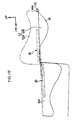
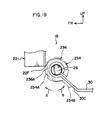
- FIGS. 19 to 23 A fifth embodiment of a rear seat apparatus for a vehicle of the present invention will now be described with reference to FIGS. 19 to 23.
- arrow FR denotes the direction toward the front of the vehicle
- arrow IN denotes the direction toward the center of the width of the vehicle
- arrow UP denotes the direction toward the top of the vehicle.
- a rear seat 210 of the fifth embodiment is divided in the widthwise direction of the vehicle at the ratio of approximately 4:2:4 into a left rear seat 210A, a center rear seat 210B, and a right rear seat 210C.
- corresponding rear seat cushions 212A, 212B, and 212C of the rear seats 210A, 210B, and 210C are disposed on the floor surface 14A of the elevated rear portion of the stepped floor 14.
- the right rear seat cushion 212C of the right rear seat 210C is mounted on the front end portion of the floor surface 14A via the rotary slide mechanism 18.
- the rotary slide mechanism 18 allows the right rear seat cushion 212C to swing by approximately 90 degrees toward the front of the vehicle (as illustrated by the two dots-and-dash line in FIG. 23) and then to slide downward such that the front portion of the right rear seat cushion 212C is held on the floor surface 14D of the front lower-level portion of the floor, thus entering the upright state (as illustrated by the dot-and-dash line in FIG. 23).
- the rotary slide mechanism 18 also allows the right rear seat cushion 212C to swing by approximately 180 degrees toward the front of the vehicle, thus entering the overturned state (as illustrated by the solid line in FIG. 23).
- the left rear seat cushion 212A of the left rear seat 210A is also mounted on the front end portion of the floor surface 14A via the rotary slide mechanism 18.
- the rotary slide mechanism 18 allows the left rear seat cushion 212A to be brought into the upright state or the overturned state.
- Each of the rear seat backs 220A, 220B, and 22C is mounted via an unillustrated hinge portion to the rear portion of each of the rear seat cushions 212A, 212B, and 212C such that it can swing forward.
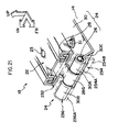
- the rotary slide mechanism 18 is composed of a rail 22, which is mounted to the bottom portion of each of the rear seat cushions 212A, 212B, and 212C, and a hinge portion 24, which is mounted onto the floor 14.
- a plurality of mounting holes 23 are formed in the rail 22. Using bolts (not shown) inserted into the mounting holes 23, the rail 22 is fixed onto each of the rear seat cushions 212A, 212B, and 212C such that it extends in the longitudinal direction of the vehicle.
- the hinge portion 24 has a pin 26 serving as connection means and extending in the widthwise direction of the vehicle, an upper plate 28 to which the rail 22 is slidably mounted, and a lower plate 30.
- a cylindrically formed front end portion 28G of the upper plate 28 is connected via the pin 26 with a pair of cylindrically formed front end portions 30A and 30B of the lower plate 30. Accordingly, the upper plate 28 is pivotable about the pin 26 with respect to the lower plate 30.
- Unillustrated mounting holes are formed in the lower plate 30.
- the lower plate 30 is fixed onto the floor 14 using bolts 31 inserted through the mounting holes.
- the rear portion of the rear seat cushion 212 is locked to the floor 14.
- the rear seat cushion 212 is slidable when the rear seat cushion 212 is used in the normal state.
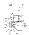
- the front end portion 28G and its periphery of the upper plate 28 is covered with an upper plate cover 232 illustrated by the two dots-and-dash line.
- the front end portion 30A of the lower plate 30 located outside in the widthwise direction of the vehicle is covered with a lower plate cover outer 234 illustrated by the two dots-and-dash line in FIG. 22 and being C-shaped as viewed from its side.
- the lower plate cover outer 234 serves as stopper means.
- the front end portion 30B of the lower plate 30 located inside in the widthwise direction of the vehicle is covered with a lower plate cover inner 236 illustrated by the two dots-and-dash line in FIG. 22 and being C-shaped as viewed from its side.
- the lower plate cover inner 236 also serves as stopper means.
- the diameter of the lower plate cover outer 234 is slightly smaller than that of the lower plate cover inner 236.
- the lower plate cover inner 236 is fixed onto the front end portion 30B of the lower plate 30.
- the lower plate cover inner 236 has a chamfered portion 236A formed at the circumferential front portion thereof.
- the chamfered portion 236A serves as canceling means.
- the lower plate cover outer 234 is attached to the front end portion 30A of the lower plate 30 such that it is pivotable about the pin 26 clockwise (in the direction of arrow A in FIG. 19) and counterclockwise (in the direction of arrow B in FIG. 19).
- Part of the circumference of the lower plate cover outer 234 is chamfered to form a chamfered portion 234A serving as canceling means.
- a lever portion 234B serving as an operating portion extends from the lower end portion of the lower plate cover outer 234 outwardly in the radial direction of the lower plate cover outer 234.
- the position of the chamfered portion 234A of the lower plate cover outer 234 corresponds to that of the chamfered portion 236A of the lower plate cover inner 236.
- the rail 22 when the rail 22 is swung by approximately 90 degrees toward the front of the vehicle from the normal state of use illustrated by the solid line in FIG. 20 to the position illustrated by the two dots-and-dash line in FIG. 20, the rail 22 can slide downward (in the direction of arrow C) along the chamfered portion 234A of the lower plate cover outer 234 as well as the chamfered portion 236A of the lower plate cover inner 236.
- the center rear seat 210B is mounted on the front end portion of the floor surface 14A via a rotary slide mechanism 19.
- the rotary slide mechanism 19 allows the rear seat cushion 212 to swing by approximately 90 degrees toward the front of the vehicle and then to slide downward so that the front portion of the rear seat cushion 212 is held on a floor tunnel portion 240, thus entering the upright state (as illustrated by the solid line in FIG. 23).
- the level of the floor tunnel portion 240 is lower than the elevated rear portion of the stepped floor by half the height of the eleveted rear portion of the floor from the unelevated front portion thereof.
- the rotary slide mechanism 19 is a modified rotary slide mechanism 18 in which both front end portions 30A and 30B of the lower plate 30 are provided with the lower plate cover inner 236.
- the rotary slide mechanisms 18 allow the corresponding rear seat cushions 212A and 212C of the left rear seat 210A and the right rear seat 210C to swing toward the front of the vehicle.
- the position of the chamfered portion 234A of the lower plate cover outer 234 corresponds to that of the chamfered portion 236A of the lower plate cover inner 236.
- the right and left rear seat cushions 212C and 212A are swung by approximately 90 degrees toward the front of the vehicle, they can further slide downward to be held at the position (upright state) illustrated by the dot-and-dash line in FIG. 23.
- the right and left rear seat cushions 212C and 212A and the right and left rear seat backs 220C and 220A are held at a relatively low position, thereby facilitating loading/unloading an article from the front seat side.
- the corresponding slide mechanism 18 acts as follows.
- the lower plate cover outer 234 is first turned by operating the lever portion 234B of the lower plate cover outer 234 until the lever portion 234B abuts the slope surface 30C of the lower plate 30, so that the chamfered portion 234A of the lower plate cover outer 234 moves in the direction of arrow B away from the position corresponding to the position of the chamfered portion 236A of the lower plate cover inner 236.
- the front end portion 22F of the rail 22 abuts the circumferential portion of the lower plate cover outer 234, thereby preventing the rail 22 from moving downward.
- the rear seat cushions 212A and 212C it is possible to swing the rear seat cushions 212A and 212C while preventing them from sliding toward the center of swing, when the rear seat cushions 212A and 212C are swung by approximately 180 degrees toward the front of the vehicle. That is, when the lever portion 234B is abutted against the slope surface 30C of the lower plate 30, the chamfered portion 234A of the lower plate cover outer 234 moves in the direction of arrow B away from the position corresponding to the position of the chamfered portion 236A of the lower plate cover inner 236.
- FIG. 24 A sixth embodiment of a rear seat apparatus for a vehicle of the present invention will now be described with reference to FIG. 24.
- a rear seat 250 of the sixth embodiment is divided in the widthwise direction of the vehicle at the ratio of approximately 4:6 into a left rear seat 250A and a right rear seat 250B.
- a left rear seat cushion 252A of the left rear seat 250A is mounted on the front end portion of the floor surface 14A via the rotary slide mechanism 18 of the fifth embodiment.
- the rotary slide mechanism 18 allows the left rear seat cushion 252A to swing by approximately 90 degrees toward the front of the vehicle and then to slide downward so that the front portion of the left rear seat cushion 252A is held on the floor surface 14D of the front lower-level portion of the floor, thus entering the upright state (as illustrated by the solid line in FIG. 24).
- the rotary slide mechanism 18 also allows the left rear seat cushion 252A to swing by approximately 180 degrees toward the front of the vehicle, thus entering the overturned state (as illustrated by the two dots-and-dash line in FIG. 24).
- a right rear seat cushion 252B of the right rear seat 250B is mounted on the front end portion of the floor surface 14A via the rotary slide mechanism 19 of the fifth embodiment.
- the rotary slide mechanism 19 allows the right rear seat cushion 252B to swing by approximately 90 degrees toward the front of the vehicle and then to slide downward so that the front portion of the rear seat cushion is held on a floor tunnel portion 240, thus entering the upright state (as illustrated by the solid line in FIG. 24).
- the level of the floor tunnel portion 240 is lower than the elevated rear portion of the stepped floor by half the height of the elevated rear portion of the floor from the unelevated front portion thereof.
- Each of the rear seat backs 254A and 254B is mounted via an unillustrated hinge portion to the rear portion of each of the rear seat cushions 252A and 252B such that it can swing forward.
- the left rear seat 250A of the sixth embodiment it is possible to prevent the left rear seat cushion 252A from sliding downward when the left rear seat cushion 252A is swung by approximately 180 degrees toward the front of the vehicle. That is, when the lower plate cover outer 234 is turned in the direction of arrow B by operating the lever portion 234B until the lever portion 234B abuts the slope surface 30C of the lower plate 30, it becomes possible to swing the left rear seat cushion 252A while preventing the left rear seat cushion 252A from sliding toward the center of swing.
- the position of the chamfered portion 234A of the lower plate cover outer 234 and the position of the chamfered portion 236A of the lower plate cover inner 236 are relatively shifted from each other, thereby controlling the downward movement of the left rear seat cushion 252A.
- the structure can be simplified.
- the lower plate cover outer 234 as well as the lower plate cover inner 236 cover the hinge portion 24 of the rotary slide mechanism 18, the hinge portion 24 of the rotary slide mechanism does 18 not directly contact the leg portion of a passenger.
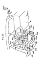
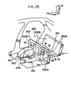
- a seventh embodiment of a rear seat apparatus for a vehicle of the present invention will now be described with reference to FIG. 25.
- a rear seat back 261 is mounted on the floor surface 14A of the elevated rear portion of the floor 14 and is separated from a rear seat cushion 262.
- the rear seat 260 is divided in the widthwise direction of the vehicle at the ratio of approximately 4:6 into a left rear seat 260A and a right rear seat 260B.
- a left rear seat cushion 262A of the left rear seat 260A is mounted on the front end portion of the floor surface 14A via the rotary slide mechanism 18 of the fifth embodiment.
- the rotary slide mechanism 18 allows the left rear seat cushion 262A to swing by approximately 90 degrees toward the front of the vehicle and then to slide downward so that the front portion of the left rear seat cushion 262A is held on the floor surface 14D of the front lower-level portion of the floor, thus entering the upright state (as illustrated by the solid line in FIG. 25).
- the rotary slide mechanism 18 also allows the left rear seat cushion 262A to swing by approximately 180 degrees toward the front of the vehicle, thus entering the overturned state (as illustrated by the two dots-and-dash line in FIG. 25).
- a right rear seat cushion 262B of the right rear seat 260B is mounted on the front end portion of the floor surface 14A via the rotary slide mechanism 19 of the fifth embodiment.
- the rotary slide mechanism 19 allows the right rear seat cushion 262B to swing by approximately 90 degrees toward the front of the vehicle and then to slide downward so that the front portion of the rear seat cushion is held on a floor tunnel portion 240, thus entering the upright state (as illustrated by the solid line in FIG. 25).
- the level of the floor tunnel portion 240 is lower than the elevated rear portion of the stepped floor by half the wall height of the stepped portion of the floor.
- a child seat portion 264 is formed on the right rear cushion 262B of the right rear seat 260B at a position corresponding to the top portion of the floor tunnel portion 240. Through an unillustrated hinge, this child seat portion 264 can be folded onto the seating surface of the right rear seat cushion 262B. Thus, by folding the child seat portion 264 onto the right rear seat cushion 262B as illustrated by the solid line in FIG. 25, the child seat portion 264 can be prevented from interfering with the floor tunnel portion 240.
- the height of the right rear seat cushion 262B in its upright state is set substantially identical to that of the left rear seat cushion 262A in its upright state.
- the left rear seat 260A of the seventh embodiment it is possible to swing the left rear seat cushion 262A while preventing the left rear seat cushion 262A from sliding toward the center of swing, when the left rear seat cushion 262A is swung by approximately 180 degrees toward the front of the vehicle via the slide mechanism 18, when the lower plate cover outer 234 is turned in the direction of arrow B by operating the lever portion 234B until the lever portion 234B abuts the slope surface 30C of the lower plate 30, it becomes possible to swing the left rear seat cushion 262A while preventing the left rear seat cushion 262A from sliding toward the center of swing.
- the position of the chamfered portion 234A of the lower plate cover outer 234 and the position of the chamfered portion 236A of the lower plate cover inner 236 are relatively shifted from each other, thereby controlling the downward movement of the left rear seat cushion 262A.
- the structure can be simplified. Further, since in addition to the upper plate cover 232, the lower plate cover outer 234 as well as the lower plate cover inner 236 cover the hinge portion 24 of the rotary slide mechanism 18, the hinge portion 24 of the rotary slide mechanism 18 does not directly contact the leg portion of a passenger.
Description
Alternatively, the rear seat cushion
Claims (22)
- A rear seat apparatus (10; 210) for a vehicle disposed on a rear elevated portion (14A) of a stepped floor (14) of the vehicle and allowing at least a rear seat cushion (12; 212A, 212B, 212C), which is a portion of the rear seat apparatus (10; 210), to swing toward the front of the vehicle from a horizontal seating state, in which a passenger may sit on the rear seat cushion (12 212A, 212B, 212C), said rear seat apparatus (10; 210) having a connection mechanism (18) connecting said rear seat cushion (12; 212A, 212B, 212C) to the rear elevated portion (14A) of the floor (14) of the vehicle and allowing said rear seat cushion (12; 212A, 212B, 212C) to be moved toward the front of the vehicle, characterised in that:
said connection mechanism (18) allows said rear seat cushion (12; 212A, 212B, 212C) to be moved by approximately 90 degrees toward the front of the vehicle and then to be slid downward so as to be brought into an upright state, in which a front portion of said rear seat cushion (12; 212A, 212B, 212C) is held on a front lower-level portion (14B) in front of said rear elevated portion (14A) of the floor (14) of the vehicle, and also allows said rear seat cushion (12; 212A, 212B, 212C) to be moved by approximately 180 degrees from said seating state toward the front of the vehicle so as to be brought into an overturned state. - A rear seat apparatus (10) for a vehicle according to Claim 1, wherein said connection mechanism (18) is a rotary slide mechanism (18) disposed at the floor (14) of the vehicle and said rear seat cushion (12), and said rotary slide mechanism (18) includes a rail (22) mounted to said rear seat cushion (12), a lower plate (30) mounted on the floor (14), a rail guide plate (28) for guiding said rail (22), and connection means (24) for pivotably connecting a front end portion of said rail guide plate (28) with a front end portion of said lower plate (30).
- A rear seat apparatus (10) for a vehicle according to Claim 2, wherein a rear seat back (20) is hinged to said rear seat cushion (12) such that said rear seat back (20) can be folded onto said rear seat cushion (12), or can, together with said rear seat cushion (12), be brought into said upright state or said overturned state.
- A rear seat apparatus (10) for a vehicle according to Claim 3, wherein a guide portion (76, 77) for insertion of a headrest stay (78A) is provided at a rear end portion of said rear seat cushion (12) as well as at an upper portion of said rear seat back (20), and when said rear seat cushion (12) and said rear seat back (20) are swung together by approximately 180 degrees toward the front of the vehicle to enter said overturned state, a stay (78A) of said headrest (78) is inserted into said guide portions (76, 77).
- A rear seat apparatus (10) for a vehicle according to Claim 4, wherein the rear surface (78B) of said headrest (78) has a shape corresponding to the shape of the rear surface (42A) of a front seat back (42).
- A rear seat apparatus (10) for a vehicle according to Claim 2, wherein a rear seat back (20) is hinged to the vehicle body such that said rear seat back (20) is allowed to be folded onto the rear portion of the floor (14) when said rear seat cushion (12) is in said upright state or said overturned state.
- A rear seat apparatus (10) for a vehicle according to Claim 2, further comprising:
changeover means (44-70) for selectively hinging a rear seat back (20) to one of said rear seat cushion (12) and the body of the vehicle. - A rear seat apparatus (10) for a vehicle according to Claim 7, wherein said rear seat back (20) is divided into a right divisional portion (20B) and a left divisional portion (20A), which are independently swung by said changeover means (44-70).
- A rear seat apparatus (10) for a vehicle according to Claim 2, wherein said rotary slide mechanism (18) has second connection means (80, 82) for pivotably connecting a rear end portion of said rail guide plate (28) and a front end portion of said rail (22).
- A rear seat apparatus (10) for a vehicle according to Claim 9, wherein when said rear seat cushion (12) is in said overturned state, one end of said rear seat cushion (12) is supported by a headrest (78) inserted into a guide portion (76) for insertion of a headrest stay (78A) provided at a lower portion of a front seat (42).
- A rear seat apparatus (10) for a vehicle according to Claim 2, wherein said rail (22) and said rail guide plate (28) have a substantially U-shaped cross-section whose opening faces downward when said rear seat cushion (12) is in said seating state, and both end portions (22E, 22F) of said rail (22), which define said opening, are bent upward so as to project upward beyond bottom ends (28E, 28F) of a sliding portion (28C, 28D) of said rail guide plate (28), thereby forming respective bent portions (22E, 22F) such that said rail guide plate (28) is slidably housed within said rail (22).
- A rear seat apparatus (10) for a vehicle according to Claim 11, wherein a protector (102, 104) is temporarily attached to each of widthwise peripheral surfaces (22C, 22D) of said rail (22), said protectors (102, 104) are sandwiched between said rail (22) and a seat frame (100) together with a seat covering (108) for covering a cushion pad (106) formed integrally by foaming with said seat frame (100), and said rail (22) is fixed to said seat frame (100) by fixing means.
- A rear seat apparatus (10) for a vehicle according to Claim 12, wherein movement of the front end of said rail (22) is restricted by front walls (102B, 104B) of said protectors (102, 104).
- A rear seat apparatus (10) for a vehicle according to Claim 1, wherein a rear seat back (20) is hinged to said rear seat cushion (12) such that said rear seat back (20) can be folded onto said rear seat cushion (12), or can, together with said rear seat cushion (12), be brought into said upright state or said overturned state.
- A rear seat apparatus (10) for a vehicle according to Claim 14, wherein a guide portion (76, 77) for insertion of a headrest stay (78A) is provided at a rear end portion of said rear seat cushion (12) as well as at an upper portion of said rear seat back (20), and when said rear seat cushion (12) and said rear seat back (20) are swung together by approximately 180 degrees toward the front of the vehicle to enter said overturned state, a stay (78A) of said headrest (78) is inserted into said guide portions (76, 77).
- A rear seat apparatus (10) for a vehicle according to Claim 15, wherein the rear surface (78B) of said headrest (78) has a shape corresponding to the shape of the rear surface of a front seat back (42A).
- A rear seat apparatus (10) for a vehicle according to Claim 1, wherein a rear seat back (20) is hinged to the vehicle body such that said rear seat back (20) is allowed to be folded onto the rear portion of the floor (14) when said rear seat cushion (12) is in said upright state or said overturned state.
- A rear seat apparatus (10) for a vehicle according to Claim 1, further comprising:
changeover means (44-70) for selectively hinging a rear seat back (20) to one of said rear seat cushion (12) and the body of the vehicle. - A rear seat apparatus (210) for a vehicle according to claim 1, wherein said connection mechanism (18) is a rotary slide mechanism (18) disposed at the floor (14) of the vehicle and said rear seat cushion (112A, 112B, 112C), with said rotary slide mechanism (18) having stopper means (234, 236) for preventing said rear seat cushion (112A, 112B, 112C) from sliding downward when said rear seat cushion (112A, 112B, 112C) is swung by approximately 90 degrees, and cancelling means (234A, 236A) for cancelling the prevention of sliding of said rear seat cushion (112A, 112B, 112C) so that said rear seat cushion (112A, 112B, 112C) is allowed to slide downward.
- A rear seat apparatus (210) for a vehicle according to Claim 19, wherein said rotary slide mechanism (18) includes a rail (22) and an upper plate (28) which are both attached to said rear seat cushion (112A, 112B, 112C), a lower plate (30) attached onto the floor (14), connection means (24) for pivotably connecting a front end portion (28G) of said upper plate (28) and a front end portion (30A) of said lower plate (30), an upper plate cover (232), and two lower plate covers (234, 236), said upper and lower plate covers (232, 234, 236) covering a hinge portion which is located in a vicinity of said connection means (24) and at which said upper plate (28) and said lower plate (30) are hinged together.
- A rear seat apparatus (10) for a vehicle according to Claim 20, wherein said canceling means (234A, 236A) is a chamfered portion (234A, 236A) provided on each of said two lower plate covers (234, 236).
- A rear seat apparatus (10) for a vehicle according to Claim 20, wherein said stopper means is an operating portion (234B) which is provided on one of said two lower plate covers (234) so as to provide relative rotation between said two lower plate covers (234, 236).
Applications Claiming Priority (9)
| Application Number | Priority Date | Filing Date | Title |
|---|---|---|---|
| JP244875/95 | 1995-09-22 | ||
| JP24487595 | 1995-09-22 | ||
| JP24487595 | 1995-09-22 | ||
| JP33224095 | 1995-12-20 | ||
| JP7332240A JP3036421B2 (en) | 1995-12-20 | 1995-12-20 | Rear seat device for vehicles |
| JP332240/95 | 1995-12-20 | ||
| JP26746/96 | 1996-02-14 | ||
| JP2674696 | 1996-02-14 | ||
| JP8026746A JP3036426B2 (en) | 1995-09-22 | 1996-02-14 | Rear seat device for vehicles |
Publications (3)
| Publication Number | Publication Date |
|---|---|
| EP0769412A2 EP0769412A2 (en) | 1997-04-23 |
| EP0769412A3 EP0769412A3 (en) | 1998-11-11 |
| EP0769412B1 true EP0769412B1 (en) | 2001-10-31 |
Family
ID=27285516
Family Applications (1)
| Application Number | Title | Priority Date | Filing Date |
|---|---|---|---|
| EP96113754A Expired - Lifetime EP0769412B1 (en) | 1995-09-22 | 1996-08-28 | rear seat apparatus for a vehicle |
Country Status (3)
| Country | Link |
|---|---|
| US (1) | US5868450A (en) |
| EP (1) | EP0769412B1 (en) |
| DE (1) | DE69616477T2 (en) |
Families Citing this family (52)
| Publication number | Priority date | Publication date | Assignee | Title |
|---|---|---|---|---|
| DE19740776C1 (en) * | 1997-09-16 | 1998-10-01 | Lear Corp Gmbh & Co Kg | Folding backrest for vehicle rear seat bank |
| JP3773078B2 (en) * | 1997-11-04 | 2006-05-10 | スズキ株式会社 | Seat back support structure |
| FR2775228B1 (en) * | 1998-02-25 | 2000-03-31 | Peugeot | ASSEMBLY OF REMOVABLE BACKREST SEATS OF MOTOR VEHICLE |
| JP4161438B2 (en) * | 1998-12-18 | 2008-10-08 | アイシン精機株式会社 | Vehicle seat device |
| US6386629B1 (en) * | 1999-03-01 | 2002-05-14 | Lear Corporation | Vehicle seat |
| US6250704B1 (en) * | 1999-08-12 | 2001-06-26 | Dura Automotive Systems Inc. | Release mechanism for fold and flip seat assembly |
| GB2356557B (en) | 1999-11-26 | 2003-12-17 | Autoliv Dev | Improvements in or relating to a vehicle seat unit |
| US6817646B2 (en) * | 2002-08-26 | 2004-11-16 | Honda Giken Kogyo Kabushiki Kaisha | Vehicle seat |
| JP2004210113A (en) * | 2002-12-27 | 2004-07-29 | T S Tec Kk | Slide rail of seat for automobile |
| US20040195888A1 (en) * | 2003-04-03 | 2004-10-07 | Johnson Controls Technology Company | Configurable vehicle seat |
| US7159922B2 (en) * | 2003-09-25 | 2007-01-09 | Mazda Motor Corporation | Seat structure for vehicle |
| JP2006151246A (en) * | 2004-11-30 | 2006-06-15 | Johnson Controls Technol Co | Seat structure for vehicle |
| US20060175517A1 (en) * | 2005-02-10 | 2006-08-10 | Syrowik Glenn F | Auto full forward seat adjuster |
| US7128358B2 (en) * | 2005-02-11 | 2006-10-31 | Honda Motor Co., Ltd. | Adjustable collapsible seat assembly |
| DE102012011508A1 (en) * | 2012-06-09 | 2013-12-12 | GM Global Technology Operations LLC (n. d. Gesetzen des Staates Delaware) | Adjustment device for a vehicle seat, vehicle seat, row of seats, vehicle and method for this purpose |
| US9399418B2 (en) | 2013-01-24 | 2016-07-26 | Ford Global Technologies, Llc | Independent cushion extension and thigh support |
| US9415713B2 (en) | 2013-01-24 | 2016-08-16 | Ford Global Technologies, Llc | Flexible seatback system |
| US9902293B2 (en) | 2013-01-24 | 2018-02-27 | Ford Global Technologies, Llc | Independent cushion extension with optimized leg-splay angle |
| US9409504B2 (en) | 2013-01-24 | 2016-08-09 | Ford Global Technologies, Llc | Flexible seatback system |
| US9187012B2 (en) | 2013-12-12 | 2015-11-17 | Ford Global Technologies, Llc | Pivoting and reclining vehicle seating assembly |
| US9315131B2 (en) | 2014-01-23 | 2016-04-19 | Ford Global Technologies, Llc | Suspension seat back and cushion system having an inner suspension panel |
| US9421894B2 (en) | 2014-04-02 | 2016-08-23 | Ford Global Technologies, Llc | Vehicle seating assembly with manual independent thigh supports |
| US9789790B2 (en) | 2014-10-03 | 2017-10-17 | Ford Global Technologies, Llc | Tuned flexible support member and flexible suspension features for comfort carriers |
| US9358904B1 (en) * | 2015-02-27 | 2016-06-07 | Honda Motor Co., Ltd. | Vehicular seat adjustment apparatus and methods of use and manufacture thereof |
| US10046682B2 (en) | 2015-08-03 | 2018-08-14 | Ford Global Technologies, Llc | Back cushion module for a vehicle seating assembly |
| US9809131B2 (en) | 2015-12-04 | 2017-11-07 | Ford Global Technologies, Llc | Anthropomorphic pivotable upper seatback support |
| US9756408B2 (en) | 2016-01-25 | 2017-09-05 | Ford Global Technologies, Llc | Integrated sound system |
| US10052990B2 (en) | 2016-01-25 | 2018-08-21 | Ford Global Technologies, Llc | Extended seatback module head restraint attachment |
| US10035442B2 (en) | 2016-01-25 | 2018-07-31 | Ford Global Technologies, Llc | Adjustable upper seatback module |
| US9776543B2 (en) | 2016-01-25 | 2017-10-03 | Ford Global Technologies, Llc | Integrated independent thigh supports |
| US10046681B2 (en) | 2016-04-12 | 2018-08-14 | Ford Global Technologies, Llc | Articulating mechanical thigh extension composite trim payout linkage system |
| US10286818B2 (en) | 2016-03-16 | 2019-05-14 | Ford Global Technologies, Llc | Dual suspension seating assembly |
| US9849817B2 (en) | 2016-03-16 | 2017-12-26 | Ford Global Technologies, Llc | Composite seat structure |
| US9994135B2 (en) | 2016-03-30 | 2018-06-12 | Ford Global Technologies, Llc | Independent cushion thigh support |
| US10220737B2 (en) | 2016-04-01 | 2019-03-05 | Ford Global Technologies, Llc | Kinematic back panel |
| US9889773B2 (en) | 2016-04-04 | 2018-02-13 | Ford Global Technologies, Llc | Anthropomorphic upper seatback |
| US10625646B2 (en) | 2016-04-12 | 2020-04-21 | Ford Global Technologies, Llc | Articulating mechanical thigh extension composite trim payout linkage system |
| US10081279B2 (en) | 2016-04-12 | 2018-09-25 | Ford Global Technologies, Llc | Articulating thigh extension trim tensioning slider mechanism |
| US9802512B1 (en) | 2016-04-12 | 2017-10-31 | Ford Global Technologies, Llc | Torsion spring bushing |
| US9845029B1 (en) | 2016-06-06 | 2017-12-19 | Ford Global Technologies, Llc | Passive conformal seat with hybrid air/liquid cells |
| US9834166B1 (en) | 2016-06-07 | 2017-12-05 | Ford Global Technologies, Llc | Side airbag energy management system |
| US9849856B1 (en) | 2016-06-07 | 2017-12-26 | Ford Global Technologies, Llc | Side airbag energy management system |
| US10166895B2 (en) | 2016-06-09 | 2019-01-01 | Ford Global Technologies, Llc | Seatback comfort carrier |
| US10377279B2 (en) | 2016-06-09 | 2019-08-13 | Ford Global Technologies, Llc | Integrated decking arm support feature |
| US10286824B2 (en) | 2016-08-24 | 2019-05-14 | Ford Global Technologies, Llc | Spreader plate load distribution |
| US10279714B2 (en) | 2016-08-26 | 2019-05-07 | Ford Global Technologies, Llc | Seating assembly with climate control features |
| US10239431B2 (en) | 2016-09-02 | 2019-03-26 | Ford Global Technologies, Llc | Cross-tube attachment hook features for modular assembly and support |
| US10391910B2 (en) | 2016-09-02 | 2019-08-27 | Ford Global Technologies, Llc | Modular assembly cross-tube attachment tab designs and functions |
| US9914378B1 (en) | 2016-12-16 | 2018-03-13 | Ford Global Technologies, Llc | Decorative and functional upper seatback closeout assembly |
| US10596936B2 (en) | 2017-05-04 | 2020-03-24 | Ford Global Technologies, Llc | Self-retaining elastic strap for vent blower attachment to a back carrier |
| CN112060985A (en) * | 2019-06-11 | 2020-12-11 | 标致雪铁龙汽车股份有限公司 | Back row cushion, back row seat and vehicle |
| JP2021155002A (en) * | 2020-03-30 | 2021-10-07 | 本田技研工業株式会社 | vehicle |
Family Cites Families (17)
| Publication number | Priority date | Publication date | Assignee | Title |
|---|---|---|---|---|
| FR2411105A1 (en) * | 1977-12-09 | 1979-07-06 | Peugeot | ADVANCED TRANSFORMABLE SEAT FOR MOTOR VEHICLES |
| US4191417A (en) * | 1978-06-28 | 1980-03-04 | General Motors Corporation | Vehicle seat |
| FR2460226A1 (en) * | 1979-07-04 | 1981-01-23 | Renault | DEVICE FOR THE LONGITUDINAL ADJUSTMENT OF A FOLDING SEAT OF A MOTOR VEHICLE |
| JPS57205239A (en) * | 1981-06-11 | 1982-12-16 | Mazda Motor Corp | Rear seat of automobile |
| SE8202022L (en) * | 1982-03-30 | 1983-10-01 | Saab Scania Ab | DEVICE FOR REVERSION OF THE VEHICLE SEAT |
| JPH06482B2 (en) * | 1982-07-16 | 1994-01-05 | 白木金属工業株式会社 | Seat headrest device |
| JPS61113138U (en) * | 1984-12-28 | 1986-07-17 | ||
| US4699418A (en) * | 1986-03-31 | 1987-10-13 | General Motors Corporation | Convertible seat apparatus and method |
| FR2629767B1 (en) * | 1988-04-07 | 1991-03-15 | Ecia Equip Composants Ind Auto | FOLDABLE BENCH AND IN PARTICULAR REAR BENCH OF MOTOR VEHICLE |
| US4932709A (en) * | 1988-12-27 | 1990-06-12 | Lear Siegler Seating Corporation | Mini van seating combination |
| US4932706A (en) * | 1988-12-27 | 1990-06-12 | Lear Siegler Seating Corporation | Forwardly foldable seat assembly |
| US4869541A (en) * | 1988-12-27 | 1989-09-26 | Lear Siegler Seating Corporation | Forwardly pivotal seat assembly |
| JPH03125625A (en) * | 1989-10-09 | 1991-05-29 | Toyota Autom Loom Works Ltd | Glass window for vehicle |
| SE464071B (en) * | 1989-12-12 | 1991-03-04 | Saab Automobile | EVENTS AT THE PASSENGER SEATS IN VEHICLES |
| JPH0742861Y2 (en) * | 1991-06-28 | 1995-10-04 | 池田物産株式会社 | Seat slide device |
| JP3131253B2 (en) * | 1991-09-30 | 2001-01-31 | 日産自動車株式会社 | Seat support device |
| DE4340446C2 (en) * | 1993-11-27 | 1995-11-30 | Daimler Benz Ag | Motor vehicle seat consisting of seat cushion and backrest |
-
1996
- 1996-08-28 EP EP96113754A patent/EP0769412B1/en not_active Expired - Lifetime
- 1996-08-28 DE DE69616477T patent/DE69616477T2/en not_active Expired - Fee Related
- 1996-09-20 US US08/717,095 patent/US5868450A/en not_active Expired - Fee Related
Also Published As
| Publication number | Publication date |
|---|---|
| EP0769412A2 (en) | 1997-04-23 |
| US5868450A (en) | 1999-02-09 |
| EP0769412A3 (en) | 1998-11-11 |
| DE69616477D1 (en) | 2001-12-06 |
| DE69616477T2 (en) | 2002-05-16 |
Similar Documents
| Publication | Publication Date | Title |
|---|---|---|
| EP0769412B1 (en) | rear seat apparatus for a vehicle | |
| EP0958960B1 (en) | Vehicle seat storing device | |
| EP0597692B1 (en) | Vehicle seat assembly with rotating seat back panel and integral child seat | |
| US6460929B2 (en) | Storable/slidable seat apparatus for vehicles | |
| US7878592B2 (en) | Seat apparatus for vehicle | |
| US7883146B2 (en) | Seating arrangement for a vehicle | |
| US7029063B2 (en) | Drop down stow in floor automotive vehicle seat assembly | |
| US8177281B2 (en) | Stowable vehicle seat | |
| EP1341683B1 (en) | Stow to floor seat assembly having a cantilevered seat cushion | |
| GB2386550A (en) | Adjustable seat | |
| EP1488951B1 (en) | Seat structure for a vehicle and vehicle provided therewith | |
| US20050067873A1 (en) | Seat structure for vehicle | |
| US5810416A (en) | Rear seat apparatus for a vehicle | |
| WO2000013931A1 (en) | Vehicle seat with a seat back having a fixed outer structure and an inner pass-through | |
| WO1999058369A1 (en) | Load protection device | |
| JP3036426B2 (en) | Rear seat device for vehicles | |
| JP3304732B2 (en) | Rear seat device for vehicles | |
| JP3635698B2 (en) | Automobile seat slide lock structure | |
| JP3036421B2 (en) | Rear seat device for vehicles | |
| JPH0522437Y2 (en) | ||
| JPH09249073A (en) | Vehicle luggage space fixing structure | |
| JP7239803B2 (en) | vehicle seat | |
| JP4069502B2 (en) | Car luggage compartment structure | |
| JP2001001819A (en) | Housing structure of vehicle seat | |
| JP2998784B2 (en) | Vehicle seat device |
Legal Events
| Date | Code | Title | Description |
|---|---|---|---|
| PUAI | Public reference made under article 153(3) epc to a published international application that has entered the european phase |
Free format text: ORIGINAL CODE: 0009012 |
|
| 17P | Request for examination filed |
Effective date: 19960828 |
|
| AK | Designated contracting states |
Kind code of ref document: A2 Designated state(s): DE FR GB |
|
| PUAL | Search report despatched |
Free format text: ORIGINAL CODE: 0009013 |
|
| AK | Designated contracting states |
Kind code of ref document: A3 Designated state(s): DE FR GB |
|
| 17Q | First examination report despatched |
Effective date: 20000224 |
|
| GRAG | Despatch of communication of intention to grant |
Free format text: ORIGINAL CODE: EPIDOS AGRA |
|
| GRAG | Despatch of communication of intention to grant |
Free format text: ORIGINAL CODE: EPIDOS AGRA |
|
| GRAH | Despatch of communication of intention to grant a patent |
Free format text: ORIGINAL CODE: EPIDOS IGRA |
|
| RIN1 | Information on inventor provided before grant (corrected) |
Inventor name: HASHIMOTO, KAZUNORI, C/O TOYOTA JIDOSHA K.K. |
|
| GRAH | Despatch of communication of intention to grant a patent |
Free format text: ORIGINAL CODE: EPIDOS IGRA |
|
| GRAA | (expected) grant |
Free format text: ORIGINAL CODE: 0009210 |
|
| AK | Designated contracting states |
Kind code of ref document: B1 Designated state(s): DE FR GB |
|
| REF | Corresponds to: |
Ref document number: 69616477 Country of ref document: DE Date of ref document: 20011206 |
|
| ET | Fr: translation filed | ||
| REG | Reference to a national code |
Ref country code: GB Ref legal event code: IF02 |
|
| PLBE | No opposition filed within time limit |
Free format text: ORIGINAL CODE: 0009261 |
|
| STAA | Information on the status of an ep patent application or granted ep patent |
Free format text: STATUS: NO OPPOSITION FILED WITHIN TIME LIMIT |
|
| 26N | No opposition filed | ||
| REG | Reference to a national code |
Ref country code: GB Ref legal event code: 746 Effective date: 20041018 |
|
| REG | Reference to a national code |
Ref country code: FR Ref legal event code: D6 |
|
| PGFP | Annual fee paid to national office [announced via postgrant information from national office to epo] |
Ref country code: DE Payment date: 20080912 Year of fee payment: 13 |
|
| PGFP | Annual fee paid to national office [announced via postgrant information from national office to epo] |
Ref country code: FR Payment date: 20080818 Year of fee payment: 13 |
|
| PGFP | Annual fee paid to national office [announced via postgrant information from national office to epo] |
Ref country code: GB Payment date: 20080903 Year of fee payment: 13 |
|
| GBPC | Gb: european patent ceased through non-payment of renewal fee |
Effective date: 20090828 |
|
| REG | Reference to a national code |
Ref country code: FR Ref legal event code: ST Effective date: 20100430 |
|
| PG25 | Lapsed in a contracting state [announced via postgrant information from national office to epo] |
Ref country code: FR Free format text: LAPSE BECAUSE OF NON-PAYMENT OF DUE FEES Effective date: 20090831 Ref country code: DE Free format text: LAPSE BECAUSE OF NON-PAYMENT OF DUE FEES Effective date: 20100302 |
|
| PG25 | Lapsed in a contracting state [announced via postgrant information from national office to epo] |
Ref country code: GB Free format text: LAPSE BECAUSE OF NON-PAYMENT OF DUE FEES Effective date: 20090828 |