EP0769263B1 - Removable device for gripping a recipient - Google Patents
Removable device for gripping a recipient Download PDFInfo
- Publication number
- EP0769263B1 EP0769263B1 EP96402191A EP96402191A EP0769263B1 EP 0769263 B1 EP0769263 B1 EP 0769263B1 EP 96402191 A EP96402191 A EP 96402191A EP 96402191 A EP96402191 A EP 96402191A EP 0769263 B1 EP0769263 B1 EP 0769263B1
- Authority
- EP
- European Patent Office
- Prior art keywords
- lever
- translation
- closed position
- movable
- gripper
- Prior art date
- Legal status (The legal status is an assumption and is not a legal conclusion. Google has not performed a legal analysis and makes no representation as to the accuracy of the status listed.)
- Expired - Lifetime
Links
- 230000000295 complement effect Effects 0.000 claims description 5
- 238000010411 cooking Methods 0.000 claims description 4
- 210000000056 organ Anatomy 0.000 description 11
- 238000006073 displacement reaction Methods 0.000 description 5
- 230000003247 decreasing effect Effects 0.000 description 1
- 230000002950 deficient Effects 0.000 description 1
- 238000004519 manufacturing process Methods 0.000 description 1
- 238000012986 modification Methods 0.000 description 1
- 230000004048 modification Effects 0.000 description 1
- 230000000284 resting effect Effects 0.000 description 1
- 239000000725 suspension Substances 0.000 description 1
- 238000003466 welding Methods 0.000 description 1
Images

Classifications
-
- A—HUMAN NECESSITIES
- A47—FURNITURE; DOMESTIC ARTICLES OR APPLIANCES; COFFEE MILLS; SPICE MILLS; SUCTION CLEANERS IN GENERAL
- A47J—KITCHEN EQUIPMENT; COFFEE MILLS; SPICE MILLS; APPARATUS FOR MAKING BEVERAGES
- A47J45/00—Devices for fastening or gripping kitchen utensils or crockery
- A47J45/10—Devices for gripping or lifting hot cooking utensils, e.g. pincers, separate pot handles, fabric or like pads
Definitions
- the present invention relates to a device for removable grip for container, and in particular for cooking utensil.
- pots or pans whose tail or handles are removable. These utensils are fitted on their outer wall with one or more male fastening elements, in the form of studs or the like, the equipment having at its end a female form can be easily inserted and removed from the fixing element.
- This type of equipment therefore requires pre-equip the containers with a fixing element, for example welding or riveting for example, which complicates the manufacturing.
- this external element is inconvenient for the nesting of different utensils.
- the movable jaw is moved in pivoting on guide rods, which ensures imprecise positioning of the jaws on the skirt of the container.
- pivoting movement of the movable member is only suitable for a single thickness of container skirt, jaws no longer parallel in the closed position of the gripping device for other container thicknesses.
- the present invention proposes to solve the disadvantages mentioned above thanks to a device for removable grip which does not require pre-equipment containers, which further simplifies handling of these containers and is adaptable to containers different in thickness.
- the gripping device targeted by the invention is removable and is intended for a container, in particular a cooking utensil which has a side wall said skirt having a curved edge.
- This gripping device comprises two gripper members mounted on a gripping body and having a complementary shaped end respectively on the inner and outer surface part of the skirt and the curved edge of the container and displacement means adapted to move these organs relative to each other between a position open and a closed position in which the organ ends pinch the container skirt, said displacement means comprising a lever mounted pivoting on the gripping body between a spread position and a retracted position inside of the gripping body.
- the device is characterized in that one of the members is movable in translation relative to the gripping body between the open position and the closed position, and in that a connecting rod blade extends between the lever and said movable member and is adapted to move the movable member in translation when the lever is pivoted.
- this gripping device does not no need to fix additional parts suitable for containers.
- the container can also be grasped at any which location from the edge of the container. It thus becomes no need to rotate the container on itself to orient it at a predetermined angle before grab.
- This gripping device is adaptable to any container with pouring edge, whatever its diameter or its shape.
- a perfect fixing of the gripping device the ends of the organs forming a clip conforming to the exterior surfaces and inside of the skirt.
- this device comprises locking means adapted to keep the organs in closed position one by compared to each other.
- the gripping device can remain integral with the container as long as the user wishes.
- the other organ is fixed relative to the body of gripping.
- This structure facilitates the positioning of the gripping device on the edge curled from the container. Indeed, we place the organ motionless in contact with the container skirt, then actuates the displacement means to pinch this skirt. The gripping device is thus fixed to the container precisely.
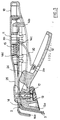
- the gripping device conforms to the invention is intended for a container 1, of the type cooking utensil (saucepan, frying pan, baking dish, ...), generally comprising a bottom and a side wall 3 said skirt having a curved edge 2 which forms a rim pourer.
- This gripping device comprises two members 13 and 14 forming a clamp mounted on a body of grip 11.
- the latter in this example has the form a pan tail with a rear opening 18 which can allow its suspension to a hook.
- the gripping device could also be in the form of handles or removable handles.
- the members 13 and 14 each have one end, 13a and 14a respectively in the figure, which has a shape complementary to the interior or exterior surface of the curved edge and part of the skirt adjacent to the edge 2.
- the end 13a of the member 13 hugs the outer surface of the skirt and the end 14a of the member 14 follows the interior surface of the skirt.
- Displacement means 12 are adapted to move organs 13 and 14 one relative to the other, between an open position, illustrated in Figure 1, and a closed position, illustrated in Figure 2, in which the ends 13a and 14a pinch the skirt 3 of container 1.
- These displacement means comprise a lever 12 pivotally mounted on the gripping body 11, between a spread position and a retracted position at inside the gripping body 11.
- the latter thus includes a housing adapted to receive the lever in the retracted position, corresponding in the closed position of the members 13 and 14 forming a clamp.
- the lever 12 pivots around an axis 17 of the body grip 11.
- Locking means 16 described subsequently are adapted to hold the organs 13 and 14 in the closed position relative to each other.
- One of the members 14 is movable in translation relative to the gripping body 11.
- the ends 13a, 14a also remain parallel to each other when closing the device gripping and substantially parallel to the skirt 3 of the container 1.
- the gripping device of the invention therefore allows to equip a thick container any, included in the maximum stroke of the translation of the movable member 14.
- the other member 13 is fixed relative to the body grip 11 and conforms to the outer surface of the rim 2 of container 1.
- lever 12 actuation device is fixed under the body of grip 11.
- the member 14 is movable in translation relative to the gripping body 11 and a connecting rod 20 extends between the lever 12 and this member 14 and is adapted to move member 14 in translation when the lever 12 is pivoted.
- the movable member 14 has an end 14b on which is supported on the other end 20b of the connecting rod 20.
- a compensation spring 19 is attached at one end to the lever, and at the other of its ends, at the end 20a of the connecting rod 20 inserted in the lever 2.
- the compensation spring 19 thus exerts a force to the opposite of the container 1 on the end 14b of the member 14 via the connecting rod 20 and thus allows to adjust the spacing between the two members 13 and 14 depending on the thickness of the container 1 and the diameter. Any play in the tightening of the rim 2 by organs 13 and 14 is thus eliminated.
- the connecting rod 20 and the spring 19 thus form locking means 16 adapted to keep organs 13 and 14 in position closed relative to each other.
- At least one portion of the member 14 movable in translation and at least a portion of the lever 12 are adjacent one to the other, these portions comprising racks 22, 23 complementary adapted to mesh with each other and to keep the organ 14 stationary.
- This rack system has a function in case the compensating spring 19 is defective and no longer exerts sufficient force to keep members 13 and 14 tight against the edge curved 2.
- An unlocking button 24 is provided on the swivel lever 12.
- the gripping body 11 has a recess 25 arranged so that in the closed position the unlocking button 24 is housed in this recess 25 and thus passes through the gripping body 11.
- this button 24 To unlock the gripping device, the user presses this button 24 with a finger.
- the compensation spring 19 and the connecting rod 20 do not are therefore more aligned in the direction of translation of the movable member 14, a return spring 15, disposed between the gripping body 11 and the end of the movable member 14, being adapted to exert a force contrary to that of the compensation spring 19 on the member 14 so as to separate the two from one another members 13, 14 forming a clamp.
- This removable gripping device is therefore very safe to use, because it cannot no case open when user squeezes body gripping, especially when moving the container even if the release button is accidentally pushed in.
- the operation of the device in accordance with the invention thus obliges the user when he wants remove this device, place the container beforehand stably so that you can release the pressure fingers on the gripping body in order to obtain the spacing of the gripper members 13, 14.
- the assembly constituted by the connecting rod 20 and the compensation spring 19 is replaced by a blade 20 acting as a connecting rod.
- the blade 20 has one end 20a mounted in lever 12 so that it pivots with the latter when opening and closing the device.
- the other end 20b of the blade 20 is no longer resting on the end 14b of the movable member in translation but comes into engagement with this member 14, at through an opening 14c formed in the length of the movable member 14.
- the blade forming the connecting rod 20 extends thus between the lever 12 and the member 14 and is adapted to move the latter in translation when the lever is rotated.
- the distance between the end 14a, coming in press on the edge 2 of the container 1, and this opening 14c, is determined so as to allow pinching by the device of the rim of the smallest containers existing diameter and thickness.
- the blade 20 by design is sufficiently elastic so that it can be slightly compressed when the device is closed and thus adjust the spacing between the two bodies 13 and 14 to compensate for the different diameters and different thicknesses of cookware.
- the blade 20 thus has a curved profile between its two ends mounted respectively on the member mobile 14 and lever 12, the radius of curvature of this profile being slightly decreased when the blade is compressed.
- the blade 20 In the closed position of the device, the blade 20 extends in a direction parallel to the axis of translation of the movable member 14, that is to say perpendicular to the skirt portion 3 of the container 1 receiving the device, and is adapted to exert a force on the end 14a of the movable member 14 and at exert force in the same direction and in the opposite direction on the end 13a of the other member 13.
- the blade forming a connecting rod 20 thus plays the role of the spring of compensation 19 of the previous embodiment.
- the movable member 14 comprises a part 14d forming a bearing surface for a return spring 15 disposed between this bearing surface 14d and a portion integral with the body 11 of the device gripping.
- the gripping device could have a handle in the shape of a handle.
Landscapes
- Engineering & Computer Science (AREA)
- Food Science & Technology (AREA)
- Cookers (AREA)
- Food-Manufacturing Devices (AREA)
- Details Of Rigid Or Semi-Rigid Containers (AREA)
- Table Equipment (AREA)
- Clamps And Clips (AREA)
Description
La présente invention concerne un dispositif de préhension amovible pour récipient, et notamment pour ustensile culinaire.The present invention relates to a device for removable grip for container, and in particular for cooking utensil.
On connaít des poêles ou des casseroles dont la queue ou les anses sont amovibles. Ces ustensiles sont équipés sur leur paroi externe d'un ou plusieurs éléments mâles de fixation, en forme de goujon ou autre, l'équipement possédant à son extrémité une forme femelle pouvant être introduite et retirée facilement de l'élément de fixation.We know of pots or pans whose tail or handles are removable. These utensils are fitted on their outer wall with one or more male fastening elements, in the form of studs or the like, the equipment having at its end a female form can be easily inserted and removed from the fixing element.
Ce type d'équipement nécessite par conséquent de prééquiper les récipients d'un élément de fixation, par soudage ou rivetage par exemple, ce qui complique la fabrication.This type of equipment therefore requires pre-equip the containers with a fixing element, for example welding or riveting for example, which complicates the manufacturing.
De plus cet élément extérieur est gênant pour l'emboítement des différents ustensiles.In addition, this external element is inconvenient for the nesting of different utensils.
On connaít en outre un dispositif de préhension, décrit dans le brevet US 2 808 284 (cf. le préambule de la revendication 1), comprenant deux mâchoires adaptées à pincer le bord d'un récipient.We also know a gripping device, described in US Patent 2,808,284 (cf. the preamble of claim 1), comprising two jaws suitable for pinching the edge of a container.
Cependant, la mâchoire mobile est déplacée en pivotement sur des tiges de guidage, ce qui assure un positionnement peu précis des mâchoires sur la jupe du récipient.However, the movable jaw is moved in pivoting on guide rods, which ensures imprecise positioning of the jaws on the skirt of the container.
En outre, le déplacement en pivotement de l'organe mobile n'est adapté qu'à une seule épaisseur de jupe de récipient, les mâchoires n'étant plus parallèles en position fermée du dispositif de préhension pour d'autres épaisseurs de récipient.In addition, the pivoting movement of the movable member is only suitable for a single thickness of container skirt, jaws no longer parallel in the closed position of the gripping device for other container thicknesses.
La présente invention se propose de résoudre les inconvénients précités grâce à un dispositif de préhension amovible qui ne requiert pas de prééquipement des récipients, qui simplifie en outre la manipulation de ces récipients et est adaptable à des récipients différents en épaisseur. The present invention proposes to solve the disadvantages mentioned above thanks to a device for removable grip which does not require pre-equipment containers, which further simplifies handling of these containers and is adaptable to containers different in thickness.
Le dispositif de préhension visé par l'invention est amovible et est prévu pour un récipient, notamment un ustensile culinaire qui comporte une paroi latérale dite jupe ayant un bord recourbé.The gripping device targeted by the invention is removable and is intended for a container, in particular a cooking utensil which has a side wall said skirt having a curved edge.
Ce dispositif de préhension comprend deux organes formant pince montés sur un corps de préhension et ayant une extrémité de forme complémentaire respectivement à la surface intérieure et extérieure d'une partie de la jupe et du bord recourbé du récipient et des moyens de déplacement adaptés à déplacer ces organes l'un par rapport à l'autre entre une position ouverte et une position fermée dans laquelle les extrémités d'organes pincent la jupe du récipient, lesdits moyens de déplacement comprenant un levier monté en pivotement sur le corps de préhension entre une position écartée et une position escamotée à l'intérieur du corps de préhension.This gripping device comprises two gripper members mounted on a gripping body and having a complementary shaped end respectively on the inner and outer surface part of the skirt and the curved edge of the container and displacement means adapted to move these organs relative to each other between a position open and a closed position in which the organ ends pinch the container skirt, said displacement means comprising a lever mounted pivoting on the gripping body between a spread position and a retracted position inside of the gripping body.
Conformément à l'invention, le dispositif est caractérisé en ce que l'un des organes est mobile en translation par rapport au corps de préhension entre la position ouverte et la position fermée, et en ce qu'une lame formant bielle s'étend entre le levier et ledit organe mobile et est adaptée a déplacer l'organe mobile en translation lorsque le levier est pivoté.According to the invention, the device is characterized in that one of the members is movable in translation relative to the gripping body between the open position and the closed position, and in that a connecting rod blade extends between the lever and said movable member and is adapted to move the movable member in translation when the lever is pivoted.
Ainsi, par simple pincement de la jupe du récipient, on peut saisir le récipient par le dispositif de préhension. Le bord recourbé sert ainsi de butée sur les organes formant pince et tout glissement vertical est empêché. Le dispositif de préhension permet donc de saisir et de déplacer le récipient de manière très fiable.So, by simply pinching the skirt of the container, you can grab the container by the device gripping. The curved edge thus serves as a stop on the gripper members and any vertical sliding is prevented. The gripping device therefore makes it possible to grab and move the container very reliable.
De plus, ce dispositif de préhension ne nécessite pas de fixer des pièces supplémentaires adéquates sur les récipients.In addition, this gripping device does not no need to fix additional parts suitable for containers.
On peut en outre saisir le récipient à n'importe quel endroit du bord du récipient. Il devient ainsi inutile de faire tourner le récipient sur lui-même pour l'orienter suivant un angle prédéterminé avant de le saisir.The container can also be grasped at any which location from the edge of the container. It thus becomes no need to rotate the container on itself to orient it at a predetermined angle before grab.
Ce dispositif de préhension est adaptable à tout récipient à bord verseur, quel que soit son diamètre ou sa forme. En outre, quelle que soit l'épaisseur de la jupe du récipient, on obtient une fixation parfaite du dispositif de préhension, les extrémités des organes formant pince épousant les surfaces extérieures et intérieures de la jupe.This gripping device is adaptable to any container with pouring edge, whatever its diameter or its shape. In addition, regardless of the thickness of the skirt of the container, a perfect fixing of the gripping device, the ends of the organs forming a clip conforming to the exterior surfaces and inside of the skirt.
Le fait de pouvoir retirer la queue ou l'anse du récipient améliore la sécurité lors de l'utilisation de ces récipients, en supprimant les risques d'accrochage, pouvant provoquer le renversement accidentel du récipient, facilite le rangement dans les placards, dans les paniers du lave-vaisselle et donne la possibilité de mettre les articles au four.Being able to remove the tail or handle from the container improves safety when using these containers, by eliminating the risks of snagging, may cause accidental overturning of the container, facilitates storage in cupboards, in the baskets of the dishwasher and gives the possibility of put the items in the oven.
Selon une version préférée de l'invention, ce dispositif comprend des moyens de verrouillage adaptés à maintenir les organes en position fermée l'un par rapport à l'autre.According to a preferred version of the invention, this device comprises locking means adapted to keep the organs in closed position one by compared to each other.
Grâce à ces moyens de verrouillage, le dispositif de préhension peut rester solidaire du récipient tant que l'utilisateur le souhaite.Thanks to these locking means, the gripping device can remain integral with the container as long as the user wishes.
Selon une version avantageuse de l'invention, l'autre organe est fixe par rapport au corps de préhension.According to an advantageous version of the invention, the other organ is fixed relative to the body of gripping.
Cette structure permet de faciliter le positionnement du dispositif de préhension sur le bord recourbé du récipient. En effet, on place l'organe immobile en contact avec la jupe du récipient, puis on actionne les moyens de déplacement pour pincer cette jupe. Le dispositif de préhension est ainsi fixé au récipient de manière précise.This structure facilitates the positioning of the gripping device on the edge curled from the container. Indeed, we place the organ motionless in contact with the container skirt, then actuates the displacement means to pinch this skirt. The gripping device is thus fixed to the container precisely.
D'autres particularités et avantages de l'invention apparaítront encore dans la description ci-après. Other features and advantages of the invention will appear further in the description below.
Aux dessins annexés, donnés à titre d'exemples non limitatifs :
- la figure 1 est une vue en coupe d'un dispositif de préhension en position ouverte conforme à une première réalisation de l'invention ;
- la figure 2 est une vue du dispositif de préhension de la figure 1 en position fermée ; et
- la figure 3 est une vue en coupe d'un dispositif de préhension en position ouverte conforme à une deuxième réalisation de l'invention.
- Figure 1 is a sectional view of a gripping device in the open position according to a first embodiment of the invention;
- Figure 2 is a view of the gripping device of Figure 1 in the closed position; and
- Figure 3 is a sectional view of a gripping device in the open position according to a second embodiment of the invention.
Un premier exemple de réalisation va tout d'abord être décrit en référence aux figures 1 et 2.A first example of realization goes all first be described with reference to Figures 1 and 2.
Le dispositif de préhension conforme à
l'invention est prévu pour un récipient 1, du type
ustensile culinaire (casserole, poêle, plat à four,...),
comportant généralement un fond et une paroi latérale 3
dite jupe ayant un bord recourbé 2 qui forme un rebord
verseur.The gripping device conforms to
the invention is intended for a
Ce dispositif de préhension comprend deux
organes 13 et 14 formant pince montés sur un corps de
préhension 11. Ce dernier a dans cet exemple la forme
d'une queue de casserole avec en partie arrière une
ouverture 18 pouvant permettre sa suspension à un
crochet. Le dispositif de préhension pourrait également
avoir la forme de poignées ou d'anses amovibles.This gripping device comprises two
Les organes 13 et 14 ont chacun une extrémité,
respectivement 13a et 14a sur la figure, qui a une forme
complémentaire de la surface intérieure ou extérieure du
bord recourbé et d'une partie de la jupe adjacente au
bord 2.The
Ici, l'extrémité 13a de l'organe 13 épouse la
surface extérieure de la jupe et l'extrémité 14a de
l'organe 14 épouse la surface intérieure de la jupe.Here, the
Des moyens de déplacement 12 sont adaptés à
déplacer les organes 13 et 14 l'un par rapport à
l'autre, entre une position ouverte, illustrée à la
figure 1, et une position fermée, illustrée à la figure
2, dans laquelle les extrémités 13a et 14a pincent la
jupe 3 du récipient 1.Displacement means 12 are adapted to
move
Ces moyens de déplacement comprennent un levier
12 monté en pivotement sur le corps de préhension 11,
entre une position écartée et une position escamotée à
l'intérieur du corps de préhension 11.These displacement means comprise a
Ce dernier comprend ainsi, un logement adapté à
recevoir le levier en position escamotée, correspondant
à la position fermée des organes 13 et 14 formant pince.The latter thus includes a housing adapted to
receive the lever in the retracted position, corresponding
in the closed position of the
Ainsi, lorsque le dispositif de préhension est
fixé sur le récipient 1, il a sensiblement la forme
extérieure d'une queue classique de casserole.So when the gripping device is
attached to
Le levier 12 pivote autour d'un axe 17 du corps
de préhension 11.The
Des moyens de verrouillage 16, décrits
ultérieurement, sont adaptés à maintenir les organes 13
et 14 en position fermée l'un par rapport à l'autre.Locking means 16, described
subsequently are adapted to hold the
L'un des organes 14 est mobile en translation
par rapport au corps de préhension 11.One of the
Les extrémités 13a, 14a restent aussi parallèles
l'une à l'autre lors de la fermeture du dispositif de
préhension et sensiblement parallèles à la jupe 3 du
récipient 1.The
Le dispositif de préhension de l'invention
permet donc d'équiper un récipient d'épaisseur
quelconque, comprise dans la course maximale de la
translation de l'organe mobile 14.The gripping device of the invention
therefore allows to equip a thick container
any, included in the maximum stroke of the
translation of the
L'autre organe 13 est fixe par rapport au corps
de préhension 11 et épouse la surface extérieure du
rebord 2 du récipient 1.The
Pour faciliter la manipulation par l'utilisateur
et obtenir une meilleure ergonomie, le levier 12
d'actionnement du dispositif est fixé sous le corps de
préhension 11. To facilitate handling by the user
and get better ergonomics, lever 12
actuation device is fixed under the body of
Conformément à l'invention, l'organe 14 est
mobile en translation par rapport au corps de préhension
11 et une bielle 20 s'étend entre le levier 12 et cet
organe 14 et est adaptée à déplacer l'organe 14 en
translation lorsque le levier 12 est pivoté.According to the invention, the
Ainsi, lorsque le levier 12 est pivoté autour de
son axe 17 solidaire du corps de préhension 11,
l'extrémité 20a de la bielle 20 introduite dans le
levier 12 est également pivotée en rotation de sorte
qu'en fin de course du levier, la bielle 20 est alignée
avec l'axe de translation de l'organe 14, c'est-à-dire
l'axe longitudinal du corps de préhension 11.Thus, when the
L'organe mobile 14 a une extrémité 14b sur
laquelle est appuyée l'autre extrémité 20b de la bielle
20.The
Dans cet exemple, un ressort de compensation 19
est fixé à une de ses extrémités au levier, et à l'autre
de ses extrémités, à l'extrémité 20a de la bielle 20
introduite dans le levier 2.In this example, a
En position fermée, illustrée à la figure 2, le
ressort de compensation 19 exerce ainsi une force à
l'opposé du récipient 1 sur l'extrémité 14b de l'organe
14 par l'intermédiaire de la bielle 20 et permet ainsi
d'ajuster l'écartement entre les deux organes 13 et 14
en fonction de l'épaisseur du récipient 1 et du
diamètre. Tout jeu au niveau du serrage du rebord 2 par
les organes 13 et 14 est ainsi éliminé. La bielle 20 et
le ressort 19 forment ainsi des moyens de verrouillage
16 adaptés à maintenir les organes 13 et 14 en position
fermée l'un par rapport à l'autre.In the closed position, illustrated in Figure 2, the
De préférence, en position fermée, au moins une
portion de l'organe 14 mobile en translation et au moins
une portion du levier 12 sont adjacentes l'une à
l'autre, ces portions comportant des crémaillères 22, 23
complémentaires adaptées à s'engrener l'une dans l'autre
et à maintenir immobile l'organe 14. Preferably, in the closed position, at least one
portion of the
Ce système de crémaillère a ainsi une fonction
de sécurité au cas où le ressort de compensation 19 est
défectueux et n'exerce plus une force suffisante pour
maintenir les organes 13 et 14 serrés contre le bord
recourbé 2.This rack system has a function
in case the compensating
Un bouton de déverrouillage 24 est prévu sur le
levier pivotant 12.An unlocking
Le corps de préhension 11 comporte un évidement
25 disposé de telle sorte qu'en position fermée, le
bouton de déverrouillage 24 est logé dans cet évidement
25 et traverse ainsi le corps de préhension 11.The gripping
Pour déverrouiller le dispositif de préhension,
l'utilisateur appuie avec un doigt sur ce bouton 24.To unlock the gripping device,
the user presses this
Le ressort de compensation 19 et la bielle 20 ne
sont donc plus alignés dans la direction de translation
de l'organe mobile 14, un ressort de rappel 15, disposé
entre le corps de préhension 11 et l'extrémité de
l'organe mobile 14, étant adapté à exercer une force
contraire à celle du ressort de compensation 19 sur
l'organe 14 de façon à écarter l'un de l'autre les deux
organes 13, 14 formant pince.The
Il faut donc, lors du déverrouillage du
dispositif à la fois appuyer sur le bouton de
déverrouillage 24 et ne pas serrer le corps de
préhension 11 du dispositif afin de permettre aux
organes 13, 14 de s'écarter l'un de l'autre.It is therefore necessary, when unlocking the
device at once press the button
unlock 24 and do not tighten the body of
gripping 11 of the device in order to allow the
Ce dispositif de préhension amovible est donc d'une grande sécurité d'utilisation, car il ne peut en aucun cas s'ouvrir lorsque l'utilisateur serre le corps de préhension, notamment lors du déplacement du récipient, même si le bouton de déverrouillage est enfoncé accidentellement.This removable gripping device is therefore very safe to use, because it cannot no case open when user squeezes body gripping, especially when moving the container even if the release button is accidentally pushed in.
Le fonctionnement du dispositif conforme à
l'invention oblige ainsi l'utilisateur lorsqu'il veut
retirer ce dispositif, à poser au préalable le récipient
de manière stable, afin de pouvoir relâcher la pression
des doigts sur le corps de préhension en vue d'obtenir
l'écartement des organes formant pince 13, 14.The operation of the device in accordance with
the invention thus obliges the user when he wants
remove this device, place the container beforehand
stably so that you can release the pressure
fingers on the gripping body in order to obtain
the spacing of the
Un deuxième exemple de réalisation est représenté à la figure 3. Les éléments communs à l'exemple précédent et portant les mêmes références ne seront pas redécrits ci-dessus.A second example of embodiment is shown in Figure 3. The elements common to the previous example and bearing the same references does will not be described above.
Dans cette réalisation, l'ensemble constitué par
la bielle 20 et le ressort de compensation 19 est
remplacé par une lame 20 jouant le rôle de bielle. Comme
précédemment, la lame 20 a une extrémité 20a montée dans
le levier 12 de sorte qu'elle pivote avec ce dernier
lors de l'ouverture et la fermeture du dispositif.In this embodiment, the assembly constituted by
the connecting
L'autre extrémité 20b de la lame 20 n'est plus
en appui sur l'extrémité 14b de l'organe mobile en
translation mais vient en prise avec cet organe 14, au
travers d'une ouverture 14c ménagée dans la longueur de
l'organe mobile 14. La lame formant bielle 20 s'étend
ainsi entre le levier 12 et l'organe 14 et est adaptée à
déplacer ce dernier en translation lorsque le levier est
pivoté.The
La distance séparant l'extrémité 14a, venant en
appui sur le bord 2 du récipient 1, et cette ouverture
14c, est déterminée de manière à permettre le pinçage
par le dispositif du rebord des récipients de plus petit
diamètre et épaisseur existants.The distance between the
La lame 20 de par sa conception est suffisamment
élastique pour pouvoir être légèrement comprimée lorsque
le dispositif est fermé et ajuster ainsi l'écartement
entre les deux organes 13 et 14 pour compenser les
différents diamètres et les différentes épaisseurs des
articles culinaires.The
La lame 20 a ainsi un profil courbe entre ses
deux extrémités montées respectivement sur l'organe
mobile 14 et le levier 12, le rayon de courbure de ce
profil étant légèrement diminué lorsque la lame est
comprimée. The
En position fermée du dispositif, la lame 20
s'étend dans une direction parallèle à l'axe de
translation de l'organe mobile 14, c'est-à-dire
perpendiculaire à la portion de jupe 3 du récipient 1
recevant le dispositif, et est adaptée à exercer une
force sur l'extrémité 14a de l'organe mobile 14 et à
exercer une force de même direction et de sens opposé
sur l'extrémité 13a de l'autre organe 13. La lame
formant bielle 20 joue ainsi le rôle du ressort de
compensation 19 de l'exemple précédent de réalisation.In the closed position of the device, the
Comme précédemment, l'organe mobile 14 comprend
une partie 14d formant une surface d'appui pour un
ressort de rappel 15 disposé entre cette surface d'appui
14d et une portion solidaire du corps 11 du dispositif
de préhension.As before, the
Bien entendu, de nombreuses modifications pourraient être apportées à l'exemple ci-dessus, sans sortir du cadre de l'invention.Of course, many modifications could be made to the example above, without depart from the scope of the invention.
Ainsi, le dispositif de préhension pourrait avoir un corps de préhension en forme d'anse.Thus, the gripping device could have a handle in the shape of a handle.
Claims (7)
- A detachable gripper system for a vessel (1), inter alia a cooking utensil, the vessel (1) having a lateral wall (3) or "skirt" having a curved edge (2), the said system comprising two members (13, 14) which form a clamp and which are mounted on a gripper body (11) and which have one end (13a, 14a) of complementary shape respectively to the inner and outer surface of a part of the skirt (3) and of the curved edge (2) of the said vessel and movement means (12, 20) adapted to move the said members (13, 14) relatively to one another between an open position and a closed position in which the said member ends (13a, 14a) clamp the skirt (3) of the vessel (1), the said movement means comprising a lever (12) mounted for pivoting on the gripper body (11) between an extended position and a position retracted inside the gripper body (11) between the said open position and said closed position, characterised in that one of the members (14) is movable in translation relatively to the gripper body (11) and in that a strip forming a link (20) extends between the lever (12) and the said movable member (14) and is adapted to move the movable member (14) in translation when the lever (12) is pivoted.
- A gripper system according to claim 1, characterised in that it comprises locking means (16) adapted to hold the said members (13, 14) in the closed position relative to one another.
- A gripper system according to claim 1 or 2, characterised in that the other member (13) is fixed relatively to the gripper body (11).
- A gripper system according to any one of the claims 1 to 3, characterised in that a compensation spring (19, 20) extends in the closed position in a direction parallel to the axis of translation of the said member and is adapted to exert a force on the end (14a) of the said member movable in translation and to exert a force of the same direction and of opposite sense on the end (13a) of the other member.
- A gripper system according to any one of claims 1 to 4, characterised in that the lever (12) is in the retracted position when the said clamp-forming members (13, 14) are in the closed position, the link-forming strip (20) extending, in the said closed position, in a direction parallel to the axis of translation of the said movable member (14), and being adapted to exert a force on the end (14a) of the said member (14) movable in translation and to exert a force in the same direction and of opposite sense on the end (13a) of the other member (13).
- A gripper system according to any one of claims 1 to 5, characterised in that the lever (12) is fixed beneath the gripper body (11).
- A gripper system according to any one of claims 1 to 6, characterised in that at least a portion of the member (14) movable in translation and a portion of the lever (12) are adjacent one another, in the said closed position, the said portion comprising complementary racks (22, 23) adapted to engage in one another and hold the said member (14) immovable.
Applications Claiming Priority (4)
| Application Number | Priority Date | Filing Date | Title |
|---|---|---|---|
| FR9512154A FR2739771A1 (en) | 1995-10-17 | 1995-10-17 | Cooking container with removable handle |
| FR9512154 | 1995-10-17 | ||
| FR9600947 | 1996-01-26 | ||
| FR9600947A FR2739772B1 (en) | 1995-10-17 | 1996-01-26 | REMOVABLE GRIPPING DEVICE FOR CONTAINER |
Publications (2)
| Publication Number | Publication Date |
|---|---|
| EP0769263A1 EP0769263A1 (en) | 1997-04-23 |
| EP0769263B1 true EP0769263B1 (en) | 1999-01-07 |
Family
ID=26232262
Family Applications (1)
| Application Number | Title | Priority Date | Filing Date |
|---|---|---|---|
| EP96402191A Expired - Lifetime EP0769263B1 (en) | 1995-10-17 | 1996-10-15 | Removable device for gripping a recipient |
Country Status (10)
| Country | Link |
|---|---|
| US (1) | US5704092A (en) |
| EP (1) | EP0769263B1 (en) |
| JP (1) | JP3651631B2 (en) |
| CN (1) | CN1120690C (en) |
| CA (1) | CA2187721C (en) |
| DE (2) | DE69601297T2 (en) |
| ES (1) | ES2104536T3 (en) |
| FR (1) | FR2739772B1 (en) |
| RU (1) | RU2168926C2 (en) |
| TR (1) | TR199600820A2 (en) |
Cited By (2)
| Publication number | Priority date | Publication date | Assignee | Title |
|---|---|---|---|---|
| US8899145B2 (en) | 2011-01-31 | 2014-12-02 | Techtronic Power Tools Technology Limited | Grill inserts and tool for the same |
| EP4331452A1 (en) | 2022-08-24 | 2024-03-06 | Sanmiro S.R.L. | Container gripper |
Families Citing this family (64)
| Publication number | Priority date | Publication date | Assignee | Title |
|---|---|---|---|---|
| FR2768914B1 (en) | 1997-10-01 | 1999-12-17 | Seb Sa | REMOVABLE GRIPPING DEVICE FOR CONTAINER |
| FR2802400B1 (en) | 1999-12-15 | 2002-07-12 | Seb Sa | PRESSURE COOKING APPARATUS WITH REMOVABLE HANDLES |
| US6250493B1 (en) | 2000-01-21 | 2001-06-26 | Kinetic Group, L.L.C. | Detachable handle for vessels |
| KR20020001166A (en) * | 2000-06-26 | 2002-01-09 | 조필휘 | Receptacle tongs |
| US6846304B2 (en) * | 2000-07-07 | 2005-01-25 | Jamie Teasdale | Specimen cup holder |
| US20050187492A1 (en) * | 2000-07-07 | 2005-08-25 | Geibel Dean E. | Specimen cup holder |
| KR100372571B1 (en) * | 2000-07-08 | 2003-02-17 | 주식회사 성창베네피나 | Tongs for holding a cooking container |
| ES2180387B1 (en) * | 2000-08-11 | 2004-06-16 | Sung Chang Mart, Co., Ltd. | TENAZA TO SUBJECT A COOKING CONTAINER. |
| US6318776B1 (en) * | 2000-08-22 | 2001-11-20 | Sung Chang Mart Co., Ltd. | Tongs for holding cooking container |
| FR2813516B1 (en) * | 2000-09-04 | 2002-12-27 | Dja Dodane Jean Et Associes | REMOVABLE DEVICE FOR SEIZING, LIFTING, HANDLING AND POURING COOKING UTENSILS WITH TWO HANDLES |
| US6260733B1 (en) | 2000-09-08 | 2001-07-17 | Regal Ware, Inc. | Releasable handle for cookware |
| FR2818885B1 (en) | 2000-12-29 | 2003-02-21 | Expl Ets Andre Verdier Sa | REMOVABLE HANDLE FOR CONTAINER, NOTAMMNENT CASSEROLE |
| ITVR20010015A1 (en) * | 2001-02-14 | 2002-08-14 | Maria Grazia Fiocco | HOOKING DEVICE FOR REMOVABLE HANDLES APPLICABLE TO POTS, PANS OR SIMILAR AND TOOLS IN GENERAL |
| US6439420B1 (en) * | 2001-03-29 | 2002-08-27 | Jong Peter Park | Detachable handle for cooking utensil |
| KR20030013789A (en) * | 2001-08-09 | 2003-02-15 | 박종도 | A separable handle for cooking vessel |
| US6439421B1 (en) * | 2001-11-29 | 2002-08-27 | George Lin | Detachable device handle mounting structure |
| ITPO20010009A1 (en) * | 2001-12-19 | 2003-06-19 | Pacenti Giulio Cesare | HANDLE FOR COOKING TOOLS PROVIDED WITH TEMPERATURE INDICATOR DEVICE |
| KR100436965B1 (en) * | 2002-04-12 | 2004-06-23 | 남상채 | Handle have the link type clamping device |
| KR20030096845A (en) | 2002-06-18 | 2003-12-31 | 박종도 | A separable handle for pressure pot |
| FR2842718B1 (en) | 2002-07-24 | 2005-02-11 | Seb Sa | REMOVABLE AND ADAPTABLE GRIPPING DEVICE HAVING VARIOUS RECIPIENT THICKERS |
| FR2842717B1 (en) * | 2002-07-24 | 2005-02-11 | Seb Sa | REMOVABLE DEVICE FOR GRIPPING WITHOUT CHANGE OF HANDLING |
| FR2842719B1 (en) | 2002-07-24 | 2005-02-11 | Seb Sa | REMOVABLE DEVICE FOR GRIPPING WITH SAFETY |
| US7165489B1 (en) | 2002-08-26 | 2007-01-23 | Products Of Tomorrow, Inc. | Cooking vessel |
| US6694868B1 (en) * | 2003-05-01 | 2004-02-24 | Ming-Tsun Hung | Detachable pan handle structure |
| US7789015B2 (en) * | 2004-08-31 | 2010-09-07 | Sunbeam Products, Inc. | Handle for electric cooking appliance |
| ATE427060T1 (en) * | 2004-11-23 | 2009-04-15 | Product Works Ltd | DETACHABLE HANDLE |
| GB2421678A (en) * | 2004-12-29 | 2006-07-05 | Microwise Cookware Ltd | Microwave oven spatula with grip member |
| US20060272512A1 (en) * | 2005-06-02 | 2006-12-07 | Chung-Che Wang | Connecting member for the handle of a pan |
| US20070186379A1 (en) * | 2006-01-19 | 2007-08-16 | Mcdonald Kevin | Removable handle for trash vessel hinged access door |
| JP4851812B2 (en) * | 2006-02-28 | 2012-01-11 | 株式会社東芝 | Temperature detection unit and cooking vessel equipped with temperature detection unit |
| FR2898032B1 (en) * | 2006-03-06 | 2008-04-18 | Seb Sa | REMOVABLE GRIPPING DEVICE WITH OPENING MEANS FOR CLAMPING BODIES |
| FR2898031B1 (en) * | 2006-03-06 | 2008-04-18 | Seb Sa | REMOVABLE GRIPPING DEVICE |
| US8336751B2 (en) * | 2006-10-06 | 2012-12-25 | Covidien Lp | Grasping jaw mechanism |
| KR200439045Y1 (en) * | 2007-02-08 | 2008-03-17 | 김종득 | A Detachable Handle for Cooking Vessels |
| DE102008005567B4 (en) * | 2008-01-22 | 2011-12-22 | Heinrich Baumgarten KG Spezialfabrik für Beschlagteile | Fitting part for attachment to a cooking or frying vessel |
| WO2010005158A1 (en) * | 2008-07-11 | 2010-01-14 | Jung Jin Heon | Detachable handle for cooking utensils |
| FR2937237B1 (en) | 2008-10-16 | 2011-03-25 | Tele Shopping | DEVICE FOR REMOVABLE GRIPPING OF A CULINARY CONTAINER AND CULINARY CONTAINER PROVIDED WITH SUCH A DEVICE. |
| US8276507B1 (en) * | 2008-11-11 | 2012-10-02 | National Presto Industries, Inc. | Two-piece handle design for pressure cooker |
| KR101140398B1 (en) * | 2009-02-27 | 2012-07-12 | 조철환 | a pot and pan grip |
| CN101584563B (en) * | 2009-06-12 | 2011-01-26 | 许锡波 | Combined structure of panhandle and pan body |
| KR101063568B1 (en) * | 2009-10-27 | 2011-09-07 | 김명임 | Removable Cookware Handle |
| KR101147113B1 (en) | 2009-11-30 | 2012-05-17 | 주식회사 태일금속 | Detachable handle for cooker |
| FR2954687B1 (en) * | 2009-12-31 | 2012-03-09 | Seb Sa | REMOVABLE HANDLE |
| FR2956021A1 (en) * | 2010-02-11 | 2011-08-12 | Sitram | Removable handle for use in cooking vessel i.e. pot bowl, has handle body carrying blocking units that block arms in tightening configuration, and end forming tabs located at level of fixation end |
| US9277836B2 (en) * | 2010-06-24 | 2016-03-08 | AGD Holdings Limited | Cookware |
| CN101904704B (en) * | 2010-08-02 | 2012-02-29 | 浙江苏泊尔股份有限公司 | Removable handle |
| US8490816B1 (en) * | 2010-08-18 | 2013-07-23 | Juan M. Pacheco | Apparatus for inspecting discarded articles prior to disposal |
| USD671363S1 (en) | 2011-01-31 | 2012-11-27 | Techtronic Power Tools Technology Limited | Portion of a grill |
| USD671364S1 (en) | 2011-01-31 | 2012-11-27 | Techtronic Power Tools Technology Limited | Portion of a grill |
| FR2977786B1 (en) | 2011-07-13 | 2014-11-14 | Seb Sa | REMOVABLE ELECTROMECHANICAL REMOVAL DEVICE |
| FR2977783B1 (en) * | 2011-07-13 | 2014-03-14 | Seb Sa | RECHARGEABLE REMOVABLE HANDLE |
| JP5266425B1 (en) * | 2012-09-07 | 2013-08-21 | 克子 小林 | Putting on and taking off the cooking pan |
| FR3002428B1 (en) * | 2013-02-27 | 2015-02-20 | Seb Sa | DEVICE FOR REMOVABLE GRIPPING OF A CULINARY CONTAINER PROVIDED WITH ANTIRETURN MEANS OF TWO ARMS |
| FR3017040B1 (en) * | 2014-02-06 | 2016-07-22 | Seb Sa | DETECTION DEVICE FOR REMOVING A CULINARY CONTAINER WITH A CLAMPING CLAMP |
| CN104146633B (en) * | 2014-07-16 | 2017-01-11 | 浙江爱仕达电器股份有限公司 | Detachable handle of pot |
| FR3038506B1 (en) * | 2015-07-08 | 2017-07-07 | Seb Sa | REMOVABLE HANDLE WITH OPENING SYSTEM WITH TWO SWIVEL BUTTONS |
| FR3050919A1 (en) * | 2016-05-03 | 2017-11-10 | Cristel | KITCHEN USTENSILE WITH REMOVABLE HANDLE |
| FR3058307B1 (en) | 2016-11-10 | 2019-06-21 | Seb S.A. | FOOD PROCESSING DEVICE COOPERATING WITH MULTIPLE COOKING CONTAINERS |
| US11517153B2 (en) * | 2017-01-03 | 2022-12-06 | Gregory Darren Koke | Removable handle for cooking utensil |
| WO2018171646A1 (en) * | 2017-03-21 | 2018-09-27 | Meyer Intellectual Properties Limited | Cookware article and utensil handle |
| CN208144932U (en) * | 2017-12-28 | 2018-11-27 | 苏州河艺岭进出口有限公司 | A kind of adjusting detachable boiler handle |
| US10888199B2 (en) * | 2019-01-28 | 2021-01-12 | Ok Bin Im | Utility pan handle |
| CN110464229B (en) * | 2019-07-23 | 2020-09-22 | 浙江意可味厨具制造有限公司 | Panhandle easy to adjust and disassemble |
| USD952463S1 (en) * | 2019-12-16 | 2022-05-24 | Mark Oleynik | Container handle |
Family Cites Families (11)
| Publication number | Priority date | Publication date | Assignee | Title |
|---|---|---|---|---|
| US1453543A (en) * | 1921-05-19 | 1923-05-01 | Bonser Fred | Grasping instrument |
| US2137180A (en) * | 1937-11-04 | 1938-11-15 | Attilio V Porro | Pan lifter |
| US2200432A (en) * | 1939-03-28 | 1940-05-14 | Reed Bert | Pan lifter |
| US2262273A (en) * | 1939-08-05 | 1941-11-11 | Ferrara Joseph Agnew | Lifter for cans or the like |
| US2358565A (en) * | 1943-07-22 | 1944-09-19 | Dunlap Samuel David | Tongs |
| US2808284A (en) * | 1955-12-20 | 1957-10-01 | Chris M Rasmussen | Lifters for pots and pans |
| US3059809A (en) * | 1960-09-22 | 1962-10-23 | Iii Alexander C Thompson | Utensil or set of utensils with removable handle |
| FR1326544A (en) * | 1962-03-29 | 1963-05-10 | Laguionie & Cie | Detachable handle for kitchen and household utensils |
| FR1361405A (en) * | 1963-04-03 | 1964-05-22 | Detachable handle for ear container | |
| AU6344473A (en) * | 1972-12-08 | 1975-06-12 | Hoos G & Co Pty Ltd | Detachable handle |
| FR2484820B1 (en) * | 1980-06-23 | 1985-10-04 | Letang & Remy Ets | REMOVABLE HANDLE FOR Grabbing Dishes, Saucepans, and the Like |
-
1996
- 1996-01-26 FR FR9600947A patent/FR2739772B1/en not_active Expired - Lifetime
- 1996-10-11 CA CA002187721A patent/CA2187721C/en not_active Expired - Lifetime
- 1996-10-15 ES ES96402191T patent/ES2104536T3/en not_active Expired - Lifetime
- 1996-10-15 DE DE69601297T patent/DE69601297T2/en not_active Expired - Lifetime
- 1996-10-15 DE DE0769263T patent/DE769263T1/en active Pending
- 1996-10-15 EP EP96402191A patent/EP0769263B1/en not_active Expired - Lifetime
- 1996-10-16 JP JP27315996A patent/JP3651631B2/en not_active Expired - Lifetime
- 1996-10-16 CN CN96112428A patent/CN1120690C/en not_active Expired - Lifetime
- 1996-10-16 RU RU96120770/13A patent/RU2168926C2/en active
- 1996-10-17 TR TR96/00820A patent/TR199600820A2/en unknown
- 1996-10-17 US US08/733,646 patent/US5704092A/en not_active Expired - Lifetime
Cited By (2)
| Publication number | Priority date | Publication date | Assignee | Title |
|---|---|---|---|---|
| US8899145B2 (en) | 2011-01-31 | 2014-12-02 | Techtronic Power Tools Technology Limited | Grill inserts and tool for the same |
| EP4331452A1 (en) | 2022-08-24 | 2024-03-06 | Sanmiro S.R.L. | Container gripper |
Also Published As
| Publication number | Publication date |
|---|---|
| ES2104536T3 (en) | 1999-04-01 |
| CA2187721A1 (en) | 1997-04-18 |
| JP3651631B2 (en) | 2005-05-25 |
| JPH09164085A (en) | 1997-06-24 |
| CN1151855A (en) | 1997-06-18 |
| CA2187721C (en) | 2005-06-21 |
| DE769263T1 (en) | 1998-01-02 |
| RU2168926C2 (en) | 2001-06-20 |
| DE69601297D1 (en) | 1999-02-18 |
| FR2739772A1 (en) | 1997-04-18 |
| EP0769263A1 (en) | 1997-04-23 |
| DE69601297T2 (en) | 1999-08-26 |
| TR199600820A2 (en) | 1997-05-21 |
| CN1120690C (en) | 2003-09-10 |
| ES2104536T1 (en) | 1997-10-16 |
| FR2739772B1 (en) | 1997-12-26 |
| US5704092A (en) | 1998-01-06 |
Similar Documents
| Publication | Publication Date | Title |
|---|---|---|
| EP0769263B1 (en) | Removable device for gripping a recipient | |
| EP0906742B1 (en) | Removable device for gripping a recipient | |
| EP1523265B1 (en) | Removable grip handle device adaptable to containers of different thickness | |
| EP2243408B1 (en) | Removable gripping device for a cooking vessel and cooking vessel provided with such a device | |
| EP3319497B1 (en) | Removable handle | |
| CA2841680C (en) | Removable grasping device for cooking container equipped with non-return means for two arms | |
| EP3345520B1 (en) | Removable handle provided with an opening system with a pivoting button | |
| EP2773250B1 (en) | Removable gripping device for a cooking vessel without indexing | |
| WO2011080482A1 (en) | Removable handle | |
| CA2841678C (en) | Removable grasping device for a cooking container equipped with non-return means for a rotary clamping foot | |
| EP3319498A1 (en) | Removable handle provided with an opening system with two rocker buttons | |
| FR2739771A1 (en) | Cooking container with removable handle | |
| EP0852924B1 (en) | Gripping element for cooking utensil | |
| EP0900633A1 (en) | Ring pushing pliers | |
| FR2956021A1 (en) | Removable handle for use in cooking vessel i.e. pot bowl, has handle body carrying blocking units that block arms in tightening configuration, and end forming tabs located at level of fixation end | |
| FR2535292A1 (en) | Lid opening device for rolling bin comprising such a device | |
| FR2730917A1 (en) | BAKING KIT WITH ANNULAR HANDLE | |
| FR3138996A1 (en) | Container gripping device. | |
| EP4331452A1 (en) | Container gripper | |
| WO2023208896A1 (en) | Removable handle comprising a movable lock provided with an anti-reverse device | |
| EP0824877A1 (en) | Device for carrying a receptacle, especially a basket or a car seat for infants | |
| FR2573643A1 (en) | Container lid having an adjustable steam release |
Legal Events
| Date | Code | Title | Description |
|---|---|---|---|
| PUAI | Public reference made under article 153(3) epc to a published international application that has entered the european phase |
Free format text: ORIGINAL CODE: 0009012 |
|
| AK | Designated contracting states |
Kind code of ref document: A1 Designated state(s): BE DE ES GB IT NL |
|
| ITCL | It: translation for ep claims filed |
Representative=s name: BARZANO'E ZANARDO S.P.A. |
|
| GBC | Gb: translation of claims filed (gb section 78(7)/1977) | ||
| 17P | Request for examination filed |
Effective date: 19970729 |
|
| REG | Reference to a national code |
Ref country code: ES Ref legal event code: BA2A Ref document number: 2104536 Country of ref document: ES Kind code of ref document: T1 |
|
| 17Q | First examination report despatched |
Effective date: 19970912 |
|
| TCNL | Nl: translation of patent claims filed | ||
| DET | De: translation of patent claims | ||
| GRAG | Despatch of communication of intention to grant |
Free format text: ORIGINAL CODE: EPIDOS AGRA |
|
| GRAG | Despatch of communication of intention to grant |
Free format text: ORIGINAL CODE: EPIDOS AGRA |
|
| GRAH | Despatch of communication of intention to grant a patent |
Free format text: ORIGINAL CODE: EPIDOS IGRA |
|
| GRAH | Despatch of communication of intention to grant a patent |
Free format text: ORIGINAL CODE: EPIDOS IGRA |
|
| GRAA | (expected) grant |
Free format text: ORIGINAL CODE: 0009210 |
|
| AK | Designated contracting states |
Kind code of ref document: B1 Designated state(s): BE DE ES GB IT NL |
|
| REF | Corresponds to: |
Ref document number: 69601297 Country of ref document: DE Date of ref document: 19990218 |
|
| ITF | It: translation for a ep patent filed | ||
| GBT | Gb: translation of ep patent filed (gb section 77(6)(a)/1977) |
Effective date: 19990212 |
|
| REG | Reference to a national code |
Ref country code: ES Ref legal event code: FG2A Ref document number: 2104536 Country of ref document: ES Kind code of ref document: T3 |
|
| PLBE | No opposition filed within time limit |
Free format text: ORIGINAL CODE: 0009261 |
|
| STAA | Information on the status of an ep patent application or granted ep patent |
Free format text: STATUS: NO OPPOSITION FILED WITHIN TIME LIMIT |
|
| 26N | No opposition filed | ||
| REG | Reference to a national code |
Ref country code: GB Ref legal event code: IF02 |
|
| PGFP | Annual fee paid to national office [announced via postgrant information from national office to epo] |
Ref country code: GB Payment date: 20151019 Year of fee payment: 20 Ref country code: IT Payment date: 20151014 Year of fee payment: 20 Ref country code: DE Payment date: 20151014 Year of fee payment: 20 |
|
| PGFP | Annual fee paid to national office [announced via postgrant information from national office to epo] |
Ref country code: NL Payment date: 20150921 Year of fee payment: 20 Ref country code: BE Payment date: 20151029 Year of fee payment: 20 Ref country code: ES Payment date: 20151026 Year of fee payment: 20 |
|
| REG | Reference to a national code |
Ref country code: DE Ref legal event code: R071 Ref document number: 69601297 Country of ref document: DE |
|
| REG | Reference to a national code |
Ref country code: NL Ref legal event code: MK Effective date: 20161014 |
|
| REG | Reference to a national code |
Ref country code: GB Ref legal event code: PE20 Expiry date: 20161014 |
|
| REG | Reference to a national code |
Ref country code: ES Ref legal event code: FD2A Effective date: 20170126 |
|
| PG25 | Lapsed in a contracting state [announced via postgrant information from national office to epo] |
Ref country code: GB Free format text: LAPSE BECAUSE OF EXPIRATION OF PROTECTION Effective date: 20161014 |
|
| PG25 | Lapsed in a contracting state [announced via postgrant information from national office to epo] |
Ref country code: ES Free format text: LAPSE BECAUSE OF EXPIRATION OF PROTECTION Effective date: 20161016 |